EP2847404B1 - Ausgleichsscharniervorrichtung mit bremse - Google Patents
Ausgleichsscharniervorrichtung mit bremse Download PDFInfo
- Publication number
- EP2847404B1 EP2847404B1 EP13724772.2A EP13724772A EP2847404B1 EP 2847404 B1 EP2847404 B1 EP 2847404B1 EP 13724772 A EP13724772 A EP 13724772A EP 2847404 B1 EP2847404 B1 EP 2847404B1
- Authority
- EP
- European Patent Office
- Prior art keywords
- pinion
- friction
- connecting means
- contact
- fixed
- Prior art date
- Legal status (The legal status is an assumption and is not a legal conclusion. Google has not performed a legal analysis and makes no representation as to the accuracy of the status listed.)
- Active
Links
Images


Classifications
-
- A—HUMAN NECESSITIES
- A47—FURNITURE; DOMESTIC ARTICLES OR APPLIANCES; COFFEE MILLS; SPICE MILLS; SUCTION CLEANERS IN GENERAL
- A47L—DOMESTIC WASHING OR CLEANING; SUCTION CLEANERS IN GENERAL
- A47L15/00—Washing or rinsing machines for crockery or tableware
- A47L15/42—Details
- A47L15/4251—Details of the casing
- A47L15/4257—Details of the loading door
- A47L15/4261—Connections of the door to the casing, e.g. door hinges
-
- E—FIXED CONSTRUCTIONS
- E05—LOCKS; KEYS; WINDOW OR DOOR FITTINGS; SAFES
- E05D—HINGES OR SUSPENSION DEVICES FOR DOORS, WINDOWS OR WINGS
- E05D11/00—Additional features or accessories of hinges
- E05D11/08—Friction devices between relatively-movable hinge parts
-
- E—FIXED CONSTRUCTIONS
- E05—LOCKS; KEYS; WINDOW OR DOOR FITTINGS; SAFES
- E05F—DEVICES FOR MOVING WINGS INTO OPEN OR CLOSED POSITION; CHECKS FOR WINGS; WING FITTINGS NOT OTHERWISE PROVIDED FOR, CONCERNED WITH THE FUNCTIONING OF THE WING
- E05F1/00—Closers or openers for wings, not otherwise provided for in this subclass
- E05F1/08—Closers or openers for wings, not otherwise provided for in this subclass spring-actuated, e.g. for horizontally sliding wings
- E05F1/10—Closers or openers for wings, not otherwise provided for in this subclass spring-actuated, e.g. for horizontally sliding wings for swinging wings, e.g. counterbalance
- E05F1/12—Mechanisms in the shape of hinges or pivots, operated by springs
- E05F1/1246—Mechanisms in the shape of hinges or pivots, operated by springs with a coil spring perpendicular to the pivot axis
- E05F1/1253—Mechanisms in the shape of hinges or pivots, operated by springs with a coil spring perpendicular to the pivot axis with a compression spring
- E05F1/1261—Mechanisms in the shape of hinges or pivots, operated by springs with a coil spring perpendicular to the pivot axis with a compression spring for counterbalancing
-
- F—MECHANICAL ENGINEERING; LIGHTING; HEATING; WEAPONS; BLASTING
- F24—HEATING; RANGES; VENTILATING
- F24C—DOMESTIC STOVES OR RANGES ; DETAILS OF DOMESTIC STOVES OR RANGES, OF GENERAL APPLICATION
- F24C15/00—Details
- F24C15/02—Doors specially adapted for stoves or ranges
- F24C15/023—Mounting of doors, e.g. hinges, counterbalancing
-
- E—FIXED CONSTRUCTIONS
- E05—LOCKS; KEYS; WINDOW OR DOOR FITTINGS; SAFES
- E05Y—INDEXING SCHEME ASSOCIATED WITH SUBCLASSES E05D AND E05F, RELATING TO CONSTRUCTION ELEMENTS, ELECTRIC CONTROL, POWER SUPPLY, POWER SIGNAL OR TRANSMISSION, USER INTERFACES, MOUNTING OR COUPLING, DETAILS, ACCESSORIES, AUXILIARY OPERATIONS NOT OTHERWISE PROVIDED FOR, APPLICATION THEREOF
- E05Y2201/00—Constructional elements; Accessories therefor
- E05Y2201/20—Brakes; Disengaging means; Holders; Stops; Valves; Accessories therefor
- E05Y2201/252—Type of friction
- E05Y2201/26—Mechanical friction
-
- E—FIXED CONSTRUCTIONS
- E05—LOCKS; KEYS; WINDOW OR DOOR FITTINGS; SAFES
- E05Y—INDEXING SCHEME ASSOCIATED WITH SUBCLASSES E05D AND E05F, RELATING TO CONSTRUCTION ELEMENTS, ELECTRIC CONTROL, POWER SUPPLY, POWER SIGNAL OR TRANSMISSION, USER INTERFACES, MOUNTING OR COUPLING, DETAILS, ACCESSORIES, AUXILIARY OPERATIONS NOT OTHERWISE PROVIDED FOR, APPLICATION THEREOF
- E05Y2201/00—Constructional elements; Accessories therefor
- E05Y2201/20—Brakes; Disengaging means; Holders; Stops; Valves; Accessories therefor
- E05Y2201/262—Type of motion, e.g. braking
- E05Y2201/266—Type of motion, e.g. braking rotary
-
- E—FIXED CONSTRUCTIONS
- E05—LOCKS; KEYS; WINDOW OR DOOR FITTINGS; SAFES
- E05Y—INDEXING SCHEME ASSOCIATED WITH SUBCLASSES E05D AND E05F, RELATING TO CONSTRUCTION ELEMENTS, ELECTRIC CONTROL, POWER SUPPLY, POWER SIGNAL OR TRANSMISSION, USER INTERFACES, MOUNTING OR COUPLING, DETAILS, ACCESSORIES, AUXILIARY OPERATIONS NOT OTHERWISE PROVIDED FOR, APPLICATION THEREOF
- E05Y2201/00—Constructional elements; Accessories therefor
- E05Y2201/60—Suspension or transmission members; Accessories therefor
- E05Y2201/622—Suspension or transmission members elements
- E05Y2201/71—Toothed gearing
- E05Y2201/712—Toothed gearing with incomplete toothing
-
- E—FIXED CONSTRUCTIONS
- E05—LOCKS; KEYS; WINDOW OR DOOR FITTINGS; SAFES
- E05Y—INDEXING SCHEME ASSOCIATED WITH SUBCLASSES E05D AND E05F, RELATING TO CONSTRUCTION ELEMENTS, ELECTRIC CONTROL, POWER SUPPLY, POWER SIGNAL OR TRANSMISSION, USER INTERFACES, MOUNTING OR COUPLING, DETAILS, ACCESSORIES, AUXILIARY OPERATIONS NOT OTHERWISE PROVIDED FOR, APPLICATION THEREOF
- E05Y2201/00—Constructional elements; Accessories therefor
- E05Y2201/60—Suspension or transmission members; Accessories therefor
- E05Y2201/622—Suspension or transmission members elements
- E05Y2201/71—Toothed gearing
- E05Y2201/716—Pinions
-
- E—FIXED CONSTRUCTIONS
- E05—LOCKS; KEYS; WINDOW OR DOOR FITTINGS; SAFES
- E05Y—INDEXING SCHEME ASSOCIATED WITH SUBCLASSES E05D AND E05F, RELATING TO CONSTRUCTION ELEMENTS, ELECTRIC CONTROL, POWER SUPPLY, POWER SIGNAL OR TRANSMISSION, USER INTERFACES, MOUNTING OR COUPLING, DETAILS, ACCESSORIES, AUXILIARY OPERATIONS NOT OTHERWISE PROVIDED FOR, APPLICATION THEREOF
- E05Y2201/00—Constructional elements; Accessories therefor
- E05Y2201/60—Suspension or transmission members; Accessories therefor
- E05Y2201/622—Suspension or transmission members elements
- E05Y2201/71—Toothed gearing
- E05Y2201/722—Racks
-
- E—FIXED CONSTRUCTIONS
- E05—LOCKS; KEYS; WINDOW OR DOOR FITTINGS; SAFES
- E05Y—INDEXING SCHEME ASSOCIATED WITH SUBCLASSES E05D AND E05F, RELATING TO CONSTRUCTION ELEMENTS, ELECTRIC CONTROL, POWER SUPPLY, POWER SIGNAL OR TRANSMISSION, USER INTERFACES, MOUNTING OR COUPLING, DETAILS, ACCESSORIES, AUXILIARY OPERATIONS NOT OTHERWISE PROVIDED FOR, APPLICATION THEREOF
- E05Y2900/00—Application of doors, windows, wings or fittings thereof
- E05Y2900/30—Application of doors, windows, wings or fittings thereof for domestic appliances
- E05Y2900/304—Application of doors, windows, wings or fittings thereof for domestic appliances for dishwashers
-
- E—FIXED CONSTRUCTIONS
- E05—LOCKS; KEYS; WINDOW OR DOOR FITTINGS; SAFES
- E05Y—INDEXING SCHEME ASSOCIATED WITH SUBCLASSES E05D AND E05F, RELATING TO CONSTRUCTION ELEMENTS, ELECTRIC CONTROL, POWER SUPPLY, POWER SIGNAL OR TRANSMISSION, USER INTERFACES, MOUNTING OR COUPLING, DETAILS, ACCESSORIES, AUXILIARY OPERATIONS NOT OTHERWISE PROVIDED FOR, APPLICATION THEREOF
- E05Y2900/00—Application of doors, windows, wings or fittings thereof
- E05Y2900/30—Application of doors, windows, wings or fittings thereof for domestic appliances
- E05Y2900/308—Application of doors, windows, wings or fittings thereof for domestic appliances for ovens
Definitions
- the present invention relates to the field of hinges and refers to a balanced hinge device with brake particularly suitable for appliances such as dishwashers and in general for doors and shutters having horizontal rotation axis for craft and industrial equipment, electrical apparatus, furniture and furnishings.
- Another disadvantage consists in that these known hinges generally do not allow a final closure free stroke having sufficient force to achieve the closing lock of the door by the respective lock.
- An object of the present invention is to propose a balanced hinge device with a brake suitable to exert a braking action in one or more predetermined sectors of the rotation arc of the hinge and to reduce or eliminate the braking action in the other sectors.
- Another object is to provide a compact device reliable and long lasting that it is feasible to easily obtain braked rotation sectors and not depending on the needs and desired functions.
- a further object is to provide a balanced hinge device with brake suitable to balance the door weight and that it is light, cheap, small and reliable.
- Another object is to provide a device suitable to keep the door locked in one or more ranges of angular positions of the same.
- a further object is to provide a device able to keep the door elastically locked in one or more angular positions.
- Another object is to provide a device allowing the door to have a free final closure stroke with a force sufficient to cause the door lock closing.
- a further object is to provide a device whose actuation and friction characteristics can be easily modified and/or set-up during the production stage by substituting one or two parts.
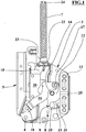
- numeral 1 indicates the balanced hinge device with brake, object of the present invention and comprising a first connecting means 3, preferably made of cut and moulded metal sheet and being mainly flat shaped, assigned to be fixed to a structure or frame such as a dishwasher or another type of apparatus.
- a first connecting means 3 preferably made of cut and moulded metal sheet and being mainly flat shaped, assigned to be fixed to a structure or frame such as a dishwasher or another type of apparatus.
- One end of the first connecting means 3 which in the device operating condition is placed inferiorly in relation to the latter, is pivotally connected via a second pin 4 of the hinge to a second connecting means 5, also preferably made of cut and moulded metal sheet and being mostly flat shaped, assigned to be fixed to a door or shutter of the dishwasher or other apparatus.
- Such connecting means 3, 5 are also mechanically connected to compensating elastic means 7 by kinematic means 8 transmitting to said connecting means 3, 5 a mutual approaching elastic force.
- the elastic means 7 are connected to the first connecting means 3, in particular they are protruding and they are arranged at one end of the first connecting means 3 opposite to the second pin 4, and therefore in the operating condition protrude upward.
- This elastic force produced by the elastic means 7, in the operating condition is assigned to balance the gravitational force acting on the door, opposing to the latter.
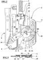
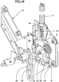
- Such kinematic means 8 comprise a rack means 10 constrained to slide itself parallel by sliding means 20 and a pinion means 12 axially constrained to rotate about a respective first rotation pin 14 fixed to the first connecting means 3.
- the rack means 10 and the pinion means 12 bear corresponding toothed sectors respectively rectilinear and disposed along a circumference arc, mutually engaging transforming the reciprocating circular motion of the pinion means 12 in reciprocating linear motion of the rack means 10.
- Said sliding means 20 comprise at least one guide having a "U" shaped concave section, alternatively, comprise an elongated slot formed through the thickness in the rack means 10 and having elongated sides parallel to the longitudinal axis of the rack means 10 itself and also include a slider, for example in anti-friction plastic material shaped as a soap bar, fixed to the first connecting means 3, in both cases, the rack means 10 can slide itself parallel without jamming.
- the rack means 10 is resiliently pressed by the elastic means 7 which transmits the elastic force to the pinion means 12.
- the kinematic means 8 comprise also an arm means 16 whose ends are connected through respective third 17 and fourth 18 connecting pins respectively to the pinion means 12 and the second connecting means 5.
- the first rotation pin 14 of the pinion means 12 is fixed to the first connecting means 3.
- the first 3 and second 5 connecting means, the rack means 10, the pinion means 12 and the arm means 16 lie approximately on respective parallel geometric planes.
- the geometric axes of the first 14, second 4, third 17 and fourth 18 pins are perpendicular to said geometric plans.
- the distance between the geometric axes of first 14 and third 17 pins is approximately equal to or greater than the engaging radius of the pinion means 12 teeth.
- the toothed sector of the pinion means 12 subtends an angle between about 90° and about 180°; the linear development of this toothed sector of the pinion means 12 has a length approximately equal to the length of the corresponding toothed sector of the rack means 10.
- the distance between the axes of the second 4 and fourth 18 pins is between half and twice, preferably approximately equal, the distance between the axes of the first 14 and third 17 pins.
- said pins 4, 14, 17, 18 are placed at the vertices of a deformable parallelogram geometric quadrilateral.
- the rack means 10 is elastically pressed by the elastic means 7 via a rod means 22.
- the elastic means 7 are a helical spring and whose ends are compressed between a contact 23 of the first connecting means 3, for example cup shaped, and a contact 24 of the rod means 22 having a thin elongated portion connecting the respective contacts 24, consisting of an enlarged head, to its connection to the rack means 10 through the axial slot of said helical spring.
- the arm means 16 is provided with a first contact means 34, for example consisting of a its side shoulder, in the full open condition, assigned to contact a second contact means 35, consisting for example in a projecting and folded side flap of the first connecting means 3.
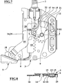
- the device 1 comprises a friction means 9 fixed to the pinion means 12 of the kinematic means 8 that sliding contacts, with mutual sliding, the first connecting means 3 and a contact means 11.
- the pinion means 12 has a through hollow seat 19 to accommodate, at least partially, the friction means 9 so that the seat 19 wall contacts the perimeter faces of the friction means 9.
- the seat 19 consists of a shaped slot formed through the pinion means 12 and the friction means 9 consists of a body approximately plane and shaped in a complementary way to the respective seat 19.
- the contact means 11 is approximately shaped as a bridge with ends fixed to the first connecting means 3 with which defines a partial housing for the pinion means 12 and for the friction means 9.
- the first side portion 13 of the friction means 9 and the corresponding surface of the first connecting means 3 are nearly flat while the second portion 15 of the friction means 9 and the face of the contact means 11 facing the pinion means 12 have respective jutting parts 21, 25 assigned for mutual contact by sliding friction in correspondence of the predetermined rotation arc at which it is necessary that the friction is increased with an intensity depending mainly on the geometric shape and the friction means 9 and the contact means 11 types.
- the jutting part 21 of the friction means 9 is nearly flat and it is joined to the other corresponding second portion 15 of the friction means 9 by means of bevelled end terminations.
- the jutting part 25 of the contact means 11 is facing towards the friction means 9 and consists, for example, in a moulded transverse rib of the contact means 11 itself.
- the seat 19 has an angular extension, with respect to the rotation centre of the pinion means 12, such as the surface of the seat 19 sweeps the entire surface of the face of the contact means 11 that is facing towards the pinion means 12 during the device complete rotation.
- the friction means 9 is made of plastic, nylon, Teflon, or similar also reinforced with fibres.
- the invention provides that most of the elements of the device are made of cut and moulded sheet metal.
- the thickness of the rack means 10 and the pinion means 12 can be greater than that of the other elements to ensure a good engagement and wear resistance.
- these latter can be equipped with optional bushings.
- the operation of the device starting from a maximum opening condition in which the first 3 and second 5 connecting means are at the maximum mutual angular distance and the elastic means 7 are at maximum compression, provides that the elastic force of these elastic means 7 transmitted by the kinematic means 8 to the second connecting means and to the door, balances the weight of the latter allowing easy manual lifting.
- the friction between the contact means 11 and the friction 9 depends on the opening angle and their angular trends can be predetermined properly configuring the second portion 15 of the friction means 9 and in particular the jutting parts 21, 25.
- a simple variant of the invention provides that the friction means 9 is fixed to the rack means 10 instead of the pinion means 12 and the contact means 11 is overlapped on the rack means 10, or obtained in a side of the sliding means 20.
- An advantage of the present invention is to provide a balanced hinge device with a brake suitable to exert a braking action in one or more preset sectors of the rotation arc of the hinge and to reduce or eliminate the braking action in the other sectors.
- Another advantage is to provide a balanced hinge device with brake suitable to balance the door weight and that it is light, cheap, small and reliable.
Landscapes
- Engineering & Computer Science (AREA)
- Mechanical Engineering (AREA)
- Chemical & Material Sciences (AREA)
- Combustion & Propulsion (AREA)
- General Engineering & Computer Science (AREA)
- Pivots And Pivotal Connections (AREA)
Claims (10)
- Ausgleichsscharniervorrichtung mit Bremse umfassend
ein erstes Verbindungsmittel (3), das zugeordnet ist, um an einer Struktur oder einem Rahmen befestigt zu werden, und das mindestens durch kinematische Mittel (8) mit einem zweiten Verbindungsmittel (5) verbunden ist, das zugeordnet ist, um an einer Tür oder einer Klappe befestigt zu werden, und das mindestens ein Reibungsmittel (9) umfasst, wobei
die Vorrichtung (1) ebenso ein elastisches Mittel (7) umfasst, das das mit dem kinematischen Mittel (8) verbundene Tür- oder Klappengewicht ausgleicht, um eine durch das erste elastische Mittel (7) erzeugte wechselseitig ankommende elastische Kraft auf die Verbindungsmittel (3, 5) zu übertragen, wobei
das mindestens eine Reibungsmittel (9) an einem Element des kinematischen Mittels (8) befestigt ist und ein erster Seitenbereich (13) des Reibungsmittels (9) gleitet auf mindestens einem von den Verbindungsmitteln (3, 5) oder einem Element, das an einem davon befestigt ist, wobei
ein zweiter Seitenbereich (15) des Reibungsmittels (9), mindestens in Verbindung mit mindestens einem vorbestimmten Drehbogen der Vorrichtung (1), auf ein mindestens einem Kontaktmittel (11) gleitet, während
das kinematische Mittel (8) weiterhin einen zweiten Scharnierstift (4) für die wechselseitig umlaufende Verbindung des ersten (3) und zweiten Verbindungsmittels (5) umfasst, und
die Vorrichtung (1) ist dadurch gekennzeichnet, dass das kinematische Mittel (8) ein Gestellmittel (10) umfasst, das elastisch durch das erste elastische Mittel (7) betätigt wird, und dass sie weiterhin ein Ritzelmittel (12) umfasst, das gezwungen ist, sich axial um einen mit dem ersten Verbindungsmittel (3) verbundenen entsprechenden ersten Stift (14) zu drehen, wobei
das Gestell- (10) und das Ritzelmittel (12) wechselweise in Eingriff stehen und das Ritzelmittel (12) mindestens jeweils einen Sitz (19) für ein entsprechendes des mindestens einen Reibungsmittels (9) aufweist, dessen erster Seitenbereich (13) das erste Verbindungsmittel (3) oder ein daran befestigtes Element berührt und dessen zweiter Seitenbereich (15) gegenüber dem ersten (13) in Verbindung mit dem mindestens einen vorbestimmten Bogen auf dem Kontaktmittel (11) gleitet, das an dem ersten Verbindungsmittel (3) befestigt ist, wobei
jeder Sitz (19) ein geformter Schlitz ist, der im Ritzelmittel (12) besteht, und jedes der Reibungsmittel (9) ist ein Körper, der ungefähr flach ist und in einer komplementären Weise bezogen auf den entsprechenden Sitz (19) geformt ist, während
die Vorrichtung weiterhin ein Armmittel (16) umfasst, dessen Enden mittels entsprechenden dritten (17) und vierten Verbindungsstiften (18) entsprechend mit dem Ritzelmittel (12) und dem zweiten Verbindungsmittel (5) verbunden sind. - Vorrichtung gemäß Anspruch 1, dadurch gekennzeichnet, dass der erste Seitenbereich (13) des Reibungsmittels (9) und die entsprechende Oberfläche des ersten Verbindungsmittels (3) nahezu flach sind, wobei
das Kontaktmittel (11) ungefähr brückenförmig ist, wobei die Brücke Enden aufweist, die am ersten Verbindungsmittel (3) befestigt sind, mit dem ein teilweises Gehäuse für das Ritzelmittel (12) und für jedes Reibungsmittel (9) definiert wird, und
der zweite Seitenbereich (15) des Reibungsmittels (9) und/oder die Fläche des Kontaktmittels (11) in Richtung des Ritzelmittels (12) weisen entsprechende vorspringende Teile (21, 25) auf, die zugeordnet sind zum wechselseitigen Kontakt durch Gleitreibung in Verbindung mit dem vorbestimmten Drehbogen. - Vorrichtung gemäß einem der Ansprüche 1 oder 2, dadurch gekennzeichnet, dass der vorspringende Teil (21) nahezu flach ist und mit dem verbleibenden zweiten entsprechenden Bereich (15) des Reibungsmittels (9) mittels abgeschrägter Enden verbunden ist, und dass das vorstehende Teil (25) des Kontaktmittels (11) dem Reibungsmittel (9) zugewandt ist.
- Vorrichtung gemäß einem der vorhergehenden Ansprüche, dadurch gekennzeichnet, dass der Sitz (19) eine winklige Ausdehnung aufweist bezogen auf das Drehzentrum des Ritzelmittels (12), so dass die Oberfläche des Sitzes (19) über die gesamte Oberfläche des Kontaktmittels (11) streicht, die während der vollständigen Drehung der Vorrichtung in Richtung des Ritzelmittels (12) gewandt ist.
- Vorrichtung gemäß einem der vorhergehenden Ansprüche, dadurch gekennzeichnet, dass das Reibungsmittel (9) hergestellt ist aus einem Kunststoffmaterial, Nylon, Teflon oder Ähnlichem, ebenso faserverstärkt.
- Vorrichtung gemäß einem der vorhergehenden Ansprüche, dadurch gekennzeichnet, dass der erste Drehstift (14) des Ritzelmittels (12) am ersten Verbindungsmittel (3) befestigt ist, das auf einer Ebene parallel zur Liegeebene des zweiten Verbindungsmittels (5), des Gestellmittels (10), des Ritzelmittels (12) und des Armmittels (16) liegt.
- Vorrichtung gemäß Anspruch 6, dadurch gekennzeichnet, dass der erste (14), der zweite (4), der dritte (17) und der vierte Stift (18) zu den Liegeebenen rechtwinklig sind, wobei
der Abstand zwischen den Achsen des ersten (14) und dritten Stifts (17) gleich oder größer ist als der Eingriffsradius der Zähne des Ritzelmittels (12), wobei solche Zähne auf einem Segment des Ritzelmittels (12) verteilt sind, das einen Winkel im Bereich zwischen ungefähr 90° und ungefähr 180° begrenzt. - Vorrichtung gemäß Anspruch 7, dadurch gekennzeichnet, dass der Abstand zwischen den Achsen des zweiten (4) und des vierten Stifts (18) zwischen der Hälfte und dem Doppelten, vorzugsweise ungefähr das Gleiche, des Abstands zwischen den Achsen des ersten (14) und des dritten Stifts (17) ist,
wobei die Stifte (14, 4, 17, 18) zu den Scheitelpunkten eines Vierecks angeordnet sind, vorzugsweise eines Parallelogramms. - Vorrichtung gemäß Anspruch 8, dadurch gekennzeichnet, dass das Gestellmittel (10) durch Gleitmittel (20) gezwungen ist, entlang seiner Längsachse zu gleiten, wobei
die Gleitmittel (20) mindestens eine konkave Führung mit U-förmigem Querschnitt umfassen. - Vorrichtung gemäß Anspruch 9, dadurch gekennzeichnet, dass das Gestellmittel (10) elastisch betätigt wird durch das erste elastische Mittel (7) mittels eines Spannstangenmittels (22), wobei
das erste elastische Mittel (7) komprimierte spiralförmige Federarten mit eingreifbaren Enden in Kontakten (23, 24) entsprechend dem ersten Verbindungsmittel (3) und dem Spannstangenmittel (22) umfasst.
Applications Claiming Priority (2)
| Application Number | Priority Date | Filing Date | Title |
|---|---|---|---|
| IT000257A ITBO20120257A1 (it) | 2012-05-09 | 2012-05-09 | Dispositivo a cerniera compensata con freno selettivo |
| PCT/EP2013/059680 WO2013167708A1 (en) | 2012-05-09 | 2013-05-08 | Balanced hinge device with brake |
Publications (3)
| Publication Number | Publication Date |
|---|---|
| EP2847404A1 EP2847404A1 (de) | 2015-03-18 |
| EP2847404B1 true EP2847404B1 (de) | 2016-07-13 |
| EP2847404B8 EP2847404B8 (de) | 2016-10-12 |
Family
ID=46397373
Family Applications (1)
| Application Number | Title | Priority Date | Filing Date |
|---|---|---|---|
| EP13724772.2A Active EP2847404B8 (de) | 2012-05-09 | 2013-05-08 | Ausgleichsscharniervorrichtung mit bremse |
Country Status (5)
| Country | Link |
|---|---|
| US (1) | US9364132B2 (de) |
| EP (1) | EP2847404B8 (de) |
| IT (1) | ITBO20120257A1 (de) |
| PL (1) | PL2847404T3 (de) |
| WO (1) | WO2013167708A1 (de) |
Cited By (1)
| Publication number | Priority date | Publication date | Assignee | Title |
|---|---|---|---|---|
| TWI717210B (zh) * | 2020-02-07 | 2021-01-21 | 無界創新股份有限公司 | 軸向折合結構 |
Families Citing this family (7)
| Publication number | Priority date | Publication date | Assignee | Title |
|---|---|---|---|---|
| EP3444420B1 (de) * | 2016-05-13 | 2020-03-11 | Unind (Shenzhen) Co., Limited | Stilles federscharnier |
| EP3444421B8 (de) * | 2016-05-13 | 2020-07-22 | Unind (Shenzhen) Co., Limited | Federscharnier mit zahnradstruktur |
| IT201600088717A1 (it) * | 2016-08-31 | 2018-03-03 | C M I Cerniere Mecc Industriali Srl | Dispositivo a cerniera con smorzamento del tratto terminale della corsa di chiusura |
| IT201600108628A1 (it) * | 2016-10-27 | 2018-04-27 | C M I Cerniere Mecc Industriali Srl | Dispositivo a cerniera modulare |
| IT201700028318A1 (it) * | 2017-03-14 | 2018-09-14 | C M I Cerniere Mecc Industriali Srl | Dispositivo a cerniera motorizzata |
| AT524337B1 (de) * | 2020-10-22 | 2023-07-15 | Blum Gmbh Julius | Möbelantrieb |
| CN115234113A (zh) * | 2022-09-15 | 2022-10-25 | 江苏玖星精密科技集团有限公司 | 一种具有行程调节功能的门窗开关机构 |
Family Cites Families (19)
| Publication number | Priority date | Publication date | Assignee | Title |
|---|---|---|---|---|
| US2668320A (en) * | 1947-12-16 | 1954-02-09 | Atwood Vacuum Machine Co | Hinged lid and hood support for motor vehicles |
| BE493951A (de) * | 1949-02-23 | 1900-01-01 | ||
| US2721547A (en) * | 1952-05-05 | 1955-10-25 | Tappan Stove Co | Closure mechanism for a cooking range oven |
| US3450125A (en) * | 1966-05-24 | 1969-06-17 | Kelvinator Inc | Counterbalanced hinge for oven doors |
| US3466105A (en) * | 1967-12-21 | 1969-09-09 | Gen Electric | Door-operated rack extending and retracting means for a front-opening appliance cabinet |
| US3820866A (en) * | 1971-07-15 | 1974-06-28 | Maytag Co | Appliance door control mechanism |
| US4021968A (en) * | 1976-05-14 | 1977-05-10 | Kendall Willard E | Counterbalancing hinge for range oven doors or the like |
| US5025776A (en) * | 1990-05-18 | 1991-06-25 | The Stanley Works | Door mounted hinge for oven doors and the like |
| EP1287222B1 (de) * | 2001-02-15 | 2004-04-28 | Gronbach Forschung- und Entwicklungs GmbH & Co. KG | Scharnier für eine herdklappe |
| US6789293B2 (en) * | 2001-09-27 | 2004-09-14 | Mansfield Assemblies Co. | Dampened hinge system for appliance door |
| ITBO20010620A1 (it) * | 2001-10-10 | 2003-04-10 | Cmi Srl | Dispositivo a cerniera controbilanciato frenato per un portello |
| US6986187B2 (en) * | 2002-05-20 | 2006-01-17 | Mansfield Assemblies Co. | Hinge assembly with glide member |
| US6968597B2 (en) * | 2002-05-31 | 2005-11-29 | Mansfield Assemblies Co. | Hinge assembly having improved stop |
| US7017232B1 (en) * | 2005-05-06 | 2006-03-28 | Priddy Thomas G | Load limiting hinge |
| US8201304B2 (en) * | 2009-02-25 | 2012-06-19 | General Electric Company | Compliant door hinge |
| US8250707B2 (en) * | 2009-03-10 | 2012-08-28 | Electrolux Home Products, Inc. | Door hinge assembly with intermediate stop position |
| US8925542B2 (en) * | 2009-07-21 | 2015-01-06 | Mansfield Assemblies Co. | Slow open and/or slow close hinge assembly and hinge system |
| US9404299B2 (en) * | 2012-05-02 | 2016-08-02 | Bsh Home Appliances Corporation | Home appliance with adjustable hinges |
| ITBO20120273A1 (it) * | 2012-05-17 | 2013-11-18 | Cmi Srl | Dispositivo a cerniera bilanciata con freno programmabile |
-
2012
- 2012-05-09 IT IT000257A patent/ITBO20120257A1/it unknown
-
2013
- 2013-05-08 EP EP13724772.2A patent/EP2847404B8/de active Active
- 2013-05-08 US US14/399,578 patent/US9364132B2/en active Active
- 2013-05-08 PL PL13724772T patent/PL2847404T3/pl unknown
- 2013-05-08 WO PCT/EP2013/059680 patent/WO2013167708A1/en not_active Ceased
Cited By (1)
| Publication number | Priority date | Publication date | Assignee | Title |
|---|---|---|---|---|
| TWI717210B (zh) * | 2020-02-07 | 2021-01-21 | 無界創新股份有限公司 | 軸向折合結構 |
Also Published As
| Publication number | Publication date |
|---|---|
| PL2847404T3 (pl) | 2017-01-31 |
| EP2847404B8 (de) | 2016-10-12 |
| EP2847404A1 (de) | 2015-03-18 |
| WO2013167708A1 (en) | 2013-11-14 |
| ITBO20120257A1 (it) | 2013-11-10 |
| US9364132B2 (en) | 2016-06-14 |
| US20150107053A1 (en) | 2015-04-23 |
Similar Documents
| Publication | Publication Date | Title |
|---|---|---|
| EP2847404B1 (de) | Ausgleichsscharniervorrichtung mit bremse | |
| AU2016304607B2 (en) | Hinge device with long reciprocating stroke of a front panel | |
| EP3014039B1 (de) | Scharniervorrichtung mit einer translationsbeschichtungsplatte | |
| EP3519656B1 (de) | Betätigungsvorrichtung für ein hebesystem und hebesystem für türblätter von möbeln | |
| EP3575532B1 (de) | Hebesystem für flügel von möbeln | |
| US7275284B2 (en) | Damping device | |
| CN107002442B (zh) | 家具铰链 | |
| US4744125A (en) | Door closer transmission including an eccentric pinion | |
| EP2850267B1 (de) | Ausgleichsscharniervorrichtung mit rogrammierbarer bremse | |
| US20080209674A1 (en) | Damper arrangement | |
| EP2243914B1 (de) | Scharnier für Flügel oder Türen | |
| US9879462B2 (en) | Hinge assemblies | |
| EP2374974A1 (de) | Scharnier für Türen oder Flügel | |
| EP3788223A1 (de) | Scharniervorrichtung für kühlschränke und einrichtungsgegenstände | |
| EP1302150B1 (de) | Scharnier mit Vorrichtung zum Ausbalancieren und Bremsen einer Tür | |
| EP1764557A2 (de) | Kompaktes Türscharnier | |
| KR102861857B1 (ko) | 전기 모터 구동식 가구 드라이브 | |
| EP1523929B1 (de) | Gewichtsausgleichseinrichtung für eine Tür von einem Haushaltsgerät | |
| CN109267871A (zh) | 一种弹力可调节的家具翻转结构 | |
| ITMI20082001A1 (it) | Dispositivo per la movimentazione verticale di ante per mobili. | |
| CN105064830B (zh) | 家具折叠门的铰链弹性结构 | |
| EP3625419B1 (de) | Multifunktionsscharniervorrichtung | |
| IT202000002605A1 (it) | Dispositivo a cerniera con chiusura smorzata | |
| IT201900018470A1 (it) | Cerniera per anta | |
| ITBO20110049U1 (it) | Dispositivo a cerniera compensata |
Legal Events
| Date | Code | Title | Description |
|---|---|---|---|
| PUAI | Public reference made under article 153(3) epc to a published international application that has entered the european phase |
Free format text: ORIGINAL CODE: 0009012 |
|
| 17P | Request for examination filed |
Effective date: 20141209 |
|
| AK | Designated contracting states |
Kind code of ref document: A1 Designated state(s): AL AT BE BG CH CY CZ DE DK EE ES FI FR GB GR HR HU IE IS IT LI LT LU LV MC MK MT NL NO PL PT RO RS SE SI SK SM TR |
|
| AX | Request for extension of the european patent |
Extension state: BA ME |
|
| DAX | Request for extension of the european patent (deleted) | ||
| GRAP | Despatch of communication of intention to grant a patent |
Free format text: ORIGINAL CODE: EPIDOSNIGR1 |
|
| INTG | Intention to grant announced |
Effective date: 20160128 |
|
| GRAS | Grant fee paid |
Free format text: ORIGINAL CODE: EPIDOSNIGR3 |
|
| GRAA | (expected) grant |
Free format text: ORIGINAL CODE: 0009210 |
|
| AK | Designated contracting states |
Kind code of ref document: B1 Designated state(s): AL AT BE BG CH CY CZ DE DK EE ES FI FR GB GR HR HU IE IS IT LI LT LU LV MC MK MT NL NO PL PT RO RS SE SI SK SM TR |
|
| REG | Reference to a national code |
Ref country code: GB Ref legal event code: FG4D |
|
| RIN1 | Information on inventor provided before grant (corrected) |
Inventor name: GHERARDI, EROS |
|
| REG | Reference to a national code |
Ref country code: AT Ref legal event code: REF Ref document number: 812487 Country of ref document: AT Kind code of ref document: T Effective date: 20160715 Ref country code: CH Ref legal event code: EP |
|
| RAP2 | Party data changed (patent owner data changed or rights of a patent transferred) |
Owner name: C.M.I. CERNIERE MECCANICHE INDUSTRIALI S.R.L. |
|
| REG | Reference to a national code |
Ref country code: IE Ref legal event code: FG4D |
|
| REG | Reference to a national code |
Ref country code: DE Ref legal event code: R096 Ref document number: 602013009368 Country of ref document: DE |
|
| REG | Reference to a national code |
Ref country code: LT Ref legal event code: MG4D |
|
| REG | Reference to a national code |
Ref country code: NL Ref legal event code: MP Effective date: 20160713 |
|
| REG | Reference to a national code |
Ref country code: AT Ref legal event code: MK05 Ref document number: 812487 Country of ref document: AT Kind code of ref document: T Effective date: 20160713 |
|
| PG25 | Lapsed in a contracting state [announced via postgrant information from national office to epo] |
Ref country code: IS Free format text: LAPSE BECAUSE OF FAILURE TO SUBMIT A TRANSLATION OF THE DESCRIPTION OR TO PAY THE FEE WITHIN THE PRESCRIBED TIME-LIMIT Effective date: 20161113 Ref country code: FI Free format text: LAPSE BECAUSE OF FAILURE TO SUBMIT A TRANSLATION OF THE DESCRIPTION OR TO PAY THE FEE WITHIN THE PRESCRIBED TIME-LIMIT Effective date: 20160713 Ref country code: LT Free format text: LAPSE BECAUSE OF FAILURE TO SUBMIT A TRANSLATION OF THE DESCRIPTION OR TO PAY THE FEE WITHIN THE PRESCRIBED TIME-LIMIT Effective date: 20160713 Ref country code: NO Free format text: LAPSE BECAUSE OF FAILURE TO SUBMIT A TRANSLATION OF THE DESCRIPTION OR TO PAY THE FEE WITHIN THE PRESCRIBED TIME-LIMIT Effective date: 20161013 Ref country code: HR Free format text: LAPSE BECAUSE OF FAILURE TO SUBMIT A TRANSLATION OF THE DESCRIPTION OR TO PAY THE FEE WITHIN THE PRESCRIBED TIME-LIMIT Effective date: 20160713 Ref country code: NL Free format text: LAPSE BECAUSE OF FAILURE TO SUBMIT A TRANSLATION OF THE DESCRIPTION OR TO PAY THE FEE WITHIN THE PRESCRIBED TIME-LIMIT Effective date: 20160713 Ref country code: RS Free format text: LAPSE BECAUSE OF FAILURE TO SUBMIT A TRANSLATION OF THE DESCRIPTION OR TO PAY THE FEE WITHIN THE PRESCRIBED TIME-LIMIT Effective date: 20160713 |
|
| PG25 | Lapsed in a contracting state [announced via postgrant information from national office to epo] |
Ref country code: AT Free format text: LAPSE BECAUSE OF FAILURE TO SUBMIT A TRANSLATION OF THE DESCRIPTION OR TO PAY THE FEE WITHIN THE PRESCRIBED TIME-LIMIT Effective date: 20160713 Ref country code: SE Free format text: LAPSE BECAUSE OF FAILURE TO SUBMIT A TRANSLATION OF THE DESCRIPTION OR TO PAY THE FEE WITHIN THE PRESCRIBED TIME-LIMIT Effective date: 20160713 Ref country code: PT Free format text: LAPSE BECAUSE OF FAILURE TO SUBMIT A TRANSLATION OF THE DESCRIPTION OR TO PAY THE FEE WITHIN THE PRESCRIBED TIME-LIMIT Effective date: 20161114 Ref country code: ES Free format text: LAPSE BECAUSE OF FAILURE TO SUBMIT A TRANSLATION OF THE DESCRIPTION OR TO PAY THE FEE WITHIN THE PRESCRIBED TIME-LIMIT Effective date: 20160713 Ref country code: BE Free format text: LAPSE BECAUSE OF FAILURE TO SUBMIT A TRANSLATION OF THE DESCRIPTION OR TO PAY THE FEE WITHIN THE PRESCRIBED TIME-LIMIT Effective date: 20160713 Ref country code: GR Free format text: LAPSE BECAUSE OF FAILURE TO SUBMIT A TRANSLATION OF THE DESCRIPTION OR TO PAY THE FEE WITHIN THE PRESCRIBED TIME-LIMIT Effective date: 20161014 Ref country code: LV Free format text: LAPSE BECAUSE OF FAILURE TO SUBMIT A TRANSLATION OF THE DESCRIPTION OR TO PAY THE FEE WITHIN THE PRESCRIBED TIME-LIMIT Effective date: 20160713 |
|
| REG | Reference to a national code |
Ref country code: DE Ref legal event code: R097 Ref document number: 602013009368 Country of ref document: DE |
|
| PG25 | Lapsed in a contracting state [announced via postgrant information from national office to epo] |
Ref country code: RO Free format text: LAPSE BECAUSE OF FAILURE TO SUBMIT A TRANSLATION OF THE DESCRIPTION OR TO PAY THE FEE WITHIN THE PRESCRIBED TIME-LIMIT Effective date: 20160713 Ref country code: EE Free format text: LAPSE BECAUSE OF FAILURE TO SUBMIT A TRANSLATION OF THE DESCRIPTION OR TO PAY THE FEE WITHIN THE PRESCRIBED TIME-LIMIT Effective date: 20160713 |
|
| PLBE | No opposition filed within time limit |
Free format text: ORIGINAL CODE: 0009261 |
|
| REG | Reference to a national code |
Ref country code: FR Ref legal event code: PLFP Year of fee payment: 5 |
|
| STAA | Information on the status of an ep patent application or granted ep patent |
Free format text: STATUS: NO OPPOSITION FILED WITHIN TIME LIMIT |
|
| PG25 | Lapsed in a contracting state [announced via postgrant information from national office to epo] |
Ref country code: CZ Free format text: LAPSE BECAUSE OF FAILURE TO SUBMIT A TRANSLATION OF THE DESCRIPTION OR TO PAY THE FEE WITHIN THE PRESCRIBED TIME-LIMIT Effective date: 20160713 Ref country code: BG Free format text: LAPSE BECAUSE OF FAILURE TO SUBMIT A TRANSLATION OF THE DESCRIPTION OR TO PAY THE FEE WITHIN THE PRESCRIBED TIME-LIMIT Effective date: 20161013 Ref country code: SK Free format text: LAPSE BECAUSE OF FAILURE TO SUBMIT A TRANSLATION OF THE DESCRIPTION OR TO PAY THE FEE WITHIN THE PRESCRIBED TIME-LIMIT Effective date: 20160713 Ref country code: SM Free format text: LAPSE BECAUSE OF FAILURE TO SUBMIT A TRANSLATION OF THE DESCRIPTION OR TO PAY THE FEE WITHIN THE PRESCRIBED TIME-LIMIT Effective date: 20160713 Ref country code: DK Free format text: LAPSE BECAUSE OF FAILURE TO SUBMIT A TRANSLATION OF THE DESCRIPTION OR TO PAY THE FEE WITHIN THE PRESCRIBED TIME-LIMIT Effective date: 20160713 |
|
| 26N | No opposition filed |
Effective date: 20170418 |
|
| PG25 | Lapsed in a contracting state [announced via postgrant information from national office to epo] |
Ref country code: LU Free format text: LAPSE BECAUSE OF NON-PAYMENT OF DUE FEES Effective date: 20170531 Ref country code: SI Free format text: LAPSE BECAUSE OF FAILURE TO SUBMIT A TRANSLATION OF THE DESCRIPTION OR TO PAY THE FEE WITHIN THE PRESCRIBED TIME-LIMIT Effective date: 20160713 |
|
| REG | Reference to a national code |
Ref country code: CH Ref legal event code: PL |
|
| PG25 | Lapsed in a contracting state [announced via postgrant information from national office to epo] |
Ref country code: MC Free format text: LAPSE BECAUSE OF FAILURE TO SUBMIT A TRANSLATION OF THE DESCRIPTION OR TO PAY THE FEE WITHIN THE PRESCRIBED TIME-LIMIT Effective date: 20160713 |
|
| REG | Reference to a national code |
Ref country code: IE Ref legal event code: MM4A |
|
| PG25 | Lapsed in a contracting state [announced via postgrant information from national office to epo] |
Ref country code: LI Free format text: LAPSE BECAUSE OF NON-PAYMENT OF DUE FEES Effective date: 20170531 Ref country code: CH Free format text: LAPSE BECAUSE OF NON-PAYMENT OF DUE FEES Effective date: 20170531 |
|
| PG25 | Lapsed in a contracting state [announced via postgrant information from national office to epo] |
Ref country code: LU Free format text: LAPSE BECAUSE OF NON-PAYMENT OF DUE FEES Effective date: 20170508 |
|
| PG25 | Lapsed in a contracting state [announced via postgrant information from national office to epo] |
Ref country code: IE Free format text: LAPSE BECAUSE OF NON-PAYMENT OF DUE FEES Effective date: 20170508 |
|
| REG | Reference to a national code |
Ref country code: FR Ref legal event code: PLFP Year of fee payment: 6 |
|
| PG25 | Lapsed in a contracting state [announced via postgrant information from national office to epo] |
Ref country code: MT Free format text: LAPSE BECAUSE OF NON-PAYMENT OF DUE FEES Effective date: 20170508 |
|
| PG25 | Lapsed in a contracting state [announced via postgrant information from national office to epo] |
Ref country code: AL Free format text: LAPSE BECAUSE OF FAILURE TO SUBMIT A TRANSLATION OF THE DESCRIPTION OR TO PAY THE FEE WITHIN THE PRESCRIBED TIME-LIMIT Effective date: 20160713 |
|
| PG25 | Lapsed in a contracting state [announced via postgrant information from national office to epo] |
Ref country code: HU Free format text: LAPSE BECAUSE OF FAILURE TO SUBMIT A TRANSLATION OF THE DESCRIPTION OR TO PAY THE FEE WITHIN THE PRESCRIBED TIME-LIMIT; INVALID AB INITIO Effective date: 20130508 |
|
| PG25 | Lapsed in a contracting state [announced via postgrant information from national office to epo] |
Ref country code: CY Free format text: LAPSE BECAUSE OF FAILURE TO SUBMIT A TRANSLATION OF THE DESCRIPTION OR TO PAY THE FEE WITHIN THE PRESCRIBED TIME-LIMIT Effective date: 20160713 |
|
| PG25 | Lapsed in a contracting state [announced via postgrant information from national office to epo] |
Ref country code: MK Free format text: LAPSE BECAUSE OF FAILURE TO SUBMIT A TRANSLATION OF THE DESCRIPTION OR TO PAY THE FEE WITHIN THE PRESCRIBED TIME-LIMIT Effective date: 20160713 |
|
| PGFP | Annual fee paid to national office [announced via postgrant information from national office to epo] |
Ref country code: PL Payment date: 20250424 Year of fee payment: 13 Ref country code: DE Payment date: 20250528 Year of fee payment: 13 |
|
| PGFP | Annual fee paid to national office [announced via postgrant information from national office to epo] |
Ref country code: GB Payment date: 20250520 Year of fee payment: 13 |
|
| PGFP | Annual fee paid to national office [announced via postgrant information from national office to epo] |
Ref country code: IT Payment date: 20250505 Year of fee payment: 13 |
|
| PGFP | Annual fee paid to national office [announced via postgrant information from national office to epo] |
Ref country code: FR Payment date: 20250526 Year of fee payment: 13 |
|
| PGFP | Annual fee paid to national office [announced via postgrant information from national office to epo] |
Ref country code: TR Payment date: 20250421 Year of fee payment: 13 |