EP2846957B1 - Repair of directionally solidified alloys - Google Patents
Repair of directionally solidified alloys Download PDFInfo
- Publication number
- EP2846957B1 EP2846957B1 EP13724136.0A EP13724136A EP2846957B1 EP 2846957 B1 EP2846957 B1 EP 2846957B1 EP 13724136 A EP13724136 A EP 13724136A EP 2846957 B1 EP2846957 B1 EP 2846957B1
- Authority
- EP
- European Patent Office
- Prior art keywords
- repair material
- repair
- mobilizing
- substrate
- particles
- Prior art date
- Legal status (The legal status is an assumption and is not a legal conclusion. Google has not performed a legal analysis and makes no representation as to the accuracy of the status listed.)
- Not-in-force
Links
Images

Classifications
-
- F—MECHANICAL ENGINEERING; LIGHTING; HEATING; WEAPONS; BLASTING
- F01—MACHINES OR ENGINES IN GENERAL; ENGINE PLANTS IN GENERAL; STEAM ENGINES
- F01D—NON-POSITIVE DISPLACEMENT MACHINES OR ENGINES, e.g. STEAM TURBINES
- F01D5/00—Blades; Blade-carrying members; Heating, heat-insulating, cooling or antivibration means on the blades or the members
- F01D5/005—Repairing methods or devices
-
- B—PERFORMING OPERATIONS; TRANSPORTING
- B23—MACHINE TOOLS; METAL-WORKING NOT OTHERWISE PROVIDED FOR
- B23K—SOLDERING OR UNSOLDERING; WELDING; CLADDING OR PLATING BY SOLDERING OR WELDING; CUTTING BY APPLYING HEAT LOCALLY, e.g. FLAME CUTTING; WORKING BY LASER BEAM
- B23K26/00—Working by laser beam, e.g. welding, cutting or boring
- B23K26/20—Bonding
- B23K26/32—Bonding taking account of the properties of the material involved
-
- B—PERFORMING OPERATIONS; TRANSPORTING
- B23—MACHINE TOOLS; METAL-WORKING NOT OTHERWISE PROVIDED FOR
- B23K—SOLDERING OR UNSOLDERING; WELDING; CLADDING OR PLATING BY SOLDERING OR WELDING; CUTTING BY APPLYING HEAT LOCALLY, e.g. FLAME CUTTING; WORKING BY LASER BEAM
- B23K26/00—Working by laser beam, e.g. welding, cutting or boring
- B23K26/34—Laser welding for purposes other than joining
- B23K26/342—Build-up welding
-
- F—MECHANICAL ENGINEERING; LIGHTING; HEATING; WEAPONS; BLASTING
- F01—MACHINES OR ENGINES IN GENERAL; ENGINE PLANTS IN GENERAL; STEAM ENGINES
- F01D—NON-POSITIVE DISPLACEMENT MACHINES OR ENGINES, e.g. STEAM TURBINES
- F01D5/00—Blades; Blade-carrying members; Heating, heat-insulating, cooling or antivibration means on the blades or the members
-
- B—PERFORMING OPERATIONS; TRANSPORTING
- B23—MACHINE TOOLS; METAL-WORKING NOT OTHERWISE PROVIDED FOR
- B23K—SOLDERING OR UNSOLDERING; WELDING; CLADDING OR PLATING BY SOLDERING OR WELDING; CUTTING BY APPLYING HEAT LOCALLY, e.g. FLAME CUTTING; WORKING BY LASER BEAM
- B23K2103/00—Materials to be soldered, welded or cut
- B23K2103/50—Inorganic material, e.g. metals, not provided for in B23K2103/02 – B23K2103/26
-
- F—MECHANICAL ENGINEERING; LIGHTING; HEATING; WEAPONS; BLASTING
- F05—INDEXING SCHEMES RELATING TO ENGINES OR PUMPS IN VARIOUS SUBCLASSES OF CLASSES F01-F04
- F05D—INDEXING SCHEME FOR ASPECTS RELATING TO NON-POSITIVE-DISPLACEMENT MACHINES OR ENGINES, GAS-TURBINES OR JET-PROPULSION PLANTS
- F05D2230/00—Manufacture
- F05D2230/30—Manufacture with deposition of material
- F05D2230/31—Layer deposition
-
- F—MECHANICAL ENGINEERING; LIGHTING; HEATING; WEAPONS; BLASTING
- F05—INDEXING SCHEMES RELATING TO ENGINES OR PUMPS IN VARIOUS SUBCLASSES OF CLASSES F01-F04
- F05D—INDEXING SCHEME FOR ASPECTS RELATING TO NON-POSITIVE-DISPLACEMENT MACHINES OR ENGINES, GAS-TURBINES OR JET-PROPULSION PLANTS
- F05D2300/00—Materials; Properties thereof
- F05D2300/60—Properties or characteristics given to material by treatment or manufacturing
- F05D2300/606—Directionally-solidified crystalline structures
-
- Y—GENERAL TAGGING OF NEW TECHNOLOGICAL DEVELOPMENTS; GENERAL TAGGING OF CROSS-SECTIONAL TECHNOLOGIES SPANNING OVER SEVERAL SECTIONS OF THE IPC; TECHNICAL SUBJECTS COVERED BY FORMER USPC CROSS-REFERENCE ART COLLECTIONS [XRACs] AND DIGESTS
- Y02—TECHNOLOGIES OR APPLICATIONS FOR MITIGATION OR ADAPTATION AGAINST CLIMATE CHANGE
- Y02T—CLIMATE CHANGE MITIGATION TECHNOLOGIES RELATED TO TRANSPORTATION
- Y02T50/00—Aeronautics or air transport
- Y02T50/60—Efficient propulsion technologies, e.g. for aircraft
Definitions
- the invention relates generally to the field of materials, and more specifically to the repair of directionally solidified alloys.
- High temperature, high stress machine applications such as gas turbine engines have required the development of nickel and cobalt based superalloys.
- Components formed of such alloys may be cast to be equiaxed (random polycrystalline structure), or to be columnar grained (crystal grains formed parallel to a major stress axis), or to be a single crystal (no grain boundaries).
- Columnar grained and single crystal structures are formed by directionally solidifying molten alloy material during the casting process, and such structures can provide performance benefits for certain applications.
- United States patent US 8,141,769 discloses a repair process for directionally solidified materials wherein a solder is applied in the repair region at a temperature which is low enough not to change the crystal structure of the underlying substrate material, and a temperature gradient is induced to produce a directionally solidified grain structure in the solder material. While this process preserves the underlying grain structure, it is limited to local repairs having a width of 1 - 1,000 ⁇ m. Furthermore, the need for a low melting temperature constituent in the solder limits the selection of materials that may be used for the repair.
- United States patent US 7,784,668 discloses the use of a preform shape of repair material that is melted and allowed to solidify onto a directionally solidified substrate, thereby preferentially seeding and orienting with the substrate material grains.
- the thickness of the preform shape must be limited due to the fluidity and limited surface tension of the molten additive material. Thicker repairs must be accomplished by sequentially applying multiple preform shapes in a series of repetitive, duplicative steps, or otherwise a container or mold must be provided to support the repair material in its molten state.
- Superalloy airfoils of gas turbine engines are most commonly repaired by incrementally depositing layers of repair material onto the airfoil substrate surface with a welding or cladding process.
- the repair material is selected to match the substrate material or to have similar high temperature properties.
- Such cladding repairs may be accomplished with gas tungsten arc welding (GTAW) using wire as the filler material, or for lower heat applications, with microplasma arc welding (PAW) or laser beam welding (LBW) usually using powder material as the filler material.
- GTAW gas tungsten arc welding
- PAW microplasma arc welding
- LW laser beam welding
- Many variations of this technology have been developed, including preweld heat treat conditioning of the substrate, elevated temperature preheating of the substrate, and post weld heat treatments such as hot isostatic pressing (HIPing).
- preweld heat treat conditioning of the substrate elevated temperature preheating of the substrate, and post weld heat treatments such as hot isostatic pressing (HIPing).
- HIPing hot isostatic
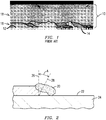
- FIG. 1 is a photomicrograph illustrating the result of a typical prior art weld cladding repair, showing a multi-layer clad region 10 deposited over a surface 12 of a directionally solidified substrate material 14.
- a lowermost portion 16 of the clad region 10 directionally solidified extensions of the substrate grains are highlighted in the figure with black lines.
- those grains terminate after a few layers of cladding and are covered by an uppermost portion 18 of the clad region 10 wherein recrystallization has occurred and the grains are no longer directionally solidified.
- FIG. 2 is a schematic illustration explaining how this occurs.
- FIG. 2 shows a profile view of a melt pool 20 of clad material progressing along a surface 22 of a directionally solidified substrate 24.
- the grains of the substrate 24 extend in a direction generally perpendicular to the surface 22 along substrate grain axis 26.
- solidification of the pool material actually occurs in a direction at a slight angle A inclined from the direction of the substrate grains along a solidification axis 28. If the solidification axis direction 28 is not excessively inclined to the substrate grain axis 26, the substrate grains will extend epitaxially (with the same crystallographic orientation) into the clad material.
- the first and often the second of such layers may advance the substrate grains a short distance, as illustrated in FIG. 1 .
- repeated processing of subsequent layers will inevitably encounter more preferred grain growth directions because solidification continues to be at an angle to the underlying microstructure, and other grain orientations are more favorably oriented to the direction of solidification 28.
- the result is that the directionally solidified or single crystal microstructure is no longer advanced, and recrystallization ensues in its place, as shown in the uppermost portion 18 of the clad region 10 of FIG. 1 .
- very crack sensitive alloys such as the nickel alloy sold under the trademarks MAR-M-247 or CM 247, deposit cracking initiates together with such changes in microstructure. This likely occurs because precipitations in such complex microstructures strain the newly oriented grain boundaries and thus initiate microcracks.
- the present inventor has innovatively developed an improved process for the repair of directionally solidified cast materials.
- the improved process overcomes the limitations of prior art processes by preserving the directionally solidified microstructure of the underlying substrate, extending that directional microstructure into the repair material, and allowing an essentially unlimited thickness of directionally solidified repair material to be added.
- FIG. 3 is a schematic illustration of one embodiment of the invention, where a directionally solidified (single crystal or columnar grained) gas turbine blade 30, seen in elevation view, is undergoing a material additive processes to repair its squealer tip 32.
- the term "squealer tip” is used in the art to describe an extension of the blade material along peripheral edges of the blade 30, as can be seen in FIG. 4 , which is a top view of blade 30 showing the location and geometry of the squealer tip 32, with other structures of FIG. 3 hidden.
- a squealer tip is designed to wear upon making intermittent contact with a shroud surrounding the blade during operation of a gas turbine engine.
- Repair of a squealer tip generally involves removing worn material, then building up a new tip with a material additive process.
- the blade 30 is submerged in a fluidized bed 34 of repair material powder.
- the fluidized bed 34 mobilizes powder onto the entire top surface process area of the squealer tip 32, while laser energy 36 is applied across the entire process area to melt the powder and fuse it to the underlying blade surface 38 in a continuous laser casting process.
- powder is fed into the fluidized bed 34 at a rate equal to the rate that it is being consumed in the process so that the level of powder remains essentially constant.
- the blade 30 is moved downward and away from the source of the laser energy 36 (as indicated by arrow 39), such that the active process surface remains approximately vertically stationary and the powder drift over the process plane is constant.
- the laser energy 36 may be applied by rapidly scanning or rastering a laser beam in two dimensions as necessary to heat the entire processing surface (i.e. entire top surface area of the squealer tip 32 as seen in FIG. 4 ).
- the heat conduction and solidification is effective to extend the substrate microstructure uniaxially and epitaxially without recrystallization.
- an inert gas such as argon as the mobilizing fluid in the fluidized bed 34, the blade 30 and melt surface 38 are also protected from undesirable atmospheric reactions such as oxidation and nitridation.
- the entire process interface is simultaneously under a continuous condition of melting and solidification exactly in the original cast direction, and is not being rebuilt incrementally across its surface with individually solidified passes of progression at an angle to the substrate grain orientation, thereby making possible the replication and extension of the substrate microstructure to any desired thickness.
- FIG. 4 is a plot of surface melting achieved on a bare steel substrate as a function of travel speed and laser power density. Extrapolating to lower travel speeds would suggest that laser power density of about 1 kW/cm 2 should produce melting at essentially zero travel speed, which represents the uniaxial laser casting process described above. With powder addition, energy loss from surface reflection will be reduced from the results of FIG. 5 because powder is known to act as an effective trap for laser light. Because the coupling of the laser beam will be more efficient, the melting of the powder and fusion to the substrate may be expected at power densities perhaps as low as 0.6 kW/cm 2 .
- the substrate is preheated, even lower power densities may be expected to sustain melting, perhaps as low as 0.4 kW/cm 2 .
- a commercially available 8 kW laser power source could be used to process a repair area of 20 cm 2 . That size is large compared to the size of a typical gas turbine blade platform repair, and is about the same as the top surface area of a typical gas turbine blade squealer tip 32.
- Lasers with even higher power capabilities are already known; for example, the Edison Welding Institute has demonstrated the use of a polygon optical scanner with a fiber laser at power levels up to 10 kW for a paint stripping application.
- High power diode or CO 2 lasers may be used with integrated or scanned optics in lieu of a rastered fiber laser beam, with the shape of the process area exposed to laser energy being controlled by the optics and/or masks to expose the entire process area to laser energy simultaneously.
- the present invention provides for the epitaxial extension of directionally solidified microstructures in superalloy materials for any repair area shape to an unlimited depth while avoiding recrystallization and cracking.
- the invention also requires less time than multiple pass processes while avoiding interpass temperature limitations and interpass cleaning concerns. Complex manipulation of the part being repaired is not required, since laser beam rastering distributes power over the process surface and the only other motion required is vertical part displacement relative to the laser beam.
- An apparatus for practicing the invention may include a means for mobilizing particles of material 34 over a process surface of a substrate 30; a means for applying energy 36 across the entire process surface in a manner effective to melt and fuse the material epitaxially onto the entire process surface simultaneously; and a means for providing relative motion 39 between the substrate and the means for mobilizing particles of material effective to maintain conditions for continuous epitaxial addition of the material to the substrate until a desired thickness of the material is added.
- the means for providing relative motion may be a motor driven platform or other mechanical device as would be known to one skilled in the art of fixturing.
- powder may be mobilized to move onto the process surface by means other than a fluidized bed, such as by a shaker system that oscillates the substrate or a container holding the particles, by applying acoustic, electric or magnetic energy to mobilize the particles, by the use of a broadcast spray system, etc.
- the part may be conditioned or heated before or after the material additive process by any variety of processes known in the art.
- the part may be insulated on its sides to more closely simulate heat conditions originally experienced during the original casting of the part.
- powder mesh ranges may be used in various applications to optimize particle movement and process results.
- the powder material and/or mesh range may be held constant or may be varied as the repair progresses.
- any combination of the particle supply, part and energy source may be moved relative to each other to maintain the continuous melt/fuse conditions with a solidification surface that is perpendicular to the direction of grain orientation and that is moving parallel to the direction of grain orientation.
- energy other than laser energy may be used, such as electro-magnetic or acoustic energy, so long as the energy source is capable of heating and melting the powder continuously over the entire process area.
Landscapes
- Engineering & Computer Science (AREA)
- Physics & Mathematics (AREA)
- Optics & Photonics (AREA)
- Mechanical Engineering (AREA)
- Plasma & Fusion (AREA)
- General Engineering & Computer Science (AREA)
- Laser Beam Processing (AREA)
- Powder Metallurgy (AREA)
- Turbine Rotor Nozzle Sealing (AREA)
- Other Surface Treatments For Metallic Materials (AREA)
- Recrystallisation Techniques (AREA)
Applications Claiming Priority (3)
| Application Number | Priority Date | Filing Date | Title |
|---|---|---|---|
| US201261645800P | 2012-05-11 | 2012-05-11 | |
| US13/658,866 US10415390B2 (en) | 2012-05-11 | 2012-10-24 | Repair of directionally solidified alloys |
| PCT/US2013/040562 WO2013170157A1 (en) | 2012-05-11 | 2013-05-10 | Repair of directionally solidified alloys |
Publications (2)
| Publication Number | Publication Date |
|---|---|
| EP2846957A1 EP2846957A1 (en) | 2015-03-18 |
| EP2846957B1 true EP2846957B1 (en) | 2018-11-07 |
Family
ID=49548826
Family Applications (1)
| Application Number | Title | Priority Date | Filing Date |
|---|---|---|---|
| EP13724136.0A Not-in-force EP2846957B1 (en) | 2012-05-11 | 2013-05-10 | Repair of directionally solidified alloys |
Country Status (8)
| Country | Link |
|---|---|
| US (1) | US10415390B2 (zh) |
| EP (1) | EP2846957B1 (zh) |
| JP (1) | JP6022679B2 (zh) |
| KR (1) | KR101774023B1 (zh) |
| CN (1) | CN104284752B (zh) |
| CA (1) | CA2870187C (zh) |
| RU (1) | RU2599322C2 (zh) |
| WO (1) | WO2013170157A1 (zh) |
Families Citing this family (14)
| Publication number | Priority date | Publication date | Assignee | Title |
|---|---|---|---|---|
| US9943933B2 (en) | 2013-03-15 | 2018-04-17 | Rolls-Royce Corporation | Repair of gas turbine engine components |
| EP3147067A1 (de) * | 2015-09-25 | 2017-03-29 | MTU Aero Engines GmbH | Vorrichtung und verfahren zur herstellung und/oder reparatur von, insbesondere rotationssymmetrischen, bauteilen |
| US10220471B2 (en) | 2015-10-14 | 2019-03-05 | Lawrence Livermore National Security, Llc | Spatter reduction laser scanning strategy in selective laser melting |
| LT6438B (lt) * | 2015-10-21 | 2017-08-25 | Uab "Neurotechnology" | Bekontakčio manipuliavimo įrenginys, surinkimo būdas ir 3d spausdinimas |
| US10583484B2 (en) | 2015-10-30 | 2020-03-10 | Seurat Technologies, Inc. | Multi-functional ingester system for additive manufacturing |
| DE102015225813A1 (de) * | 2015-12-17 | 2017-06-22 | Zf Friedrichshafen Ag | Verfahren und Vorrichtung zum Beschichten einer Oberfläche mit Molybdän |
| GB201600645D0 (en) * | 2016-01-13 | 2016-02-24 | Rolls Royce Plc | Improvements in additive layer manufacturing methods |
| US11701819B2 (en) | 2016-01-28 | 2023-07-18 | Seurat Technologies, Inc. | Additive manufacturing, spatial heat treating system and method |
| WO2017132668A1 (en) | 2016-01-29 | 2017-08-03 | Seurat Technologies, Inc. | Additive manufacturing, bond modifying system and method |
| KR102515643B1 (ko) | 2017-05-11 | 2023-03-30 | 쇠라 테크널러지스 인코포레이티드 | 적층 가공을 위한 패턴화된 광의 스위치야드 빔 라우팅 |
| KR20210104062A (ko) | 2018-12-19 | 2021-08-24 | 쇠라 테크널러지스 인코포레이티드 | 2차원 인쇄를 위해 펄스 변조 레이저를 사용하는 적층 제조 시스템 |
| JP7270428B2 (ja) * | 2019-03-19 | 2023-05-10 | 三菱重工業株式会社 | 一方向凝固物、タービン動翼及び一方向凝固物の補修方法 |
| JP7411991B2 (ja) | 2020-01-07 | 2024-01-12 | 株式会社キャンパスクリエイト | 熱可塑性樹脂成形体の溶着方法 |
| CN115070254A (zh) * | 2022-07-06 | 2022-09-20 | 郑州机械研究所有限公司 | 一种硬质合金钎焊用复合钎料及其制备方法 |
Citations (1)
| Publication number | Priority date | Publication date | Assignee | Title |
|---|---|---|---|---|
| EP0581548A1 (en) * | 1992-07-30 | 1994-02-02 | General Electric Company | Method for providing an extension on an end of an article having internal passageways |
Family Cites Families (25)
| Publication number | Priority date | Publication date | Assignee | Title |
|---|---|---|---|---|
| US4323756A (en) | 1979-10-29 | 1982-04-06 | United Technologies Corporation | Method for fabricating articles by sequential layer deposition |
| US4781770A (en) | 1986-03-24 | 1988-11-01 | Smith International, Inc. | Process for laser hardfacing drill bit cones having hard cutter inserts |
| US4818562A (en) * | 1987-03-04 | 1989-04-04 | Westinghouse Electric Corp. | Casting shapes |
| EP0289116A1 (en) | 1987-03-04 | 1988-11-02 | Westinghouse Electric Corporation | Method and device for casting powdered materials |
| US4878953A (en) | 1988-01-13 | 1989-11-07 | Metallurgical Industries, Inc. | Method of refurbishing cast gas turbine engine components and refurbished component |
| US5584663A (en) | 1994-08-15 | 1996-12-17 | General Electric Company | Environmentally-resistant turbine blade tip |
| US5914059A (en) | 1995-05-01 | 1999-06-22 | United Technologies Corporation | Method of repairing metallic articles by energy beam deposition with reduced power density |
| US5855149A (en) | 1996-11-18 | 1999-01-05 | National Research Council Of Canada | Process for producing a cutting die |
| US6049978A (en) | 1996-12-23 | 2000-04-18 | Recast Airfoil Group | Methods for repairing and reclassifying gas turbine engine airfoil parts |
| EP0861927A1 (de) * | 1997-02-24 | 1998-09-02 | Sulzer Innotec Ag | Verfahren zum Herstellen von einkristallinen Strukturen |
| US6331361B1 (en) | 1998-11-19 | 2001-12-18 | Hickham Industries, Inc. | Methods for manufacture and repair and resulting components with directionally solidified or single crystal materials |
| US6491207B1 (en) | 1999-12-10 | 2002-12-10 | General Electric Company | Weld repair of directionally solidified articles |
| US6503349B2 (en) * | 2001-05-15 | 2003-01-07 | United Technologies Corporation | Repair of single crystal nickel based superalloy article |
| CN1302156C (zh) | 2002-04-15 | 2007-02-28 | 西门子公司 | 制造单晶结构的方法 |
| EP1459871B1 (de) * | 2003-03-15 | 2011-04-06 | Evonik Degussa GmbH | Verfahren und Vorrichtung zur Herstellung von dreidimensionalen Objekten mittels Mikrowellenstrahlung sowie dadurch hergestellter Formkörper |
| JP4551082B2 (ja) | 2003-11-21 | 2010-09-22 | 三菱重工業株式会社 | 溶接方法 |
| RU2257285C1 (ru) | 2004-01-14 | 2005-07-27 | Открытое акционерное общество "Пермский моторный завод" | Способ наплавки жаропрочных высоколегированных сплавов |
| EP1561536A1 (de) | 2004-02-03 | 2005-08-10 | Siemens Aktiengesellschaft | Reparatur-Lotverfahren zum Reparieren eines Bauteils, welches ein Basismaterial mit einer gerichteten Mikrostruktur umfasst |
| US7034262B2 (en) | 2004-03-23 | 2006-04-25 | General Electric Company | Apparatus and methods for repairing tenons on turbine buckets |
| ATE537928T1 (de) | 2005-07-22 | 2012-01-15 | Siemens Ag | Verfahren zum reparieren eines mit einer gerichteten mikrostruktur umfassenden bauteils, durch einstellung während der elektron- oder der laser-wärmeeinwirkung eines temperaturgradient |
| US8353444B2 (en) * | 2005-10-28 | 2013-01-15 | United Technologies Corporation | Low temperature diffusion braze repair of single crystal components |
| US7784668B2 (en) * | 2005-12-16 | 2010-08-31 | United Technologies Corporation | Repair method for propagating epitaxial crystalline structures by heating to within 0-100° f of the solidus |
| RU2354523C1 (ru) | 2007-09-12 | 2009-05-10 | Федеральное государственное унитарное предприятие "Московское машиностроительное производственное предприятие "САЛЮТ" (ФГУП "ММПП "САЛЮТ") | Способ ремонта гребешков лабиринтных уплотнений рабочих лопаток турбины газотурбинного двигателя |
| JP2009288480A (ja) | 2008-05-29 | 2009-12-10 | Brother Ind Ltd | 画像形成装置 |
| DE102010049399A1 (de) | 2009-11-02 | 2011-05-26 | Alstom Technology Ltd. | Abrasive einkristalline Turbinenschaufel |
-
2012
- 2012-10-24 US US13/658,866 patent/US10415390B2/en not_active Expired - Fee Related
-
2013
- 2013-05-10 JP JP2015511757A patent/JP6022679B2/ja not_active Expired - Fee Related
- 2013-05-10 KR KR1020147034887A patent/KR101774023B1/ko active IP Right Grant
- 2013-05-10 WO PCT/US2013/040562 patent/WO2013170157A1/en active Application Filing
- 2013-05-10 EP EP13724136.0A patent/EP2846957B1/en not_active Not-in-force
- 2013-05-10 CN CN201380024429.8A patent/CN104284752B/zh not_active Expired - Fee Related
- 2013-05-10 RU RU2014145204/02A patent/RU2599322C2/ru active
- 2013-05-10 CA CA2870187A patent/CA2870187C/en not_active Expired - Fee Related
Patent Citations (1)
| Publication number | Priority date | Publication date | Assignee | Title |
|---|---|---|---|---|
| EP0581548A1 (en) * | 1992-07-30 | 1994-02-02 | General Electric Company | Method for providing an extension on an end of an article having internal passageways |
Also Published As
| Publication number | Publication date |
|---|---|
| JP6022679B2 (ja) | 2016-11-09 |
| RU2599322C2 (ru) | 2016-10-10 |
| WO2013170157A1 (en) | 2013-11-14 |
| CN104284752B (zh) | 2017-02-22 |
| US10415390B2 (en) | 2019-09-17 |
| US20130302533A1 (en) | 2013-11-14 |
| CA2870187C (en) | 2017-10-03 |
| CA2870187A1 (en) | 2013-11-14 |
| EP2846957A1 (en) | 2015-03-18 |
| RU2014145204A (ru) | 2016-07-10 |
| KR20150008486A (ko) | 2015-01-22 |
| CN104284752A (zh) | 2015-01-14 |
| KR101774023B1 (ko) | 2017-09-01 |
| JP2015521249A (ja) | 2015-07-27 |
Similar Documents
| Publication | Publication Date | Title |
|---|---|---|
| EP2846957B1 (en) | Repair of directionally solidified alloys | |
| EP0740976B1 (en) | Method of repairing single crystal metallic articles | |
| EP0740977B1 (en) | Containerless method of producing crack free metallic articles | |
| Rottwinkel et al. | Crack repair of single crystal turbine blades using laser cladding technology | |
| EP1424158B1 (en) | A method for fabricating, modifying or repairing of single crystal or directionally solidified articles | |
| EP1478482B1 (en) | Method of removing casting defects | |
| EP1798316B1 (en) | Repair method of crystalline structures by epitaxy | |
| US20050109818A1 (en) | Welding method | |
| US7306670B2 (en) | Method for producing monocrystalline structures | |
| US20160228990A1 (en) | Powder deposition process utilizing vibratory mechanical energy | |
| Rottwinkel et al. | Laser cladding for crack repair of CMSX-4 single-crystalline turbine parts | |
| JP2014042940A (ja) | レーザ肉盛溶接装置、肉盛溶接方法及び肉盛溶接部品 | |
| CA2897012C (en) | Laser deposition using a protrusion technique | |
| JP5835913B2 (ja) | 方向凝固材の溶接補修方法 | |
| WO2022232107A1 (en) | Method for welding gamma strengthened superalloys and other crack-prone materials | |
| WO2016209576A1 (en) | Repair welding method for superalloys |
Legal Events
| Date | Code | Title | Description |
|---|---|---|---|
| PUAI | Public reference made under article 153(3) epc to a published international application that has entered the european phase |
Free format text: ORIGINAL CODE: 0009012 |
|
| 17P | Request for examination filed |
Effective date: 20141007 |
|
| AK | Designated contracting states |
Kind code of ref document: A1 Designated state(s): AL AT BE BG CH CY CZ DE DK EE ES FI FR GB GR HR HU IE IS IT LI LT LU LV MC MK MT NL NO PL PT RO RS SE SI SK SM TR |
|
| AX | Request for extension of the european patent |
Extension state: BA ME |
|
| DAX | Request for extension of the european patent (deleted) | ||
| GRAP | Despatch of communication of intention to grant a patent |
Free format text: ORIGINAL CODE: EPIDOSNIGR1 |
|
| STAA | Information on the status of an ep patent application or granted ep patent |
Free format text: STATUS: GRANT OF PATENT IS INTENDED |
|
| INTG | Intention to grant announced |
Effective date: 20180727 |
|
| GRAS | Grant fee paid |
Free format text: ORIGINAL CODE: EPIDOSNIGR3 |
|
| GRAA | (expected) grant |
Free format text: ORIGINAL CODE: 0009210 |
|
| STAA | Information on the status of an ep patent application or granted ep patent |
Free format text: STATUS: THE PATENT HAS BEEN GRANTED |
|
| AK | Designated contracting states |
Kind code of ref document: B1 Designated state(s): AL AT BE BG CH CY CZ DE DK EE ES FI FR GB GR HR HU IE IS IT LI LT LU LV MC MK MT NL NO PL PT RO RS SE SI SK SM TR |
|
| REG | Reference to a national code |
Ref country code: GB Ref legal event code: FG4D |
|
| REG | Reference to a national code |
Ref country code: CH Ref legal event code: EP Ref country code: AT Ref legal event code: REF Ref document number: 1061490 Country of ref document: AT Kind code of ref document: T Effective date: 20181115 |
|
| REG | Reference to a national code |
Ref country code: IE Ref legal event code: FG4D |
|
| REG | Reference to a national code |
Ref country code: DE Ref legal event code: R096 Ref document number: 602013046275 Country of ref document: DE |
|
| REG | Reference to a national code |
Ref country code: NL Ref legal event code: MP Effective date: 20181107 |
|
| REG | Reference to a national code |
Ref country code: LT Ref legal event code: MG4D |
|
| REG | Reference to a national code |
Ref country code: AT Ref legal event code: MK05 Ref document number: 1061490 Country of ref document: AT Kind code of ref document: T Effective date: 20181107 |
|
| PG25 | Lapsed in a contracting state [announced via postgrant information from national office to epo] |
Ref country code: IS Free format text: LAPSE BECAUSE OF FAILURE TO SUBMIT A TRANSLATION OF THE DESCRIPTION OR TO PAY THE FEE WITHIN THE PRESCRIBED TIME-LIMIT Effective date: 20190307 Ref country code: LT Free format text: LAPSE BECAUSE OF FAILURE TO SUBMIT A TRANSLATION OF THE DESCRIPTION OR TO PAY THE FEE WITHIN THE PRESCRIBED TIME-LIMIT Effective date: 20181107 Ref country code: NO Free format text: LAPSE BECAUSE OF FAILURE TO SUBMIT A TRANSLATION OF THE DESCRIPTION OR TO PAY THE FEE WITHIN THE PRESCRIBED TIME-LIMIT Effective date: 20190207 Ref country code: BG Free format text: LAPSE BECAUSE OF FAILURE TO SUBMIT A TRANSLATION OF THE DESCRIPTION OR TO PAY THE FEE WITHIN THE PRESCRIBED TIME-LIMIT Effective date: 20190207 Ref country code: ES Free format text: LAPSE BECAUSE OF FAILURE TO SUBMIT A TRANSLATION OF THE DESCRIPTION OR TO PAY THE FEE WITHIN THE PRESCRIBED TIME-LIMIT Effective date: 20181107 Ref country code: LV Free format text: LAPSE BECAUSE OF FAILURE TO SUBMIT A TRANSLATION OF THE DESCRIPTION OR TO PAY THE FEE WITHIN THE PRESCRIBED TIME-LIMIT Effective date: 20181107 Ref country code: AT Free format text: LAPSE BECAUSE OF FAILURE TO SUBMIT A TRANSLATION OF THE DESCRIPTION OR TO PAY THE FEE WITHIN THE PRESCRIBED TIME-LIMIT Effective date: 20181107 Ref country code: HR Free format text: LAPSE BECAUSE OF FAILURE TO SUBMIT A TRANSLATION OF THE DESCRIPTION OR TO PAY THE FEE WITHIN THE PRESCRIBED TIME-LIMIT Effective date: 20181107 Ref country code: FI Free format text: LAPSE BECAUSE OF FAILURE TO SUBMIT A TRANSLATION OF THE DESCRIPTION OR TO PAY THE FEE WITHIN THE PRESCRIBED TIME-LIMIT Effective date: 20181107 |
|
| PG25 | Lapsed in a contracting state [announced via postgrant information from national office to epo] |
Ref country code: PT Free format text: LAPSE BECAUSE OF FAILURE TO SUBMIT A TRANSLATION OF THE DESCRIPTION OR TO PAY THE FEE WITHIN THE PRESCRIBED TIME-LIMIT Effective date: 20190307 Ref country code: SE Free format text: LAPSE BECAUSE OF FAILURE TO SUBMIT A TRANSLATION OF THE DESCRIPTION OR TO PAY THE FEE WITHIN THE PRESCRIBED TIME-LIMIT Effective date: 20181107 Ref country code: AL Free format text: LAPSE BECAUSE OF FAILURE TO SUBMIT A TRANSLATION OF THE DESCRIPTION OR TO PAY THE FEE WITHIN THE PRESCRIBED TIME-LIMIT Effective date: 20181107 Ref country code: RS Free format text: LAPSE BECAUSE OF FAILURE TO SUBMIT A TRANSLATION OF THE DESCRIPTION OR TO PAY THE FEE WITHIN THE PRESCRIBED TIME-LIMIT Effective date: 20181107 Ref country code: GR Free format text: LAPSE BECAUSE OF FAILURE TO SUBMIT A TRANSLATION OF THE DESCRIPTION OR TO PAY THE FEE WITHIN THE PRESCRIBED TIME-LIMIT Effective date: 20190208 Ref country code: NL Free format text: LAPSE BECAUSE OF FAILURE TO SUBMIT A TRANSLATION OF THE DESCRIPTION OR TO PAY THE FEE WITHIN THE PRESCRIBED TIME-LIMIT Effective date: 20181107 |
|
| PG25 | Lapsed in a contracting state [announced via postgrant information from national office to epo] |
Ref country code: DK Free format text: LAPSE BECAUSE OF FAILURE TO SUBMIT A TRANSLATION OF THE DESCRIPTION OR TO PAY THE FEE WITHIN THE PRESCRIBED TIME-LIMIT Effective date: 20181107 Ref country code: PL Free format text: LAPSE BECAUSE OF FAILURE TO SUBMIT A TRANSLATION OF THE DESCRIPTION OR TO PAY THE FEE WITHIN THE PRESCRIBED TIME-LIMIT Effective date: 20181107 Ref country code: CZ Free format text: LAPSE BECAUSE OF FAILURE TO SUBMIT A TRANSLATION OF THE DESCRIPTION OR TO PAY THE FEE WITHIN THE PRESCRIBED TIME-LIMIT Effective date: 20181107 |
|
| REG | Reference to a national code |
Ref country code: DE Ref legal event code: R097 Ref document number: 602013046275 Country of ref document: DE |
|
| PG25 | Lapsed in a contracting state [announced via postgrant information from national office to epo] |
Ref country code: EE Free format text: LAPSE BECAUSE OF FAILURE TO SUBMIT A TRANSLATION OF THE DESCRIPTION OR TO PAY THE FEE WITHIN THE PRESCRIBED TIME-LIMIT Effective date: 20181107 Ref country code: RO Free format text: LAPSE BECAUSE OF FAILURE TO SUBMIT A TRANSLATION OF THE DESCRIPTION OR TO PAY THE FEE WITHIN THE PRESCRIBED TIME-LIMIT Effective date: 20181107 Ref country code: SK Free format text: LAPSE BECAUSE OF FAILURE TO SUBMIT A TRANSLATION OF THE DESCRIPTION OR TO PAY THE FEE WITHIN THE PRESCRIBED TIME-LIMIT Effective date: 20181107 Ref country code: SM Free format text: LAPSE BECAUSE OF FAILURE TO SUBMIT A TRANSLATION OF THE DESCRIPTION OR TO PAY THE FEE WITHIN THE PRESCRIBED TIME-LIMIT Effective date: 20181107 |
|
| PLBE | No opposition filed within time limit |
Free format text: ORIGINAL CODE: 0009261 |
|
| STAA | Information on the status of an ep patent application or granted ep patent |
Free format text: STATUS: NO OPPOSITION FILED WITHIN TIME LIMIT |
|
| 26N | No opposition filed |
Effective date: 20190808 |
|
| PG25 | Lapsed in a contracting state [announced via postgrant information from national office to epo] |
Ref country code: SI Free format text: LAPSE BECAUSE OF FAILURE TO SUBMIT A TRANSLATION OF THE DESCRIPTION OR TO PAY THE FEE WITHIN THE PRESCRIBED TIME-LIMIT Effective date: 20181107 |
|
| REG | Reference to a national code |
Ref country code: CH Ref legal event code: PL |
|
| GBPC | Gb: european patent ceased through non-payment of renewal fee |
Effective date: 20190510 |
|
| PG25 | Lapsed in a contracting state [announced via postgrant information from national office to epo] |
Ref country code: LI Free format text: LAPSE BECAUSE OF NON-PAYMENT OF DUE FEES Effective date: 20190531 Ref country code: CH Free format text: LAPSE BECAUSE OF NON-PAYMENT OF DUE FEES Effective date: 20190531 Ref country code: MC Free format text: LAPSE BECAUSE OF FAILURE TO SUBMIT A TRANSLATION OF THE DESCRIPTION OR TO PAY THE FEE WITHIN THE PRESCRIBED TIME-LIMIT Effective date: 20181107 |
|
| REG | Reference to a national code |
Ref country code: BE Ref legal event code: MM Effective date: 20190531 |
|
| PG25 | Lapsed in a contracting state [announced via postgrant information from national office to epo] |
Ref country code: LU Free format text: LAPSE BECAUSE OF NON-PAYMENT OF DUE FEES Effective date: 20190510 |
|
| PG25 | Lapsed in a contracting state [announced via postgrant information from national office to epo] |
Ref country code: TR Free format text: LAPSE BECAUSE OF FAILURE TO SUBMIT A TRANSLATION OF THE DESCRIPTION OR TO PAY THE FEE WITHIN THE PRESCRIBED TIME-LIMIT Effective date: 20181107 |
|
| PG25 | Lapsed in a contracting state [announced via postgrant information from national office to epo] |
Ref country code: IE Free format text: LAPSE BECAUSE OF NON-PAYMENT OF DUE FEES Effective date: 20190510 Ref country code: GB Free format text: LAPSE BECAUSE OF NON-PAYMENT OF DUE FEES Effective date: 20190510 |
|
| PG25 | Lapsed in a contracting state [announced via postgrant information from national office to epo] |
Ref country code: BE Free format text: LAPSE BECAUSE OF NON-PAYMENT OF DUE FEES Effective date: 20190531 |
|
| PGFP | Annual fee paid to national office [announced via postgrant information from national office to epo] |
Ref country code: FR Payment date: 20200518 Year of fee payment: 8 |
|
| PGFP | Annual fee paid to national office [announced via postgrant information from national office to epo] |
Ref country code: IT Payment date: 20200525 Year of fee payment: 8 |
|
| PGFP | Annual fee paid to national office [announced via postgrant information from national office to epo] |
Ref country code: DE Payment date: 20200720 Year of fee payment: 8 |
|
| PG25 | Lapsed in a contracting state [announced via postgrant information from national office to epo] |
Ref country code: CY Free format text: LAPSE BECAUSE OF FAILURE TO SUBMIT A TRANSLATION OF THE DESCRIPTION OR TO PAY THE FEE WITHIN THE PRESCRIBED TIME-LIMIT Effective date: 20181107 |
|
| PG25 | Lapsed in a contracting state [announced via postgrant information from national office to epo] |
Ref country code: HU Free format text: LAPSE BECAUSE OF FAILURE TO SUBMIT A TRANSLATION OF THE DESCRIPTION OR TO PAY THE FEE WITHIN THE PRESCRIBED TIME-LIMIT; INVALID AB INITIO Effective date: 20130510 Ref country code: MT Free format text: LAPSE BECAUSE OF FAILURE TO SUBMIT A TRANSLATION OF THE DESCRIPTION OR TO PAY THE FEE WITHIN THE PRESCRIBED TIME-LIMIT Effective date: 20181107 |
|
| REG | Reference to a national code |
Ref country code: DE Ref legal event code: R119 Ref document number: 602013046275 Country of ref document: DE |
|
| PG25 | Lapsed in a contracting state [announced via postgrant information from national office to epo] |
Ref country code: DE Free format text: LAPSE BECAUSE OF NON-PAYMENT OF DUE FEES Effective date: 20211201 |
|
| PG25 | Lapsed in a contracting state [announced via postgrant information from national office to epo] |
Ref country code: FR Free format text: LAPSE BECAUSE OF NON-PAYMENT OF DUE FEES Effective date: 20210531 |
|
| PG25 | Lapsed in a contracting state [announced via postgrant information from national office to epo] |
Ref country code: MK Free format text: LAPSE BECAUSE OF FAILURE TO SUBMIT A TRANSLATION OF THE DESCRIPTION OR TO PAY THE FEE WITHIN THE PRESCRIBED TIME-LIMIT Effective date: 20181107 |
|
| PG25 | Lapsed in a contracting state [announced via postgrant information from national office to epo] |
Ref country code: IT Free format text: LAPSE BECAUSE OF NON-PAYMENT OF DUE FEES Effective date: 20200510 |