EP2846137B1 - Clip-in support ring - Google Patents
Clip-in support ring Download PDFInfo
- Publication number
- EP2846137B1 EP2846137B1 EP14183465.5A EP14183465A EP2846137B1 EP 2846137 B1 EP2846137 B1 EP 2846137B1 EP 14183465 A EP14183465 A EP 14183465A EP 2846137 B1 EP2846137 B1 EP 2846137B1
- Authority
- EP
- European Patent Office
- Prior art keywords
- support ring
- clip
- ema
- housing
- arm
- Prior art date
- Legal status (The legal status is an assumption and is not a legal conclusion. Google has not performed a legal analysis and makes no representation as to the accuracy of the status listed.)
- Active
Links
- 238000000034 method Methods 0.000 description 6
- 238000005452 bending Methods 0.000 description 3
- 239000004020 conductor Substances 0.000 description 3
- 230000007613 environmental effect Effects 0.000 description 3
- 238000003466 welding Methods 0.000 description 3
- 238000001514 detection method Methods 0.000 description 2
- 230000006870 function Effects 0.000 description 2
- BQCADISMDOOEFD-UHFFFAOYSA-N Silver Chemical compound [Ag] BQCADISMDOOEFD-UHFFFAOYSA-N 0.000 description 1
- 239000003990 capacitor Substances 0.000 description 1
- 239000000356 contaminant Substances 0.000 description 1
- 230000014759 maintenance of location Effects 0.000 description 1
- 229910052751 metal Inorganic materials 0.000 description 1
- 239000002184 metal Substances 0.000 description 1
- 238000012986 modification Methods 0.000 description 1
- 230000004048 modification Effects 0.000 description 1
- 238000007747 plating Methods 0.000 description 1
- 229910052709 silver Inorganic materials 0.000 description 1
- 239000004332 silver Substances 0.000 description 1
Images


Classifications
-
- F—MECHANICAL ENGINEERING; LIGHTING; HEATING; WEAPONS; BLASTING
- F16—ENGINEERING ELEMENTS AND UNITS; GENERAL MEASURES FOR PRODUCING AND MAINTAINING EFFECTIVE FUNCTIONING OF MACHINES OR INSTALLATIONS; THERMAL INSULATION IN GENERAL
- F16M—FRAMES, CASINGS OR BEDS OF ENGINES, MACHINES OR APPARATUS, NOT SPECIFIC TO ENGINES, MACHINES OR APPARATUS PROVIDED FOR ELSEWHERE; STANDS; SUPPORTS
- F16M13/00—Other supports for positioning apparatus or articles; Means for steadying hand-held apparatus or articles
- F16M13/02—Other supports for positioning apparatus or articles; Means for steadying hand-held apparatus or articles for supporting on, or attaching to, an object, e.g. tree, gate, window-frame, cycle
-
- G—PHYSICS
- G01—MEASURING; TESTING
- G01D—MEASURING NOT SPECIALLY ADAPTED FOR A SPECIFIC VARIABLE; ARRANGEMENTS FOR MEASURING TWO OR MORE VARIABLES NOT COVERED IN A SINGLE OTHER SUBCLASS; TARIFF METERING APPARATUS; MEASURING OR TESTING NOT OTHERWISE PROVIDED FOR
- G01D11/00—Component parts of measuring arrangements not specially adapted for a specific variable
- G01D11/24—Housings ; Casings for instruments
- G01D11/245—Housings for sensors
-
- B—PERFORMING OPERATIONS; TRANSPORTING
- B23—MACHINE TOOLS; METAL-WORKING NOT OTHERWISE PROVIDED FOR
- B23K—SOLDERING OR UNSOLDERING; WELDING; CLADDING OR PLATING BY SOLDERING OR WELDING; CUTTING BY APPLYING HEAT LOCALLY, e.g. FLAME CUTTING; WORKING BY LASER BEAM
- B23K1/00—Soldering, e.g. brazing, or unsoldering
- B23K1/0008—Soldering, e.g. brazing, or unsoldering specially adapted for particular articles or work
-
- B—PERFORMING OPERATIONS; TRANSPORTING
- B23—MACHINE TOOLS; METAL-WORKING NOT OTHERWISE PROVIDED FOR
- B23K—SOLDERING OR UNSOLDERING; WELDING; CLADDING OR PLATING BY SOLDERING OR WELDING; CUTTING BY APPLYING HEAT LOCALLY, e.g. FLAME CUTTING; WORKING BY LASER BEAM
- B23K15/00—Electron-beam welding or cutting
- B23K15/0046—Welding
- B23K15/008—Spot welding
-
- G—PHYSICS
- G01—MEASURING; TESTING
- G01L—MEASURING FORCE, STRESS, TORQUE, WORK, MECHANICAL POWER, MECHANICAL EFFICIENCY, OR FLUID PRESSURE
- G01L1/00—Measuring force or stress, in general
- G01L1/20—Measuring force or stress, in general by measuring variations in ohmic resistance of solid materials or of electrically-conductive fluids; by making use of electrokinetic cells, i.e. liquid-containing cells wherein an electrical potential is produced or varied upon the application of stress
- G01L1/22—Measuring force or stress, in general by measuring variations in ohmic resistance of solid materials or of electrically-conductive fluids; by making use of electrokinetic cells, i.e. liquid-containing cells wherein an electrical potential is produced or varied upon the application of stress using resistance strain gauges
- G01L1/2287—Measuring force or stress, in general by measuring variations in ohmic resistance of solid materials or of electrically-conductive fluids; by making use of electrokinetic cells, i.e. liquid-containing cells wherein an electrical potential is produced or varied upon the application of stress using resistance strain gauges constructional details of the strain gauges
-
- Y—GENERAL TAGGING OF NEW TECHNOLOGICAL DEVELOPMENTS; GENERAL TAGGING OF CROSS-SECTIONAL TECHNOLOGIES SPANNING OVER SEVERAL SECTIONS OF THE IPC; TECHNICAL SUBJECTS COVERED BY FORMER USPC CROSS-REFERENCE ART COLLECTIONS [XRACs] AND DIGESTS
- Y10—TECHNICAL SUBJECTS COVERED BY FORMER USPC
- Y10T—TECHNICAL SUBJECTS COVERED BY FORMER US CLASSIFICATION
- Y10T403/00—Joints and connections
- Y10T403/47—Molded joint
- Y10T403/477—Fusion bond, e.g., weld, etc.
Definitions
- the present invention relates to a clip-in support ring.
- US2002/0096618 discloses a mounting assembly for a detection device.
- the mounting assembly has an attachment plate on which the detection device is held.
- An elastic retainer on one side of the plate biases the device a against a stop slip on the opposite side of the plate, constraining the device in an x-direction parallel to the plate.
- a pair of opposite side lips of the plate constrain it a y-direction parallel to the plate.
- the device In the z-direction perpendicular to the plate the device is constrained by elastic tabs protruding from the stop lip into recesses in the device and on the opposite by a pin of the device projecting into an orifice of the elastic retainer.
- a support ring comprising:
- the support ring may further comprise:
- the first beam and the second beam may be flexible.
- the spring force provided by the arm may include a force in a lateral direction with respect to a primary plane of the support ring.
- the spring force provided by the arm may include a force in a downward direction with respect to a primary plane of the support ring.
- the hook may extend upward from the support ring.
- the support ring may further comprise: a leg that extends downward from the support ring.
- the leg may be a dimple.
- the support ring may be affixed to a housing of a sensor device.
- the affixed support ring may provide electrical continuity between the housing and the EMA.
- the sensor device may include a micro-strain gauge (MSG).
- MSG micro-strain gauge
- the support ring may be is affixed to the housing by a spot weld.
- a sensor device such as, for example, a micro-strain gauge (MSG) device, may have an electronic module assembly (EMA).
- the EMA may be mechanically fixed above a diaphragm in the sensor device for wire-bonding.
- the EMA may be connected electrically to a housing associated with the sensor device for electromagnetic compatibility (EMC) performance.
- EMC electromagnetic compatibility
- Clip-in support rings described herein may be used to provide these functions in a device such as, for example, a sensor device.
- the clip-in support rings may, for example, provide fixation of the EMA by way of a spring force and a reaction force.
- affixing e.g., spot welding
- a clip-in support ring described herein to a housing of the device may, for example, provide a robust mechanical and/or electrical connection to the housing.
- the electrical connection may provide electrical continuity between the EMA and the housing.
- FIG. 1 illustrates an example embodiment of a sensor device 100 having an EMA 140 and a clip-in support ring 200.
- sensor device 100 may include, for example, a connector 110, one or more contact springs 120, an environmental seal 130, EMA 140, clip-in support ring 200, a housing 160, and a sense element assembly 170.
- the connector 110 may connect the sensor device 100 with an external source (e.g., an external computer).
- Connector 110 may include a terminal that may make, for example, electrical contact with an electrical conductor (e.g., an electrical wire) that may be connected to the external source.
- the terminal may, for example, be used to transfer signals that may be produced by the sensor device 100 to the external source via the electrical conductor.
- the signals may include, for example, sensor readings that may be made by the sensor device 100.
- Contact springs 120 may provide electrical continuity between EMA 140 and, for example, a terminal contained in connector 110.
- Contact springs 120 may include an electrically conductive material (e.g., silver plating) that may be used to provide the electrical continuity.
- Environmental seal 130 may provide a seal between, for example, connector 110 and housing 160.
- Environmental seal 130 may prevent, for example, contaminants (e.g., moisture, dirt), that may potentially affect a performance of the sensor device 100, from entering the sensor device 100.
- EMA 140 may include, for example, a circuit board and one or more electronic components 142 (e.g., integrated circuits, transistors, resistors, capacitors, inductors, diodes).
- the circuit board may be a printed circuit board (PCB).
- the electronic components may be mounted on the circuit board.
- the electronic components may, for example, process conditions (e.g., forces) sensed by sense element assembly 170 and/or generate signals based on the sensed conditions.
- the electronic components may include components that may transfer the generated signals to an external source via a terminal that may be contained in connector 110.
- Housing 160 may provide a mounting platform for the clip-in support ring 200.
- Housing 160 may be made of a metal that may enable clip-in support ring 200 to be affixed (e.g., welded) to the housing 160.
- housing 160 is shaped as a hexagonal cup.
- Sense element assembly 170 may include provisions for sensing conditions such as, for example, conditions applied to the sensor device 100.
- Sense element assembly 170 may include for example, strain gauges 172 that may be used to sense various forces that may be applied to the sensor device 100.
- Conditions sensed by sense element assembly 170 may be detected by circuitry contained on EMA 140.
- the circuitry may process the sensed conditions and generate various signals based on the processed sensed conditions.
- the signals may be transferred from the sensor device 100 to an external source via a terminal contained in connector 110.
- Clip-in support ring 200 may be a support ring that may secure EMA 140 in sensor device 100. Specifically, EMA 140 may be loaded onto clip-in support ring 200. Afterwards, clip-in support ring 200 may be affixed to housing 160, thereby, providing a secure support for EMA 140 in sensor device 100.
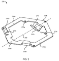
- FIG. 2 illustrates an example embodiment of clip-in support ring 200.
- clip-in support ring 200 may include, for example, hooks 220a-b, beams 230a-b, an arm 240, a first end 250a, a second end 250b, and pedestals 270a-c.
- Plane 260 may illustrate a primary plane of the clip-in support ring 200.
- clip-in support ring 200 may include other features.
- clip-in support ring 200 may include one or more legs.
- the legs may extend (e.g., protrude) downward from clip-in support ring 200.
- the legs may, for example, support clip-in support ring 200 when the clip-in support ring 200 is affixed to housing 160.
- the legs may make contact with housing 160 and provide electrical continuity between EMA 140 (after being loaded in clip-in support ring 200) and housing 160. Examples of legs that may be used with clip-in support ring 200 will be described further below.
- Hooks 220a-b may extend upward from clip-in support ring 200 at the first end 250a.
- Hooks 220a-b may provide a force to EMA 140 that in combination with a force provided by arm 240 may hold EMA 140 in place in the clip-in support ring 200.
- the force provided by hooks 220a-b may be, for example, a reaction force that may be applied to EMA 140 in response to a spring force that may be applied to EMA 140 by arm 240.
- clip-in support ring 200 may include other numbers of hooks 220.
- clip-in support ring 200 may include one hook 220 or more than two hooks 220.
- Beams 230a-b may be in plane 260 and located between the first end 250a and the second end 250b. Beams 230a-b may have widths that are smaller than widths of the first end 250a and/or the second end 250b. Beams 230a-b may be compliant (e.g., flexible) and may provide a reaction force to EMA 140 after the EMA 140 is loaded in clip-in support ring 200. A flexibility of beams 230a-b may, however, be restricted (e.g., locked out) after, for example, the clip-in support ring 200 is loaded with EMA 140 and the clip-in support ring 200 is affixed to housing 160.
- compliant e.g., flexible
- a flexibility of beams 230a-b may, however, be restricted (e.g., locked out) after, for example, the clip-in support ring 200 is loaded with EMA 140 and the clip-in support ring 200 is affixed to housing 160.
- Arm 240 may be located at the second end 250b.
- Arm 240 may include a first portion 242a and a second portion 242b.
- the first portion 242a may extend downwards from plane 260.
- the second portion 242b may extend upwards from an end of the first portion 242a and cross plane 260 to extend upward above plane 260.
- the first portion 242a and second portion 242b may be shaped to form a "V". It should be noted, however, that in other embodiments, the first portion 242a and the second portion 242b may be shaped to form other shapes (e.g., a semi-circle).
- Arm 240 may be compliant and may provide a spring force that may act as a clamping force for holding EMA 140 in place after the EMA 140 is loaded in the clip-in support ring 200.
- clip-in support ring 200 may include other numbers of arms 240.
- other embodiments of clip-in support ring 200 may include multiple arms 240.
- arms 240 in other embodiments of clip-in support ring 200 may be shaped differently than illustrated in FIG. 2 .
- Pedestals 270a-b may provide, for example, support for EMA 140 after EMA 140 is loaded in clip-in support ring 200. Moreover, pedestals 270a-b may be provide electrical continuity between EMA 140 and clip-in support ring 200.
- clip-in support ring 200 may be affixed to housing 160. Affixing clip-in support ring 200 to housing 160 may provide electrical continuity between EMA 140 and housing 160 via clip-in support ring 200. The electrical continuity may be provided, for example, via pedestals (e.g., pedestals 270a-b) and/or legs that may be contained on clip-in support ring 200.
- pedestals e.g., pedestals 270a-b
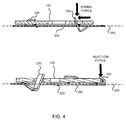
- FIG. 3 illustrates an example placement of EMA 140 in clip-in support ring 200 and FIG. 4 illustrates an operation of clip-in support ring 200.
- a first end of EMA 140 may, for example, include an opening to accommodate arm 240.
- a second end of EMA 140 may, for example, be notched to accommodate hooks 220a-b.
- arm 240 and hooks 220a-b may provide one or more forces that may be used to secure EMA 140 to clip-in support ring 200.
- arm 240 may provide a spring force on the first end of the EMA 140.
- the spring force may include one or more forces.
- the spring force may include a force in a lateral direction with respect to plane 260 and/or a force in a downward direction with respect to plane 260.
- the spring force may be achieved by two compliant features of the clip-in support ring 200 in series.
- a first feature may include the compliant beams 230a-b and a second feature in series with the first feature may include the stiffer formed yet compliant arm 240.
- Hooks 220a-b may provide a reaction force on a second end of the EMA 140 opposite the first end of the EMA 140.
- the reaction force may be in reaction to the spring force provided by the arm 240.
- a combination of the spring and reaction forces may secure the EMA 140 in the clip-in support ring 200.
- Loading EMA 140 in clip-in support ring 200 may be achieved, for example, by bending (e.g., bending in) plane 260 of the clip-in support ring 200, which may be facilitated by beams 230a-b.
- a sub-assembly process may include a fixture that may first bend the clip-in support ring 200 along the beams 230a-b and then actuate or rotate arm 240 to obtain the situation of FIG. 3 .
- clip-in support ring 200 may include one or more legs.
- An example of legs that may be used with clip-in support ring 200 include legs 420.
- Legs 420 may be shaped, for example, as dimples that may extend downward from clip-in support ring 200. The dimples may make contact with housing 160 after clip-in support ring 200 is placed in housing 160.
- legs 420 illustrated in FIG. 4 are an example of a type of leg that may be used with clip-in support ring 200.
- Other embodiments of clip-in support ring 200 may include other types of legs.
- an embodiment of clip-in support ring 200 may include one or more prongs that may perform the function of legs 420.
- the clip-in support ring 200 may be affixed (e.g., spot welded) to housing 160. Affixing the clip-in support ring 200 to housing 160 may obviate bending of the beam 230a-b and may result in a retention force that may keep the EMA 140 in place over an expected life of the sensor device 100.
- FIG. 5 illustrates an example technique for affixing the clip-in support ring 200 to housing 160 after the clip-in support ring 200 is loaded with EMA 140.
- the clip-in support ring 200 may be secured to the housing 160 by spot welding the clip-in support ring 200 to the housing 160 at various points 510a-c.
- points 510a-c are examples of points where clip-in support ring 200 may be spot welded to housing 160.
- clip-in support ring 200 may be secured to housing 160 at other points on the clip-in support ring 200.
- clip-in support ring 200 may be secured to housing 160 using techniques other than spot welding.
Landscapes
- Engineering & Computer Science (AREA)
- Mechanical Engineering (AREA)
- Physics & Mathematics (AREA)
- General Physics & Mathematics (AREA)
- General Engineering & Computer Science (AREA)
- Snaps, Bayonet Connections, Set Pins, And Snap Rings (AREA)
- Clamps And Clips (AREA)
- Connection Of Plates (AREA)
- Mounting Of Printed Circuit Boards And The Like (AREA)
- Measuring Leads Or Probes (AREA)
- Measurement Of Length, Angles, Or The Like Using Electric Or Magnetic Means (AREA)
- Hooks, Suction Cups, And Attachment By Adhesive Means (AREA)
- Pressure Sensors (AREA)
Description
- The present invention relates to a clip-in support ring.
-
US2002/0096618 discloses a mounting assembly for a detection device. The mounting assembly has an attachment plate on which the detection device is held. An elastic retainer on one side of the plate biases the device a against a stop slip on the opposite side of the plate, constraining the device in an x-direction parallel to the plate. A pair of opposite side lips of the plate constrain it a y-direction parallel to the plate. In the z-direction perpendicular to the plate the device is constrained by elastic tabs protruding from the stop lip into recesses in the device and on the opposite by a pin of the device projecting into an orifice of the elastic retainer. - According to the present invention there is provided a support ring comprising:
- an electronic module assembly -EMA loaded in the support ring, the EMA having one or more electronic components for processing one or more conditions sensed by a sense element assembly,
- an arm at a first end of the support ring, the arm providing a spring force to the EMA, the arm including:
- a first portion that extends downwards from a primary plane of the support ring, and
- a second portion that extends upwards crossing the primary plane of the support ring; and
- a hook at a second end of the support ring, the second end being opposite the first end, the hook providing a reaction force to the EMA that is in reaction to the spring force.
- The support ring may further comprise:
- a first beam; and
- a second beam,
- The first beam and the second beam may be flexible.
- The spring force provided by the arm may include a force in a lateral direction with respect to a primary plane of the support ring. The spring force provided by the arm may include a force in a downward direction with respect to a primary plane of the support ring.
- The hook may extend upward from the support ring.
- The support ring may further comprise: a leg that extends downward from the support ring. The leg may be a dimple.
- The support ring may be affixed to a housing of a sensor device. The affixed support ring may provide electrical continuity between the housing and the EMA. The sensor device may include a micro-strain gauge (MSG). The support ring may be is affixed to the housing by a spot weld.
- The accompanying drawings, which are incorporated in and constitute a part of this specification, illustrate one or more embodiments described herein and, together with the description, explain these embodiments. In the drawings:
-
FIG. 1 illustrates an example embodiment of a sensor device having an electronics module assembly (EMA) and a clip-in support ring; -
FIG. 2 illustrates an example embodiment of a clip-in support ring that may be contained in the sensor device illustrated inFIG. 1 ; -
FIG. 3 illustrates an example placement of an EMA in the clip-in support ring; -
FIG. 4 illustrates an example operation of the clip-in support ring; and -
FIG. 5 illustrates an example technique for securing the clip-in support ring to a housing that may be contained in the sensor device illustrated inFIG. 1 . - A sensor device such as, for example, a micro-strain gauge (MSG) device, may have an electronic module assembly (EMA). The EMA may be mechanically fixed above a diaphragm in the sensor device for wire-bonding. The EMA may be connected electrically to a housing associated with the sensor device for electromagnetic compatibility (EMC) performance.
- Clip-in support rings described herein may be used to provide these functions in a device such as, for example, a sensor device. The clip-in support rings may, for example, provide fixation of the EMA by way of a spring force and a reaction force. Moreover, affixing (e.g., spot welding) a clip-in support ring described herein to a housing of the device may, for example, provide a robust mechanical and/or electrical connection to the housing. The electrical connection may provide electrical continuity between the EMA and the housing.
-
FIG. 1 illustrates an example embodiment of asensor device 100 having an EMA 140 and a clip-insupport ring 200. Referring toFIG. 1 ,sensor device 100 may include, for example, aconnector 110, one ormore contact springs 120, anenvironmental seal 130, EMA 140, clip-insupport ring 200, ahousing 160, and asense element assembly 170. - The
connector 110 may connect thesensor device 100 with an external source (e.g., an external computer).Connector 110 may include a terminal that may make, for example, electrical contact with an electrical conductor (e.g., an electrical wire) that may be connected to the external source. The terminal may, for example, be used to transfer signals that may be produced by thesensor device 100 to the external source via the electrical conductor. The signals may include, for example, sensor readings that may be made by thesensor device 100. -
Contact springs 120 may provide electrical continuity between EMA 140 and, for example, a terminal contained inconnector 110. Contactsprings 120 may include an electrically conductive material (e.g., silver plating) that may be used to provide the electrical continuity. -
Environmental seal 130 may provide a seal between, for example,connector 110 andhousing 160.Environmental seal 130 may prevent, for example, contaminants (e.g., moisture, dirt), that may potentially affect a performance of thesensor device 100, from entering thesensor device 100. - EMA 140 may include, for example, a circuit board and one or more electronic components 142 (e.g., integrated circuits, transistors, resistors, capacitors, inductors, diodes). The circuit board may be a printed circuit board (PCB). The electronic components may be mounted on the circuit board. The electronic components may, for example, process conditions (e.g., forces) sensed by
sense element assembly 170 and/or generate signals based on the sensed conditions. The electronic components may include components that may transfer the generated signals to an external source via a terminal that may be contained inconnector 110. -
Housing 160 may provide a mounting platform for the clip-insupport ring 200.Housing 160 may be made of a metal that may enable clip-insupport ring 200 to be affixed (e.g., welded) to thehousing 160. In an embodiment,housing 160 is shaped as a hexagonal cup. -
Sense element assembly 170 may include provisions for sensing conditions such as, for example, conditions applied to thesensor device 100.Sense element assembly 170 may include for example,strain gauges 172 that may be used to sense various forces that may be applied to thesensor device 100. - Conditions sensed by
sense element assembly 170 may be detected by circuitry contained onEMA 140. The circuitry may process the sensed conditions and generate various signals based on the processed sensed conditions. The signals may be transferred from thesensor device 100 to an external source via a terminal contained inconnector 110. - Clip-in
support ring 200 may be a support ring that may secureEMA 140 insensor device 100. Specifically,EMA 140 may be loaded onto clip-insupport ring 200. Afterwards, clip-insupport ring 200 may be affixed tohousing 160, thereby, providing a secure support forEMA 140 insensor device 100. -
FIG. 2 illustrates an example embodiment of clip-insupport ring 200. Referring toFIG. 2 , clip-insupport ring 200 may include, for example, hooks 220a-b, beams 230a-b, anarm 240, afirst end 250a, asecond end 250b, andpedestals 270a-c.Plane 260 may illustrate a primary plane of the clip-insupport ring 200. - It should be noted that clip-in
support ring 200 may include other features. For example, clip-insupport ring 200 may include one or more legs. The legs may extend (e.g., protrude) downward from clip-insupport ring 200. The legs may, for example, support clip-insupport ring 200 when the clip-insupport ring 200 is affixed tohousing 160. The legs may make contact withhousing 160 and provide electrical continuity between EMA 140 (after being loaded in clip-in support ring 200) andhousing 160. Examples of legs that may be used with clip-insupport ring 200 will be described further below.Hooks 220a-b may extend upward from clip-insupport ring 200 at thefirst end 250a.Hooks 220a-b may provide a force toEMA 140 that in combination with a force provided byarm 240 may holdEMA 140 in place in the clip-insupport ring 200. As will be described further below, the force provided byhooks 220a-b may be, for example, a reaction force that may be applied toEMA 140 in response to a spring force that may be applied toEMA 140 byarm 240. - It should be noted that while two
hooks 220a-b are illustrated inFIG. 2 , other embodiments of clip-insupport ring 200 may include other numbers ofhooks 220. For example, in other embodiments, clip-insupport ring 200 may include onehook 220 or more than twohooks 220. -
Beams 230a-b may be inplane 260 and located between thefirst end 250a and thesecond end 250b.Beams 230a-b may have widths that are smaller than widths of thefirst end 250a and/or thesecond end 250b.Beams 230a-b may be compliant (e.g., flexible) and may provide a reaction force toEMA 140 after theEMA 140 is loaded in clip-insupport ring 200. A flexibility ofbeams 230a-b may, however, be restricted (e.g., locked out) after, for example, the clip-insupport ring 200 is loaded withEMA 140 and the clip-insupport ring 200 is affixed tohousing 160. -
Arm 240 may be located at thesecond end 250b.Arm 240 may include afirst portion 242a and asecond portion 242b. Thefirst portion 242a may extend downwards fromplane 260. Thesecond portion 242b may extend upwards from an end of thefirst portion 242a andcross plane 260 to extend upward aboveplane 260. In an embodiment, thefirst portion 242a andsecond portion 242b may be shaped to form a "V". It should be noted, however, that in other embodiments, thefirst portion 242a and thesecond portion 242b may be shaped to form other shapes (e.g., a semi-circle).Arm 240 may be compliant and may provide a spring force that may act as a clamping force for holdingEMA 140 in place after theEMA 140 is loaded in the clip-insupport ring 200. - It should be noted that while one
arm 240 is illustrated inFIG. 2 , other embodiments of clip-insupport ring 200 may include other numbers ofarms 240. For example, other embodiments of clip-insupport ring 200 may includemultiple arms 240. Moreover,arms 240 in other embodiments of clip-insupport ring 200 may be shaped differently than illustrated inFIG. 2 . - Pedestals 270a-b may provide, for example, support for
EMA 140 afterEMA 140 is loaded in clip-insupport ring 200. Moreover, pedestals 270a-b may be provide electrical continuity betweenEMA 140 and clip-insupport ring 200. - As will be described further below, clip-in
support ring 200 may be affixed tohousing 160. Affixing clip-insupport ring 200 tohousing 160 may provide electrical continuity betweenEMA 140 andhousing 160 via clip-insupport ring 200. The electrical continuity may be provided, for example, via pedestals (e.g., pedestals 270a-b) and/or legs that may be contained on clip-insupport ring 200. -
FIG. 3 illustrates an example placement ofEMA 140 in clip-insupport ring 200 andFIG. 4 illustrates an operation of clip-insupport ring 200. Referring toFIG. 3 , a first end ofEMA 140 may, for example, include an opening to accommodatearm 240. A second end ofEMA 140 may, for example, be notched to accommodatehooks 220a-b. - In operation,
arm 240 and hooks 220a-b may provide one or more forces that may be used to secureEMA 140 to clip-insupport ring 200. Referring now toFIG. 4 ,arm 240 may provide a spring force on the first end of theEMA 140. The spring force may include one or more forces. For example, in an embodiment, the spring force may include a force in a lateral direction with respect toplane 260 and/or a force in a downward direction with respect toplane 260. - In an embodiment, the spring force may be achieved by two compliant features of the clip-in
support ring 200 in series. Here, for example, a first feature may include thecompliant beams 230a-b and a second feature in series with the first feature may include the stiffer formed yetcompliant arm 240. -
Hooks 220a-b may provide a reaction force on a second end of theEMA 140 opposite the first end of theEMA 140. The reaction force may be in reaction to the spring force provided by thearm 240. A combination of the spring and reaction forces may secure theEMA 140 in the clip-insupport ring 200. -
Loading EMA 140 in clip-insupport ring 200 may be achieved, for example, by bending (e.g., bending in)plane 260 of the clip-insupport ring 200, which may be facilitated bybeams 230a-b. A sub-assembly process may include a fixture that may first bend the clip-insupport ring 200 along thebeams 230a-b and then actuate or rotatearm 240 to obtain the situation ofFIG. 3 . - As noted above, clip-in
support ring 200 may include one or more legs. An example of legs that may be used with clip-insupport ring 200 includelegs 420.Legs 420 may be shaped, for example, as dimples that may extend downward from clip-insupport ring 200. The dimples may make contact withhousing 160 after clip-insupport ring 200 is placed inhousing 160. - It should be noted that the
legs 420 illustrated inFIG. 4 are an example of a type of leg that may be used with clip-insupport ring 200. Other embodiments of clip-insupport ring 200 may include other types of legs. For example, an embodiment of clip-insupport ring 200 may include one or more prongs that may perform the function oflegs 420. - After loading
EMA 140 in the clip-insupport ring 200 the clip-insupport ring 200 may be affixed (e.g., spot welded) tohousing 160. Affixing the clip-insupport ring 200 tohousing 160 may obviate bending of thebeam 230a-b and may result in a retention force that may keep theEMA 140 in place over an expected life of thesensor device 100. -
FIG. 5 illustrates an example technique for affixing the clip-insupport ring 200 tohousing 160 after the clip-insupport ring 200 is loaded withEMA 140. Referring toFIG. 5 , the clip-insupport ring 200 may be secured to thehousing 160 by spot welding the clip-insupport ring 200 to thehousing 160 atvarious points 510a-c. Note that points 510a-c are examples of points where clip-insupport ring 200 may be spot welded tohousing 160. In other embodiments, clip-insupport ring 200 may be secured tohousing 160 at other points on the clip-insupport ring 200. Moreover, it should be noted that in other embodiments, clip-insupport ring 200 may be secured tohousing 160 using techniques other than spot welding. - The foregoing description of embodiments is intended to provide illustration and description but is not intended to be exhaustive or to limit the invention to the precise form disclosed. Modifications and variations are possible in light of the above teachings or may be acquired from practice of the invention.
- No element, act, or instruction used herein should be construed as critical or essential to the invention unless explicitly described as such. Also, as used herein, the article "a" is intended to include one or more items. Where only one item is intended, the term "one" or similar language is used. Further, the phrase "based on" is intended to mean "based, at least in part, on" unless explicitly stated otherwise.
Claims (12)
- A support ring comprising:an electronic module assembly - EMA (140) loaded in the support ring, the EMA having one or more electronic components (142) for processing one or more conditions sensed by a sense element assembly,an arm (240) at a first end of the support ring, the arm providing a spring force to the EMA, the arm including:a first portion (242a) that extends downwards from a primary plane of the support ring, anda second portion (242b) that extends upwards crossing the primary plane of the support ring; anda hook (220a, 220b) at a second end of the support ring, the second end being opposite the first end, the hook providing a reaction force to the EMA that is in reaction to the spring force.
- The support ring of claim 1, further comprising:a first beam (230a); anda second beam (230b),wherein the first beam and the second beam are in a primary plane of the support ring and are located between the first end and the second end.
- The support ring of claim 2, wherein the first beam and the second beam are flexible.
- The support ring of claim 1, wherein the spring force provided by the arm includes a force in a lateral direction with respect to a primary plane of the support ring.
- The support ring of claim 1, wherein the spring force provided by the arm includes a force in a downward direction with respect to a primary plane of the support ring.
- The support ring of claim 1, wherein the hook (220a, 220b) extends upward from the support ring.
- The support ring of claim 1, further comprising:a leg (420) that extends downward from the support ring.
- The support ring of claim 7, wherein the leg is a dimple.
- The support ring of claim 1, wherein the support ring is affixed to a housing of a sensor device.
- The support ring of claim 9, wherein the affixed support ring provides electrical continuity between the housing and the EMA.
- The support ring of claim 9, wherein the sensor device includes a micro-strain gauge (MSG).
- The support ring of claim 9, wherein the support ring is affixed to the housing by a spot weld.
Applications Claiming Priority (1)
| Application Number | Priority Date | Filing Date | Title |
|---|---|---|---|
| US201361874605P | 2013-09-06 | 2013-09-06 |
Publications (3)
| Publication Number | Publication Date |
|---|---|
| EP2846137A1 EP2846137A1 (en) | 2015-03-11 |
| EP2846137A8 EP2846137A8 (en) | 2016-03-23 |
| EP2846137B1 true EP2846137B1 (en) | 2016-10-19 |
Family
ID=51485490
Family Applications (1)
| Application Number | Title | Priority Date | Filing Date |
|---|---|---|---|
| EP14183465.5A Active EP2846137B1 (en) | 2013-09-06 | 2014-09-03 | Clip-in support ring |
Country Status (5)
| Country | Link |
|---|---|
| US (1) | US9222615B2 (en) |
| EP (1) | EP2846137B1 (en) |
| JP (1) | JP6249911B2 (en) |
| KR (1) | KR102257915B1 (en) |
| CN (1) | CN104422471B (en) |
Families Citing this family (3)
| Publication number | Priority date | Publication date | Assignee | Title |
|---|---|---|---|---|
| DE102015226115A1 (en) | 2015-12-18 | 2017-06-22 | Robert Bosch Gmbh | Sensor for detecting a pressure of a fluid medium |
| EP3513637B1 (en) | 2016-12-21 | 2021-05-19 | Hewlett-Packard Development Company, L.P. | Retainers with movable hooks |
| FR3079568B1 (en) * | 2018-03-30 | 2020-04-24 | Compagnie Generale Des Etablissements Michelin | FIXING SYSTEM FOR TIRE CHARACTERISTICS BOX |
Family Cites Families (16)
| Publication number | Priority date | Publication date | Assignee | Title |
|---|---|---|---|---|
| FR2555824B1 (en) | 1983-11-30 | 1986-05-23 | Cibie Projecteurs | DEVICE FOR MOUNTING AND FIXING A LAMP, PARTICULARLY FOR A MOTOR VEHICLE PROJECTOR |
| US5280861A (en) * | 1992-11-25 | 1994-01-25 | Lippert Pintlepin Mfg. Inc. | Spool assembly for pintle |
| US5626482A (en) * | 1994-12-15 | 1997-05-06 | Molex Incorporated | Low profile surface mountable electrical connector assembly |
| US5616039A (en) * | 1995-01-23 | 1997-04-01 | Paragon Electric Company, Inc. | System for selectively effecting electrical connection among a plurality of loci in a housing |
| JP3290077B2 (en) * | 1996-09-26 | 2002-06-10 | 株式会社ミツトヨ | Dial gauge |
| EP1005692B2 (en) * | 1997-08-21 | 2006-12-27 | Valeo Schalter und Sensoren GmbH | Sleeve for receiving a sensor, connected to the bumper of an automobile |
| US6195839B1 (en) * | 1997-09-09 | 2001-03-06 | Ericsson Inc. | Hinged detent |
| US6282969B1 (en) * | 1998-09-30 | 2001-09-04 | Veleo Electrical Systems, Inc. | Optically clear housing and reduced cure time potting compound for use with object sensor |
| FR2819976B1 (en) | 2001-01-19 | 2003-02-28 | Schneider Electric Ind Sa | MOUNTING ASSEMBLY FOR DETECTION APPARATUS |
| US20030019983A1 (en) * | 2001-07-26 | 2003-01-30 | Takehiro Co., Ltd. And Nagase & Co., Ltd. | Bracket for mounting speaker |
| JP2004258040A (en) * | 2003-02-26 | 2004-09-16 | Robert Bosch Gmbh | Device for fixing measuring sensor |
| DE20313695U1 (en) * | 2003-09-01 | 2003-12-04 | Endress + Hauser Gmbh + Co. Kg | Field device for determining and / or monitoring a process variable |
| JP2006317255A (en) | 2005-05-12 | 2006-11-24 | Tdk Corp | Sensor support mechanism, sensor support mechanism assembly, and rotary encoder |
| DE102005023221B4 (en) | 2005-05-20 | 2010-08-05 | A. Raymond Et Cie | Device for attaching a sensor to a carrier part |
| US20070131520A1 (en) * | 2005-12-08 | 2007-06-14 | Pepperl + Fuchs, Inc. | Sensor mounting system for a conveyor |
| CN201014958Y (en) * | 2006-12-28 | 2008-01-30 | 上海康德莱企业发展集团有限公司 | Fast clamping apparatus for transverse clamped small sheath |
-
2014
- 2014-08-27 US US14/469,985 patent/US9222615B2/en active Active
- 2014-09-03 EP EP14183465.5A patent/EP2846137B1/en active Active
- 2014-09-04 KR KR1020140117461A patent/KR102257915B1/en active IP Right Grant
- 2014-09-05 JP JP2014180746A patent/JP6249911B2/en active Active
- 2014-09-05 CN CN201410616102.6A patent/CN104422471B/en active Active
Also Published As
| Publication number | Publication date |
|---|---|
| JP6249911B2 (en) | 2017-12-20 |
| CN104422471B (en) | 2018-08-31 |
| EP2846137A8 (en) | 2016-03-23 |
| US9222615B2 (en) | 2015-12-29 |
| JP2015072064A (en) | 2015-04-16 |
| CN104422471A (en) | 2015-03-18 |
| US20150069199A1 (en) | 2015-03-12 |
| KR102257915B1 (en) | 2021-05-28 |
| EP2846137A1 (en) | 2015-03-11 |
| KR20150028740A (en) | 2015-03-16 |
Similar Documents
| Publication | Publication Date | Title |
|---|---|---|
| EP2846137B1 (en) | Clip-in support ring | |
| US10511114B2 (en) | Contact | |
| US9263395B2 (en) | Sensor having damping | |
| EP1523229A3 (en) | Assembly of an electronic component with spring packaging | |
| CN105609972B (en) | Device for fixing and contacting an electrical component and method for producing the same | |
| JP6363564B2 (en) | Small form factor pressure sensor | |
| JP2007017234A (en) | Socket for inspection device | |
| JP2016038378A5 (en) | ||
| JP5932813B2 (en) | Connector assembly and connection system using the same | |
| US20130337697A1 (en) | Adapter For Plated Through Hole Mounting Of Surface Mount Component | |
| EP2241870B1 (en) | An assembly comprising a substrate and a sensor pressed against the substrate | |
| US8904864B2 (en) | Electronic component and method for manufacturing the electronic component | |
| US10826208B1 (en) | Sensor with integrated electrical contacts | |
| JP2012099440A (en) | Holding member, and electronic component | |
| JP5771614B2 (en) | Printed circuit board connector and circuit board assembly | |
| TWI708441B (en) | Inspection fixture | |
| KR101041219B1 (en) | Test contact module | |
| US7104803B1 (en) | Integrated circuit package socket and socket contact | |
| WO2019189040A1 (en) | Contact and method of manufacturing same | |
| US20160293911A1 (en) | Button cell terminal | |
| US7972178B2 (en) | High density connector for interconnecting fine pitch circuit packaging structures | |
| KR20160004861A (en) | Electronic components mounting apparatus | |
| US20090289647A1 (en) | Interconnect system | |
| CN217112428U (en) | Testing device and testing machine for packaged chips | |
| US20160163428A1 (en) | Apparatus to form a radiused bend in a flat flexible cable |
Legal Events
| Date | Code | Title | Description |
|---|---|---|---|
| 17P | Request for examination filed |
Effective date: 20140903 |
|
| AK | Designated contracting states |
Kind code of ref document: A1 Designated state(s): AL AT BE BG CH CY CZ DE DK EE ES FI FR GB GR HR HU IE IS IT LI LT LU LV MC MK MT NL NO PL PT RO RS SE SI SK SM TR |
|
| AX | Request for extension of the european patent |
Extension state: BA ME |
|
| PUAI | Public reference made under article 153(3) epc to a published international application that has entered the european phase |
Free format text: ORIGINAL CODE: 0009012 |
|
| RAP1 | Party data changed (applicant data changed or rights of an application transferred) |
Owner name: SENSATA TECHNOLOGIES, INC. |
|
| RIN1 | Information on inventor provided before grant (corrected) |
Inventor name: SCHOOT UITERKAMP, ERNIE Inventor name: LEGRENDRE, ANDREW Inventor name: WIERSMA, DEDDE HEDZER |
|
| R17P | Request for examination filed (corrected) |
Effective date: 20150911 |
|
| RBV | Designated contracting states (corrected) |
Designated state(s): AL AT BE BG CH CY CZ DE DK EE ES FI FR GB GR HR HU IE IS IT LI LT LU LV MC MK MT NL NO PL PT RO RS SE SI SK SM TR |
|
| GRAP | Despatch of communication of intention to grant a patent |
Free format text: ORIGINAL CODE: EPIDOSNIGR1 |
|
| INTG | Intention to grant announced |
Effective date: 20160412 |
|
| GRAS | Grant fee paid |
Free format text: ORIGINAL CODE: EPIDOSNIGR3 |
|
| GRAA | (expected) grant |
Free format text: ORIGINAL CODE: 0009210 |
|
| RIN1 | Information on inventor provided before grant (corrected) |
Inventor name: WIERSMA, DEDDE HEDZER Inventor name: SCHOOT UITERKAMP, ERNIE Inventor name: LEGENDRE, ANDREW |
|
| AK | Designated contracting states |
Kind code of ref document: B1 Designated state(s): AL AT BE BG CH CY CZ DE DK EE ES FI FR GB GR HR HU IE IS IT LI LT LU LV MC MK MT NL NO PL PT RO RS SE SI SK SM TR |
|
| REG | Reference to a national code |
Ref country code: GB Ref legal event code: FG4D |
|
| REG | Reference to a national code |
Ref country code: CH Ref legal event code: EP |
|
| REG | Reference to a national code |
Ref country code: AT Ref legal event code: REF Ref document number: 838737 Country of ref document: AT Kind code of ref document: T Effective date: 20161115 |
|
| REG | Reference to a national code |
Ref country code: IE Ref legal event code: FG4D |
|
| REG | Reference to a national code |
Ref country code: DE Ref legal event code: R096 Ref document number: 602014004329 Country of ref document: DE |
|
| REG | Reference to a national code |
Ref country code: NL Ref legal event code: MP Effective date: 20161019 |
|
| REG | Reference to a national code |
Ref country code: LT Ref legal event code: MG4D |
|
| PG25 | Lapsed in a contracting state [announced via postgrant information from national office to epo] |
Ref country code: LV Free format text: LAPSE BECAUSE OF FAILURE TO SUBMIT A TRANSLATION OF THE DESCRIPTION OR TO PAY THE FEE WITHIN THE PRESCRIBED TIME-LIMIT Effective date: 20161019 |
|
| REG | Reference to a national code |
Ref country code: AT Ref legal event code: MK05 Ref document number: 838737 Country of ref document: AT Kind code of ref document: T Effective date: 20161019 |
|
| PG25 | Lapsed in a contracting state [announced via postgrant information from national office to epo] |
Ref country code: LT Free format text: LAPSE BECAUSE OF FAILURE TO SUBMIT A TRANSLATION OF THE DESCRIPTION OR TO PAY THE FEE WITHIN THE PRESCRIBED TIME-LIMIT Effective date: 20161019 Ref country code: GR Free format text: LAPSE BECAUSE OF FAILURE TO SUBMIT A TRANSLATION OF THE DESCRIPTION OR TO PAY THE FEE WITHIN THE PRESCRIBED TIME-LIMIT Effective date: 20170120 Ref country code: SE Free format text: LAPSE BECAUSE OF FAILURE TO SUBMIT A TRANSLATION OF THE DESCRIPTION OR TO PAY THE FEE WITHIN THE PRESCRIBED TIME-LIMIT Effective date: 20161019 Ref country code: NO Free format text: LAPSE BECAUSE OF FAILURE TO SUBMIT A TRANSLATION OF THE DESCRIPTION OR TO PAY THE FEE WITHIN THE PRESCRIBED TIME-LIMIT Effective date: 20170119 |
|
| PG25 | Lapsed in a contracting state [announced via postgrant information from national office to epo] |
Ref country code: AT Free format text: LAPSE BECAUSE OF FAILURE TO SUBMIT A TRANSLATION OF THE DESCRIPTION OR TO PAY THE FEE WITHIN THE PRESCRIBED TIME-LIMIT Effective date: 20161019 Ref country code: BE Free format text: LAPSE BECAUSE OF FAILURE TO SUBMIT A TRANSLATION OF THE DESCRIPTION OR TO PAY THE FEE WITHIN THE PRESCRIBED TIME-LIMIT Effective date: 20161019 Ref country code: ES Free format text: LAPSE BECAUSE OF FAILURE TO SUBMIT A TRANSLATION OF THE DESCRIPTION OR TO PAY THE FEE WITHIN THE PRESCRIBED TIME-LIMIT Effective date: 20161019 Ref country code: RS Free format text: LAPSE BECAUSE OF FAILURE TO SUBMIT A TRANSLATION OF THE DESCRIPTION OR TO PAY THE FEE WITHIN THE PRESCRIBED TIME-LIMIT Effective date: 20161019 Ref country code: FI Free format text: LAPSE BECAUSE OF FAILURE TO SUBMIT A TRANSLATION OF THE DESCRIPTION OR TO PAY THE FEE WITHIN THE PRESCRIBED TIME-LIMIT Effective date: 20161019 Ref country code: IS Free format text: LAPSE BECAUSE OF FAILURE TO SUBMIT A TRANSLATION OF THE DESCRIPTION OR TO PAY THE FEE WITHIN THE PRESCRIBED TIME-LIMIT Effective date: 20170219 Ref country code: NL Free format text: LAPSE BECAUSE OF FAILURE TO SUBMIT A TRANSLATION OF THE DESCRIPTION OR TO PAY THE FEE WITHIN THE PRESCRIBED TIME-LIMIT Effective date: 20161019 Ref country code: HR Free format text: LAPSE BECAUSE OF FAILURE TO SUBMIT A TRANSLATION OF THE DESCRIPTION OR TO PAY THE FEE WITHIN THE PRESCRIBED TIME-LIMIT Effective date: 20161019 Ref country code: PL Free format text: LAPSE BECAUSE OF FAILURE TO SUBMIT A TRANSLATION OF THE DESCRIPTION OR TO PAY THE FEE WITHIN THE PRESCRIBED TIME-LIMIT Effective date: 20161019 Ref country code: PT Free format text: LAPSE BECAUSE OF FAILURE TO SUBMIT A TRANSLATION OF THE DESCRIPTION OR TO PAY THE FEE WITHIN THE PRESCRIBED TIME-LIMIT Effective date: 20170220 |
|
| REG | Reference to a national code |
Ref country code: DE Ref legal event code: R097 Ref document number: 602014004329 Country of ref document: DE |
|
| PG25 | Lapsed in a contracting state [announced via postgrant information from national office to epo] |
Ref country code: DK Free format text: LAPSE BECAUSE OF FAILURE TO SUBMIT A TRANSLATION OF THE DESCRIPTION OR TO PAY THE FEE WITHIN THE PRESCRIBED TIME-LIMIT Effective date: 20161019 Ref country code: SK Free format text: LAPSE BECAUSE OF FAILURE TO SUBMIT A TRANSLATION OF THE DESCRIPTION OR TO PAY THE FEE WITHIN THE PRESCRIBED TIME-LIMIT Effective date: 20161019 Ref country code: RO Free format text: LAPSE BECAUSE OF FAILURE TO SUBMIT A TRANSLATION OF THE DESCRIPTION OR TO PAY THE FEE WITHIN THE PRESCRIBED TIME-LIMIT Effective date: 20161019 Ref country code: EE Free format text: LAPSE BECAUSE OF FAILURE TO SUBMIT A TRANSLATION OF THE DESCRIPTION OR TO PAY THE FEE WITHIN THE PRESCRIBED TIME-LIMIT Effective date: 20161019 Ref country code: CZ Free format text: LAPSE BECAUSE OF FAILURE TO SUBMIT A TRANSLATION OF THE DESCRIPTION OR TO PAY THE FEE WITHIN THE PRESCRIBED TIME-LIMIT Effective date: 20161019 |
|
| PLBE | No opposition filed within time limit |
Free format text: ORIGINAL CODE: 0009261 |
|
| STAA | Information on the status of an ep patent application or granted ep patent |
Free format text: STATUS: NO OPPOSITION FILED WITHIN TIME LIMIT |
|
| PG25 | Lapsed in a contracting state [announced via postgrant information from national office to epo] |
Ref country code: IT Free format text: LAPSE BECAUSE OF FAILURE TO SUBMIT A TRANSLATION OF THE DESCRIPTION OR TO PAY THE FEE WITHIN THE PRESCRIBED TIME-LIMIT Effective date: 20161019 Ref country code: BG Free format text: LAPSE BECAUSE OF FAILURE TO SUBMIT A TRANSLATION OF THE DESCRIPTION OR TO PAY THE FEE WITHIN THE PRESCRIBED TIME-LIMIT Effective date: 20170119 Ref country code: SM Free format text: LAPSE BECAUSE OF FAILURE TO SUBMIT A TRANSLATION OF THE DESCRIPTION OR TO PAY THE FEE WITHIN THE PRESCRIBED TIME-LIMIT Effective date: 20161019 |
|
| 26N | No opposition filed |
Effective date: 20170720 |
|
| PG25 | Lapsed in a contracting state [announced via postgrant information from national office to epo] |
Ref country code: SI Free format text: LAPSE BECAUSE OF FAILURE TO SUBMIT A TRANSLATION OF THE DESCRIPTION OR TO PAY THE FEE WITHIN THE PRESCRIBED TIME-LIMIT Effective date: 20161019 |
|
| REG | Reference to a national code |
Ref country code: CH Ref legal event code: PL |
|
| PG25 | Lapsed in a contracting state [announced via postgrant information from national office to epo] |
Ref country code: MC Free format text: LAPSE BECAUSE OF FAILURE TO SUBMIT A TRANSLATION OF THE DESCRIPTION OR TO PAY THE FEE WITHIN THE PRESCRIBED TIME-LIMIT Effective date: 20161019 |
|
| REG | Reference to a national code |
Ref country code: IE Ref legal event code: MM4A |
|
| PG25 | Lapsed in a contracting state [announced via postgrant information from national office to epo] |
Ref country code: LU Free format text: LAPSE BECAUSE OF NON-PAYMENT OF DUE FEES Effective date: 20170903 |
|
| REG | Reference to a national code |
Ref country code: FR Ref legal event code: ST Effective date: 20180531 |
|
| PG25 | Lapsed in a contracting state [announced via postgrant information from national office to epo] |
Ref country code: LI Free format text: LAPSE BECAUSE OF NON-PAYMENT OF DUE FEES Effective date: 20170930 Ref country code: CH Free format text: LAPSE BECAUSE OF NON-PAYMENT OF DUE FEES Effective date: 20170930 Ref country code: IE Free format text: LAPSE BECAUSE OF NON-PAYMENT OF DUE FEES Effective date: 20170903 |
|
| PG25 | Lapsed in a contracting state [announced via postgrant information from national office to epo] |
Ref country code: FR Free format text: LAPSE BECAUSE OF NON-PAYMENT OF DUE FEES Effective date: 20171002 |
|
| PG25 | Lapsed in a contracting state [announced via postgrant information from national office to epo] |
Ref country code: MT Free format text: LAPSE BECAUSE OF NON-PAYMENT OF DUE FEES Effective date: 20170903 |
|
| PG25 | Lapsed in a contracting state [announced via postgrant information from national office to epo] |
Ref country code: HU Free format text: LAPSE BECAUSE OF FAILURE TO SUBMIT A TRANSLATION OF THE DESCRIPTION OR TO PAY THE FEE WITHIN THE PRESCRIBED TIME-LIMIT; INVALID AB INITIO Effective date: 20140903 |
|
| PG25 | Lapsed in a contracting state [announced via postgrant information from national office to epo] |
Ref country code: CY Free format text: LAPSE BECAUSE OF FAILURE TO SUBMIT A TRANSLATION OF THE DESCRIPTION OR TO PAY THE FEE WITHIN THE PRESCRIBED TIME-LIMIT Effective date: 20161019 |
|
| PG25 | Lapsed in a contracting state [announced via postgrant information from national office to epo] |
Ref country code: MK Free format text: LAPSE BECAUSE OF FAILURE TO SUBMIT A TRANSLATION OF THE DESCRIPTION OR TO PAY THE FEE WITHIN THE PRESCRIBED TIME-LIMIT Effective date: 20161019 |
|
| PG25 | Lapsed in a contracting state [announced via postgrant information from national office to epo] |
Ref country code: TR Free format text: LAPSE BECAUSE OF FAILURE TO SUBMIT A TRANSLATION OF THE DESCRIPTION OR TO PAY THE FEE WITHIN THE PRESCRIBED TIME-LIMIT Effective date: 20161019 |
|
| PG25 | Lapsed in a contracting state [announced via postgrant information from national office to epo] |
Ref country code: AL Free format text: LAPSE BECAUSE OF FAILURE TO SUBMIT A TRANSLATION OF THE DESCRIPTION OR TO PAY THE FEE WITHIN THE PRESCRIBED TIME-LIMIT Effective date: 20161019 |
|
| P01 | Opt-out of the competence of the unified patent court (upc) registered |
Effective date: 20230708 |
|
| PGFP | Annual fee paid to national office [announced via postgrant information from national office to epo] |
Ref country code: GB Payment date: 20230927 Year of fee payment: 10 |
|
| PGFP | Annual fee paid to national office [announced via postgrant information from national office to epo] |
Ref country code: DE Payment date: 20230927 Year of fee payment: 10 |