EP2845622B1 - Agencement d'électrodes pouvant être implanté temporairement pour la stimulation et la cardioversion intracardiaque du coeur après une opération - Google Patents
Agencement d'électrodes pouvant être implanté temporairement pour la stimulation et la cardioversion intracardiaque du coeur après une opération Download PDFInfo
- Publication number
- EP2845622B1 EP2845622B1 EP13004327.6A EP13004327A EP2845622B1 EP 2845622 B1 EP2845622 B1 EP 2845622B1 EP 13004327 A EP13004327 A EP 13004327A EP 2845622 B1 EP2845622 B1 EP 2845622B1
- Authority
- EP
- European Patent Office
- Prior art keywords
- electrode
- electrode assembly
- heart
- assembly according
- pole
- Prior art date
- Legal status (The legal status is an assumption and is not a legal conclusion. Google has not performed a legal analysis and makes no representation as to the accuracy of the status listed.)
- Not-in-force
Links
Images


Classifications
-
- A—HUMAN NECESSITIES
- A61—MEDICAL OR VETERINARY SCIENCE; HYGIENE
- A61N—ELECTROTHERAPY; MAGNETOTHERAPY; RADIATION THERAPY; ULTRASOUND THERAPY
- A61N1/00—Electrotherapy; Circuits therefor
- A61N1/02—Details
- A61N1/04—Electrodes
- A61N1/0404—Electrodes for external use
- A61N1/0472—Structure-related aspects
- A61N1/0492—Patch electrodes
-
- A—HUMAN NECESSITIES
- A61—MEDICAL OR VETERINARY SCIENCE; HYGIENE
- A61N—ELECTROTHERAPY; MAGNETOTHERAPY; RADIATION THERAPY; ULTRASOUND THERAPY
- A61N1/00—Electrotherapy; Circuits therefor
- A61N1/02—Details
- A61N1/04—Electrodes
- A61N1/05—Electrodes for implantation or insertion into the body, e.g. heart electrode
- A61N1/0587—Epicardial electrode systems; Endocardial electrodes piercing the pericardium
- A61N1/059—Anchoring means
-
- A—HUMAN NECESSITIES
- A61—MEDICAL OR VETERINARY SCIENCE; HYGIENE
- A61N—ELECTROTHERAPY; MAGNETOTHERAPY; RADIATION THERAPY; ULTRASOUND THERAPY
- A61N1/00—Electrotherapy; Circuits therefor
- A61N1/02—Details
- A61N1/04—Electrodes
- A61N1/05—Electrodes for implantation or insertion into the body, e.g. heart electrode
- A61N1/0587—Epicardial electrode systems; Endocardial electrodes piercing the pericardium
- A61N1/0597—Surface area electrodes, e.g. cardiac harness
-
- A—HUMAN NECESSITIES
- A61—MEDICAL OR VETERINARY SCIENCE; HYGIENE
- A61N—ELECTROTHERAPY; MAGNETOTHERAPY; RADIATION THERAPY; ULTRASOUND THERAPY
- A61N1/00—Electrotherapy; Circuits therefor
- A61N1/18—Applying electric currents by contact electrodes
- A61N1/32—Applying electric currents by contact electrodes alternating or intermittent currents
- A61N1/38—Applying electric currents by contact electrodes alternating or intermittent currents for producing shock effects
- A61N1/39—Heart defibrillators
- A61N1/3968—Constructional arrangements, e.g. casings
-
- A—HUMAN NECESSITIES
- A61—MEDICAL OR VETERINARY SCIENCE; HYGIENE
- A61N—ELECTROTHERAPY; MAGNETOTHERAPY; RADIATION THERAPY; ULTRASOUND THERAPY
- A61N1/00—Electrotherapy; Circuits therefor
- A61N1/18—Applying electric currents by contact electrodes
- A61N1/32—Applying electric currents by contact electrodes alternating or intermittent currents
- A61N1/36—Applying electric currents by contact electrodes alternating or intermittent currents for stimulation
- A61N1/362—Heart stimulators
- A61N1/365—Heart stimulators controlled by a physiological parameter, e.g. heart potential
- A61N1/368—Heart stimulators controlled by a physiological parameter, e.g. heart potential comprising more than one electrode co-operating with different heart regions
- A61N1/3684—Heart stimulators controlled by a physiological parameter, e.g. heart potential comprising more than one electrode co-operating with different heart regions for stimulating the heart at multiple sites of the ventricle or the atrium
- A61N1/36842—Multi-site stimulation in the same chamber
-
- A—HUMAN NECESSITIES
- A61—MEDICAL OR VETERINARY SCIENCE; HYGIENE
- A61N—ELECTROTHERAPY; MAGNETOTHERAPY; RADIATION THERAPY; ULTRASOUND THERAPY
- A61N1/00—Electrotherapy; Circuits therefor
- A61N1/18—Applying electric currents by contact electrodes
- A61N1/32—Applying electric currents by contact electrodes alternating or intermittent currents
- A61N1/36—Applying electric currents by contact electrodes alternating or intermittent currents for stimulation
- A61N1/362—Heart stimulators
- A61N1/365—Heart stimulators controlled by a physiological parameter, e.g. heart potential
- A61N1/368—Heart stimulators controlled by a physiological parameter, e.g. heart potential comprising more than one electrode co-operating with different heart regions
- A61N1/3684—Heart stimulators controlled by a physiological parameter, e.g. heart potential comprising more than one electrode co-operating with different heart regions for stimulating the heart at multiple sites of the ventricle or the atrium
- A61N1/36843—Bi-ventricular stimulation
Definitions
- the invention relates to a temporary implantable elastic electrode assembly with fixation elements for the monitoring and / or stimulation of the heart and / or cardioversion in atrial fibrillation after cardiac surgery. Due to its elasticity, the electrode arrangement is easy to position and fix on the back of the heart without injuring the epicardium. After use, the electrode assembly is easily removable again.
- Temporary myocardial electrodes also known as heart wires
- Such electrodes have been known for many years and are routinely used to stimulate the atria and ventricles after any open heart surgery.
- the fixation and thus the stimulation of the atria of the heart in particular the stimulation of the left atrium with heart wires, prepares considerable difficulties because of the special anatomical position of the left atrium.
- the purpose of the electrode arrangement is to allow the atria of the heart to be separated or jointly stimulated or cardioverted (defibrillated) more easily and more quickly. After completion of the therapy, the electrode assembly must again be easy to remove without mechanical impairment (friction) of the epicardium.
- the object is achieved by an electrode arrangement, which allows for a specifically tuned combination of an elastic defibrillation electrode with an elastic fixation element for reversible fixation of the defibrillation electrode, the inevitable for the therapy inevitable physically stable position of the electrodes around the left atrium / atria.
- the invention thus relates to an electrode arrangement (1) according to claim 1.
- the electrode arrangement makes it possible both to stimulate and to cardiovert between the pole pairs (16), (18) and (17), (19). There is also the possibility of cardioverting the atria of the heart simultaneously between the indifferent poles (16), (17).
- the protective tubes (5), (6) protect the epicardium. In the protective tubes (5), (6) extend the electrical leads to the poles of the electrodes. The leads are suitably a flexible wire.
- additional stimulation electrodes may be present to stimulate the left and / or right atria as well as to stimulate the ventricles.
- An additional bipolar stimulation electrode for stimulation of the left atrium is in Fig. 2 shown.
- the electrical supply line for the stimulation electrode is expediently guided through the guide tube (7).
- Fig. 9 shows stimulation electrodes for the ventricles. In a preferred embodiment, the guide tube is present. (Claim 2)
- the guide tube has the advantage that after the fixation of the defibrillation electrodes by simply moving the guide tube, a readjustment of the position of the electrode poles is possible.
- the guide tube is made of plastic, for example polyethylene. It forms a channel for the protective tubes (5) and (6) and is displaceable in its longitudinal direction. At the upper end of the guide tube, the protective tubes (5) and (6) emerge. The electrode poles are connected to the electrical leads that run in the protective tubes. At the bottom of the protective tubes are passed through an opening in the chest to the outside and the electrical leads connected to a pacemaker or defibrillator.
- each electrode arrangement can be easily adapted to the anatomical conditions of the respective heart.
- the defibrillation electrode is connected proximally to the electrical lead and carries distally the fixation element.
- the defibrillation electrode is an insulated strand and a pigtail.
- the pole wire is the indifferent electrode pole.
- the pole wire is made of a conductive metallic material, preferably of a shape memory material such as Nitinol.
- the pile wire can be reinforced by sliding on at least one coil.
- (Claim 5) It can also be postponed several coils.
- the reversible is made of an electrically conductive material, preferably platinum or stainless steel and reinforces the pole wire, thus improving the contact with the heart surface.
- the different electrode pole can be mounted on the defibrillation electrode.
- the different electrode pole is formed, for example, as an insulated relative to the Poldraht clamping sleeve which sits on the Poldraht or also consists of a portion of the Poldrahts. (Claim 9)
- the pile wire can be isolated on the side facing away from the heart by a coating with plastic. This measure avoids a flow of current into the pain-sensitive sides facing away from the heart.
- the defibrillation pole can also consist of a stainless steel strand. (Claim 6)
- the different electrode pole is formed for example as a clamping sleeve which sits on the strand or also consists of a portion of the strand.
- the strand can be isolated on the side facing away from the heart by a coating with plastic.
- the surface of the metallic poles is coated with a layer of platinum or gold. (Claim 7)
- the coating of the electrode poles with a noble metal layer is particularly important to prevent the formation of an oxide layer in a series of cardioversion.
- the defibrillation electrode is formed in a tubular shape.
- the hose is made of a flexible material. Suitable material is for example silicone, Dacron, polyurethane, polyester, silk or polyimide.
- the tube has at least one lumen for receiving the electrodes. On the side facing the heart, the tube has several openings for the indifferent pole and an opening for the different pole, which allows electrical current flow during stimulation / cardioversion. This measure avoids a flow of current into the pain-sensitive sides facing away from the heart.
- the two poles consist of a helix of, for example, six insulated wires made of stainless steel, which is integrated in the tube with corresponding openings.
- a low-impedance lead for example, a lead made of silver or a precious metal, which is electrically connected distally to the helix.
- the insulation of four spiral wires is removed so that, if necessary, an electric current can flow through the wires arranged in parallel.
- the two remaining two insulated wires of the coil form proximally, after removal of the insulation at the opening provided, the different electrode pole.
- Elasticity section refers to an area on the defibrillation electrode that can be pulled apart and that contracts again after the defibrillation electrode has been fixed. This can be achieved, for example, by shaping the defibrillation electrode into waveform, circular shape, ellipse shape, polygon (hexagon) or any other shape that can be pulled apart. Particularly suitable material for shaping is shape memory material such as Nitinol. In the above example, the wave, the circle, the ellipse, the hexagon is the elastic section.
- the defibrillation electrode or parts thereof consists of a stretchable plastic such as silicone on which the electrode poles are attached.
- the elastic portion allows the defibrillation electrode to be pulled apart around the atria on the posterior side of the heart as the electrode assembly is placed, facilitating push-up of the electrode assembly under the heart.
- the elastic portion allows at the same time that the fixing elements can be pulled through the pericardium. After the fixation elements are positioned, the defibrillation electrode resumes its original shape and thus ensures optimal stable contact of the electrode poles on the heart surface. When the defibrillation electrode is pulled back into its original shape, anchoring in the pericardium is achieved at the same time.
- the elastic portion allows flexibility in construction, and particularly in the shape that allows by-passes or other wounds resulting from the operation to be bypassed.
- the defibrillation electrode carries a fixation element at the distal end facing the pericardium.
- the fixing element has to fulfill two functions. On the one hand, there must be a stable anchoring during the duration of treatment, on the other hand, the anchorage after treatment must also be easily resolved, so that a later removal by a small opening with otherwise closed thorax is possible.
- fixation elements for fixation in the pericardium are all known from the prior art elements such as Zig-Zag, anchor, eyelets, loop, helix, V-shape, elastic T-bar, knot.
- the fixing elements (20) and (21) may be the same or different. In a preferred embodiment, they are the same, that is both fixation element (20) and fixing element (21) are, for example, an anchor.
- the fixation element is pulled through the pericardium, for example with a heart needle. After fixation, the needle is cut off. The positioning and fixation can also be done with the help of an introducer.
- the fixation elements e.g., anchor or zig-zag
- the fixation element is a number of anchors.
- the anchoring is achieved by splicing the anchor.
- the heart needle is used to pull the defibrillation electrode through the pericardium until the desired anchor has emerged.
- the armature splices. The rest is cut off.
- the fixation is provided on the front side of the heart.
- the two defibrillation electrodes are pulled around the atria of the heart and the two fixation elements are temporarily connected to each other at the front side of the heart.
- the fixing elements suitably consist of two interlocking plates, which are put together and held together by means of a thread.
- the thread is guided as the electrical leads of the electrode assembly through a small body opening to the outside. After use, the thread can be pulled and the fixation elements separate so that the electrode assembly can also be removed from the back of the heart through the anterior orifice.
- the sections in the front heart area are insulated and are also formed in shaft sections.
- the resilient properties of the defibrillation electrode provide a tight fit of the electrode assembly to the heart.
- the inventive electrode arrangement not only allows the optimal cardioversion and stimulation of the atria of the heart, but also a simultaneous stimulation of the ventricles.
- bipolar stimulation outlets are attached at a suitable point of the electrode arrangement in the anterior or posterior region of the heart.
- the great advantage of the electrode arrangement according to the invention is that the construction of the electrode arrangement makes it possible for the surgeon first to position the defibrillation electrodes on the left and right atria, fix them and, if necessary, readjust them after fixation by simply displacing the guide tube. This ensures that the electrode contact with the heart surface is excellent without the epicardium being damaged.
- the electrode contact is optimized so that the defibrillation with extremely low shock energy can be made.
- An extremely low shock energy is in the range of 0.1 Joule and less.
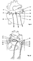
- Fig. 1 shows the back of the heart area with a fixation of the electrode assembly in the pericardium.
- the electrode arrangement (1) consists of two defibrillation electrodes (10) and (11).
- the indifferent poles (16) and (17) are pigtails.
- Defibrillation electrode (10) lies above the right atrium (2).
- Defibrillation electrode (11) lies above the left atrium (3).
- the pigtails are made of nitinol wire which has been waved by annealing. so that the pigtails each have an elasticity section (12) or (13).
- the wave consisting of wave crest and wave trough represents the elasticity section.
- Each pile wire terminates in an electrically insulated stainless steel stranded wire (14) or (15) which leads distally to the fixing element (20) or (21).
- the fixing element is an elastic T-bar, for example made of silicone, which is anchored in the pericardium (4).
- the pigtails (16) and (17) are reinforced by deferred spirals.
- Feed line (5a) is electrically conductively connected to the inside of the clamping sleeve (18).
- Feed line (5b) leads to the indifferent pile wire (10).
- Feed line (6a) is electrically conductively connected to the inside of the clamping sleeve (19).
- Feed line (6b) leads to the indifferent pile wire (11).
- Protective hoses (5) and (6) are guided together in the guide tube (7).
- the guide tube (7) is displaceable with respect to the longitudinal axis, so that the distance between the two defibrillation electrodes (10) and (11) and between the two different electrode poles (18) and (19) is variable. If the guide tube (7) is pushed upwards, the two clamping sleeves (18) and (19) approach each other. The shape and spacing of the defibrillation electrodes (10) and (11) also changes.
- Fig. 2 shows the in Fig. 1 illustrated electrode assembly.
- fixation element (20) or (21) can take different forms, such as zig-zag, anchor, loop and hook, nodes, multiple anchors, multiple nodes.
- the pole wire is pulled through the pericardium (4) until the fixation element has leaked out; If the fixation element is a multiple anchor until the desired anchor has emerged. By retracting the pole wire, the fixation element anchors in the pericardium.
- the electrode assembly has an additional bipolar stimulation electrode (30) whose leads are also passed through the guide tube (7).
- the stimulation electrode (30) allows further stimulation of the left atrium (3).
- Fig. 3 shows the in Fig. 1 shown electrode assembly wherein elasticity section (12) and (13) have a hexagonal shape.
- the pigtails of the indifferent poles are reinforced in the area of the hexagon by helices.
- the different electrode pole (18) or (19) lie within the hexagon.
- Fig. 4 shows the in Fig. 1 shown electrode assembly wherein elasticity section (12) and (13) have a circular shape.
- the pigtails of the indifferent poles are reinforced in the area of the circle by helices.
- the different electrode pole (18) or (19) lie within the circle.
- Fig. 5 shows the in Fig. 1 shown electrode assembly, which is characterized by a special arrangement of the elasticity section.
- the defibrillation electrodes (10) or (11) with the coils (16) or (17) slid on are connected by the elasticity section (100).
- the elasticity section consists for example of wavy molded insulated thread or stretchable silicone thread attached to both the defibrillation electrode (10) and the defibrillation electrode (11).
- Fig. 6 shows the in Fig. 1 illustrated electrode assembly, which is characterized by a special wave-shaped arrangement of the defibrillation electrode in protective tube form over the left and right atrium on the back of the heart.
- the two protective tube sections are shaped in such a way that the openings always point to the heart side during positioning of the electrode arrangement and, when a shock pulse is delivered, a flow of current into the pain-sensitive sides facing away from the heart is avoided.
- the openings of the wave-shaped protective tube section (52) over the left atrium fulfill the same purpose.
- Figure 7 shows another exemplary electrode assembly with wavy elastic section and a defibrillation electrode in protective tube form over the left and right atrium on the back of the heart.
- the protective tube sections (53), (54) are shaped to prevent inadvertent rotation of the openings during positioning.
- FIG. 12 shows another exemplary undulated elastic section electrode assembly in which only the left atrium (3) can be cardioverted / paced.
- the right atrium can be cardioverted / stimulated by a separate electrode arrangement on the back of the heart but also on the front of the heart.
- the elastic protective tube-shaped electrode assembly over the left atrium has two separate indifferent poles and a different pole (55). Between the different pole (56) and the indifferent poles, the left atrium can be stimulated and cardioverted between the two indifferent poles.
- the necessary shock energy for cardioversion can be reduced to a minimum, which is beneficial for the patient with regard to the sensation of pain
- Fig. 9 shows the front of the heart.
- the defibrillation electrodes (10) and (11) carry the fixing elements (20) and (21), which consist of two interlocking plates (57), which are put together and held together by means of a thread (58). After use, the thread can be pulled and the fixation elements separate so that the electrode assembly can also be removed from the back of the heart through the anterior orifice.
- the defibrillation electrodes (10) and (11) are undulating over the anterior heart area to the interlocking plates continued.
- additional separate bipolar electrodes (59), (60) are attached, which serve to stimulate the right and left ventricles.
- Fig. 10 shows a further embodiment of the inventive electrode assembly, wherein the elasticity sections have a hexagonal shape (61), (62).
- the hexagonal indifferent electrode (62) covering the entire left atrium is fixed separately on both sides of the pericardium (20), (21).
- the hexagonal indifferent electrode (61) placed over the right atrium is placed on one side of the pericardium so that the placement will accommodate the particular anatomical shape of the right atrium.
- the stimulation takes place in each case between the different poles (63), (64) within the hexagon and the elongated outer portions (65), (66) of the hexagon.
- Cardioversion occurs separately in the left and right atria. In the left atrium, cardioversion occurs between the electrically separate pole legs of the upper (67) and lower (66) portions of the hexagon. In the right atrium, the cardioversion occurs between the electrically separate poles of the right (65) and the left (68) pole of the hexagon.
Claims (10)
- Ensemble d'électrodes (1) pour la cardioversion temporaire et / ou pour la stimulation temporaire du coeur après une opération à coeur ouvert, comprenant:a) une première électrode de défibrillation (11) avec au moins un pôle indifférent (17) et une partie élastique (13), l'électrode de défibrillation (11) se trouve dans la position d'utilisation au-dessus de l'oreillette gauche (3), l'électrode de défibrillation comprend une élément de fixation (21) à l'extrémité distale et s'étend à l'extrémité proximale dans un tuyau de protection (6);b) une deuxième électrode de défibrillation (10) avec au moins un pôle indifférent (16) et une partie élastique (12), l'électrode de défibrillation (10) se trouve dans la position d'utilisation au-dessus de l'oreillette droite (2), l'électrode de défibrillation comprend une élément de fixation (20) à l'extrémité distale et s'étend à l'extrémité proximale dans un tuyau de protection (5);c) des pôles differents (18), (19);dans la position d'utilisation les éléments de fixation (20) et (21) peuvent être fixés dans le péricarde (4) sur le côté droit ou sur le côté gauche ou peuvent être ancrés les uns aux autres à l'avant du coeur,
les conduits électriques aux pôles passent à l'intérieur des tuyaux de protection (5) et (6) lesquelles s' etendent à travers un tube de guidage (7); le tube de guidage peut être déplacé par rapport à son axe longitudinal. - Ensemble d'électrodes selon la revendication 1, dans lequel les pôles indifférents (16) et (17) sont formés à partir d'un fil.
- Ensemble d'électrodes selon la revendication 2 , dans lequel les pôles sont formés à partir des fils de nitinol.
- Ensemble d'électrodes selon la revendication 2 ou 3, dans lequel les fils sont renforcés par au moins une hélice.
- Ensemble d'électrodes selon 1, dans lequel les pôles indifférents (16) et (17) sont formés à partir du fil torsadé.
- Ensemble d'électrodes selon l'une quelconque des revendications 1-5, dans lequel la surface des pôles métalliques (16) et (17) est revêtue d'une couche de platine ou d'or.
- Ensemble d'électrodes selon la revendication 1, dans lequel l'électrode de défibrillation est formé d'un tube avec au moins une lumière destinée à recevoir l'électrode et ayant une pluralité d'ouvertures pour le pôle indifférent et une ouverture pour l'autre pôle.
- Ensemble d'électrodes selon l'une quelconque des revendications 1-7, dans lequel les pôles différents (18), (18) sont réalisés sous la forme d'une douille de serrage.
- Ensemble d'électrodes selon l'une quelconque des revendications 1-8, dans lequel la partie élastique est de forme ondulée, de forme circulaire, de forme elliptique, ou de forme d'un polygone (hexagone).
- Ensemble d'électrodes selon l'une quelconque des revendications 1-9, dans lequel l'élément de fixation est un élément de zig-zag, une ancre, un oeillet, une boucle, une hélice, un élément en forme de V, une barre en T élastique ou un noeud.
Priority Applications (2)
| Application Number | Priority Date | Filing Date | Title |
|---|---|---|---|
| EP13004327.6A EP2845622B1 (fr) | 2013-09-04 | 2013-09-04 | Agencement d'électrodes pouvant être implanté temporairement pour la stimulation et la cardioversion intracardiaque du coeur après une opération |
| US14/465,253 US9463316B2 (en) | 2013-09-04 | 2014-08-21 | Temporarily implantable electrode assembly for the stimulation and intracardiac cardioversion/defibrillation of the heart following surgery |
Applications Claiming Priority (1)
| Application Number | Priority Date | Filing Date | Title |
|---|---|---|---|
| EP13004327.6A EP2845622B1 (fr) | 2013-09-04 | 2013-09-04 | Agencement d'électrodes pouvant être implanté temporairement pour la stimulation et la cardioversion intracardiaque du coeur après une opération |
Publications (2)
| Publication Number | Publication Date |
|---|---|
| EP2845622A1 EP2845622A1 (fr) | 2015-03-11 |
| EP2845622B1 true EP2845622B1 (fr) | 2018-02-21 |
Family
ID=49123633
Family Applications (1)
| Application Number | Title | Priority Date | Filing Date |
|---|---|---|---|
| EP13004327.6A Not-in-force EP2845622B1 (fr) | 2013-09-04 | 2013-09-04 | Agencement d'électrodes pouvant être implanté temporairement pour la stimulation et la cardioversion intracardiaque du coeur après une opération |
Country Status (2)
| Country | Link |
|---|---|
| US (1) | US9463316B2 (fr) |
| EP (1) | EP2845622B1 (fr) |
Families Citing this family (4)
| Publication number | Priority date | Publication date | Assignee | Title |
|---|---|---|---|---|
| AU2017376132A1 (en) | 2016-12-12 | 2019-07-11 | Neuronoff, Inc. | Electrode curable and moldable to contours of a target in bodily tissue and methods of manufacturing and placement and dispensers therefor |
| WO2018227019A1 (fr) * | 2017-06-07 | 2018-12-13 | Neuronexus Technologies, Inc. | Systèmes et procédés pour réseaux d'électrodes flexibles |
| US20200188660A1 (en) * | 2017-06-08 | 2020-06-18 | Neuronoff, Inc. | Electrode cured and manufactured in the body, and related methods and devices |
| US10835741B2 (en) * | 2018-03-27 | 2020-11-17 | Pacesetter, Inc. | Screw-in pericardial leads and systems for delivering screw-in pericardial leads |
Family Cites Families (13)
| Publication number | Priority date | Publication date | Assignee | Title |
|---|---|---|---|---|
| US4030509A (en) * | 1975-09-30 | 1977-06-21 | Mieczyslaw Mirowski | Implantable electrodes for accomplishing ventricular defibrillation and pacing and method of electrode implantation and utilization |
| DE3412950A1 (de) * | 1984-04-06 | 1985-10-17 | Peter Dr.-Ing. 7889 Grenzach-Wyhlen Osypka | Chirurgische elektrode |
| US5562708A (en) * | 1994-04-21 | 1996-10-08 | Medtronic, Inc. | Method and apparatus for treatment of atrial fibrillation |
| US6324435B1 (en) * | 2000-06-22 | 2001-11-27 | Ethicon, Inc. | Electrical connector for cardiac devices |
| EP1558332A2 (fr) * | 2002-11-07 | 2005-08-03 | Axiom Medical Inc. | Sonde cardiaque epicardique, drain thoracique avec sonde cardiaque epicardique et procede d'utilisation |
| US20070106359A1 (en) * | 2003-11-07 | 2007-05-10 | Alan Schaer | Cardiac harness assembly for treating congestive heart failure and for pacing/sensing |
| EP1898999A4 (fr) * | 2005-07-01 | 2011-10-19 | Proteus Biomedical Inc | Ensemble d'electrodes et de capteurs epicardique deployable |
| US8918193B2 (en) * | 2006-08-16 | 2014-12-23 | Vahe S. Yacoubian | Heart wire |
| JP2010029564A (ja) * | 2008-07-30 | 2010-02-12 | Olympus Corp | 除細動電極、除細動装置および内視鏡装置 |
| US20100312296A1 (en) * | 2008-12-23 | 2010-12-09 | Gray Richard J | Cardioversion electrode |
| DE202010011244U1 (de) | 2010-08-10 | 2010-11-04 | Osypka, Peter, Dr.-Ing. | Kardioverter zur Beseitigung von Vorhofflimmern |
| DE202010016681U1 (de) * | 2010-12-16 | 2011-05-05 | Osypka, Peter, Dr.-Ing. | Implantierbare Myokardiale Elektroden |
| DE102011111649A1 (de) | 2011-08-26 | 2013-02-28 | Peter Osypka | Implantierbare Epikardiale Elektroden Anordnung |
-
2013
- 2013-09-04 EP EP13004327.6A patent/EP2845622B1/fr not_active Not-in-force
-
2014
- 2014-08-21 US US14/465,253 patent/US9463316B2/en active Active
Non-Patent Citations (1)
| Title |
|---|
| None * |
Also Published As
| Publication number | Publication date |
|---|---|
| US9463316B2 (en) | 2016-10-11 |
| EP2845622A1 (fr) | 2015-03-11 |
| US20150066125A1 (en) | 2015-03-05 |
Similar Documents
| Publication | Publication Date | Title |
|---|---|---|
| EP0159540B1 (fr) | Electrode chirurgicale | |
| EP1038547B1 (fr) | Electrode cardiaque extensible destinée à être implantée dans le sinus coronaire | |
| DE3912377C2 (de) | Spiralförmige Fleckenelektrode für einen Herzdefibrillator bzw. Kardiovertierer | |
| DE69627290T2 (de) | Implantierbares Elektrodenkabel mit mindestens einem Elektrodenkontakt | |
| EP0211166B2 (fr) | Electrode de défibrillation | |
| EP2674189B1 (fr) | Pôle d'électrodes implantables | |
| EP2747835B1 (fr) | Ensemble d'électrodes épicardiales implantables | |
| EP0892653A1 (fr) | Systeme d'electrodes | |
| DE19654491A1 (de) | Stimulationselektrodenanordnung | |
| EP3328482B1 (fr) | Systeme d'electrode a courant continu implantable | |
| EP2845622B1 (fr) | Agencement d'électrodes pouvant être implanté temporairement pour la stimulation et la cardioversion intracardiaque du coeur après une opération | |
| EP0779079B1 (fr) | Sonde à électrode unique pour stimulateurs cardiaques double chambre, en particulier pour stimulateurs cardiaques de type DD | |
| EP2679275B1 (fr) | Électrode épicardique de cartographie | |
| EP2059296B1 (fr) | Dispositif de défibrillation du coeur | |
| DE102017008720A1 (de) | Temporär implantierbare myokardiale bipolare Elektrodenvorrichtung | |
| DE202010016681U1 (de) | Implantierbare Myokardiale Elektroden | |
| EP2785410A2 (fr) | Électrode inerte implantable | |
| EP2817063B1 (fr) | Électrode myocardique pour stimulateur cardiaque | |
| EP2143463A1 (fr) | Mesures améliorées de perte de chemin dans des communications sans fil | |
| EP2679276A1 (fr) | Bande de stimulation épicardique | |
| EP3725360A1 (fr) | Électrode myocardique bipolaire temporaire | |
| EP2809388A1 (fr) | Fixation d'électrodes myocardiques implantables | |
| EP0927561A2 (fr) | Système d'électrodes de défibrillation | |
| DE2932596C2 (de) | Implantierbare Elektrode | |
| DE202013011345U1 (de) | Implantierbare indifferente Elektrode |
Legal Events
| Date | Code | Title | Description |
|---|---|---|---|
| 17P | Request for examination filed |
Effective date: 20130904 |
|
| AK | Designated contracting states |
Kind code of ref document: A1 Designated state(s): AL AT BE BG CH CY CZ DE DK EE ES FI FR GB GR HR HU IE IS IT LI LT LU LV MC MK MT NL NO PL PT RO RS SE SI SK SM TR |
|
| AX | Request for extension of the european patent |
Extension state: BA ME |
|
| PUAI | Public reference made under article 153(3) epc to a published international application that has entered the european phase |
Free format text: ORIGINAL CODE: 0009012 |
|
| R17P | Request for examination filed (corrected) |
Effective date: 20150729 |
|
| RBV | Designated contracting states (corrected) |
Designated state(s): AL AT BE BG CH CY CZ DE DK EE ES FI FR GB GR HR HU IE IS IT LI LT LU LV MC MK MT NL NO PL PT RO RS SE SI SK SM TR |
|
| GRAP | Despatch of communication of intention to grant a patent |
Free format text: ORIGINAL CODE: EPIDOSNIGR1 |
|
| INTG | Intention to grant announced |
Effective date: 20171122 |
|
| GRAS | Grant fee paid |
Free format text: ORIGINAL CODE: EPIDOSNIGR3 |
|
| GRAA | (expected) grant |
Free format text: ORIGINAL CODE: 0009210 |
|
| AK | Designated contracting states |
Kind code of ref document: B1 Designated state(s): AL AT BE BG CH CY CZ DE DK EE ES FI FR GB GR HR HU IE IS IT LI LT LU LV MC MK MT NL NO PL PT RO RS SE SI SK SM TR |
|
| REG | Reference to a national code |
Ref country code: GB Ref legal event code: FG4D Free format text: NOT ENGLISH |
|
| REG | Reference to a national code |
Ref country code: CH Ref legal event code: EP |
|
| REG | Reference to a national code |
Ref country code: DE Ref legal event code: R096 Ref document number: 502013009429 Country of ref document: DE Ref country code: AT Ref legal event code: REF Ref document number: 971054 Country of ref document: AT Kind code of ref document: T Effective date: 20180315 |
|
| REG | Reference to a national code |
Ref country code: IE Ref legal event code: FG4D Free format text: LANGUAGE OF EP DOCUMENT: GERMAN |
|
| REG | Reference to a national code |
Ref country code: NL Ref legal event code: MP Effective date: 20180221 |
|
| REG | Reference to a national code |
Ref country code: LT Ref legal event code: MG4D |
|
| PG25 | Lapsed in a contracting state [announced via postgrant information from national office to epo] |
Ref country code: NL Free format text: LAPSE BECAUSE OF FAILURE TO SUBMIT A TRANSLATION OF THE DESCRIPTION OR TO PAY THE FEE WITHIN THE PRESCRIBED TIME-LIMIT Effective date: 20180221 Ref country code: CY Free format text: LAPSE BECAUSE OF FAILURE TO SUBMIT A TRANSLATION OF THE DESCRIPTION OR TO PAY THE FEE WITHIN THE PRESCRIBED TIME-LIMIT Effective date: 20180221 Ref country code: FI Free format text: LAPSE BECAUSE OF FAILURE TO SUBMIT A TRANSLATION OF THE DESCRIPTION OR TO PAY THE FEE WITHIN THE PRESCRIBED TIME-LIMIT Effective date: 20180221 Ref country code: NO Free format text: LAPSE BECAUSE OF FAILURE TO SUBMIT A TRANSLATION OF THE DESCRIPTION OR TO PAY THE FEE WITHIN THE PRESCRIBED TIME-LIMIT Effective date: 20180521 Ref country code: LT Free format text: LAPSE BECAUSE OF FAILURE TO SUBMIT A TRANSLATION OF THE DESCRIPTION OR TO PAY THE FEE WITHIN THE PRESCRIBED TIME-LIMIT Effective date: 20180221 Ref country code: HR Free format text: LAPSE BECAUSE OF FAILURE TO SUBMIT A TRANSLATION OF THE DESCRIPTION OR TO PAY THE FEE WITHIN THE PRESCRIBED TIME-LIMIT Effective date: 20180221 Ref country code: ES Free format text: LAPSE BECAUSE OF FAILURE TO SUBMIT A TRANSLATION OF THE DESCRIPTION OR TO PAY THE FEE WITHIN THE PRESCRIBED TIME-LIMIT Effective date: 20180221 |
|
| PG25 | Lapsed in a contracting state [announced via postgrant information from national office to epo] |
Ref country code: LV Free format text: LAPSE BECAUSE OF FAILURE TO SUBMIT A TRANSLATION OF THE DESCRIPTION OR TO PAY THE FEE WITHIN THE PRESCRIBED TIME-LIMIT Effective date: 20180221 Ref country code: SE Free format text: LAPSE BECAUSE OF FAILURE TO SUBMIT A TRANSLATION OF THE DESCRIPTION OR TO PAY THE FEE WITHIN THE PRESCRIBED TIME-LIMIT Effective date: 20180221 Ref country code: RS Free format text: LAPSE BECAUSE OF FAILURE TO SUBMIT A TRANSLATION OF THE DESCRIPTION OR TO PAY THE FEE WITHIN THE PRESCRIBED TIME-LIMIT Effective date: 20180221 Ref country code: BG Free format text: LAPSE BECAUSE OF FAILURE TO SUBMIT A TRANSLATION OF THE DESCRIPTION OR TO PAY THE FEE WITHIN THE PRESCRIBED TIME-LIMIT Effective date: 20180521 Ref country code: GR Free format text: LAPSE BECAUSE OF FAILURE TO SUBMIT A TRANSLATION OF THE DESCRIPTION OR TO PAY THE FEE WITHIN THE PRESCRIBED TIME-LIMIT Effective date: 20180522 |
|
| REG | Reference to a national code |
Ref country code: FR Ref legal event code: PLFP Year of fee payment: 6 |
|
| PG25 | Lapsed in a contracting state [announced via postgrant information from national office to epo] |
Ref country code: MT Free format text: LAPSE BECAUSE OF FAILURE TO SUBMIT A TRANSLATION OF THE DESCRIPTION OR TO PAY THE FEE WITHIN THE PRESCRIBED TIME-LIMIT Effective date: 20180221 |
|
| PG25 | Lapsed in a contracting state [announced via postgrant information from national office to epo] |
Ref country code: IT Free format text: LAPSE BECAUSE OF FAILURE TO SUBMIT A TRANSLATION OF THE DESCRIPTION OR TO PAY THE FEE WITHIN THE PRESCRIBED TIME-LIMIT Effective date: 20180221 Ref country code: RO Free format text: LAPSE BECAUSE OF FAILURE TO SUBMIT A TRANSLATION OF THE DESCRIPTION OR TO PAY THE FEE WITHIN THE PRESCRIBED TIME-LIMIT Effective date: 20180221 Ref country code: PL Free format text: LAPSE BECAUSE OF FAILURE TO SUBMIT A TRANSLATION OF THE DESCRIPTION OR TO PAY THE FEE WITHIN THE PRESCRIBED TIME-LIMIT Effective date: 20180221 Ref country code: EE Free format text: LAPSE BECAUSE OF FAILURE TO SUBMIT A TRANSLATION OF THE DESCRIPTION OR TO PAY THE FEE WITHIN THE PRESCRIBED TIME-LIMIT Effective date: 20180221 Ref country code: AL Free format text: LAPSE BECAUSE OF FAILURE TO SUBMIT A TRANSLATION OF THE DESCRIPTION OR TO PAY THE FEE WITHIN THE PRESCRIBED TIME-LIMIT Effective date: 20180221 |
|
| REG | Reference to a national code |
Ref country code: DE Ref legal event code: R097 Ref document number: 502013009429 Country of ref document: DE |
|
| PG25 | Lapsed in a contracting state [announced via postgrant information from national office to epo] |
Ref country code: DK Free format text: LAPSE BECAUSE OF FAILURE TO SUBMIT A TRANSLATION OF THE DESCRIPTION OR TO PAY THE FEE WITHIN THE PRESCRIBED TIME-LIMIT Effective date: 20180221 Ref country code: SM Free format text: LAPSE BECAUSE OF FAILURE TO SUBMIT A TRANSLATION OF THE DESCRIPTION OR TO PAY THE FEE WITHIN THE PRESCRIBED TIME-LIMIT Effective date: 20180221 Ref country code: SK Free format text: LAPSE BECAUSE OF FAILURE TO SUBMIT A TRANSLATION OF THE DESCRIPTION OR TO PAY THE FEE WITHIN THE PRESCRIBED TIME-LIMIT Effective date: 20180221 Ref country code: CZ Free format text: LAPSE BECAUSE OF FAILURE TO SUBMIT A TRANSLATION OF THE DESCRIPTION OR TO PAY THE FEE WITHIN THE PRESCRIBED TIME-LIMIT Effective date: 20180221 |
|
| PLBE | No opposition filed within time limit |
Free format text: ORIGINAL CODE: 0009261 |
|
| STAA | Information on the status of an ep patent application or granted ep patent |
Free format text: STATUS: NO OPPOSITION FILED WITHIN TIME LIMIT |
|
| 26N | No opposition filed |
Effective date: 20181122 |
|
| PG25 | Lapsed in a contracting state [announced via postgrant information from national office to epo] |
Ref country code: SI Free format text: LAPSE BECAUSE OF FAILURE TO SUBMIT A TRANSLATION OF THE DESCRIPTION OR TO PAY THE FEE WITHIN THE PRESCRIBED TIME-LIMIT Effective date: 20180221 |
|
| PG25 | Lapsed in a contracting state [announced via postgrant information from national office to epo] |
Ref country code: MC Free format text: LAPSE BECAUSE OF FAILURE TO SUBMIT A TRANSLATION OF THE DESCRIPTION OR TO PAY THE FEE WITHIN THE PRESCRIBED TIME-LIMIT Effective date: 20180221 |
|
| REG | Reference to a national code |
Ref country code: CH Ref legal event code: PL |
|
| REG | Reference to a national code |
Ref country code: BE Ref legal event code: MM Effective date: 20180930 |
|
| REG | Reference to a national code |
Ref country code: IE Ref legal event code: MM4A |
|
| PG25 | Lapsed in a contracting state [announced via postgrant information from national office to epo] |
Ref country code: LU Free format text: LAPSE BECAUSE OF NON-PAYMENT OF DUE FEES Effective date: 20180904 |
|
| PG25 | Lapsed in a contracting state [announced via postgrant information from national office to epo] |
Ref country code: IE Free format text: LAPSE BECAUSE OF NON-PAYMENT OF DUE FEES Effective date: 20180904 |
|
| PG25 | Lapsed in a contracting state [announced via postgrant information from national office to epo] |
Ref country code: CH Free format text: LAPSE BECAUSE OF NON-PAYMENT OF DUE FEES Effective date: 20180930 Ref country code: LI Free format text: LAPSE BECAUSE OF NON-PAYMENT OF DUE FEES Effective date: 20180930 Ref country code: BE Free format text: LAPSE BECAUSE OF NON-PAYMENT OF DUE FEES Effective date: 20180930 |
|
| PGFP | Annual fee paid to national office [announced via postgrant information from national office to epo] |
Ref country code: DE Payment date: 20190814 Year of fee payment: 7 Ref country code: FR Payment date: 20190902 Year of fee payment: 7 |
|
| REG | Reference to a national code |
Ref country code: AT Ref legal event code: MM01 Ref document number: 971054 Country of ref document: AT Kind code of ref document: T Effective date: 20180904 |
|
| PGFP | Annual fee paid to national office [announced via postgrant information from national office to epo] |
Ref country code: GB Payment date: 20190815 Year of fee payment: 7 |
|
| PG25 | Lapsed in a contracting state [announced via postgrant information from national office to epo] |
Ref country code: AT Free format text: LAPSE BECAUSE OF NON-PAYMENT OF DUE FEES Effective date: 20180904 |
|
| PG25 | Lapsed in a contracting state [announced via postgrant information from national office to epo] |
Ref country code: TR Free format text: LAPSE BECAUSE OF FAILURE TO SUBMIT A TRANSLATION OF THE DESCRIPTION OR TO PAY THE FEE WITHIN THE PRESCRIBED TIME-LIMIT Effective date: 20180221 |
|
| PG25 | Lapsed in a contracting state [announced via postgrant information from national office to epo] |
Ref country code: HU Free format text: LAPSE BECAUSE OF FAILURE TO SUBMIT A TRANSLATION OF THE DESCRIPTION OR TO PAY THE FEE WITHIN THE PRESCRIBED TIME-LIMIT; INVALID AB INITIO Effective date: 20130904 Ref country code: PT Free format text: LAPSE BECAUSE OF FAILURE TO SUBMIT A TRANSLATION OF THE DESCRIPTION OR TO PAY THE FEE WITHIN THE PRESCRIBED TIME-LIMIT Effective date: 20180221 |
|
| PG25 | Lapsed in a contracting state [announced via postgrant information from national office to epo] |
Ref country code: MK Free format text: LAPSE BECAUSE OF NON-PAYMENT OF DUE FEES Effective date: 20180221 |
|
| PG25 | Lapsed in a contracting state [announced via postgrant information from national office to epo] |
Ref country code: IS Free format text: LAPSE BECAUSE OF FAILURE TO SUBMIT A TRANSLATION OF THE DESCRIPTION OR TO PAY THE FEE WITHIN THE PRESCRIBED TIME-LIMIT Effective date: 20180621 |
|
| REG | Reference to a national code |
Ref country code: DE Ref legal event code: R119 Ref document number: 502013009429 Country of ref document: DE |
|
| GBPC | Gb: european patent ceased through non-payment of renewal fee |
Effective date: 20200904 |
|
| PG25 | Lapsed in a contracting state [announced via postgrant information from national office to epo] |
Ref country code: DE Free format text: LAPSE BECAUSE OF NON-PAYMENT OF DUE FEES Effective date: 20210401 Ref country code: FR Free format text: LAPSE BECAUSE OF NON-PAYMENT OF DUE FEES Effective date: 20200930 |
|
| PG25 | Lapsed in a contracting state [announced via postgrant information from national office to epo] |
Ref country code: GB Free format text: LAPSE BECAUSE OF NON-PAYMENT OF DUE FEES Effective date: 20200904 |