EP2845622B1 - Temporarily implantable electrode assembly for stimulation and intracardial cardioversion of the heart after surgery - Google Patents
Temporarily implantable electrode assembly for stimulation and intracardial cardioversion of the heart after surgery Download PDFInfo
- Publication number
- EP2845622B1 EP2845622B1 EP13004327.6A EP13004327A EP2845622B1 EP 2845622 B1 EP2845622 B1 EP 2845622B1 EP 13004327 A EP13004327 A EP 13004327A EP 2845622 B1 EP2845622 B1 EP 2845622B1
- Authority
- EP
- European Patent Office
- Prior art keywords
- electrode
- electrode assembly
- heart
- assembly according
- pole
- Prior art date
- Legal status (The legal status is an assumption and is not a legal conclusion. Google has not performed a legal analysis and makes no representation as to the accuracy of the status listed.)
- Not-in-force
Links
Images


Classifications
-
- A—HUMAN NECESSITIES
- A61—MEDICAL OR VETERINARY SCIENCE; HYGIENE
- A61N—ELECTROTHERAPY; MAGNETOTHERAPY; RADIATION THERAPY; ULTRASOUND THERAPY
- A61N1/00—Electrotherapy; Circuits therefor
- A61N1/02—Details
- A61N1/04—Electrodes
- A61N1/0404—Electrodes for external use
- A61N1/0472—Structure-related aspects
- A61N1/0492—Patch electrodes
-
- A—HUMAN NECESSITIES
- A61—MEDICAL OR VETERINARY SCIENCE; HYGIENE
- A61N—ELECTROTHERAPY; MAGNETOTHERAPY; RADIATION THERAPY; ULTRASOUND THERAPY
- A61N1/00—Electrotherapy; Circuits therefor
- A61N1/02—Details
- A61N1/04—Electrodes
- A61N1/05—Electrodes for implantation or insertion into the body, e.g. heart electrode
- A61N1/0587—Epicardial electrode systems; Endocardial electrodes piercing the pericardium
- A61N1/059—Anchoring means
-
- A—HUMAN NECESSITIES
- A61—MEDICAL OR VETERINARY SCIENCE; HYGIENE
- A61N—ELECTROTHERAPY; MAGNETOTHERAPY; RADIATION THERAPY; ULTRASOUND THERAPY
- A61N1/00—Electrotherapy; Circuits therefor
- A61N1/02—Details
- A61N1/04—Electrodes
- A61N1/05—Electrodes for implantation or insertion into the body, e.g. heart electrode
- A61N1/0587—Epicardial electrode systems; Endocardial electrodes piercing the pericardium
- A61N1/0597—Surface area electrodes, e.g. cardiac harness
-
- A—HUMAN NECESSITIES
- A61—MEDICAL OR VETERINARY SCIENCE; HYGIENE
- A61N—ELECTROTHERAPY; MAGNETOTHERAPY; RADIATION THERAPY; ULTRASOUND THERAPY
- A61N1/00—Electrotherapy; Circuits therefor
- A61N1/18—Applying electric currents by contact electrodes
- A61N1/32—Applying electric currents by contact electrodes alternating or intermittent currents
- A61N1/38—Applying electric currents by contact electrodes alternating or intermittent currents for producing shock effects
- A61N1/39—Heart defibrillators
- A61N1/3968—Constructional arrangements, e.g. casings
-
- A—HUMAN NECESSITIES
- A61—MEDICAL OR VETERINARY SCIENCE; HYGIENE
- A61N—ELECTROTHERAPY; MAGNETOTHERAPY; RADIATION THERAPY; ULTRASOUND THERAPY
- A61N1/00—Electrotherapy; Circuits therefor
- A61N1/18—Applying electric currents by contact electrodes
- A61N1/32—Applying electric currents by contact electrodes alternating or intermittent currents
- A61N1/36—Applying electric currents by contact electrodes alternating or intermittent currents for stimulation
- A61N1/362—Heart stimulators
- A61N1/365—Heart stimulators controlled by a physiological parameter, e.g. heart potential
- A61N1/368—Heart stimulators controlled by a physiological parameter, e.g. heart potential comprising more than one electrode co-operating with different heart regions
- A61N1/3684—Heart stimulators controlled by a physiological parameter, e.g. heart potential comprising more than one electrode co-operating with different heart regions for stimulating the heart at multiple sites of the ventricle or the atrium
- A61N1/36842—Multi-site stimulation in the same chamber
-
- A—HUMAN NECESSITIES
- A61—MEDICAL OR VETERINARY SCIENCE; HYGIENE
- A61N—ELECTROTHERAPY; MAGNETOTHERAPY; RADIATION THERAPY; ULTRASOUND THERAPY
- A61N1/00—Electrotherapy; Circuits therefor
- A61N1/18—Applying electric currents by contact electrodes
- A61N1/32—Applying electric currents by contact electrodes alternating or intermittent currents
- A61N1/36—Applying electric currents by contact electrodes alternating or intermittent currents for stimulation
- A61N1/362—Heart stimulators
- A61N1/365—Heart stimulators controlled by a physiological parameter, e.g. heart potential
- A61N1/368—Heart stimulators controlled by a physiological parameter, e.g. heart potential comprising more than one electrode co-operating with different heart regions
- A61N1/3684—Heart stimulators controlled by a physiological parameter, e.g. heart potential comprising more than one electrode co-operating with different heart regions for stimulating the heart at multiple sites of the ventricle or the atrium
- A61N1/36843—Bi-ventricular stimulation
Definitions
- the invention relates to a temporary implantable elastic electrode assembly with fixation elements for the monitoring and / or stimulation of the heart and / or cardioversion in atrial fibrillation after cardiac surgery. Due to its elasticity, the electrode arrangement is easy to position and fix on the back of the heart without injuring the epicardium. After use, the electrode assembly is easily removable again.
- Temporary myocardial electrodes also known as heart wires
- Such electrodes have been known for many years and are routinely used to stimulate the atria and ventricles after any open heart surgery.
- the fixation and thus the stimulation of the atria of the heart in particular the stimulation of the left atrium with heart wires, prepares considerable difficulties because of the special anatomical position of the left atrium.
- the purpose of the electrode arrangement is to allow the atria of the heart to be separated or jointly stimulated or cardioverted (defibrillated) more easily and more quickly. After completion of the therapy, the electrode assembly must again be easy to remove without mechanical impairment (friction) of the epicardium.
- the object is achieved by an electrode arrangement, which allows for a specifically tuned combination of an elastic defibrillation electrode with an elastic fixation element for reversible fixation of the defibrillation electrode, the inevitable for the therapy inevitable physically stable position of the electrodes around the left atrium / atria.
- the invention thus relates to an electrode arrangement (1) according to claim 1.
- the electrode arrangement makes it possible both to stimulate and to cardiovert between the pole pairs (16), (18) and (17), (19). There is also the possibility of cardioverting the atria of the heart simultaneously between the indifferent poles (16), (17).
- the protective tubes (5), (6) protect the epicardium. In the protective tubes (5), (6) extend the electrical leads to the poles of the electrodes. The leads are suitably a flexible wire.
- additional stimulation electrodes may be present to stimulate the left and / or right atria as well as to stimulate the ventricles.
- An additional bipolar stimulation electrode for stimulation of the left atrium is in Fig. 2 shown.
- the electrical supply line for the stimulation electrode is expediently guided through the guide tube (7).
- Fig. 9 shows stimulation electrodes for the ventricles. In a preferred embodiment, the guide tube is present. (Claim 2)
- the guide tube has the advantage that after the fixation of the defibrillation electrodes by simply moving the guide tube, a readjustment of the position of the electrode poles is possible.
- the guide tube is made of plastic, for example polyethylene. It forms a channel for the protective tubes (5) and (6) and is displaceable in its longitudinal direction. At the upper end of the guide tube, the protective tubes (5) and (6) emerge. The electrode poles are connected to the electrical leads that run in the protective tubes. At the bottom of the protective tubes are passed through an opening in the chest to the outside and the electrical leads connected to a pacemaker or defibrillator.
- each electrode arrangement can be easily adapted to the anatomical conditions of the respective heart.
- the defibrillation electrode is connected proximally to the electrical lead and carries distally the fixation element.
- the defibrillation electrode is an insulated strand and a pigtail.
- the pole wire is the indifferent electrode pole.
- the pole wire is made of a conductive metallic material, preferably of a shape memory material such as Nitinol.
- the pile wire can be reinforced by sliding on at least one coil.
- (Claim 5) It can also be postponed several coils.
- the reversible is made of an electrically conductive material, preferably platinum or stainless steel and reinforces the pole wire, thus improving the contact with the heart surface.
- the different electrode pole can be mounted on the defibrillation electrode.
- the different electrode pole is formed, for example, as an insulated relative to the Poldraht clamping sleeve which sits on the Poldraht or also consists of a portion of the Poldrahts. (Claim 9)
- the pile wire can be isolated on the side facing away from the heart by a coating with plastic. This measure avoids a flow of current into the pain-sensitive sides facing away from the heart.
- the defibrillation pole can also consist of a stainless steel strand. (Claim 6)
- the different electrode pole is formed for example as a clamping sleeve which sits on the strand or also consists of a portion of the strand.
- the strand can be isolated on the side facing away from the heart by a coating with plastic.
- the surface of the metallic poles is coated with a layer of platinum or gold. (Claim 7)
- the coating of the electrode poles with a noble metal layer is particularly important to prevent the formation of an oxide layer in a series of cardioversion.
- the defibrillation electrode is formed in a tubular shape.
- the hose is made of a flexible material. Suitable material is for example silicone, Dacron, polyurethane, polyester, silk or polyimide.
- the tube has at least one lumen for receiving the electrodes. On the side facing the heart, the tube has several openings for the indifferent pole and an opening for the different pole, which allows electrical current flow during stimulation / cardioversion. This measure avoids a flow of current into the pain-sensitive sides facing away from the heart.
- the two poles consist of a helix of, for example, six insulated wires made of stainless steel, which is integrated in the tube with corresponding openings.
- a low-impedance lead for example, a lead made of silver or a precious metal, which is electrically connected distally to the helix.
- the insulation of four spiral wires is removed so that, if necessary, an electric current can flow through the wires arranged in parallel.
- the two remaining two insulated wires of the coil form proximally, after removal of the insulation at the opening provided, the different electrode pole.
- Elasticity section refers to an area on the defibrillation electrode that can be pulled apart and that contracts again after the defibrillation electrode has been fixed. This can be achieved, for example, by shaping the defibrillation electrode into waveform, circular shape, ellipse shape, polygon (hexagon) or any other shape that can be pulled apart. Particularly suitable material for shaping is shape memory material such as Nitinol. In the above example, the wave, the circle, the ellipse, the hexagon is the elastic section.
- the defibrillation electrode or parts thereof consists of a stretchable plastic such as silicone on which the electrode poles are attached.
- the elastic portion allows the defibrillation electrode to be pulled apart around the atria on the posterior side of the heart as the electrode assembly is placed, facilitating push-up of the electrode assembly under the heart.
- the elastic portion allows at the same time that the fixing elements can be pulled through the pericardium. After the fixation elements are positioned, the defibrillation electrode resumes its original shape and thus ensures optimal stable contact of the electrode poles on the heart surface. When the defibrillation electrode is pulled back into its original shape, anchoring in the pericardium is achieved at the same time.
- the elastic portion allows flexibility in construction, and particularly in the shape that allows by-passes or other wounds resulting from the operation to be bypassed.
- the defibrillation electrode carries a fixation element at the distal end facing the pericardium.
- the fixing element has to fulfill two functions. On the one hand, there must be a stable anchoring during the duration of treatment, on the other hand, the anchorage after treatment must also be easily resolved, so that a later removal by a small opening with otherwise closed thorax is possible.
- fixation elements for fixation in the pericardium are all known from the prior art elements such as Zig-Zag, anchor, eyelets, loop, helix, V-shape, elastic T-bar, knot.
- the fixing elements (20) and (21) may be the same or different. In a preferred embodiment, they are the same, that is both fixation element (20) and fixing element (21) are, for example, an anchor.
- the fixation element is pulled through the pericardium, for example with a heart needle. After fixation, the needle is cut off. The positioning and fixation can also be done with the help of an introducer.
- the fixation elements e.g., anchor or zig-zag
- the fixation element is a number of anchors.
- the anchoring is achieved by splicing the anchor.
- the heart needle is used to pull the defibrillation electrode through the pericardium until the desired anchor has emerged.
- the armature splices. The rest is cut off.
- the fixation is provided on the front side of the heart.
- the two defibrillation electrodes are pulled around the atria of the heart and the two fixation elements are temporarily connected to each other at the front side of the heart.
- the fixing elements suitably consist of two interlocking plates, which are put together and held together by means of a thread.
- the thread is guided as the electrical leads of the electrode assembly through a small body opening to the outside. After use, the thread can be pulled and the fixation elements separate so that the electrode assembly can also be removed from the back of the heart through the anterior orifice.
- the sections in the front heart area are insulated and are also formed in shaft sections.
- the resilient properties of the defibrillation electrode provide a tight fit of the electrode assembly to the heart.
- the inventive electrode arrangement not only allows the optimal cardioversion and stimulation of the atria of the heart, but also a simultaneous stimulation of the ventricles.
- bipolar stimulation outlets are attached at a suitable point of the electrode arrangement in the anterior or posterior region of the heart.
- the great advantage of the electrode arrangement according to the invention is that the construction of the electrode arrangement makes it possible for the surgeon first to position the defibrillation electrodes on the left and right atria, fix them and, if necessary, readjust them after fixation by simply displacing the guide tube. This ensures that the electrode contact with the heart surface is excellent without the epicardium being damaged.
- the electrode contact is optimized so that the defibrillation with extremely low shock energy can be made.
- An extremely low shock energy is in the range of 0.1 Joule and less.
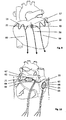
- Fig. 1 shows the back of the heart area with a fixation of the electrode assembly in the pericardium.
- the electrode arrangement (1) consists of two defibrillation electrodes (10) and (11).
- the indifferent poles (16) and (17) are pigtails.
- Defibrillation electrode (10) lies above the right atrium (2).
- Defibrillation electrode (11) lies above the left atrium (3).
- the pigtails are made of nitinol wire which has been waved by annealing. so that the pigtails each have an elasticity section (12) or (13).
- the wave consisting of wave crest and wave trough represents the elasticity section.
- Each pile wire terminates in an electrically insulated stainless steel stranded wire (14) or (15) which leads distally to the fixing element (20) or (21).
- the fixing element is an elastic T-bar, for example made of silicone, which is anchored in the pericardium (4).
- the pigtails (16) and (17) are reinforced by deferred spirals.
- Feed line (5a) is electrically conductively connected to the inside of the clamping sleeve (18).
- Feed line (5b) leads to the indifferent pile wire (10).
- Feed line (6a) is electrically conductively connected to the inside of the clamping sleeve (19).
- Feed line (6b) leads to the indifferent pile wire (11).
- Protective hoses (5) and (6) are guided together in the guide tube (7).
- the guide tube (7) is displaceable with respect to the longitudinal axis, so that the distance between the two defibrillation electrodes (10) and (11) and between the two different electrode poles (18) and (19) is variable. If the guide tube (7) is pushed upwards, the two clamping sleeves (18) and (19) approach each other. The shape and spacing of the defibrillation electrodes (10) and (11) also changes.
- Fig. 2 shows the in Fig. 1 illustrated electrode assembly.
- fixation element (20) or (21) can take different forms, such as zig-zag, anchor, loop and hook, nodes, multiple anchors, multiple nodes.
- the pole wire is pulled through the pericardium (4) until the fixation element has leaked out; If the fixation element is a multiple anchor until the desired anchor has emerged. By retracting the pole wire, the fixation element anchors in the pericardium.
- the electrode assembly has an additional bipolar stimulation electrode (30) whose leads are also passed through the guide tube (7).
- the stimulation electrode (30) allows further stimulation of the left atrium (3).
- Fig. 3 shows the in Fig. 1 shown electrode assembly wherein elasticity section (12) and (13) have a hexagonal shape.
- the pigtails of the indifferent poles are reinforced in the area of the hexagon by helices.
- the different electrode pole (18) or (19) lie within the hexagon.
- Fig. 4 shows the in Fig. 1 shown electrode assembly wherein elasticity section (12) and (13) have a circular shape.
- the pigtails of the indifferent poles are reinforced in the area of the circle by helices.
- the different electrode pole (18) or (19) lie within the circle.
- Fig. 5 shows the in Fig. 1 shown electrode assembly, which is characterized by a special arrangement of the elasticity section.
- the defibrillation electrodes (10) or (11) with the coils (16) or (17) slid on are connected by the elasticity section (100).
- the elasticity section consists for example of wavy molded insulated thread or stretchable silicone thread attached to both the defibrillation electrode (10) and the defibrillation electrode (11).
- Fig. 6 shows the in Fig. 1 illustrated electrode assembly, which is characterized by a special wave-shaped arrangement of the defibrillation electrode in protective tube form over the left and right atrium on the back of the heart.
- the two protective tube sections are shaped in such a way that the openings always point to the heart side during positioning of the electrode arrangement and, when a shock pulse is delivered, a flow of current into the pain-sensitive sides facing away from the heart is avoided.
- the openings of the wave-shaped protective tube section (52) over the left atrium fulfill the same purpose.
- Figure 7 shows another exemplary electrode assembly with wavy elastic section and a defibrillation electrode in protective tube form over the left and right atrium on the back of the heart.
- the protective tube sections (53), (54) are shaped to prevent inadvertent rotation of the openings during positioning.
- FIG. 12 shows another exemplary undulated elastic section electrode assembly in which only the left atrium (3) can be cardioverted / paced.
- the right atrium can be cardioverted / stimulated by a separate electrode arrangement on the back of the heart but also on the front of the heart.
- the elastic protective tube-shaped electrode assembly over the left atrium has two separate indifferent poles and a different pole (55). Between the different pole (56) and the indifferent poles, the left atrium can be stimulated and cardioverted between the two indifferent poles.
- the necessary shock energy for cardioversion can be reduced to a minimum, which is beneficial for the patient with regard to the sensation of pain
- Fig. 9 shows the front of the heart.
- the defibrillation electrodes (10) and (11) carry the fixing elements (20) and (21), which consist of two interlocking plates (57), which are put together and held together by means of a thread (58). After use, the thread can be pulled and the fixation elements separate so that the electrode assembly can also be removed from the back of the heart through the anterior orifice.
- the defibrillation electrodes (10) and (11) are undulating over the anterior heart area to the interlocking plates continued.
- additional separate bipolar electrodes (59), (60) are attached, which serve to stimulate the right and left ventricles.
- Fig. 10 shows a further embodiment of the inventive electrode assembly, wherein the elasticity sections have a hexagonal shape (61), (62).
- the hexagonal indifferent electrode (62) covering the entire left atrium is fixed separately on both sides of the pericardium (20), (21).
- the hexagonal indifferent electrode (61) placed over the right atrium is placed on one side of the pericardium so that the placement will accommodate the particular anatomical shape of the right atrium.
- the stimulation takes place in each case between the different poles (63), (64) within the hexagon and the elongated outer portions (65), (66) of the hexagon.
- Cardioversion occurs separately in the left and right atria. In the left atrium, cardioversion occurs between the electrically separate pole legs of the upper (67) and lower (66) portions of the hexagon. In the right atrium, the cardioversion occurs between the electrically separate poles of the right (65) and the left (68) pole of the hexagon.
Description
Die Erfindung betrifft eine temporär implantierbare elastische Elektrodenanordnung mit Fixierungselementen für die Überwachung und / oder Stimulation des Herzens und / oder zur Kardioversion bei Vorhofflimmem nach einer Herzoperation. Die Elektrodenanordnung ist aufgrund ihrer Elastizität leicht auf der Rückseite des Herzens zu positionieren und zu fixieren ohne dass das Epikard verletzt wird. Nach der Anwendung ist die Elektrodenanordnung wieder leicht entfernbar.
Temporäre Myokardiale Elektroden (auch als Herzdrähte bekannt) ermöglichen nach einer Herzoperation eine externe Stimulation des Herzens. Derartige Elektroden sind seit vielen Jahren bekannt und werden routinemäßig nach jeder offenen Herzoperation zur Stimulation der Vorhöfe und Ventrikel eingesetzt. Die Fixierung und damit die Stimulation der Vorhöfe des Herzens, insbesondere die Stimulation des linken Vorhofes mit Herzdrähten, bereitet wegen der speziellen anatomischen Lage des linken Vorhofs erhebliche Schwierigkeiten. Vom linken Vorhof ist bei einer offenen Herz Operation höchstens das linke Herzohr sichtbar, das wegen seiner fragilen Gewebestruktur für eine Fixierung von Herzdrähten nicht geeignet ist. Der eigentliche linke Vorhof befindet sich auf der Rückseite des Herzens und ist für eine temporäre Elektrodenfixierung schwer zugänglich. Daher wird auf die Stimulation des linken Vorhofs, trotz seiner großen medizinischen Bedeutung für die Prophylaxe bzw. Therapie des Vorhofflimmerns, oft verzichtet.
Die Aufgabe wird gelöst durch eine Elektrodenanordnung, die durch eine gezielt abgestimmte Kombination einer elastischen Defibrillationselektrode mit einem elastischen Fixierungselement zur reversiblen Fixierung der Defibrillationselektrode, die für die Therapie unumgängliche physisch stabile Position der Elektroden um den linken Vorhof/die Vorhöfe erlaubt.The invention relates to a temporary implantable elastic electrode assembly with fixation elements for the monitoring and / or stimulation of the heart and / or cardioversion in atrial fibrillation after cardiac surgery. Due to its elasticity, the electrode arrangement is easy to position and fix on the back of the heart without injuring the epicardium. After use, the electrode assembly is easily removable again.
Temporary myocardial electrodes (also known as heart wires) allow external stimulation of the heart following cardiac surgery. Such electrodes have been known for many years and are routinely used to stimulate the atria and ventricles after any open heart surgery. The fixation and thus the stimulation of the atria of the heart, in particular the stimulation of the left atrium with heart wires, prepares considerable difficulties because of the special anatomical position of the left atrium. In the case of an open heart operation, at most the left atrial appendage is visible from the left atrium, which, because of its fragile tissue structure, is not suitable for the fixation of heart wires. The actual left atrium is located on the back of the heart and is difficult to access for temporary electrode fixation. Therefore, the stimulation of the left atrium, despite its great medical importance for the prophylaxis or therapy of atrial fibrillation, often omitted.
The object is achieved by an electrode arrangement, which allows for a specifically tuned combination of an elastic defibrillation electrode with an elastic fixation element for reversible fixation of the defibrillation electrode, the inevitable for the therapy inevitable physically stable position of the electrodes around the left atrium / atria.
Die Erfindung betrifft somit aus einer Elektrodenanordnung (1) gemäß Anspruch 1. Die Elektrodenanordnung ermöglicht es zwischen den Polpaaren (16), (18) und (17), (19) sowohl zu stimulieren als auch zu kardiovertieren. Außerdem besteht die Möglichkeit, zwischen den indifferenten Polen (16), (17) die Vorhöfe des Herzen gleichzeitig zu kardiovertieren.
Die Schutzschläuche (5), (6) dienen zum Schutz des Epikards. In den Schutzschläuchen (5), (6) verlaufen die elektrischen Zuleitungen zu den Polen der Elektroden. Die Zuleitungen sind zweckmäßigerweise eine flexible Litze.
Falls gewünscht können zusätzliche Stimulationselektroden zur Stimulation des linken und/oder rechten Vorhofs sowie zur Stimulation der Ventrikel vorhanden sein.
Eine zusätzliche bipolare Stimulationselektrode zur Stimulation des linken Vorhofs ist in
In einer bevorzugten Ausführungsordnung ist der Führungsschlauch vorhanden. (Anspruch 2)The invention thus relates to an electrode arrangement (1) according to claim 1. The electrode arrangement makes it possible both to stimulate and to cardiovert between the pole pairs (16), (18) and (17), (19). There is also the possibility of cardioverting the atria of the heart simultaneously between the indifferent poles (16), (17).
The protective tubes (5), (6) protect the epicardium. In the protective tubes (5), (6) extend the electrical leads to the poles of the electrodes. The leads are suitably a flexible wire.
If desired, additional stimulation electrodes may be present to stimulate the left and / or right atria as well as to stimulate the ventricles.
An additional bipolar stimulation electrode for stimulation of the left atrium is in
In a preferred embodiment, the guide tube is present. (Claim 2)
Der Führungsschlauch hat den Vorteil, dass nach erfolgter Fixierung der Defibrillationselektroden durch einfaches Verschieben des Führungsschlauches ein Nachjustieren der Position der Elektrodenpole möglich wird.
Der Führungsschlauch ist aus Kunststoff, beispielsweise aus Polyethylen. Er bildet einen Kanal für die Schutzschläuche (5) und (6) und ist in seiner Längsstreckenrichtung verschiebbar. Am oberen Ende des Führungsschlauches treten die Schutzschläuche (5) und (6) aus. Die Elektrodenpole werden mit den elektrischen Zuleitungen, die in den Schutzschläuchen verlaufen, verbunden. Am unteren Ende werden die Schutzschläuche durch eine Öffnung im Brustkorb nach außen geführt und die elektrischen Zuleitungen mit einem Herzschrittmacher oder Defibrillator verbunden.The guide tube has the advantage that after the fixation of the defibrillation electrodes by simply moving the guide tube, a readjustment of the position of the electrode poles is possible.
The guide tube is made of plastic, for example polyethylene. It forms a channel for the protective tubes (5) and (6) and is displaceable in its longitudinal direction. At the upper end of the guide tube, the protective tubes (5) and (6) emerge. The electrode poles are connected to the electrical leads that run in the protective tubes. At the bottom of the protective tubes are passed through an opening in the chest to the outside and the electrical leads connected to a pacemaker or defibrillator.
Bewegt man den Führungsschlauch nach oben so nähern sich die Schutzschläuche (5), (6) an. Dadurch verkleinert sich der Abstand zwischen den Elektroden-Polen. Wird der Führungsschlauch nach unten gezogen vergrößert sich der Abstand zwischen den Elektroden-Polen. Damit kann jede Elektrodenanordnung den anatomischen Verhältnissen des jeweiligen Herzens leicht angepasst werden.If you move the guide hose upwards so the protective tubes (5), (6) approach. This reduces the distance between the electrode poles. Pulling the guide tube down will increase the distance between the electrode poles. Thus, each electrode arrangement can be easily adapted to the anatomical conditions of the respective heart.
Das Defibrillationselektrode ist proximal mit der elektrischen Zuleitung verbunden und trägt distal das Fixierungselement.The defibrillation electrode is connected proximally to the electrical lead and carries distally the fixation element.
In einer Ausführungsform besteht die Defibrillationselektrode aus isolierter Litze und einem Poldraht. (Anspruch 3). Der Poldraht stellt den indifferenten Elektrodenpol dar. Der Poldraht besteht aus einem leitfähigen metallischen Material, vorzugweise aus einem Formgedächtnismaterial wie Nitinol. (Anspruch 4)
Der Poldraht kann durch das Aufschieben mindestens einer Wendel verstärkt werden. (Anspruch 5) Es können auch mehrere Wendeln aufgeschoben werden. Die Wendei besteht aus einem elektrisch leitfähigen Material, vorzugsweise Platin oder Edelstahl und verstärkt den Poldraht und verbessert so den Kontakt zur Herzoberfläche.In one embodiment, the defibrillation electrode is an insulated strand and a pigtail. (Claim 3). The pole wire is the indifferent electrode pole. The pole wire is made of a conductive metallic material, preferably of a shape memory material such as Nitinol. (Claim 4)
The pile wire can be reinforced by sliding on at least one coil. (Claim 5) It can also be postponed several coils. The reversible is made of an electrically conductive material, preferably platinum or stainless steel and reinforces the pole wire, thus improving the contact with the heart surface.
Der differente Elektrodenpol (Stimulationselektrode) kann auf der Defibrillationselektrode angebracht werden.
Der differente Elektrodenpol ist beispielsweise als gegenüber dem Poldraht Isolierte Klemmhülse ausgebildet, die auf dem Poldraht sitzt oder besteht ebenfalls aus einem Teilstück des Poldrahts. (Anspruch 9)The different electrode pole (stimulation electrode) can be mounted on the defibrillation electrode.
The different electrode pole is formed, for example, as an insulated relative to the Poldraht clamping sleeve which sits on the Poldraht or also consists of a portion of the Poldrahts. (Claim 9)
Der Poldraht kann auf der dem Herzen abgewandten Seite durch eine Beschichtung mit Kunststoff isoliert werden. Durch diese Maßnahme wird ein Stromfluss in die schmerzempfindlichen Herz-abgewandten Seiten vermieden.The pile wire can be isolated on the side facing away from the heart by a coating with plastic. This measure avoids a flow of current into the pain-sensitive sides facing away from the heart.
Der Defibrillationspol kann auch aus einer Edelstahllitze bestehen. (Anspruch 6)
Der differente Elektrodenpol ist beispielsweise als Klemmhülse ausgebildet, die auf der Litze sitzt oder besteht ebenfalls aus einem Teilstück der Litze.
Die Litze kann auf der dem Herzen abgewandten Seite durch eine Beschichtung mit Kunststoff isoliert werden.The defibrillation pole can also consist of a stainless steel strand. (Claim 6)
The different electrode pole is formed for example as a clamping sleeve which sits on the strand or also consists of a portion of the strand.
The strand can be isolated on the side facing away from the heart by a coating with plastic.
In einer Ausführungsform ist die Oberfläche der metallischen Pole mit einer Schicht aus Platin oder Gold beschichtet. (Anspruch 7)
Die Beschichtung der Elektrodenpole mit einer Edelmetallschicht ist besonders wichtig, um bei einer Folge von Kardioversionen die Bildung einer Oxydschicht zu verhindern.In one embodiment, the surface of the metallic poles is coated with a layer of platinum or gold. (Claim 7)
The coating of the electrode poles with a noble metal layer is particularly important to prevent the formation of an oxide layer in a series of cardioversion.
In einer Ausführungsform ist die Defibrillationselektrode in Schlauchform ausgebildet. (Anspruch 8)
Der Schlauch besteht aus einem flexiblen Material. Geeignetes Material ist z.B. Silikon, Dacron, Polyurethan, Polyester, Seide oder Polyimid. Der Schlauch besitzt mindestens ein Lumen zur Aufnahme der Elektroden. Auf der dem Herzen zugewandten Seite besitzt der Schlauch mehrere Öffnungen für den indifferenten Pol und eine Öffnung für den differenten Pol die bei der Stimulation/ Kardioversion einen elektrischen Stromfluss ermöglichen. Durch diese Maßnahme wird ein Stromfluss in die schmerzempfindlichen Herzabgewandten Seiten vermieden.
In dieser Ausführungsform in Schlauchform bestehen die beiden Pole aus einer Wendel aus beispielweise sechs isolierten Drähten aus Edelstahl, die in dem Schlauch mit entsprechenden Öffnungen integriert ist. Innerhalb der Wendel befindet sich eine niederohmige Zuleitung, beispielsweise eine Zuleitung aus Silber oder einem Edelmetall, die distal mit der Wendel elektrisch verbunden ist. An den entsprechenden Öffnungen des Schlauches wird die isolation von vier Wendeldrähten entfernt, sodass bei Bedarf ein elektrischer Strom durch die parallel angeordneten Drähte fließen kann.
Die beiden verbleibenden zwei isolierten Drähte der Wendel bilden proximal, nach Entfernen der Isolation an der dafür vorgesehenen Öffnung, den differenten Elektrodenpol. Durch Auftragen von Edelmetall mit Hilfe der LASER Technik auf den Polen in den Öffnungen (Bumps), können die elektrischen Eigenschaften der Pole, bezüglich der Oxydschicht Bildung, verbessert werden.In one embodiment, the defibrillation electrode is formed in a tubular shape. (Claim 8)
The hose is made of a flexible material. Suitable material is for example silicone, Dacron, polyurethane, polyester, silk or polyimide. The tube has at least one lumen for receiving the electrodes. On the side facing the heart, the tube has several openings for the indifferent pole and an opening for the different pole, which allows electrical current flow during stimulation / cardioversion. This measure avoids a flow of current into the pain-sensitive sides facing away from the heart.
In this embodiment in tubular form, the two poles consist of a helix of, for example, six insulated wires made of stainless steel, which is integrated in the tube with corresponding openings. Within the helix is a low-impedance lead, for example, a lead made of silver or a precious metal, which is electrically connected distally to the helix. At the corresponding openings of the hose, the insulation of four spiral wires is removed so that, if necessary, an electric current can flow through the wires arranged in parallel.
The two remaining two insulated wires of the coil form proximally, after removal of the insulation at the opening provided, the different electrode pole. By applying precious metal to the poles in the holes (bumps) using the LASER technique, the electrical properties of the poles with respect to the oxide layer formation can be improved.
Wesentlich ist die Elastizität der Defibrillationselektrode, die durch einen sogenannten Elastizitätsabschnitt bedingt wird. Elastizitätsabschnitt bezeichnet einen Bereich auf der Defibrillationselektrode der sich auseinanderziehen lässt und der nach erfolgter Fixierung der Defibrillationselektrode sich wieder in seine ursprüngliche Form zusammenzieht Dies lässt sich beispielsweise erreichen durch Formung der Defibrillationselektrode in Wellenform, Kreisform, Ellipsenform, als Polygon (Hexagon) oder jede andere Form, die sich auseinanderziehen lässt. Besonders geeignetes Material zur Formung ist Formgedächtnismaterial wie Nitinol. In obigem Beispiel ist die Welle, der Kreis, die Ellipse, das Hexagon der Elastizitätsabschnitt. (Anspruch 10)
Es ist aber auch denkbar, dass die Defibrillationselektrode oder Teile davon aus einem dehnbaren Kunststoff wie z.B. Silikon besteht auf dem die Elektrodenpole angebracht werden.
Der Elastizitätsabschnitt ermöglicht, dass die Defibrillationselektrode beim Platzieren der Elektrodenanordnung um die Vorhöfe auf der rückwärtigen Seite des Herzens auseinandergezogen werden kann, was das Hochschieben der Elektrodenanordnung unter das Herz erleichtert. Der Elastizitätsabschnitt ermöglicht gleichzeitig, dass die Fixierungselemente durch das Perikard gezogen werden können. Nachdem die Fixierungselemente positioniert sind, nimmt die Defibrillationselektrode ihre ursprüngliche Form wieder an und sorgt so für einen optimalen stabilen Kontakt der Elektrodenpole auf der Herzoberfläche. Beim Zusammenziehen der Defibrillationselektrode in die ursprüngliche Form wird gleichzeitig die Verankerung im Perikard erreicht.
Ferner ermöglicht der Elastizitätsabschnitt eine Flexibilität in der Konstruktion und insbesondere in der Formgebung, die es erlaubt, dass Bypässe oder andere durch die Operation entstandenen Wunden umgangen werden können.Essential is the elasticity of the defibrillation electrode, which is caused by a so-called elasticity section. Elasticity section refers to an area on the defibrillation electrode that can be pulled apart and that contracts again after the defibrillation electrode has been fixed. This can be achieved, for example, by shaping the defibrillation electrode into waveform, circular shape, ellipse shape, polygon (hexagon) or any other shape that can be pulled apart. Particularly suitable material for shaping is shape memory material such as Nitinol. In the above example, the wave, the circle, the ellipse, the hexagon is the elastic section. (Claim 10)
But it is also conceivable that the defibrillation electrode or parts thereof consists of a stretchable plastic such as silicone on which the electrode poles are attached.
The elastic portion allows the defibrillation electrode to be pulled apart around the atria on the posterior side of the heart as the electrode assembly is placed, facilitating push-up of the electrode assembly under the heart. The elastic portion allows at the same time that the fixing elements can be pulled through the pericardium. After the fixation elements are positioned, the defibrillation electrode resumes its original shape and thus ensures optimal stable contact of the electrode poles on the heart surface. When the defibrillation electrode is pulled back into its original shape, anchoring in the pericardium is achieved at the same time.
Further, the elastic portion allows flexibility in construction, and particularly in the shape that allows by-passes or other wounds resulting from the operation to be bypassed.
Zur Fixierung trägt die Defibrillationselektrode am distalen, dem Perikard zugewandten Ende ein Fixierungselement. Das Fixierungselement muss zwei Funktionen erfüllen. Zum einen muss eine stabile Verankerung während der Dauer der Behandlung gegeben sein, andererseits muss sich die Verankerung nach erfolgter Behandlung auch leicht wieder lösen, sodass ein späteres Entfernen durch eine kleine Öffnung bei sonst geschlossenem Thorax möglich wird.For fixation, the defibrillation electrode carries a fixation element at the distal end facing the pericardium. The fixing element has to fulfill two functions. On the one hand, there must be a stable anchoring during the duration of treatment, on the other hand, the anchorage after treatment must also be easily resolved, so that a later removal by a small opening with otherwise closed thorax is possible.
Als Fixierungselemente zur Fixierung im Perikard eignen sich alle aus dem Stand der Technik bekannten Elemente wie beispielsweise Zig-Zag, Anker, Ösen, Loop, Wendel, V-Form, elastischer T-bar, Knoten. (Anspruch 11)
Die Fixierungselemente (20) und (21) können gleich oder verschieden sein. In einer bevorzugten Ausführungsform sind sie gleich, das heißt sowohl Fixierungselement (20) als auch Fixierungselement (21) sind beispielsweise ein Anker.As fixation elements for fixation in the pericardium are all known from the prior art elements such as Zig-Zag, anchor, eyelets, loop, helix, V-shape, elastic T-bar, knot. (Claim 11)
The fixing elements (20) and (21) may be the same or different. In a preferred embodiment, they are the same, that is both fixation element (20) and fixing element (21) are, for example, an anchor.
Das Fixierungselement wird beispielsweise mit einer Herznadet durch das Perikard gezogen. Nach Fixierung wird die Herznadel abgeschnitten.
Die Positionierung und Fixierung kann auch mit Hilfe eines Einführungsbestecks erfolgen.The fixation element is pulled through the pericardium, for example with a heart needle. After fixation, the needle is cut off.
The positioning and fixation can also be done with the help of an introducer.
Da die anatomische Größe der Herzen sehr unterschiedlich sein kann, ist der Abstand zwischen dem Perikard und dem Beginn der Vorhöfe wichtig. Man erreicht den richtigen Abstand, indem man die Fixierungselemente (z.B. Anker oder Zig-Zag) so lang konstruiert, dass sie bei jeder gewünschten Lage der Elektrodenpole aktiviert werden können.Since the anatomical size of the hearts can be very different, the distance between the pericardium and the beginning of the atria is important. Achieve the proper spacing by constructing the fixation elements (e.g., anchor or zig-zag) so long that they can be activated at any desired location of the electrode poles.
In einer Ausführungsform ist das Fixierungselement beispielsweise eine Anzahl von Ankern. Die Verankerung kommt durch das Aufspleißen des Ankers zustande. Mit der Herznadel wird die Defibrillationselektrode durch das Perikard gezogen bis der gewünschte Anker ausgetreten ist. Durch Zurückziehen der Defibrillationselektrode spleißt der Anker auf. Der Rest wird abgeschnitten.For example, in one embodiment, the fixation element is a number of anchors. The anchoring is achieved by splicing the anchor. The heart needle is used to pull the defibrillation electrode through the pericardium until the desired anchor has emerged. By retracting the defibrillation electrode, the armature splices. The rest is cut off.
In einer Ausführungsform ist die Fixierung auf der vorderen Herzseite vorgesehen.
Die beiden Defibrillationselektroden werden rund um die Vorhöfe des Herzens gezogen und die beiden Fixierungselemente werden an der vorderen Herzseite miteinander temporär verbunden. In dieser Ausführungsform bestehen die Fixierungselemente geeigneter Weise aus zwei ineinander greifenden Platten, die zusammengesteckt und mittels eines Fadens zusammengehalten werden. Der Faden wird wie die elektrischen Zuleitungen der Elektrodenanordnung durch eine kleine Körperöffnung nach Außen geführt. Nach Gebrauch kann der Faden gezogen werden und die Fixierungselemente trennen sich, sodass die Elektrodenanordnung von der hinteren Herzseite aus durch die vordere Körperöffnung ebenfalls entfernt werden kann.In one embodiment, the fixation is provided on the front side of the heart.
The two defibrillation electrodes are pulled around the atria of the heart and the two fixation elements are temporarily connected to each other at the front side of the heart. In this embodiment, the fixing elements suitably consist of two interlocking plates, which are put together and held together by means of a thread. The thread is guided as the electrical leads of the electrode assembly through a small body opening to the outside. After use, the thread can be pulled and the fixation elements separate so that the electrode assembly can also be removed from the back of the heart through the anterior orifice.
Konstruktiv ist es günstig wenn die Abschnitte im vorderen Herzbereich isoliert sind und ebenfalls in Wellenabschnitte geformt sind. Wie oben dargelegt wird durch die elastischen Eigenschaften der Defibrillationselektrode ein fester Sitz der Elektrodenanordnung am Herz erreicht.Constructively, it is advantageous if the sections in the front heart area are insulated and are also formed in shaft sections. As stated above, the resilient properties of the defibrillation electrode provide a tight fit of the electrode assembly to the heart.
Die erfindungsgemässe Elektrodenanordnung erlaubt nicht nur die optimale Kardioversion und Stimulation der Vorhöfe des Herzens, sondern darüber hinaus auch eine gleichzeitige Stimulation der Ventrikel. Hierzu werden an geeigneter Stelle der Elektrodenanordnung im vorderen oder hinteren Herzbereich bipolare Stimulationsabgänge angebracht.The inventive electrode arrangement not only allows the optimal cardioversion and stimulation of the atria of the heart, but also a simultaneous stimulation of the ventricles. For this purpose, bipolar stimulation outlets are attached at a suitable point of the electrode arrangement in the anterior or posterior region of the heart.
Der große Vorteil der efindungsgemäßen Elektrodenanordnung besteht darin, dass durch die Konstruktion der Elektrodenanordnung dem Operateur ermöglicht wird zunächst die Defibrillationselektroden am linken und rechten Vorhof zu positionieren, zu fixieren und nach erfolgter Fixierung gegebenenfalls durch einfaches Verschieben des Führungsschlauches ein Nachjustieren vorzunehmen. Somit wird erreicht dass der Elektrodenkontakt zur Herzoberfläche ausgezeichnet ist ohne dass das Epikard verletzt wird. Der Elektrodenkontakt ist so optimiert, dass die Defibrillation mit äußert geringen Schockenergien vorgenommen werden kann. Eine äußert geringe Schockenergie liegt im Bereich von 0,1 Joule und weniger.The great advantage of the electrode arrangement according to the invention is that the construction of the electrode arrangement makes it possible for the surgeon first to position the defibrillation electrodes on the left and right atria, fix them and, if necessary, readjust them after fixation by simply displacing the guide tube. This ensures that the electrode contact with the heart surface is excellent without the epicardium being damaged. The electrode contact is optimized so that the defibrillation with extremely low shock energy can be made. An extremely low shock energy is in the range of 0.1 Joule and less.
Weitere Einzelheiten, Merkmale und Vorteile der Erfindung lassen sich dem folgenden Beschreibungsteil entnehmen, in dem anhand der Zeichnungen und Ausführungsbeispielen die Erfindung näher erläutert wird. Sie zeigen in schematischer Darstellung in
-
Fig.1 Eine beispielhafte Elektrodenanordnung mit wellenförmigen Elastizitätsabschnitt über den linken und rechten Vorhof auf der Rückseite des Herzens gelegt und im Perikard verankert. -
Fig.2 Eine beispielhafte Elektrodenanordnung mit wellenförmigen Elastizitätsabschnitt über den linken und rechten Vorhof auf der Rückseite des Herzens gelegt und im Perikard verankert. Mögliche Fixierungselemente werden gezeigt Eine zusätzliche Stimulationselektrode für den linken Vorhof ist vorhanden. -
Fig.3 Eine beispielhafte Elektrodenanordnung mit hexagonalem Elastizitätsabschnitt über den linken und rechten Vorhof auf der Rückseite des Herzens gelegt und im Perikard verankert. -
Fig.4 Eine beispielhafte Elektrodenanordnung mit kreisförmigen Elastizitätsabschnitt über den linken und rechten Vorhof auf der Rückseite des Herzens gelegt und im Perikard verankert. -
Fig.5 Eine beispielhafte Elektrodenanordnung mit einem die beiden Defibrillationselektroden verbindenden Elastizitätsabschnitt. -
Fig.6 Eine beispielhafte Elektrodenanordnung mit wellenförmigen Elastizitätsabschnitt und einer Defibrillationsetektrode in Schlauchform. -
Fig.7 Eine beispielhafte Elektrodenanordnung mit wellenförmigen Elastizitätsabschnitt und einer Defibrillationselektrode in Schlauchform. Die Schlauchabschnitte sind verzweigt. -
Fig. 8 Eine beispielhafte Etektrodenanordnung mit wellenförmigen Elastizitätsabschnitt und einer Defibrillationselektrode in Schlauchform zur Stimulation/Kardioversion des linken Vorhofs. -
Fig.9 Eine beispielhafte Elektrodenanordnung mit wellenförmigen Elastizitätsabschnitt. Die Fixierungselemente sind auf der vorderen Herzseite verankert. Zusätzliche Stimulationselektroden zur Stimulierung der Ventrikel sind vorhanden. -
Fig. 10 Eine beispielhafte Elektrodenanordnung mit getrennten hexagonalen Elastizitätsabschnitten über den linken und rechten Vorhof auf der Rückseite des Herzens gelegen und im Perikard verankert.
-
Fig.1 An exemplary wavy elastic section electrode array is placed over the left and right atria on the back of the heart and anchored in the pericardium. -
Fig.2 An exemplary wavy elastic section electrode array is placed over the left and right atria on the back of the heart and anchored in the pericardium. Possible fixation elements are shown An additional stimulation electrode for the left atrium is present. -
Figure 3 An exemplary electrode assembly with hexagonal elastic section is placed over the left and right atria on the back of the heart and anchored in the pericardium. -
Figure 4 An exemplary electrode assembly having a circular elastic portion is placed over the left and right atria on the back of the heart and anchored in the pericardium. -
Figure 5 An exemplary electrode arrangement with an elastic section connecting the two defibrillation electrodes. -
Figure 6 An exemplary electrode assembly with wavy elastic section and a defibrillation electrode in tube form. -
Figure 7 An exemplary electrode assembly with wave-shaped elastic portion and a defibrillation electrode in tube form. The tube sections are branched. -
Fig. 8 An exemplary electrode array with wavy elastic section and a defibrillation electrode in tube form for stimulation / cardioversion of the left atrium. -
Figure 9 An exemplary electrode assembly with wavy elasticity section. The fixation elements are anchored on the front side of the heart. Additional stimulation electrodes for stimulating the ventricles are present. -
Fig. 10 An exemplary electrode assembly with separate hexagonal elastic sections is located over the left and right atria on the back of the heart and anchored in the pericardium.
Die beiden gegeneinander isolierten Zuleitungen (5a) und (5b) bzw. (6a) und (6b) werden gemeinsam in einem Schutzschlauch (5) bzw. (6) zu dem differenten Elektrodenpol (18) bzw. (19) geführt, der als Klemmhülse ausgebildet ist. Zuleitung (5a) ist mit der Innenseite der Klemmhülse (18) elektrisch leitend verbunden. Zuleitung (5b) führt zu dem indifferenten Poldraht (10). Zuleitung (6a) ist mit der Innenseite der Klemmhülse (19) elektrisch leitend verbunden. Zuleitung (6b) führt zu dem indifferenten Poldraht (11).The two supply lines (5a) and (5b) or (6a) and (6b) insulated against each other are led together in a protective tube (5) or (6) to the different electrode pole (18) or (19), which is referred to as Clamping sleeve is formed. Feed line (5a) is electrically conductively connected to the inside of the clamping sleeve (18). Feed line (5b) leads to the indifferent pile wire (10). Feed line (6a) is electrically conductively connected to the inside of the clamping sleeve (19). Feed line (6b) leads to the indifferent pile wire (11).
Schutzschläuche (5) und (6) werden gemeinsam in dem Führungsschlauch (7) geführt. Der Führungsschlauch (7) ist in Bezug auf die Längsachse verschiebbar, sodass der Abstand zwischen den beiden Defibrillationselektroden (10) und (11) und zwischen den beiden differenten Elektrodenpolen (18) bzw. (19) veränderbar ist. Wird der Führungsschlauch (7) nach oben geschoben so nähern sich die beiden Klemmhülsen (18) und (19) an. Auch die Form und der Abstand der Defibrillationselektroden (10) und (11) verändert sich.Protective hoses (5) and (6) are guided together in the guide tube (7). The guide tube (7) is displaceable with respect to the longitudinal axis, so that the distance between the two defibrillation electrodes (10) and (11) and between the two different electrode poles (18) and (19) is variable. If the guide tube (7) is pushed upwards, the two clamping sleeves (18) and (19) approach each other. The shape and spacing of the defibrillation electrodes (10) and (11) also changes.
Im Ausführungsbeispiel gemäß
In the embodiment according to
Claims (10)
- Electrode assembly (1) for temporary cardioversion and/or temporary stimulation of the heart after open heart surgery comprising:a) a first defibrillation electrode (11) with at least one indifferent pole (17) and with an elastic section (13), whereby the defibrillation electrode (11) is configured to be positioned over the left atrium (3) in the use position, said defibrillation electrode comprises a fixation member (21) disposed on its distal end and is proximally guided into a protective tube (6);b) a second defibrillation electrode (10) with at least one indifferent pole (16) and with an elastic section (12), whereby the defibrillation electrode (10) is configured to be positioned over the right atrium (2) in the use position, said defibrillation electrode comprises a fixation member (20) disposed on its distal end and is proximally guided into a protective tube (5); andc) a pair of different poles (18), (19);whereby the fixation members (20) and (21) are configured to be fixed in the use position on the right and left side within the pericardium or are configured to be anchored to each other at the front of the heart; and
whereby the electrical supply cables to the poles are inside the protective tubes (5) and (6) which are both guided into a guide tube (7) which can be slid along its longitudinal axis. - The electrode assembly according to claim 1 wherein the indifferent poles (16) and (17) are pole wires.
- The electrode assembly according to claim 2, wherein the pole wires are made of nitinol.
- The electrode assembly according to claim 2 or 3, wherein the pole wires are reinforced by at least one coil.
- The electrode assembly according to claim 1 wherein the indifferent poles (16) and (17) are formed from stranded wire.
- The electrode assembly according to any one of claims 1 to 5, wherein the surface of the metallic poles (16) and (17) is coated by a layer of platinum or gold.
- The electrode assembly according to claims 1 , wherein the defibrillation electrode is a tube with at least one lumen to receive the electrodes and with several openings for the indifferent pole and one opening for the different pole.
- The electrode assembly according to any one of claims 1 to 7, wherein the different poles (18), (19) are configured as clamping sleeves.
- The electrode assembly according to any one of claims 1 to 8, wherein the elastic section is present in wave form, circular form, elliptical form or a polygon (hexagon).
- The electrode assembly according to any one of claims 1 to 9, wherein the fixing member is selected from the group consisting of a zigzag element, an anchor, an eyelet, a loop, coil, a V-shaped element, an elastic T-bar, or a knot.
Priority Applications (2)
| Application Number | Priority Date | Filing Date | Title |
|---|---|---|---|
| EP13004327.6A EP2845622B1 (en) | 2013-09-04 | 2013-09-04 | Temporarily implantable electrode assembly for stimulation and intracardial cardioversion of the heart after surgery |
| US14/465,253 US9463316B2 (en) | 2013-09-04 | 2014-08-21 | Temporarily implantable electrode assembly for the stimulation and intracardiac cardioversion/defibrillation of the heart following surgery |
Applications Claiming Priority (1)
| Application Number | Priority Date | Filing Date | Title |
|---|---|---|---|
| EP13004327.6A EP2845622B1 (en) | 2013-09-04 | 2013-09-04 | Temporarily implantable electrode assembly for stimulation and intracardial cardioversion of the heart after surgery |
Publications (2)
| Publication Number | Publication Date |
|---|---|
| EP2845622A1 EP2845622A1 (en) | 2015-03-11 |
| EP2845622B1 true EP2845622B1 (en) | 2018-02-21 |
Family
ID=49123633
Family Applications (1)
| Application Number | Title | Priority Date | Filing Date |
|---|---|---|---|
| EP13004327.6A Not-in-force EP2845622B1 (en) | 2013-09-04 | 2013-09-04 | Temporarily implantable electrode assembly for stimulation and intracardial cardioversion of the heart after surgery |
Country Status (2)
| Country | Link |
|---|---|
| US (1) | US9463316B2 (en) |
| EP (1) | EP2845622B1 (en) |
Families Citing this family (4)
| Publication number | Priority date | Publication date | Assignee | Title |
|---|---|---|---|---|
| EP3551110A4 (en) | 2016-12-12 | 2020-06-03 | Neuronoff, Inc. | Electrode curable and moldable to contours of a target in bodily tissue and methods of manufacturing and placement and dispensers therefor |
| US11602630B2 (en) | 2017-06-07 | 2023-03-14 | Neuronexus Technologies, Inc. | Systems and methods for flexible electrode arrays |
| CA3069424A1 (en) * | 2017-06-08 | 2018-12-13 | Neuronoff, Inc. | Electrode cured and manufactured in the body, and related methods and devices |
| US10835741B2 (en) * | 2018-03-27 | 2020-11-17 | Pacesetter, Inc. | Screw-in pericardial leads and systems for delivering screw-in pericardial leads |
Family Cites Families (13)
| Publication number | Priority date | Publication date | Assignee | Title |
|---|---|---|---|---|
| US4030509A (en) * | 1975-09-30 | 1977-06-21 | Mieczyslaw Mirowski | Implantable electrodes for accomplishing ventricular defibrillation and pacing and method of electrode implantation and utilization |
| DE3412950A1 (en) * | 1984-04-06 | 1985-10-17 | Peter Dr.-Ing. 7889 Grenzach-Wyhlen Osypka | SURGICAL ELECTRODE |
| US5562708A (en) * | 1994-04-21 | 1996-10-08 | Medtronic, Inc. | Method and apparatus for treatment of atrial fibrillation |
| US6324435B1 (en) * | 2000-06-22 | 2001-11-27 | Ethicon, Inc. | Electrical connector for cardiac devices |
| CA2505133C (en) * | 2002-11-07 | 2011-02-15 | Axiom Medical Inc. | Epicardial heartwire, chest tube with epicardial heartwire, and method of use |
| US20070106359A1 (en) * | 2003-11-07 | 2007-05-10 | Alan Schaer | Cardiac harness assembly for treating congestive heart failure and for pacing/sensing |
| WO2007005641A2 (en) * | 2005-07-01 | 2007-01-11 | Proteus Biomedical, Inc. | Deployable epicardial electrode and sensor array |
| US8918193B2 (en) * | 2006-08-16 | 2014-12-23 | Vahe S. Yacoubian | Heart wire |
| JP2010029564A (en) * | 2008-07-30 | 2010-02-12 | Olympus Corp | Defibrillation electrode, defibrillator and endoscope |
| US20100312296A1 (en) * | 2008-12-23 | 2010-12-09 | Gray Richard J | Cardioversion electrode |
| DE202010011244U1 (en) | 2010-08-10 | 2010-11-04 | Osypka, Peter, Dr.-Ing. | Cardioverter for the removal of atrial fibrillation |
| DE202010016681U1 (en) * | 2010-12-16 | 2011-05-05 | Osypka, Peter, Dr.-Ing. | Implantable myocardial electrodes |
| DE102011111649A1 (en) * | 2011-08-26 | 2013-02-28 | Peter Osypka | Implantable epicardial electrodes arrangement |
-
2013
- 2013-09-04 EP EP13004327.6A patent/EP2845622B1/en not_active Not-in-force
-
2014
- 2014-08-21 US US14/465,253 patent/US9463316B2/en active Active
Non-Patent Citations (1)
| Title |
|---|
| None * |
Also Published As
| Publication number | Publication date |
|---|---|
| EP2845622A1 (en) | 2015-03-11 |
| US20150066125A1 (en) | 2015-03-05 |
| US9463316B2 (en) | 2016-10-11 |
Similar Documents
| Publication | Publication Date | Title |
|---|---|---|
| EP0159540B1 (en) | Surgical electrode | |
| EP1038547B1 (en) | Expandable cardiac lead for implantation in the coronary sinus | |
| DE3912377C2 (en) | Spiral patch electrode for a heart defibrillator or cardiovert | |
| DE69627290T2 (en) | Implantable electrode cable with at least one electrode contact | |
| EP0211166B2 (en) | Defibrillation electrode | |
| EP2674189B1 (en) | Implantable electrode pole | |
| EP2747835B1 (en) | Implantable epicardial electrode arrangement | |
| WO1997031678A1 (en) | Electrode arrangement | |
| DE19654491A1 (en) | Stimulation electrode arrangement | |
| EP3328482B1 (en) | Implantable direct current electrode assembly | |
| EP2845622B1 (en) | Temporarily implantable electrode assembly for stimulation and intracardial cardioversion of the heart after surgery | |
| EP0779079B1 (en) | Single electrode lead for double-chamber cardiac stimulators, especially for DD cardiac stimulators | |
| EP2679275B1 (en) | Epicardial mapping electrode | |
| EP2059296B1 (en) | Device for the defibrillation of the heart | |
| DE102017008720A1 (en) | Temporarily implantable myocardial bipolar electrode device | |
| DE202010016681U1 (en) | Implantable myocardial electrodes | |
| WO2013079048A2 (en) | Implantable indifferent electrode | |
| EP2817063B1 (en) | Myocardial heart pacemaker electrode | |
| EP2143463A1 (en) | Shock electrode line | |
| EP2679276A1 (en) | Epicardial stimulation band | |
| EP3725360A1 (en) | Temporary bipolar myocardial electrode | |
| EP2809388A1 (en) | Fixing implantable myocardial electrodes | |
| EP0927561A2 (en) | Defibrillation electrode device | |
| DE2932596C2 (en) | Implantable electrode | |
| DE202013011345U1 (en) | Implantable indifferent electrode |
Legal Events
| Date | Code | Title | Description |
|---|---|---|---|
| 17P | Request for examination filed |
Effective date: 20130904 |
|
| AK | Designated contracting states |
Kind code of ref document: A1 Designated state(s): AL AT BE BG CH CY CZ DE DK EE ES FI FR GB GR HR HU IE IS IT LI LT LU LV MC MK MT NL NO PL PT RO RS SE SI SK SM TR |
|
| AX | Request for extension of the european patent |
Extension state: BA ME |
|
| PUAI | Public reference made under article 153(3) epc to a published international application that has entered the european phase |
Free format text: ORIGINAL CODE: 0009012 |
|
| R17P | Request for examination filed (corrected) |
Effective date: 20150729 |
|
| RBV | Designated contracting states (corrected) |
Designated state(s): AL AT BE BG CH CY CZ DE DK EE ES FI FR GB GR HR HU IE IS IT LI LT LU LV MC MK MT NL NO PL PT RO RS SE SI SK SM TR |
|
| GRAP | Despatch of communication of intention to grant a patent |
Free format text: ORIGINAL CODE: EPIDOSNIGR1 |
|
| INTG | Intention to grant announced |
Effective date: 20171122 |
|
| GRAS | Grant fee paid |
Free format text: ORIGINAL CODE: EPIDOSNIGR3 |
|
| GRAA | (expected) grant |
Free format text: ORIGINAL CODE: 0009210 |
|
| AK | Designated contracting states |
Kind code of ref document: B1 Designated state(s): AL AT BE BG CH CY CZ DE DK EE ES FI FR GB GR HR HU IE IS IT LI LT LU LV MC MK MT NL NO PL PT RO RS SE SI SK SM TR |
|
| REG | Reference to a national code |
Ref country code: GB Ref legal event code: FG4D Free format text: NOT ENGLISH |
|
| REG | Reference to a national code |
Ref country code: CH Ref legal event code: EP |
|
| REG | Reference to a national code |
Ref country code: DE Ref legal event code: R096 Ref document number: 502013009429 Country of ref document: DE Ref country code: AT Ref legal event code: REF Ref document number: 971054 Country of ref document: AT Kind code of ref document: T Effective date: 20180315 |
|
| REG | Reference to a national code |
Ref country code: IE Ref legal event code: FG4D Free format text: LANGUAGE OF EP DOCUMENT: GERMAN |
|
| REG | Reference to a national code |
Ref country code: NL Ref legal event code: MP Effective date: 20180221 |
|
| REG | Reference to a national code |
Ref country code: LT Ref legal event code: MG4D |
|
| PG25 | Lapsed in a contracting state [announced via postgrant information from national office to epo] |
Ref country code: NL Free format text: LAPSE BECAUSE OF FAILURE TO SUBMIT A TRANSLATION OF THE DESCRIPTION OR TO PAY THE FEE WITHIN THE PRESCRIBED TIME-LIMIT Effective date: 20180221 Ref country code: CY Free format text: LAPSE BECAUSE OF FAILURE TO SUBMIT A TRANSLATION OF THE DESCRIPTION OR TO PAY THE FEE WITHIN THE PRESCRIBED TIME-LIMIT Effective date: 20180221 Ref country code: FI Free format text: LAPSE BECAUSE OF FAILURE TO SUBMIT A TRANSLATION OF THE DESCRIPTION OR TO PAY THE FEE WITHIN THE PRESCRIBED TIME-LIMIT Effective date: 20180221 Ref country code: NO Free format text: LAPSE BECAUSE OF FAILURE TO SUBMIT A TRANSLATION OF THE DESCRIPTION OR TO PAY THE FEE WITHIN THE PRESCRIBED TIME-LIMIT Effective date: 20180521 Ref country code: LT Free format text: LAPSE BECAUSE OF FAILURE TO SUBMIT A TRANSLATION OF THE DESCRIPTION OR TO PAY THE FEE WITHIN THE PRESCRIBED TIME-LIMIT Effective date: 20180221 Ref country code: HR Free format text: LAPSE BECAUSE OF FAILURE TO SUBMIT A TRANSLATION OF THE DESCRIPTION OR TO PAY THE FEE WITHIN THE PRESCRIBED TIME-LIMIT Effective date: 20180221 Ref country code: ES Free format text: LAPSE BECAUSE OF FAILURE TO SUBMIT A TRANSLATION OF THE DESCRIPTION OR TO PAY THE FEE WITHIN THE PRESCRIBED TIME-LIMIT Effective date: 20180221 |
|
| PG25 | Lapsed in a contracting state [announced via postgrant information from national office to epo] |
Ref country code: LV Free format text: LAPSE BECAUSE OF FAILURE TO SUBMIT A TRANSLATION OF THE DESCRIPTION OR TO PAY THE FEE WITHIN THE PRESCRIBED TIME-LIMIT Effective date: 20180221 Ref country code: SE Free format text: LAPSE BECAUSE OF FAILURE TO SUBMIT A TRANSLATION OF THE DESCRIPTION OR TO PAY THE FEE WITHIN THE PRESCRIBED TIME-LIMIT Effective date: 20180221 Ref country code: RS Free format text: LAPSE BECAUSE OF FAILURE TO SUBMIT A TRANSLATION OF THE DESCRIPTION OR TO PAY THE FEE WITHIN THE PRESCRIBED TIME-LIMIT Effective date: 20180221 Ref country code: BG Free format text: LAPSE BECAUSE OF FAILURE TO SUBMIT A TRANSLATION OF THE DESCRIPTION OR TO PAY THE FEE WITHIN THE PRESCRIBED TIME-LIMIT Effective date: 20180521 Ref country code: GR Free format text: LAPSE BECAUSE OF FAILURE TO SUBMIT A TRANSLATION OF THE DESCRIPTION OR TO PAY THE FEE WITHIN THE PRESCRIBED TIME-LIMIT Effective date: 20180522 |
|
| REG | Reference to a national code |
Ref country code: FR Ref legal event code: PLFP Year of fee payment: 6 |
|
| PG25 | Lapsed in a contracting state [announced via postgrant information from national office to epo] |
Ref country code: MT Free format text: LAPSE BECAUSE OF FAILURE TO SUBMIT A TRANSLATION OF THE DESCRIPTION OR TO PAY THE FEE WITHIN THE PRESCRIBED TIME-LIMIT Effective date: 20180221 |
|
| PG25 | Lapsed in a contracting state [announced via postgrant information from national office to epo] |
Ref country code: IT Free format text: LAPSE BECAUSE OF FAILURE TO SUBMIT A TRANSLATION OF THE DESCRIPTION OR TO PAY THE FEE WITHIN THE PRESCRIBED TIME-LIMIT Effective date: 20180221 Ref country code: RO Free format text: LAPSE BECAUSE OF FAILURE TO SUBMIT A TRANSLATION OF THE DESCRIPTION OR TO PAY THE FEE WITHIN THE PRESCRIBED TIME-LIMIT Effective date: 20180221 Ref country code: PL Free format text: LAPSE BECAUSE OF FAILURE TO SUBMIT A TRANSLATION OF THE DESCRIPTION OR TO PAY THE FEE WITHIN THE PRESCRIBED TIME-LIMIT Effective date: 20180221 Ref country code: EE Free format text: LAPSE BECAUSE OF FAILURE TO SUBMIT A TRANSLATION OF THE DESCRIPTION OR TO PAY THE FEE WITHIN THE PRESCRIBED TIME-LIMIT Effective date: 20180221 Ref country code: AL Free format text: LAPSE BECAUSE OF FAILURE TO SUBMIT A TRANSLATION OF THE DESCRIPTION OR TO PAY THE FEE WITHIN THE PRESCRIBED TIME-LIMIT Effective date: 20180221 |
|
| REG | Reference to a national code |
Ref country code: DE Ref legal event code: R097 Ref document number: 502013009429 Country of ref document: DE |
|
| PG25 | Lapsed in a contracting state [announced via postgrant information from national office to epo] |
Ref country code: DK Free format text: LAPSE BECAUSE OF FAILURE TO SUBMIT A TRANSLATION OF THE DESCRIPTION OR TO PAY THE FEE WITHIN THE PRESCRIBED TIME-LIMIT Effective date: 20180221 Ref country code: SM Free format text: LAPSE BECAUSE OF FAILURE TO SUBMIT A TRANSLATION OF THE DESCRIPTION OR TO PAY THE FEE WITHIN THE PRESCRIBED TIME-LIMIT Effective date: 20180221 Ref country code: SK Free format text: LAPSE BECAUSE OF FAILURE TO SUBMIT A TRANSLATION OF THE DESCRIPTION OR TO PAY THE FEE WITHIN THE PRESCRIBED TIME-LIMIT Effective date: 20180221 Ref country code: CZ Free format text: LAPSE BECAUSE OF FAILURE TO SUBMIT A TRANSLATION OF THE DESCRIPTION OR TO PAY THE FEE WITHIN THE PRESCRIBED TIME-LIMIT Effective date: 20180221 |
|
| PLBE | No opposition filed within time limit |
Free format text: ORIGINAL CODE: 0009261 |
|
| STAA | Information on the status of an ep patent application or granted ep patent |
Free format text: STATUS: NO OPPOSITION FILED WITHIN TIME LIMIT |
|
| 26N | No opposition filed |
Effective date: 20181122 |
|
| PG25 | Lapsed in a contracting state [announced via postgrant information from national office to epo] |
Ref country code: SI Free format text: LAPSE BECAUSE OF FAILURE TO SUBMIT A TRANSLATION OF THE DESCRIPTION OR TO PAY THE FEE WITHIN THE PRESCRIBED TIME-LIMIT Effective date: 20180221 |
|
| PG25 | Lapsed in a contracting state [announced via postgrant information from national office to epo] |
Ref country code: MC Free format text: LAPSE BECAUSE OF FAILURE TO SUBMIT A TRANSLATION OF THE DESCRIPTION OR TO PAY THE FEE WITHIN THE PRESCRIBED TIME-LIMIT Effective date: 20180221 |
|
| REG | Reference to a national code |
Ref country code: CH Ref legal event code: PL |
|
| REG | Reference to a national code |
Ref country code: BE Ref legal event code: MM Effective date: 20180930 |
|
| REG | Reference to a national code |
Ref country code: IE Ref legal event code: MM4A |
|
| PG25 | Lapsed in a contracting state [announced via postgrant information from national office to epo] |
Ref country code: LU Free format text: LAPSE BECAUSE OF NON-PAYMENT OF DUE FEES Effective date: 20180904 |
|
| PG25 | Lapsed in a contracting state [announced via postgrant information from national office to epo] |
Ref country code: IE Free format text: LAPSE BECAUSE OF NON-PAYMENT OF DUE FEES Effective date: 20180904 |
|
| PG25 | Lapsed in a contracting state [announced via postgrant information from national office to epo] |
Ref country code: CH Free format text: LAPSE BECAUSE OF NON-PAYMENT OF DUE FEES Effective date: 20180930 Ref country code: LI Free format text: LAPSE BECAUSE OF NON-PAYMENT OF DUE FEES Effective date: 20180930 Ref country code: BE Free format text: LAPSE BECAUSE OF NON-PAYMENT OF DUE FEES Effective date: 20180930 |
|
| PGFP | Annual fee paid to national office [announced via postgrant information from national office to epo] |
Ref country code: DE Payment date: 20190814 Year of fee payment: 7 Ref country code: FR Payment date: 20190902 Year of fee payment: 7 |
|
| REG | Reference to a national code |
Ref country code: AT Ref legal event code: MM01 Ref document number: 971054 Country of ref document: AT Kind code of ref document: T Effective date: 20180904 |
|
| PGFP | Annual fee paid to national office [announced via postgrant information from national office to epo] |
Ref country code: GB Payment date: 20190815 Year of fee payment: 7 |
|
| PG25 | Lapsed in a contracting state [announced via postgrant information from national office to epo] |
Ref country code: AT Free format text: LAPSE BECAUSE OF NON-PAYMENT OF DUE FEES Effective date: 20180904 |
|
| PG25 | Lapsed in a contracting state [announced via postgrant information from national office to epo] |
Ref country code: TR Free format text: LAPSE BECAUSE OF FAILURE TO SUBMIT A TRANSLATION OF THE DESCRIPTION OR TO PAY THE FEE WITHIN THE PRESCRIBED TIME-LIMIT Effective date: 20180221 |
|
| PG25 | Lapsed in a contracting state [announced via postgrant information from national office to epo] |
Ref country code: HU Free format text: LAPSE BECAUSE OF FAILURE TO SUBMIT A TRANSLATION OF THE DESCRIPTION OR TO PAY THE FEE WITHIN THE PRESCRIBED TIME-LIMIT; INVALID AB INITIO Effective date: 20130904 Ref country code: PT Free format text: LAPSE BECAUSE OF FAILURE TO SUBMIT A TRANSLATION OF THE DESCRIPTION OR TO PAY THE FEE WITHIN THE PRESCRIBED TIME-LIMIT Effective date: 20180221 |
|
| PG25 | Lapsed in a contracting state [announced via postgrant information from national office to epo] |
Ref country code: MK Free format text: LAPSE BECAUSE OF NON-PAYMENT OF DUE FEES Effective date: 20180221 |
|
| PG25 | Lapsed in a contracting state [announced via postgrant information from national office to epo] |
Ref country code: IS Free format text: LAPSE BECAUSE OF FAILURE TO SUBMIT A TRANSLATION OF THE DESCRIPTION OR TO PAY THE FEE WITHIN THE PRESCRIBED TIME-LIMIT Effective date: 20180621 |
|
| REG | Reference to a national code |
Ref country code: DE Ref legal event code: R119 Ref document number: 502013009429 Country of ref document: DE |
|
| GBPC | Gb: european patent ceased through non-payment of renewal fee |
Effective date: 20200904 |
|
| PG25 | Lapsed in a contracting state [announced via postgrant information from national office to epo] |
Ref country code: DE Free format text: LAPSE BECAUSE OF NON-PAYMENT OF DUE FEES Effective date: 20210401 Ref country code: FR Free format text: LAPSE BECAUSE OF NON-PAYMENT OF DUE FEES Effective date: 20200930 |
|
| PG25 | Lapsed in a contracting state [announced via postgrant information from national office to epo] |
Ref country code: GB Free format text: LAPSE BECAUSE OF NON-PAYMENT OF DUE FEES Effective date: 20200904 |