EP2845472B1 - Structure modulaire pour étable et étable avec telles structures - Google Patents
Structure modulaire pour étable et étable avec telles structures Download PDFInfo
- Publication number
- EP2845472B1 EP2845472B1 EP14183584.3A EP14183584A EP2845472B1 EP 2845472 B1 EP2845472 B1 EP 2845472B1 EP 14183584 A EP14183584 A EP 14183584A EP 2845472 B1 EP2845472 B1 EP 2845472B1
- Authority
- EP
- European Patent Office
- Prior art keywords
- stable
- dung
- floor
- trough
- walls
- Prior art date
- Legal status (The legal status is an assumption and is not a legal conclusion. Google has not performed a legal analysis and makes no representation as to the accuracy of the status listed.)
- Active
Links
Images


Classifications
-
- A—HUMAN NECESSITIES
- A01—AGRICULTURE; FORESTRY; ANIMAL HUSBANDRY; HUNTING; TRAPPING; FISHING
- A01K—ANIMAL HUSBANDRY; AVICULTURE; APICULTURE; PISCICULTURE; FISHING; REARING OR BREEDING ANIMALS, NOT OTHERWISE PROVIDED FOR; NEW BREEDS OF ANIMALS
- A01K1/00—Housing animals; Equipment therefor
- A01K1/015—Floor coverings, e.g. bedding-down sheets ; Stable floors
-
- A—HUMAN NECESSITIES
- A01—AGRICULTURE; FORESTRY; ANIMAL HUSBANDRY; HUNTING; TRAPPING; FISHING
- A01K—ANIMAL HUSBANDRY; AVICULTURE; APICULTURE; PISCICULTURE; FISHING; REARING OR BREEDING ANIMALS, NOT OTHERWISE PROVIDED FOR; NEW BREEDS OF ANIMALS
- A01K1/00—Housing animals; Equipment therefor
- A01K1/02—Pigsties; Dog-kennels; Rabbit-hutches or the like
- A01K1/0209—Feeding pens for pigs or cattle
Definitions
- the invention relates to a new type of stable. For instance, a stable for pigs or calves.
- Stable systems for, e.g., pigs or calves are known. In practice, stable systems are fabricated on site. Foundations are poured, dung removal channels are arranged, stable floors with dung discharge openings are poured or placed, and walls are poured or placed. Due to the necessity of carrying out many pouring and placement activities at the site where the stable is to be realized, constructing a stable is a costly affair.
- EP-1 673 972 A1 describes a stable floor which is built up from prefabricated concrete gangway and cubicle elements which, after placement on a planar surface, can be connected to each other.
- a gangway is formed by two juxtaposed rows of the gangway elements mentioned.
- the gangway elements are so designed that the two juxtaposed rows for forming a gangway further form a channel in which a cable for a stable dung cleaning installation can be received.
- the stable system to which the present invention relates should not be confused with stable systems where the animals dwell on grids.
- Such grids are included in a frame with the aid of which the grids are generally positioned about 0.5 to 1 meter above a generally concrete floor.
- so-called dung trays or manure pans are set up which are also mounted in the frame.
- Such dung trays are generally manufactured in plastic and are provided with a bottom wall which is arranged at a slight inclination and on which dung and urine land which are produced by the animals and fall through the grids on which the animals dwell.
- Such a dung tray is for instance described in NL1004036 .
- the dung trays are therefore unsuitable, and neither are they intended, for animals to lie or stand on.
- An inextricable component of a stable provided with dung trays is a floor on which a frame is set up and grids that rest on the frame and on which the animals dwell.
- Such a stable is relatively costly because of the necessity of pouring a floor, providing a frame which is placed on the floor, providing grids which are placed on the frame, and providing dung trays which are included in the frame.
- the frame and the grids need to be of such robust construction as to be able to bear the weight of the animals dwelling on the grids.
- the object of the invention is to provide a stable system which can be rapidly built up and which can be realized at a relatively low cost price.
- the invention provides a stable module comprising:
- Such a stable module can be manufactured in an inexpensive manner in that it is a monolithic concrete construction which can be cast in one go.
- a protruding bar method whereby, for instance, the dung trough can first be separately cast with reinforcement bar ends still protruding from the concrete, whereby subsequently the floor is poured after placement of the dung trough in a floor mold, such that the still protruding reinforcement ends of the dung trough are embedded in the liquid concrete of the floor. After curing of the concrete of the floor, the dung trough and the floor form a monolithic whole.
- the dung trough walls could be mutually connected by means of the protruding bar method.
- Self-supporting should be understood to mean that the stable module, when it is supported at its longitudinal edges and/or transverse edges and/or the underside of the dung trough, can bear its own weight, the weight of animals present thereon, as well as the weight of any dung and liquid present in the dung trough.
- a stable stable-floor can be realized with a particularly simple foundation and hence with minimal means.
- the stable floor is to bear the entire weight of the frame, the dung trays, the grids, as well as the animals.
- the floor of a stable intended for a dung tray as described in NL1004036 must therefore be cast on site, whereas in the stable module according to the invention the floor is an integral part of the stable module.
- a floor/living space and a dung reception are provided integrated in one prefab concrete element.
- the stable module may be provided with at least two side walls and a rear wall which extend from the floor in upward direction and which adjoin the two longitudinal edges and the rear transverse edge, respectively, and which together bound an access opening to the space which is bounded by the rear wall and the side walls, while the rear wall and the side walls are manufactured from prefab concrete and form a monolithic whole with the floor and the dung trough walls.
- the stable module can be not provided with a rear wall and side walls from prefab concrete which form a monolithic whole with the floor and the dung trough walls.
- the invention further provides a stable provided with at least one row of stable modules according to the invention.
- the walls of the stable modules according to the first embodiment also form a boundary for the stable modules according to the second embodiment.
- Such a stable can be simply constructed by setting up the prefabricated monolithic concrete stable modules next to each other. Manufacture of the stable modules has taken place in a central production facility. After that, the modules can be conveyed with the aid of a truck to their destination and be simply placed next to each with a crane. What remains to be done is only connecting dung removal channels to the dung drain opening and possibly mounting some loose gates and/or walls. Thus, in a very inexpensive manner, a complete stable can be rapidly provided.
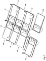
- a stable module 10, 100 which comprises a rectangular floor 12 with two opposite longitudinal edges 14, 16 and a front and a rear transverse edge 18, 20 which are also located opposite each other. Exemplary embodiments of such stable modules are shown in Figs. 1 and 4 . Further, the stable module 10, 100 comprises at least one dung discharge opening 22 which is provided in the floor 12. In the exemplary embodiments shown in the figures, the floor in each case is provided with just one dung discharge opening 22, more specifically near the rear transverse edge 20 of the floor. However, it is within the purview of the invention that the floor 12 is provided with more than one dung discharge opening 22. For instance, one near the front transverse edge 18 and one near the rear transverse edge 20.
- a dung discharge opening may also be provided along one or both of the longitudinal edges 14, 16.
- the stable module 10, 100 is provided with at least one dung trough 24 which is arranged under the floor 12 and which is associated with the at least one dung discharge opening 22, the dung trough 24 bounding a dung trough space M in which the at least one dung discharge opening 22 terminates.
- the stable module 10, 100 is provided with more than one dung discharge opening 22, then, generally, there will also be more than one dung trough 24. However, this is not requisite, for it is also possible that more than one dung discharge opening 22 terminates in a single dung trough 24.
- the dung trough 24 is generally provided with a number of dung trough walls 26-34 and with a dung drain opening 36 which is provided at an underside of the dung trough space M in one of the dung trough walls 26-34.
- the dung drain opening 36 is arranged in a dung trough bottom wall 30 of the dung trough 24.
- the dung drain opening 36 may also be provided in one of the other walls 26-34 of the dung trough 24, as long as the dung drain opening 36 terminates at the bottom of the dung trough 24.
- a dung removal channel (not shown) is connectable.
- the floor 12 provides a bearing surface on which stands or lies the at least one animal dwelling in or on the stable module.
- the floor 12 is configured to bear the at least one animal dwelling in or on the stable module.
- the floor 12 and the dung trough walls 26-34 are manufactured from prefab concrete and form a monolithic whole.
- a stable module 10, 100 is obtained which is self-supporting. This means that the stable module 10, 100 can be manufactured in a concrete factory and that on the site where the stable is to be realized, no concrete casting, at least, concrete casting on a very limited scale, needs to be carried out, at the most, perhaps, for providing a foundation that needs to comprise only a few foundation points. That is of particular importance from the viewpoint of building efficiency and hence costs.
- Self-supporting is understood to mean that the stable module 10, 100, when it is supported at its longitudinal edges 14, 16 and/or transverse edges 18, 20 and/or the dung trough bottom wall 30, can bear its own weight, the weight of animals present thereon, and the weight of any dung and liquid present in the dung trough 24.
- the stable module 10, 100 can also, at least in part, be supported on the dung trough bottom wall 30, since the dung removal conduits that are to be connected to the dung drain openings 36 can then extend next to the dung troughs 24.
- the top of the floor 12 may be of inclined or convex configuration, so that the dung being deposited thereon is easily removed to a dung discharge opening 22.
- the figures show a sloping top, which is well visible in the cross-sectional view of Fig. 6 .
- piping may be cast-in which can be connected to a heating system, so that the floor 12 may be provided with floor heating.
- Such conduits may be designed as a water conduit to which a conduit which is in communication with a boiler is connected.
- the conduits can also be electrical wires which, when connected to an electrical source, heat up as a result of the electrical resistance prevailing therein and thus generate the heat for heating the floor 12.
- the stable module 10, 100 is provided with a dung grid 38 which covers the dung discharge opening 22 and which is so configured that an animal can stand on it and that dung can be discharged through it.
- At least a part of the dung grid 38 may be an integral part of the floor 12. This can be realized, for instance, by a plurality of through-openings which are provided in the floor 12 and which terminate in the dung trough space M.
- the through openings which may for instance be designed as slots, may be integrally molded during the casting process of the monolithically formed stable module 10, 100.
- the dung grid 38 can be a loose element, while the edges of the dung discharge opening 22 are provided with a groove 41 in which the grid 38 is placeable.
- a dung grid 38 of which an example is shown in Fig. 13 , may be manufactured, for instance, from wood, plastic, concrete or metal. It is also possible that a combination is used of a dung grid which is an integral part of the floor 12 and a loose dung grid 38.
- each dung trough 24 can comprise two obliquely oriented dung trough walls 26, 28 which extend from an underside of the floor 12 in downward direction, viewed from the dung discharge opening 22, being directed obliquely towards each other and joining each other directly, or via an optional dung trough bottom wall 30, at an underside.
- the dung trough 24 can comprise two opposite dung trough end walls 32, 34 which adjoin the obliquely oriented dung trough walls 26, 28 and the floor 12.
- the obliquely oriented dung trough walls 26, 28 and the dung trough end walls 32, 34 and the optional dung trough bottom wall 30 can jointly bound the dung trough space M.
- the dung discharge opening 22 terminates in the dung trough space M.
- the dung level in the dung trough space M is kept low, there is a relatively small evaporative surface, which keeps the ammonia content in the stable low. This is of importance to the well-being and health of the animals.
- the dung trough can also have other configurations.
- a dung trough may be considered that has a rectangular cross section, or a cross section with two vertical wall parts which are connected to each other through a bottom segment having a circular segment-shaped configuration.
- a trapezium-shaped cross section could be considered where the long side of the trapezium is at the bottom and the short side of the trapezium is formed by the dung discharge opening 22 in the floor 12.
- the longitudinal edges and/or the transverse edges may be provided with grooves 14a, 16a, 18a, 20a, such that the longitudinal edges and/or the transverse edges also comprise a tongue 14b, 16b, 18b, 20b.
- the exemplary embodiments shown in the figures are provided with such grooves 14a, 16a, 18a, 20a and tongues 14b, 16b, 18b, 20b.
- the grooves 14a, 16a, 18a, 20a and tongues 14b, 16b, 18b, 20b in such embodiments are so configured that in forming a stable that comprises a plurality of stable modules, the tongue 14b, 16b, 18b, 20b of the longitudinal or transverse edge 14-20 of a stable module 10 is received in the groove 14a, 16a, 18a, 20a of a neighboring stable module 100.
- Figs. 11 and 12 which are details adjacent the junction between two neighboring stable modules 10, 100.
- the stable module 10 can comprise at least two side walls 40, 42 and a rear wall 44 which extend from the floor 12 in upward direction and which extend along the two longitudinal edges 14, 16 and the rear transverse edge 20 and which together bound an access opening to the space that is bounded by the rear wall 44 and the side walls 40, 42.
- the rear wall 44 and the side walls 40, 42 are at least partly made from prefab concrete and they form a monolithic whole with the floor 12 and the dung trough walls 26-34.
- At least one of the side walls 42 may be provided with a recess U in which a dry feed trough, drinking trough and/or wet feed trough 56 is mountable.
- Fig. 13 shows such a dry feed trough or wet feed trough 56 which is mounted in the recess.
- the stable module 10 may be provided with at least four uprights 46-52, which extend vertically upwards from the corners of the upper wall and which are manufactured from prefab concrete and form a monolithic whole with the floor 12 and the dung trough walls 26-34.
- the uprights can extend to a higher level above the floor than the side walls 40, 42 and the rear wall 44.
- slots 58 extending in vertical direction may be provided.
- loose plates, tubes or planks 60 may be slidably receivable. With such plates or planks 60, of which an example is shown in Fig. 13 , the side walls 40, 42 and the rear wall 44 can be heightened to a desired level.
- the stable module 10, 100 may further be provided with a gate 54 which is configured to close the access opening in a closed position and to clear it in an open position.
- Fig. 13 shows an example of such a gate 54 which, via a hinge, is pivotably connected to an upright 46 of the stable module 10.
- the stable modules 100 which are not provided with monolithically co-formed side and rear walls and uprights, may, when they are set up next to stable modules 10 which do comprise such side and rear walls and uprights 46-52, also be provided with a gate 54 which is then mounted to an upright 48 of one of those neighboring stable modules 10.
- the stable module 100 may specifically be not provided with a rear wall 44 and side walls 40, 42.
- stable modules 10 which are provided with side walls 40, 42 and a rear wall
- the invention hence also provides a stable which is provided with at least one row R1, R2 of modules 10, 100 according to the invention.
- An exemplary embodiment of a portion of such a stable is shown in Figs. 7-13 .
- a row R1, R2 there may be arranged next to each other, in alternation, stable modules 100 without side and rear walls 40-44 and stable modules 10 with side and rear walls 40-44.
- a large number of stable modules 100 without side walls are placed against each other for forming a large stable surface over which the animals can freely range.
- the circumferential edges of the large stable surface could be bounded by stable modules that have one or, when a stable module is involved that forms a corner of the stable surface, two walls.
- these walls could be manufactured from concrete and form a monolithic whole with the relevant stable module.
- the walls are formed by loose wall elements which are mounted to the floor 12 of the relevant stable module 100. At least some of these stable modules 100 will be provided with a dung trough 24.
- Other parts of the stable floor to be formed can consist of simple concrete slabs which are not provided with walls nor with a dung trough 24.
- a number of the stable modules may be provided with a dung discharge opening 22 and dung grid 38 whose dimensions substantially correspond to the dimensions of the relevant stable module.
- a number of such stable modules 100 may be juxtaposed with large dung discharge opening 22 next to each other, so that in the stable floor a particular continuous range, comprising more than one stable module, forms a dung discharge range.
- the stable can comprise a number of loose walls which are intended for closing the sides of the stable modules 100 which are not provided with side and rear walls.
- Such loose walls can be mounted to the side walls 40, 42 or uprights 50, 52 of the neighboring stable modules according to any one of claims 7-10. It is also possible that the loose walls are mounted on the floor 12 of the relevant stable module 100 itself.
- the stable may be provided with a number of loose gates 54 intended for closing the front sides of the stable modules 100 without side walls 40, 42 and rear wall 44.
- Each loose gate 54 can then be mounted to a side wall 40, 42 or upright 50, 52 of a neighboring stable module 10 according to any one of claims 7-10.
- the gates can also be mounted on the floor 12 of the relevant stable module 100 itself, for instance by means of a loose upright with which the gate 54 is hingedly connected, which upright is provided with a base which can be anchored to the floor 12 through bolts or like fasteners.
- the stable may be provided with at least two rows R1, R2, with each row R1, R2 having a front and a rear, with the front edges 18 of the floors 12 of the stable modules 10; 100 defining the front, and the rear edges 20 of the floors 12 defining the rear of the row R1, R2.
- a gangway G extends.
- the gangway G may be provided with grids and under these grids an exhaust installation or an air supply installation may be set up for respectively discharging polluted air from and supplying fresh air into the stable.
- the fronts of two neighboring rows R1, R2 may face each other, with the gangway G extending between the two mutually facing fronts.
- the fronts of two neighboring rows R1, R2 may face each other, with the gangway G extending between the two mutually facing fronts.
- the stable modules 10, 100 shown in the exemplary embodiments preferably have a maximum width of 2.6 m, so that they can still be transported by truck.
- the length of the floor 12 can be, for instance, 4.6 m.
- the height of the side and rear walls forming a monolithic whole with the floor 12 can be, for instance, 0.6 m, and the height of the uprights 45-52, integrally cast in concrete, can be, for instance, 1.1 m.
- the width of the dung trough 24 is less than the distance between two side walls 40, 42.
- a stable module 100 without side and rear walls 40-42 and a stable module 10 with side and rear walls can be placed onto each other with the undersides facing each other, so that the two modules together have a height of about 0.8 m when they are not provided with uprights, and about 1.4 m when they do comprise uprights 46-52.
- On a truck three to five of such pairs of stable modules 10, 100 can be conveyed, so that per truck 6 to 10 stable modules 10, 100 can be conveyed.
- stables can be built that comprise multiple tiers.
- the monolithic concrete construction of a stable module 10, 100 is self-supporting, that is, the stable module 10, 100, when it is supported at its longitudinal edges 14, 16 and/or transverse edges 18, 20 and/or underside of the dung trough, can bear its own weight, the weight of animals present thereon, as well as the weight of any dung and liquid present in the dung trough 24.
- Such other stable modules may for instance comprise a floor but not be provided with integrally molded dung troughs 24.
- Such other stable modules possibly do comprise dung removal openings which can then terminate in a dung removal channel to be separately laid.
- Such other stable modules may or may not be provided with side and/or rear walls which are co-formed with the floor.
- the feeding trough, drinking trough and/or wet feed trough 56 may be integrally formed in the stable module 10, 100 and therefore be part of the monolithic concrete construction which also comprises the floor 12, the dung trough walls 26-34 and any side and rear walls 40-42.
Landscapes
- Life Sciences & Earth Sciences (AREA)
- Environmental Sciences (AREA)
- Zoology (AREA)
- Animal Husbandry (AREA)
- Biodiversity & Conservation Biology (AREA)
- Housing For Livestock And Birds (AREA)
Claims (18)
- Module d'étable (10 ; 100) comprenant :• un plancher rectangulaire (12) ayant deux bords longitudinaux opposés (14, 16) et un bord transversal avant et un bord transversal arrière (18, 20) qui sont positionnés à l'opposé l'un de l'autre ;• au moins une ouverture de décharge de bouse (22) qui est prévue dans le plancher (12) ;• au moins une goulotte de bouse (24) qui est agencée sous le plancher (12) et est associée avec la au moins une ouverture de décharge de bouse (22), dans lequel la goulotte de bouse (24) délimite un espace de goulotte de bouse (M) dans lequel la au moins une ouverture de décharge de bouse (22) débouche,dans laquelle la goulotte de bouse (24) comprend :o un certain nombre de parois de goulotte de bouse (26-34) ; eto une ouverture d'évacuation de bouse (36) qui est prévue au niveau d'une face inférieure de l'espace de goulotte de bouse (M) dans l'une des parois de goulotte de bouse (26-34) et auquel un canal de retrait de bouse peut être raccordé ;caractérisé en ce que le plancher (12) comprend une surface d'appui sur laquelle le au moins un animal séjournant dans ou sur le module d'étable se tient droit et se couche, dans lequel le plancher (12) est configuré pour supporter le au moins un animal séjournant dans ou sur le module d'étable, et dans lequel le plancher (12) et les parois de goulotte de bouse (26-34) sont fabriqués à partir de béton préfabriqué et forment un ensemble monolithique qui est autoporteur.
- Module d'étable selon la revendication 1, prévu avec :• une grille de bouse (38) qui recouvre l'ouverture de décharge de bouse (22) et est configurée de sorte que un animal peut se tenir debout sur cette dernière et à travers laquelle la bouse peut être déchargée.
- Module d'étable selon la revendication 2, dans lequel au moins une partie de la grille de bouse (38) est une partie intégrante du plancher (12) et comprend une pluralité d'ouvertures débouchantes dans le plancher (12) qui débouchent dans l'espace de goulotte de bouse (M).
- Module d'étable selon la revendication 2, dans lequel la grille de bouse (38) est un élément libre, alors que les bords de l'ouverture de décharge de bouse (22) sont prévus avec une rainure (41) dans laquelle la grille (38) peut être placée.
- Module d'étable selon l'une quelconque des revendications 1 à 4, dans lequel chaque goulotte de bouse comprend :o deux parois de goulotte de bouse (26, 28) orientées de manière oblique, qui s'étendent à partir d'une face inférieure du plancher (12) dans la direction descendante, observées à partir de l'ouverture de décharge de bouse (22), dirigées l'une vers l'autre, et au niveau d'une face inférieure, sont directement attenantes, ou via une paroi inférieure de goulotte de bouse (30) facultative ; eto deux parois d'extrémité de goulotte de bouse opposées (32, 34) qui sont attenantes aux parois de goulotte de bouse (26, 28) orientées de manière oblique et au plancher (12), dans lequel les parois de goulotte de bouse (26, 28) orientées de manière oblique et les parois d'extrémité de goulotte de bouse (32, 34) et la paroi inférieure de goulotte de bouse facultative (30) délimitent ensemble l'espace de goulotte de bouse (M), alors que l'ouverture de décharge de bouse (22) débouche dans l'espace de goulotte de bouse (M).
- Module d'étable selon l'une quelconque des revendications 1 à 5, dans lequel les bords longitudinaux et/ou les bords transversaux sont prévus avec des rainures (14a, 16a, 18a, 20a) de sorte que les bords longitudinaux et/ou les bords transversaux comprennent également une languette (14b, 16b, 18b, 20b) et configurés de sorte que pour former une étable qui comprend une pluralité de modules d'étable, la languette (14b, 16b, 18b, 20b) du bord longitudinal ou transversal d'un module d'étable est reçue dans la rainure (14a, 16a, 18a, 20a) d'un module d'étable voisin.
- Module d'étable (10) selon l'une quelconque des revendications 1 à 6, comprenant :• au moins deux parois latérales (40, 42) et une paroi arrière (44) qui s'étendent à partir du plancher (12) dans la direction ascendante et qui s'étendent le long des deux bords longitudinaux (14, 16) et du bord transversal arrière (20), respectivement, et qui délimitent ensemble une ouverture d'accès à l'espace qui est délimité par la paroi arrière (44) et les parois latérales (40, 42), dans lequel la paroi arrière (44) et les parois latérales (40, 42) sont fabriquées à partir de béton préfabriqué et forment un ensemble monolithique avec le plancher (12) et les parois de goulotte de bouse (26-34).
- Module d'étable selon la revendication 7, dans lequel l'une des parois latérales (42) est prévue avec un évidemment (U) dans lequel une mangeoire pour alimentation sèche, un abreuvoir et/ou une mangeoire pour alimentation mouillée (56) peuvent être montés.
- Module d'étable selon l'une quelconque des revendications 7 à 8, comprenant :• au moins quatre montants (46-52) qui s'étendent verticalement vers le haut à partir des points de coin de la paroi supérieure et qui sont fabriqués à partir de béton préfabriqué et forment un ensemble monolithique avec le plancher (12) et les parois de goulotte de bouse (26-34), dans lequel les montants peuvent s'étendre jusqu'à un niveau plus élevé au-dessus du plancher que les parois latérales (40, 42) et la paroi arrière (44), dans lequel, dans les montants (46-52), on prévoit des fentes (58) s'étendant dans la direction verticale, dans lesquelles des plaques libres, des tubes ou des planches (60) peuvent être reçus de manière coulissante.
- Module d'étable selon l'une quelconque des revendications 7 à 9, prévu avec :• une barrière (54) qui est configurée pour fermer l'ouverture d'accès dans une position fermée et la dégager dans une position ouverte.
- Module d'étable (100) selon l'une quelconque des revendications 1 à 6,
dans lequel le module d'étable (100) n'est pas prévu avec une paroi arrière (44) ni avec des parois latérales (40, 42). - Etable fournie avec au moins une rangée de modules d'étable (10, 100), selon l'une quelconque des revendications 1 à 11.
- Etable selon la revendication 12, dans laquelle, dans la rangée, on agence les uns à côté des autres, en alternance :• des modules d'étable selon la revendication 11 ; et• des modules d'étable selon l'une quelconque des revendications 7 à 10.
- Etable selon la revendication 12 ou 13, prévue avec :• un certain nombre de parois libres prévues pour fermer au moins un côté particulier souhaité d'au moins l'un des modules d'étable (100) selon la revendication 11, dans laquelle chaque paroi libre est montée sur le plancher (12) du module d'étable (100) approprié ou sur les parois latérales (40, 42) ou les montants (50, 52) des modules d'étable (10) voisins selon l'une quelconque des revendications 7 à 10.
- Etable selon l'une quelconque des revendications 12 à 14, prévue avec :• un certain nombre de barrières libres (54) prévues pour fermer un côté souhaité d'au moins l'un des modules d'étable (100) selon la revendication 11, dans laquelle chaque barrière libre (54) est montée sur le plancher (12) du module d'étable (100) approprié ou sur une paroi latérale (40, 42) ou un montant (46, 48) d'un module d'étable (10) voisin selon l'une quelconque des revendications 7 à 10.
- Etable selon l'une quelconque des revendications 12 à 15, prévue avec au moins deux rangées (R1, R2), avec chaque rangée (R1, R2) qui a une partie avant et une partie arrière, avec les bords avant (18) des planchers (12) des modules d'étable (10 ; 100) qui définissent la partie avant, et les bords arrière (20) des planchers (12) qui définissent la partie arrière de la rangée (R1, R2), dans laquelle le long de la partie avant d'une rangée, s'étend une passerelle (G).
- Etable selon la revendication 16, dans laquelle les parties avant des deux rangées (R1, R2) voisines se font face, dans laquelle entre les deux parties avant mutuellement en vis-à-vis, s'étend la passerelle (G).
- Etable selon la revendication 16 ou 17, dans laquelle les côtés arrière des deux rangées (R1, R3) voisines se font face et sont placés l'un contre l'autre sans espaces intermédiaires.
Applications Claiming Priority (1)
| Application Number | Priority Date | Filing Date | Title |
|---|---|---|---|
| NL2011379A NL2011379C2 (nl) | 2013-09-04 | 2013-09-04 | Stalmodule alsmede stal opgebouwd uit dergelijke stalmodules. |
Publications (2)
| Publication Number | Publication Date |
|---|---|
| EP2845472A1 EP2845472A1 (fr) | 2015-03-11 |
| EP2845472B1 true EP2845472B1 (fr) | 2016-06-22 |
Family
ID=49447788
Family Applications (1)
| Application Number | Title | Priority Date | Filing Date |
|---|---|---|---|
| EP14183584.3A Active EP2845472B1 (fr) | 2013-09-04 | 2014-09-04 | Structure modulaire pour étable et étable avec telles structures |
Country Status (7)
| Country | Link |
|---|---|
| EP (1) | EP2845472B1 (fr) |
| DK (1) | DK2845472T3 (fr) |
| ES (1) | ES2589228T3 (fr) |
| HU (1) | HUE031012T2 (fr) |
| NL (1) | NL2011379C2 (fr) |
| PL (1) | PL2845472T3 (fr) |
| PT (1) | PT2845472T (fr) |
Families Citing this family (2)
| Publication number | Priority date | Publication date | Assignee | Title |
|---|---|---|---|---|
| FR3079999B1 (fr) * | 2018-04-13 | 2021-04-02 | Fournier | Module de plancher d'un batiment d'elevage, et plancher correspondant |
| CN109303002A (zh) * | 2018-11-01 | 2019-02-05 | 黄梅县强立畜牧有限公司 | 一种生态环保型养猪场 |
Family Cites Families (4)
| Publication number | Priority date | Publication date | Assignee | Title |
|---|---|---|---|---|
| FR2724289B1 (fr) * | 1994-09-08 | 1997-01-24 | I Tek Sa | Bac de recuperation de lisier |
| NL1004036C2 (nl) * | 1996-09-16 | 1998-03-17 | Antonius Maria Aloysius Nooyen | Stalinrichting, bak te gebruiken bij de stalinrichting en werkwijze voor het houden van dieren. |
| DE102004028134A1 (de) * | 2004-06-09 | 2005-12-29 | Hartmann Gmbh | Betonfertigteil als Liegemulde für Kühe |
| DE102004061547B3 (de) * | 2004-12-21 | 2006-05-04 | Hartmann Grundbesitz Gmbh & Co. Kg | Betonfertigteilesystem für einen Stallboden, ein diesen Stallboden umfassender Stall und Verfahren zu seiner Herstellung |
-
2013
- 2013-09-04 NL NL2011379A patent/NL2011379C2/nl not_active IP Right Cessation
-
2014
- 2014-09-04 HU HUE14183584A patent/HUE031012T2/en unknown
- 2014-09-04 PT PT141835843T patent/PT2845472T/pt unknown
- 2014-09-04 ES ES14183584.3T patent/ES2589228T3/es active Active
- 2014-09-04 DK DK14183584.3T patent/DK2845472T3/en active
- 2014-09-04 PL PL14183584.3T patent/PL2845472T3/pl unknown
- 2014-09-04 EP EP14183584.3A patent/EP2845472B1/fr active Active
Also Published As
| Publication number | Publication date |
|---|---|
| EP2845472A1 (fr) | 2015-03-11 |
| NL2011379C2 (nl) | 2015-03-09 |
| PT2845472T (pt) | 2016-09-08 |
| ES2589228T3 (es) | 2016-11-11 |
| PL2845472T3 (pl) | 2016-12-30 |
| DK2845472T3 (en) | 2016-09-12 |
| HUE031012T2 (en) | 2017-06-28 |
Similar Documents
| Publication | Publication Date | Title |
|---|---|---|
| US8950112B2 (en) | Device for a vertical or angled arrangement of the hydroponic cultivation of plants | |
| US8978300B2 (en) | Post or wall mounted stackable plant pot | |
| EP2845472B1 (fr) | Structure modulaire pour étable et étable avec telles structures | |
| EP3162196B1 (fr) | Élément de plancher cannelé pour une étable, un substrat et un tapis flexible | |
| KR101179544B1 (ko) | 인공 조경 시스템 | |
| EP3749088B1 (fr) | Appareil de collecte et d'enlèvement de lisier | |
| CN214430927U (zh) | 一种集成装配式多层养猪设备 | |
| WO2018029146A1 (fr) | Dispositif de collecte et d'élimination de boue, porcherie pourvue d'un tel dispositif et procédé d'installation d'un tel dispositif | |
| EP3348139A1 (fr) | Système modulaire pour la construction d'une porcherie dotée de canaux à fumier et porcherie comprenant un tel système modulaire | |
| NL1038277C2 (nl) | Werkwijze en stelsel voor het met plantenbakken en/of panelen bedekken van een structuur zoals een wand of dak, alsmede bevestigingsmiddelen, bakken en panelen als deel van een dergelijk stelsel, alsmede een geluidsscherm voorzien van een dergelijk stelsel. | |
| SI3011830T1 (en) | PREFABRICATED MODEL FOR FLOOR LIVESTOCK FOR ANIMAL | |
| CN223793606U (zh) | 一种养殖场舍基坑支护结构 | |
| EP3079462A1 (fr) | Auge longue | |
| CN212344894U (zh) | 凸出式料道牛栏 | |
| JP2012060905A (ja) | 植栽ユニットとこれを用いた植栽ユニットシステム | |
| PL133620B1 (en) | Set of cages for growing small animals | |
| DK175242B1 (da) | Fremgangsmåde til indvendig staldopbygning samt element til brug ved fremgangsmåden | |
| KR20250046808A (ko) | 축사의 열교환장치 | |
| NZ777690A (en) | Module and assembly for underground management of fluids for shallow-depth applications | |
| NZ777690B2 (en) | Module and assembly for underground management of fluids for shallow-depth applications | |
| NL1034475C2 (nl) | Begrenzingswand, wandelement voor een dergelijke begrenzingswand en werkwijze voor het vervaardigen van een dergelijk wandelement. | |
| CN117396067A (zh) | 用于动物饲养建筑物的模块化底板组件,相应的底板和建筑物,以及建立采用模块化底板组件的建筑物的方法 | |
| CN111789033A (zh) | 凸出式料道牛栏 | |
| DK201770080A1 (en) | A device for collection and removal of slurry and a method for installing such a device | |
| RO125746A2 (ro) | Grajd integral |
Legal Events
| Date | Code | Title | Description |
|---|---|---|---|
| 17P | Request for examination filed |
Effective date: 20140904 |
|
| AK | Designated contracting states |
Kind code of ref document: A1 Designated state(s): AL AT BE BG CH CY CZ DE DK EE ES FI FR GB GR HR HU IE IS IT LI LT LU LV MC MK MT NL NO PL PT RO RS SE SI SK SM TR |
|
| AX | Request for extension of the european patent |
Extension state: BA ME |
|
| PUAI | Public reference made under article 153(3) epc to a published international application that has entered the european phase |
Free format text: ORIGINAL CODE: 0009012 |
|
| R17P | Request for examination filed (corrected) |
Effective date: 20150825 |
|
| RBV | Designated contracting states (corrected) |
Designated state(s): AL AT BE BG CH CY CZ DE DK EE ES FI FR GB GR HR HU IE IS IT LI LT LU LV MC MK MT NL NO PL PT RO RS SE SI SK SM TR |
|
| GRAP | Despatch of communication of intention to grant a patent |
Free format text: ORIGINAL CODE: EPIDOSNIGR1 |
|
| INTG | Intention to grant announced |
Effective date: 20160118 |
|
| GRAS | Grant fee paid |
Free format text: ORIGINAL CODE: EPIDOSNIGR3 |
|
| GRAA | (expected) grant |
Free format text: ORIGINAL CODE: 0009210 |
|
| AK | Designated contracting states |
Kind code of ref document: B1 Designated state(s): AL AT BE BG CH CY CZ DE DK EE ES FI FR GB GR HR HU IE IS IT LI LT LU LV MC MK MT NL NO PL PT RO RS SE SI SK SM TR |
|
| REG | Reference to a national code |
Ref country code: GB Ref legal event code: FG4D |
|
| REG | Reference to a national code |
Ref country code: CH Ref legal event code: EP |
|
| REG | Reference to a national code |
Ref country code: IE Ref legal event code: FG4D |
|
| REG | Reference to a national code |
Ref country code: AT Ref legal event code: REF Ref document number: 807096 Country of ref document: AT Kind code of ref document: T Effective date: 20160715 |
|
| REG | Reference to a national code |
Ref country code: DE Ref legal event code: R096 Ref document number: 602014002391 Country of ref document: DE |
|
| REG | Reference to a national code |
Ref country code: RO Ref legal event code: EPE |
|
| REG | Reference to a national code |
Ref country code: PT Ref legal event code: SC4A Ref document number: 2845472 Country of ref document: PT Date of ref document: 20160908 Kind code of ref document: T Free format text: AVAILABILITY OF NATIONAL TRANSLATION Effective date: 20160901 |
|
| REG | Reference to a national code |
Ref country code: DK Ref legal event code: T3 Effective date: 20160906 |
|
| REG | Reference to a national code |
Ref country code: SE Ref legal event code: TRGR |
|
| REG | Reference to a national code |
Ref country code: FR Ref legal event code: PLFP Year of fee payment: 3 Ref country code: NL Ref legal event code: FP |
|
| REG | Reference to a national code |
Ref country code: LT Ref legal event code: MG4D |
|
| PG25 | Lapsed in a contracting state [announced via postgrant information from national office to epo] |
Ref country code: LT Free format text: LAPSE BECAUSE OF FAILURE TO SUBMIT A TRANSLATION OF THE DESCRIPTION OR TO PAY THE FEE WITHIN THE PRESCRIBED TIME-LIMIT Effective date: 20160622 Ref country code: FI Free format text: LAPSE BECAUSE OF FAILURE TO SUBMIT A TRANSLATION OF THE DESCRIPTION OR TO PAY THE FEE WITHIN THE PRESCRIBED TIME-LIMIT Effective date: 20160622 Ref country code: NO Free format text: LAPSE BECAUSE OF FAILURE TO SUBMIT A TRANSLATION OF THE DESCRIPTION OR TO PAY THE FEE WITHIN THE PRESCRIBED TIME-LIMIT Effective date: 20160922 |
|
| REG | Reference to a national code |
Ref country code: ES Ref legal event code: FG2A Ref document number: 2589228 Country of ref document: ES Kind code of ref document: T3 Effective date: 20161111 |
|
| PG25 | Lapsed in a contracting state [announced via postgrant information from national office to epo] |
Ref country code: RS Free format text: LAPSE BECAUSE OF FAILURE TO SUBMIT A TRANSLATION OF THE DESCRIPTION OR TO PAY THE FEE WITHIN THE PRESCRIBED TIME-LIMIT Effective date: 20160622 Ref country code: LV Free format text: LAPSE BECAUSE OF FAILURE TO SUBMIT A TRANSLATION OF THE DESCRIPTION OR TO PAY THE FEE WITHIN THE PRESCRIBED TIME-LIMIT Effective date: 20160622 Ref country code: GR Free format text: LAPSE BECAUSE OF FAILURE TO SUBMIT A TRANSLATION OF THE DESCRIPTION OR TO PAY THE FEE WITHIN THE PRESCRIBED TIME-LIMIT Effective date: 20160923 Ref country code: HR Free format text: LAPSE BECAUSE OF FAILURE TO SUBMIT A TRANSLATION OF THE DESCRIPTION OR TO PAY THE FEE WITHIN THE PRESCRIBED TIME-LIMIT Effective date: 20160622 |
|
| PG25 | Lapsed in a contracting state [announced via postgrant information from national office to epo] |
Ref country code: EE Free format text: LAPSE BECAUSE OF FAILURE TO SUBMIT A TRANSLATION OF THE DESCRIPTION OR TO PAY THE FEE WITHIN THE PRESCRIBED TIME-LIMIT Effective date: 20160622 Ref country code: CZ Free format text: LAPSE BECAUSE OF FAILURE TO SUBMIT A TRANSLATION OF THE DESCRIPTION OR TO PAY THE FEE WITHIN THE PRESCRIBED TIME-LIMIT Effective date: 20160622 Ref country code: IS Free format text: LAPSE BECAUSE OF FAILURE TO SUBMIT A TRANSLATION OF THE DESCRIPTION OR TO PAY THE FEE WITHIN THE PRESCRIBED TIME-LIMIT Effective date: 20161022 Ref country code: SK Free format text: LAPSE BECAUSE OF FAILURE TO SUBMIT A TRANSLATION OF THE DESCRIPTION OR TO PAY THE FEE WITHIN THE PRESCRIBED TIME-LIMIT Effective date: 20160622 |
|
| PG25 | Lapsed in a contracting state [announced via postgrant information from national office to epo] |
Ref country code: SM Free format text: LAPSE BECAUSE OF FAILURE TO SUBMIT A TRANSLATION OF THE DESCRIPTION OR TO PAY THE FEE WITHIN THE PRESCRIBED TIME-LIMIT Effective date: 20160622 |
|
| REG | Reference to a national code |
Ref country code: DE Ref legal event code: R097 Ref document number: 602014002391 Country of ref document: DE |
|
| PG25 | Lapsed in a contracting state [announced via postgrant information from national office to epo] |
Ref country code: MC Free format text: LAPSE BECAUSE OF FAILURE TO SUBMIT A TRANSLATION OF THE DESCRIPTION OR TO PAY THE FEE WITHIN THE PRESCRIBED TIME-LIMIT Effective date: 20160622 |
|
| PLBE | No opposition filed within time limit |
Free format text: ORIGINAL CODE: 0009261 |
|
| STAA | Information on the status of an ep patent application or granted ep patent |
Free format text: STATUS: NO OPPOSITION FILED WITHIN TIME LIMIT |
|
| 26N | No opposition filed |
Effective date: 20170323 |
|
| REG | Reference to a national code |
Ref country code: HU Ref legal event code: AG4A Ref document number: E031012 Country of ref document: HU |
|
| PG25 | Lapsed in a contracting state [announced via postgrant information from national office to epo] |
Ref country code: LU Free format text: LAPSE BECAUSE OF NON-PAYMENT OF DUE FEES Effective date: 20160904 Ref country code: SI Free format text: LAPSE BECAUSE OF FAILURE TO SUBMIT A TRANSLATION OF THE DESCRIPTION OR TO PAY THE FEE WITHIN THE PRESCRIBED TIME-LIMIT Effective date: 20160622 |
|
| REG | Reference to a national code |
Ref country code: FR Ref legal event code: PLFP Year of fee payment: 4 |
|
| REG | Reference to a national code |
Ref country code: CH Ref legal event code: PL |
|
| PG25 | Lapsed in a contracting state [announced via postgrant information from national office to epo] |
Ref country code: CY Free format text: LAPSE BECAUSE OF FAILURE TO SUBMIT A TRANSLATION OF THE DESCRIPTION OR TO PAY THE FEE WITHIN THE PRESCRIBED TIME-LIMIT Effective date: 20160622 Ref country code: MT Free format text: LAPSE BECAUSE OF NON-PAYMENT OF DUE FEES Effective date: 20160930 Ref country code: MK Free format text: LAPSE BECAUSE OF FAILURE TO SUBMIT A TRANSLATION OF THE DESCRIPTION OR TO PAY THE FEE WITHIN THE PRESCRIBED TIME-LIMIT Effective date: 20160622 |
|
| PG25 | Lapsed in a contracting state [announced via postgrant information from national office to epo] |
Ref country code: BG Free format text: LAPSE BECAUSE OF FAILURE TO SUBMIT A TRANSLATION OF THE DESCRIPTION OR TO PAY THE FEE WITHIN THE PRESCRIBED TIME-LIMIT Effective date: 20160622 Ref country code: LI Free format text: LAPSE BECAUSE OF NON-PAYMENT OF DUE FEES Effective date: 20170930 Ref country code: CH Free format text: LAPSE BECAUSE OF NON-PAYMENT OF DUE FEES Effective date: 20170930 |
|
| REG | Reference to a national code |
Ref country code: FR Ref legal event code: PLFP Year of fee payment: 5 |
|
| PG25 | Lapsed in a contracting state [announced via postgrant information from national office to epo] |
Ref country code: TR Free format text: LAPSE BECAUSE OF FAILURE TO SUBMIT A TRANSLATION OF THE DESCRIPTION OR TO PAY THE FEE WITHIN THE PRESCRIBED TIME-LIMIT Effective date: 20160622 Ref country code: AL Free format text: LAPSE BECAUSE OF FAILURE TO SUBMIT A TRANSLATION OF THE DESCRIPTION OR TO PAY THE FEE WITHIN THE PRESCRIBED TIME-LIMIT Effective date: 20160622 |
|
| REG | Reference to a national code |
Ref country code: AT Ref legal event code: UEP Ref document number: 807096 Country of ref document: AT Kind code of ref document: T Effective date: 20160622 |
|
| PGFP | Annual fee paid to national office [announced via postgrant information from national office to epo] |
Ref country code: PT Payment date: 20250829 Year of fee payment: 12 |
|
| PGFP | Annual fee paid to national office [announced via postgrant information from national office to epo] |
Ref country code: DK Payment date: 20250923 Year of fee payment: 12 Ref country code: DE Payment date: 20250919 Year of fee payment: 12 |
|
| PGFP | Annual fee paid to national office [announced via postgrant information from national office to epo] |
Ref country code: PL Payment date: 20250829 Year of fee payment: 12 Ref country code: NL Payment date: 20250918 Year of fee payment: 12 Ref country code: IT Payment date: 20250923 Year of fee payment: 12 |
|
| PGFP | Annual fee paid to national office [announced via postgrant information from national office to epo] |
Ref country code: HU Payment date: 20250922 Year of fee payment: 12 Ref country code: BE Payment date: 20250918 Year of fee payment: 12 Ref country code: GB Payment date: 20250918 Year of fee payment: 12 |
|
| PGFP | Annual fee paid to national office [announced via postgrant information from national office to epo] |
Ref country code: FR Payment date: 20250922 Year of fee payment: 12 Ref country code: AT Payment date: 20250919 Year of fee payment: 12 |
|
| PGFP | Annual fee paid to national office [announced via postgrant information from national office to epo] |
Ref country code: SE Payment date: 20250918 Year of fee payment: 12 |
|
| PGFP | Annual fee paid to national office [announced via postgrant information from national office to epo] |
Ref country code: IE Payment date: 20250918 Year of fee payment: 12 |
|
| PGFP | Annual fee paid to national office [announced via postgrant information from national office to epo] |
Ref country code: RO Payment date: 20250901 Year of fee payment: 12 |
|
| PGFP | Annual fee paid to national office [announced via postgrant information from national office to epo] |
Ref country code: ES Payment date: 20251028 Year of fee payment: 12 |