EP2844820B1 - Installation comprising seabed-to-surface connections of the multi-riser hybrid tower type, including positive-buoyancy flexible pipes - Google Patents
Installation comprising seabed-to-surface connections of the multi-riser hybrid tower type, including positive-buoyancy flexible pipes Download PDFInfo
- Publication number
- EP2844820B1 EP2844820B1 EP13715349.0A EP13715349A EP2844820B1 EP 2844820 B1 EP2844820 B1 EP 2844820B1 EP 13715349 A EP13715349 A EP 13715349A EP 2844820 B1 EP2844820 B1 EP 2844820B1
- Authority
- EP
- European Patent Office
- Prior art keywords
- risers
- pipes
- tower
- floats
- flexible
- Prior art date
- Legal status (The legal status is an assumption and is not a legal conclusion. Google has not performed a legal analysis and makes no representation as to the accuracy of the status listed.)
- Active
Links
- 230000009975 flexible effect Effects 0.000 title claims description 213
- 238000009434 installation Methods 0.000 title claims description 57
- 238000007667 floating Methods 0.000 claims description 66
- 239000000463 material Substances 0.000 claims description 32
- 230000000284 resting effect Effects 0.000 claims description 28
- 238000009413 insulation Methods 0.000 claims description 19
- 244000261422 Lysimachia clethroides Species 0.000 claims description 10
- 238000000034 method Methods 0.000 claims description 6
- 239000002131 composite material Substances 0.000 claims description 5
- 230000002706 hydrostatic effect Effects 0.000 claims description 5
- 230000002093 peripheral effect Effects 0.000 claims description 4
- 238000003466 welding Methods 0.000 claims description 4
- 229920003023 plastic Polymers 0.000 claims description 3
- 239000004033 plastic Substances 0.000 claims description 3
- 230000001681 protective effect Effects 0.000 claims description 2
- 238000010397 one-hybrid screening Methods 0.000 claims 1
- 210000002435 tendon Anatomy 0.000 description 102
- XLYOFNOQVPJJNP-UHFFFAOYSA-N water Substances O XLYOFNOQVPJJNP-UHFFFAOYSA-N 0.000 description 29
- 238000004519 manufacturing process Methods 0.000 description 28
- 150000001875 compounds Chemical class 0.000 description 18
- 239000003921 oil Substances 0.000 description 13
- 235000019198 oils Nutrition 0.000 description 13
- 239000004014 plasticizer Substances 0.000 description 13
- 230000007704 transition Effects 0.000 description 12
- 229920000642 polymer Polymers 0.000 description 10
- 239000011810 insulating material Substances 0.000 description 9
- 239000000203 mixture Substances 0.000 description 7
- 230000002829 reductive effect Effects 0.000 description 7
- 239000013535 sea water Substances 0.000 description 7
- 230000008901 benefit Effects 0.000 description 6
- 230000006835 compression Effects 0.000 description 6
- 238000007906 compression Methods 0.000 description 6
- 239000012530 fluid Substances 0.000 description 6
- 239000011159 matrix material Substances 0.000 description 6
- 239000004005 microsphere Substances 0.000 description 6
- -1 polypropylene Polymers 0.000 description 6
- 235000015112 vegetable and seed oil Nutrition 0.000 description 6
- 239000008158 vegetable oil Substances 0.000 description 6
- 238000004873 anchoring Methods 0.000 description 5
- 239000010779 crude oil Substances 0.000 description 5
- 230000000694 effects Effects 0.000 description 5
- 239000006260 foam Substances 0.000 description 5
- 238000002955 isolation Methods 0.000 description 5
- 239000011325 microbead Substances 0.000 description 5
- 239000003208 petroleum Substances 0.000 description 5
- 229920001228 polyisocyanate Polymers 0.000 description 5
- 239000005056 polyisocyanate Substances 0.000 description 5
- 239000004814 polyurethane Substances 0.000 description 5
- 229920002635 polyurethane Polymers 0.000 description 5
- 239000010959 steel Substances 0.000 description 5
- 208000031968 Cadaver Diseases 0.000 description 4
- XEEYBQQBJWHFJM-UHFFFAOYSA-N Iron Chemical compound [Fe] XEEYBQQBJWHFJM-UHFFFAOYSA-N 0.000 description 4
- 238000011161 development Methods 0.000 description 4
- 230000018109 developmental process Effects 0.000 description 4
- 229940082150 encore Drugs 0.000 description 4
- 150000002148 esters Chemical class 0.000 description 4
- 239000011521 glass Substances 0.000 description 4
- 229930195733 hydrocarbon Natural products 0.000 description 4
- 150000002430 hydrocarbons Chemical class 0.000 description 4
- 238000002347 injection Methods 0.000 description 4
- 239000007924 injection Substances 0.000 description 4
- 238000005304 joining Methods 0.000 description 4
- 229910052751 metal Inorganic materials 0.000 description 4
- 239000002184 metal Substances 0.000 description 4
- UPMLOUAZCHDJJD-UHFFFAOYSA-N 4,4'-Diphenylmethane Diisocyanate Chemical compound C1=CC(N=C=O)=CC=C1CC1=CC=C(N=C=O)C=C1 UPMLOUAZCHDJJD-UHFFFAOYSA-N 0.000 description 3
- 239000004215 Carbon black (E152) Substances 0.000 description 3
- 239000004698 Polyethylene Substances 0.000 description 3
- 239000004743 Polypropylene Substances 0.000 description 3
- 229910000831 Steel Inorganic materials 0.000 description 3
- 239000011324 bead Substances 0.000 description 3
- 229920006037 cross link polymer Polymers 0.000 description 3
- 238000004132 cross linking Methods 0.000 description 3
- 230000001186 cumulative effect Effects 0.000 description 3
- 239000006261 foam material Substances 0.000 description 3
- 230000002452 interceptive effect Effects 0.000 description 3
- 229920000573 polyethylene Polymers 0.000 description 3
- 229920005862 polyol Polymers 0.000 description 3
- 150000003077 polyols Chemical class 0.000 description 3
- 229920001155 polypropylene Polymers 0.000 description 3
- 238000003860 storage Methods 0.000 description 3
- 229920001169 thermoplastic Polymers 0.000 description 3
- 239000004416 thermosoftening plastic Substances 0.000 description 3
- 229910000838 Al alloy Inorganic materials 0.000 description 2
- 229910000851 Alloy steel Inorganic materials 0.000 description 2
- RYGMFSIKBFXOCR-UHFFFAOYSA-N Copper Chemical compound [Cu] RYGMFSIKBFXOCR-UHFFFAOYSA-N 0.000 description 2
- 229910000881 Cu alloy Inorganic materials 0.000 description 2
- 240000002228 Cynara humilis Species 0.000 description 2
- 235000005921 Cynara humilis Nutrition 0.000 description 2
- 241000196324 Embryophyta Species 0.000 description 2
- 229910000640 Fe alloy Inorganic materials 0.000 description 2
- 235000010469 Glycine max Nutrition 0.000 description 2
- 241000861223 Issus Species 0.000 description 2
- 239000004952 Polyamide Substances 0.000 description 2
- 235000019484 Rapeseed oil Nutrition 0.000 description 2
- 235000019486 Sunflower oil Nutrition 0.000 description 2
- 241001080024 Telles Species 0.000 description 2
- 240000008042 Zea mays Species 0.000 description 2
- XAGFODPZIPBFFR-UHFFFAOYSA-N aluminium Chemical compound [Al] XAGFODPZIPBFFR-UHFFFAOYSA-N 0.000 description 2
- 238000012550 audit Methods 0.000 description 2
- 230000033228 biological regulation Effects 0.000 description 2
- 230000008859 change Effects 0.000 description 2
- 239000000470 constituent Substances 0.000 description 2
- 239000010949 copper Substances 0.000 description 2
- 230000007423 decrease Effects 0.000 description 2
- 238000009826 distribution Methods 0.000 description 2
- 238000000605 extraction Methods 0.000 description 2
- 239000000446 fuel Substances 0.000 description 2
- 239000003502 gasoline Substances 0.000 description 2
- 239000008240 homogeneous mixture Substances 0.000 description 2
- 238000002513 implantation Methods 0.000 description 2
- 239000003350 kerosene Substances 0.000 description 2
- 230000000670 limiting effect Effects 0.000 description 2
- 239000007788 liquid Substances 0.000 description 2
- 229910001092 metal group alloy Inorganic materials 0.000 description 2
- 239000002480 mineral oil Substances 0.000 description 2
- 230000008520 organization Effects 0.000 description 2
- 229920002647 polyamide Polymers 0.000 description 2
- 229920000915 polyvinyl chloride Polymers 0.000 description 2
- 239000004800 polyvinyl chloride Substances 0.000 description 2
- 238000011084 recovery Methods 0.000 description 2
- 230000009467 reduction Effects 0.000 description 2
- 230000002787 reinforcement Effects 0.000 description 2
- 239000007787 solid Substances 0.000 description 2
- 239000002600 sunflower oil Substances 0.000 description 2
- 239000000725 suspension Substances 0.000 description 2
- 229920002994 synthetic fiber Polymers 0.000 description 2
- 238000012546 transfer Methods 0.000 description 2
- 241000195940 Bryophyta Species 0.000 description 1
- 241001415961 Gaviidae Species 0.000 description 1
- 244000068988 Glycine max Species 0.000 description 1
- 101000801619 Homo sapiens Long-chain-fatty-acid-CoA ligase ACSBG1 Proteins 0.000 description 1
- 102100033564 Long-chain-fatty-acid-CoA ligase ACSBG1 Human genes 0.000 description 1
- 229920001730 Moisture cure polyurethane Polymers 0.000 description 1
- 239000005062 Polybutadiene Substances 0.000 description 1
- 241000897276 Termes Species 0.000 description 1
- RTAQQCXQSZGOHL-UHFFFAOYSA-N Titanium Chemical compound [Ti] RTAQQCXQSZGOHL-UHFFFAOYSA-N 0.000 description 1
- 241001639412 Verres Species 0.000 description 1
- 238000013019 agitation Methods 0.000 description 1
- 230000001476 alcoholic effect Effects 0.000 description 1
- 125000003118 aryl group Chemical group 0.000 description 1
- 239000002551 biofuel Substances 0.000 description 1
- 230000015572 biosynthetic process Effects 0.000 description 1
- 235000010634 bubble gum Nutrition 0.000 description 1
- 230000009172 bursting Effects 0.000 description 1
- 239000003245 coal Substances 0.000 description 1
- 239000011248 coating agent Substances 0.000 description 1
- 238000000576 coating method Methods 0.000 description 1
- 230000000052 comparative effect Effects 0.000 description 1
- 230000000295 complement effect Effects 0.000 description 1
- 238000005336 cracking Methods 0.000 description 1
- 238000005520 cutting process Methods 0.000 description 1
- 230000008021 deposition Effects 0.000 description 1
- 238000013461 design Methods 0.000 description 1
- 238000006073 displacement reaction Methods 0.000 description 1
- 238000004821 distillation Methods 0.000 description 1
- 229920001971 elastomer Polymers 0.000 description 1
- 238000004880 explosion Methods 0.000 description 1
- 239000007789 gas Substances 0.000 description 1
- 230000009477 glass transition Effects 0.000 description 1
- 150000004677 hydrates Chemical class 0.000 description 1
- 229910052500 inorganic mineral Inorganic materials 0.000 description 1
- 239000012774 insulation material Substances 0.000 description 1
- 239000012212 insulator Substances 0.000 description 1
- 230000002427 irreversible effect Effects 0.000 description 1
- 239000012948 isocyanate Substances 0.000 description 1
- 150000002513 isocyanates Chemical class 0.000 description 1
- 238000012423 maintenance Methods 0.000 description 1
- 239000011707 mineral Substances 0.000 description 1
- 235000010446 mineral oil Nutrition 0.000 description 1
- 238000000465 moulding Methods 0.000 description 1
- 235000011929 mousse Nutrition 0.000 description 1
- 239000004058 oil shale Substances 0.000 description 1
- 239000012188 paraffin wax Substances 0.000 description 1
- 239000003209 petroleum derivative Substances 0.000 description 1
- 229920002857 polybutadiene Polymers 0.000 description 1
- 239000000843 powder Substances 0.000 description 1
- 230000008569 process Effects 0.000 description 1
- 238000012545 processing Methods 0.000 description 1
- 230000000717 retained effect Effects 0.000 description 1
- 230000000630 rising effect Effects 0.000 description 1
- 238000001175 rotational moulding Methods 0.000 description 1
- 239000005060 rubber Substances 0.000 description 1
- 231100000817 safety factor Toxicity 0.000 description 1
- 238000007789 sealing Methods 0.000 description 1
- 239000002689 soil Substances 0.000 description 1
- 239000000243 solution Substances 0.000 description 1
- 239000012815 thermoplastic material Substances 0.000 description 1
- 229910052719 titanium Inorganic materials 0.000 description 1
- 239000010936 titanium Substances 0.000 description 1
Images


Classifications
-
- E—FIXED CONSTRUCTIONS
- E21—EARTH DRILLING; MINING
- E21B—EARTH DRILLING, e.g. DEEP DRILLING; OBTAINING OIL, GAS, WATER, SOLUBLE OR MELTABLE MATERIALS OR A SLURRY OF MINERALS FROM WELLS
- E21B19/00—Handling rods, casings, tubes or the like outside the borehole, e.g. in the derrick; Apparatus for feeding the rods or cables
- E21B19/002—Handling rods, casings, tubes or the like outside the borehole, e.g. in the derrick; Apparatus for feeding the rods or cables specially adapted for underwater drilling
-
- E—FIXED CONSTRUCTIONS
- E21—EARTH DRILLING; MINING
- E21B—EARTH DRILLING, e.g. DEEP DRILLING; OBTAINING OIL, GAS, WATER, SOLUBLE OR MELTABLE MATERIALS OR A SLURRY OF MINERALS FROM WELLS
- E21B17/00—Drilling rods or pipes; Flexible drill strings; Kellies; Drill collars; Sucker rods; Cables; Casings; Tubings
- E21B17/01—Risers
- E21B17/012—Risers with buoyancy elements
-
- E—FIXED CONSTRUCTIONS
- E21—EARTH DRILLING; MINING
- E21B—EARTH DRILLING, e.g. DEEP DRILLING; OBTAINING OIL, GAS, WATER, SOLUBLE OR MELTABLE MATERIALS OR A SLURRY OF MINERALS FROM WELLS
- E21B17/00—Drilling rods or pipes; Flexible drill strings; Kellies; Drill collars; Sucker rods; Cables; Casings; Tubings
- E21B17/02—Couplings; joints
- E21B17/08—Casing joints
- E21B17/085—Riser connections
-
- E—FIXED CONSTRUCTIONS
- E21—EARTH DRILLING; MINING
- E21B—EARTH DRILLING, e.g. DEEP DRILLING; OBTAINING OIL, GAS, WATER, SOLUBLE OR MELTABLE MATERIALS OR A SLURRY OF MINERALS FROM WELLS
- E21B17/00—Drilling rods or pipes; Flexible drill strings; Kellies; Drill collars; Sucker rods; Cables; Casings; Tubings
- E21B17/18—Pipes provided with plural fluid passages
-
- E—FIXED CONSTRUCTIONS
- E21—EARTH DRILLING; MINING
- E21B—EARTH DRILLING, e.g. DEEP DRILLING; OBTAINING OIL, GAS, WATER, SOLUBLE OR MELTABLE MATERIALS OR A SLURRY OF MINERALS FROM WELLS
- E21B17/00—Drilling rods or pipes; Flexible drill strings; Kellies; Drill collars; Sucker rods; Cables; Casings; Tubings
- E21B17/20—Flexible or articulated drilling pipes, e.g. flexible or articulated rods, pipes or cables
-
- E—FIXED CONSTRUCTIONS
- E21—EARTH DRILLING; MINING
- E21B—EARTH DRILLING, e.g. DEEP DRILLING; OBTAINING OIL, GAS, WATER, SOLUBLE OR MELTABLE MATERIALS OR A SLURRY OF MINERALS FROM WELLS
- E21B43/00—Methods or apparatus for obtaining oil, gas, water, soluble or meltable materials or a slurry of minerals from wells
- E21B43/01—Methods or apparatus for obtaining oil, gas, water, soluble or meltable materials or a slurry of minerals from wells specially adapted for obtaining from underwater installations
- E21B43/013—Connecting a production flow line to an underwater well head
Definitions
- the present invention relates to an installation of multiple bottom-surface connections between submarine pipes resting at the bottom of the sea and a floating support surface, comprising a hybrid tower constituted by a plurality of flexible pipes connected to a plurality of rigid pipes. risers, or risers vertical, the lower end of the hybrid tower is secured to an anchoring device comprising a base disposed at the bottom of the sea.
- the technical field of the invention is more particularly the field of the manufacture and installation of production risers for the underwater extraction of oil, gas or other soluble or fusible material or a suspension of mineral material from wellhead immersed to a floating support, for the development of production fields installed offshore at sea.
- the main and immediate application of the invention being in the field of oil production.
- the floating support generally comprises anchoring means to remain in position despite the effects of currents, winds and waves. It also generally comprises oil storage and processing means as well as means of unloading to removal tankers, the latter being present at regular intervals to carry out the removal of the production.
- the common name of these floating supports is the Anglo-Saxon term “Floating Production Storage Offloading” (meaning “floating medium of storage, production and unloading") which one uses the abbreviated term "FPSO" in the whole of the following description.
- the floating support is either anchored at its four corners and it then keeps a substantially constant course throughout the lifetime of the facilities, or it is anchored in a single point, called reel, usually located towards the front of the ship, usually in the front third, or outside the ship a few meters from the bow of the ship.
- the FPSO then turns around its reel and naturally positions itself in the direction of least resistance compared to the forces created by the swell, the wind and the current.
- the bottom-surface connections are connected to the inner portion of the drum substantially fixed relative to the ground and rotary joints, known to those skilled in the art, transfer to the FPSO fluids, electrical power or electrical signals between said bottom-surface bonds and said FPSO.
- an FPSO on a drum it can rotate 360 ° around the axis of its drum which remains substantially fixed with respect to the ground.
- an advantageous floating support is of the reel type in which all the bottom-surface links must converge towards a reel before joining the FPSO proper, via a rotary joint fitting located at the axis of said reel.
- the bottom-surface connection pipes are made by flexible pipes directly connecting the pipes resting on the bottom of the sea to the drum, said flexible pipes being generally organized radially or star uniformly distributed all around the axis of said reel. This type of bottom-surface connection is more particularly intended for the depths of 200 to 750 m.
- the present invention relates more particularly to a bottom-to-surface connection facility between a plurality of underwater pipes resting at the bottom of the sea and a surface floating support, comprising a hybrid tower consisting of a plurality of flexible pipes connected to pipes. rigid risers, or vertical risers, the upper end of said flexible pipes being secured to a drum freely pivoting to the front of the ship or within the ship, usually in the forward third of said vessel.
- the essential function of the plunging flexible pipes is to absorb at least in part the movements of the upper ends of rigid pipes to which one of their ends is connected and / or floating support movements to which their other end is connected by mechanically uncoupling the respective movements of the upper ends of rigid pipes to which they are connected and floating supports to which they are also connected at their other end.
- a so-called flexible connecting pipe takes its own weight in the form of a plunging chain curve, that is to say falling well below its attachment points at each end with the support respectively. floating and the upper end of the rigid pipe to which it is connected, provided that the length of said flexible pipe is greater than the distance between its point of attachment to the floating support and the upper end of said rigid pipe to which she is connected.
- said guiding structure is maintained in subsurface between said reel and said supporting structure and makes it possible to create a plurality of plunging chains extending (with respect to the center of the pipe) in substantially vertical planes passing through the vertical axis Z 1 Z 1 of said guide structure on the one hand, and secondly, spacing laterally said plunger chains from each other in a horizontal perpendicular plane.
- the guiding structure makes it possible to guarantee that the curvature of said plunger chains at their inflexion low point always remains with a radius of curvature greater than a minimum radius of curvature below which the deformation of the flexible duct would become irreversible and / or damage it.
- said guide structure of WO 2011/144864 makes it possible to implement with an optimal reduced bulk, a greater number of flexible pipes without these interfering with each other and in particular do not collide, in case of movement of said floating support related to the swell, aware and / or waves.
- An object of the present invention is therefore to provide an installation capable of including a greater number of bottom-surface connection connecting a drum and pipes at the bottom of the sea in a small footprint and conditions of mechanical reliability and cost just as optimal.
- a hybrid multi-riser tower comprising an anchoring system with a vertical tendon consisting of either a cable or a metal bar, or a pipe stretched at its upper end by a float.
- the lower end of the tendon is attached to a base resting at the bottom.
- Said tendon comprises guiding means distributed over its entire length through which passes a plurality of said risers vertical.
- Said base can be placed simply on the seabed and stay in place by its own weight, or remain anchored by means of batteries or any other device to keep it in place.
- the lower end of the riser vertical is adapted to be connected to the end of a bend sleeve, movable, between a high position and a low position, relative to said base, to which this sleeve is suspended and associated with a means return it to the upper position in the absence of the riser.
- This mobility of the bent sleeve makes it possible to absorb the length variations of the riser under the effects of temperature and pressure.
- a stop device integral with it, comes to rest on the support guide installed at the head of the float and thus maintains the entire riser in suspension.
- connection with the submarine pipe resting on the sea floor is generally carried out by a portion of pipe shaped pig or S-shaped, called “jumper" said S then being made in a plane is vertical is horizontal, the connection with said underwater pipe is generally performed via an automatic connector.
- the bottom-surface links are generally maintained vertical thanks to a float of very large dimensions, its buoyancy being able to reach 500 tons, even 1000 tons for the bigger ones.
- the safety regulations require that the vane ship around its drum is never above such a large capacity float. The reason is that, in case of breakage of the connection between said float and said riser, the sudden and uncontrolled rise of such a float constitutes an extremely dangerous projectile for any equipment present in the lift zone. It is then necessary to significantly distance the foot of the riser, so that said float still remains largely outside the avoidance circle of the boat.
- a bottom-surface connection type hybrid tower to facilitate its manufacture and implementation at sea, without head float, consisting of a rigid riser embedded in a foot in a foundation and connected to the FPSO by a flexible pipe equipped with buoyancy elements on an end portion of its length, the end portion of flexible pipe with positive buoyancy being in continuity of curvature with said rigid riser and avoiding to implement a float at the head and furthermore making it possible to avoid using a connection device of the gooseneck type between the riser and the flexible pipe.
- this type of hybrid tower of WO 2009/138609 which can be manufactured and installed at sea in a simplified manner, represents only a single bottom-surface connection and is not adapted to the implementation of a hybrid multi-riser tower comprising a plurality of risers around a tendon anchored in the foot.
- the buoyancy modules slide on the risers and tendon, all the tension is reduced to the level of the upper supporting structure to which are fixed the upper ends of the risers and the structure of the modules as well as the connection between the risers and the upper supporting structure must take up considerable tensile forces representing all the weight of the risers. Indeed, if the foundation is subjected only to the resultant force T R exerted at the head float, namely 10 to 50% of the total weight of the tower, the total weight of the tower is taken directly by all the buoyancy modules, the latter exerting a vertical thrust upward directly on the underside of said carrier structure. More particularly, all of the buoyancy modules provide cumulative buoyancy ⁇ F representing a traction force of intensity greater than the total weight of the tower Pt, preferably from 102 to 110% of the total weight of the tower.
- the buoyancy elements are sliding and cover only a portion of the total length of the risers, so they can not ensure optimal thermal insulation.
- An object of the present invention is therefore to provide a new type of installation of a large amount of multiple bottom-surface connections and of various types in connection with a FPSO anchored on a drum, for connecting preferably individually a plurality of heads subsea wells and installations installed at the deep seabed, that is to say beyond 1,000 m of water depth, and having no dangerous buoyancy element, such as a large tensioning float of up to 500-1000 m3 or more, and overcoming the drawbacks of the previous embodiments, particularly as described in WO 2010/097528 and WO 2011/144864 .
- the oil reservoir is known at this stage only incompletely, production at full speed then often requires reconsideration, after a few months. years, the initial production plans and the organization of associated equipment.
- the number of bottom-surface links and their organization is defined in relation to estimated needs, said needs being almost systematically revised upwards after the bringing the field into production, either for the recovery of crude oil, or for the need to inject more water into the reservoir, or to recover or reinject more gas.
- Another problem posed according to the present invention is to be able to make and install such bottom-surface connections for submarine pipes at great depths, such as above 1,000 meters for example, and of type comprising a vertical hybrid tower. and whose transported fluid must be maintained above a minimum temperature until it reaches the surface, minimizing the components subject to heat loss, avoiding the disadvantages created by the clean thermal expansion, or differential, various components of said tower, so as to withstand extreme stresses and cumulative fatigue phenomena over the life of the structure, which currently exceeds 20 years.
- Another problem of the present invention is also to provide a facility of multiple bottom-surface connections with hybrid towers whose anchoring system is of high strength and low cost, and whose manufacturing processes and implementation In place of the various constituent elements are simplified and also of low cost, and can be realized at sea with current installation vessels.
- Said guide means are advantageously installed over the entire height of the tower and thus have the essential function of maintaining a constant geometry of positioning the risers with respect to each other and tendons, and thus to prevent the buckling of said risers when those these are put into compression, especially when they are filled with gas, the spacing between two means of successive guidance being preferably reduced in this area subject to lateral buckling.
- each hybrid multi-riser tower Due to the respective arrangement of said flexible pipes with positive buoyancy relative to each other, it is possible to implement on each hybrid multi-riser tower a plurality of flexible pipes with positive buoyancy, in particular from 2 to 8 flexible pipes with positive buoyancy, shifted in height although close in terms of lateral spacing, since all converge towards the same tower, that is to say near the same tendon.
- Another advantage of an installation according to the invention is that it is possible to implement a plurality of hybrid towers whose flexible pipes are connected to the same drum but offset angularly and radially, so that the turns are arranged in a fan pattern around said drum at identical or different distances from said drum, certain turns being able to be only partially installed and not yet comprising flexible pipes or only a part of said rigid pipes being able to be extended from said flexible pipes to their upper ends and / or or connected to said underwater pipes resting at the bottom of the sea at their lower ends, said rigid pipes being waiting for connection to wellheads as well as to the floating support, as explained hereinafter.
- first flexible conduit refers to the conduits known under the name “flexible” well known to those skilled in the art and which have been described in the normative documents published by the American Petroleum Institute (API), more particularly under the API 17J and API RP 17 B references.
- API American Petroleum Institute
- Such hoses are in particular manufactured and marketed by TECHNIP France under the trade name COFLEXIP.
- These flexible pipes generally comprise internal sealing layers of thermoplastic materials associated with layers resistant to the pressure internal to the pipe, generally made of steel or composite materials made in the form of spiral strips, contiguous inside the thermoplastic pipe to withstand the bursting internal pressure and supplemented by external reinforcements above the thermoplastic tubular layer also in the form of contiguous spiral strips, but with a pitch longer, that is to say an angle of inclination of the lower helix, in particular from 15 ° to 55 °.
- Vertical means that when the sea is calm and the installation is at rest, the connection hoses to the FPSO not being installed, the tendon and the risers are arranged substantially vertically, it being understood that the swell, and the movements of the floating support and / or flexible ducts can cause the tower to travel in a vertex angle preferably limited to 10-15 °, in particular because of the use of a connecting piece and transition of inertia, or a flexible articulation of the Roto-Latch ® type at the foot of the tendon, at its point of attachment to said base or anchor.
- tower or "vertical riser” is used here to account for the substantially vertical theoretical position of said risers when they are at rest, provided that the axes of the risers can know angular movements with respect to the vertical and move in a angle cone ⁇ whose apex corresponds to the attachment point of the lower end of the tendon on said base.
- the upper end of a vertical riser can be slightly curved. Therefore, the term “first flexible pipe end portion substantially in alignment with the axis Z 1 Z 1 said riser that the end of the inverted chain curve of said first flexible pipe is substantially tangential to the end of said riser vertical. In any case, in continuity of variation of curvature, that is to say without singular point, in the mathematical sense.
- the slope of the curve formed by the first flexible pipe is such that the inclination of its tangent relative to the axis Z 1 Z 1 of the upper part of said vertical riser increases. continuously and progressively from the point of connection between the upper end of the vertical riser and the end of said end portion of the first flexible positive buoyancy pipe, to the point of inflection corresponding to an inversion of curvature between said end portion convex and the first concave part of the first flexible pipe.
- the installation according to the present invention thus makes it possible to avoid the tensioning of the vertical riser by a surface or sub-surface float, at which its upper end would be suspended.
- This type of installation confers increased stability in terms of angular variation ( ⁇ ) of the angle of excursion of the upper end of the vertical riser relative to a theoretical position of vertical rest, because this angular variation is reduced in practice. at a maximum angle not exceeding 5 °, in practice of the order of 1 to 4 ° with the installation according to the invention, whereas, in the embodiments of the prior art, the angular excursion could reach 5 at 10 ° or more.
- Another advantage of the present invention is that, due to this small angular variation of the upper end of the vertical riser, it is possible to implement, at its lower end, a rigid recess on a second or nth base resting at the bottom of the sea, without having recourse to a part of transition of inertia of dimension too important and thus too expensive. It is therefore possible to avoid the use of a flexible hinge, in particular of the flexible spherical ball type, provided that the junction between the lower end of the second or nth riser and said recess comprises an inertial transition piece. .
- said upper support structure ensures the maintenance of constant geometry of the upper ends of said risers and said vertical tendon securing them to each other at a constant distance.
- said drum comprises a cavity within a remote structure at the front of the floating support or integrated in or below the hull of the floating support, preferably said cavity passing through the hull of the floating support over its entire height.
- said vertical tendon consists of a cable or a rigid bar, in particular metal, or a pipe.
- said first flexible pipe end portion extends over only a portion of the total length of the first flexible pipe so that said first flexible pipe has an S-shaped configuration, with a first portion of a first flexible pipe on the side of said floating support having a concave curvature in the form of a plunging chain and said remaining end portion of said first flexible pipe having a convex curvature in the form of a chain inverted by its positive buoyancy.
- the term "concave curvature" of said first portion of a first flexible pipe is a curvature with concavity turned upwards
- convex curvature" of said end portion of a first flexible pipe a curvature with convexity turned upwards or concavity turned down.
- said first flexible pipes positioned at different heights means that two points of respectively a first upper flexible pipe and a second lower flexible pipe, located in the same vertical direction, are always located one above the other , although a point of the first upper flexible pipe may be at a height less than a point of the first lower flexible pipe, if the two points of the first two upper and lower flexible pipes are not aligned vertically.
- the two said first flexible ducts are necessarily slightly laterally offset since their ends are connected firstly to the upper ends of said risers, which are offset laterally at said upper bearing structure on the one hand, and their dots attached to the drum are also slightly laterally offset at the reel.
- the height offset is greater than the lateral offset between the first two flexible pipes.
- the minimum offset in height of the upper ends of said risers to which said first flexible pipes are fixed and therefore the minimum distance in height between two said first flexible pipes arranged at different heights is at least 3 m, preferably 5 to 10 m.
- a said tower comprises from 2 to 7 rigid pipes and 2 to 5 said first flexible pipes.
- said drum comprises a cylindrical inner portion adapted to remain substantially fixed with respect to the seabed inside said cavity when said floating support is rotated about the vertical axis (ZZ) of said portion. internal or said cavity of the drum, said floating support being anchored to the bottom of the sea by lines fixed at their upper ends to said cylindrical inner portion of the drum.
- the lower ends of the risers are attached to the ends of the underwater pipes resting at the bottom of the sea, preferably via automatic connectors between the said lower ends of the risers and the ends of the underwater pipes, and / or by means of angled sleeves and / or angled connecting lines.
- an installation according to the invention comprises second flexible pipes of smaller diameters or of lower linear weight than said first flexible pipes, said second flexible pipes having no buoyancy elements and being connected to the upper ends of said riser via connection devices, preferably gooseneck type, said second flexible pipes being located below said first flexible pipes.
- buoyancy elements can be secured to said connection piece and / or under the face of said upper support structure to compensate for the weight of said second flexible pipes and various accessories such as goosenecks, structural reinforcement elements and than automatic connectors.
- An installation according to the invention may also comprise other "underwater flexible pipe" such as a cable, an umbilical or a pipe capable of accepting significant deformations without generating significant return forces, in particular a flexible pipe.
- a control umbilical will comprise one or more hydraulic lines and / or electric cables for transmitting energy and / or information.
- said tendon is fixed at its lower end to a base or anchor via a junction piece and inertia transition whose variation of inertia is such that its inertia increases gradually from its upper end to at the lower end of said junction piece making the recess of the lower end of said tendon at said base or anchor.
- inertia is meant herein the moment of inertia of said junction piece and transition of inertia with respect to an axis perpendicular to the axis of said junction piece and inertia transition, which reflects flexural stiffness. in each of the planes perpendicular to the vertical axis of symmetry of said connecting piece and inertia transition, this moment of inertia being proportional to the product of the section of material by the square of its distance from said axis of said junction piece and transition of inertia.
- said junction and inertia transition piece has a cylindro-conical shape
- said connecting piece is fixed at its base to a first tubular pile passing through a cavity cylindrical said base or anchor so as to allow the embedding of said connecting piece in said base or anchor.
- an installation according to the invention comprises third floats integral with said tendon at least in the spaces between said guide modules, said third floats providing a positive buoyancy compensating for at least the weight of said tendon.
- said guide modules constitute a plurality of independent rigid structures spaced at least 5 m along at least the upper part of said tendon, each said rigid structure comprising a plurality of tubular guide elements defining risers. tubular orifices in which said risers, equipped with said second floats, can slide and a central tendon connecting element preferably defining a central orifice traversed by said tendon and which is secured thereto in particular by welding.
- said guide modules and said second floats extend over at least 50% of the length of the tower between said carrier structure at the top and the lower end of the tendon.
- said guide modules are spaced from 2 to 20 m, preferably from 5 to 15 m, and are at least 20, preferably at least 50 guide modules for a tower of at least 1000 m of height.
- all of said first floats provide cumulative buoyancy representing an upward pulling force of greater intensity than the total weight of said risers, preferably to the total weight of the tower, preferably from 102 to 115%, preferably from 103 to 106%, of the total weight of said risers, more preferably the total weight of the tower.
- the resulting vertical upward tension at said upper bearing structure being from 2 to 15% of the total weight of the tower, preferably from 3% to 6% of the total weight of the tower.
- said multi-riser tower is tensioned by said floats and said support is anchored so that the angle ⁇ between the axis (Z 1 Z 1 ) of said tendon and the vertical remains less than 10 °, when the support floating is enlivened by the agitation of the sea and / or the force of the wind despite its anchorage.
- said second coaxial floats are continuously distributed over the entire length of said risers below and from said upper support structure, and said guide modules are distributed over the entire length of said tendon below and from said superior support structure.
- the positive buoyancy of the riser, the first flexible pipes and the tendon can be provided in a known manner by coaxial peripheral floats surrounding said pipes, or, preferably, as regards the rigid pipe or vertical riser, a material coating.
- positive buoyancy preferably also constituting an insulating material, such as syntactic foam, in the form of shell sleeve enclosing said pipe.
- Such buoyancy elements resistant to very high pressures that is to say at pressures of about 10 MPa per 1,000 m of water, are known to those skilled in the art and are available from BALMORAL (UK).
- the buoyancy and insulation material will consist of a gum of microspheres with a compressibility lower than that of seawater, as described in the applicant's patent application. FR 11 52574 and described below.
- said first, second and third floats are in the form of tubular sleeves, preferably in the form of two half-shells forming a tubular sleeve, made of an underwater hydrostatic pressure resistant material, and at least said second floats and preferably said first and second floats are made of material further having thermal insulation properties.
- Such a material has increased thermal insulation, buoyancy and cracking resistance properties as well as a lower cost compared to a syntactic foam material consisting of the same constituents but without a plasticizing compound as will be explained hereinafter.
- Hollow microspheres are added in an insulating gel of the type of WO 02/34809 .
- This mixture of an insulating gel and hollow microspheres has the advantage that its buoyancy does not decrease, or even increases with the depth whereas, on the contrary, the buoyancy of a syntactic foam material (similar material but without plasticizer) decreases very significantly with water depth.
- This increased buoyancy as a function of the depth results from the fact that the compressibility modulus of said rigid insulating material according to the invention is greater than the modulus of compressibility of water, namely greater than 2200 MPa, the compressibility modulus of the water being around 2,000 MPa.
- the increase in buoyancy of said material results from the fact that the density of water increases more than that of said material depending on the depth at which the material is.
- GBG Glass Bubble Gum
- the material of the present invention provides improved mechanical properties of crack resistance and increased buoyancy at greater depth as well as lower cost than comparable syntactic foam material (similar components without plasticizer).
- thermal insulator is understood to mean a material whose thermal conductivity properties are less than 0.25 W / m / K and "positive buoyancy" a density of less than 1 relative to seawater.
- rigid material is used herein to mean a material which is shaped in and of itself and does not deform substantially due to its own weight when preformed by molding or confined in a flexible envelope, and whose modulus of Young ⁇ is greater than 200 MPa, unlike a gel which remains extremely flexible and whose Young's modulus is almost zero.
- 'mineral oil' a hydrocarbon oil derived from fossil material, especially by distillation of petroleum, coal, and some oil shale and "vegetable oil”, an oil derived from plants by extraction, especially in the case of rapeseed oil, sunflower oil or soya, and more particularly by treatment in the case of esters of these vegetable oils.
- the hollow balls are filled with a gas and resist the underwater hydrostatic external pressure. They have a diameter of 10 ⁇ m to 10 mm, and for microbeads, 10 to 150 ⁇ m, preferably 20 to 50 ⁇ m and have a thickness of 1 to 2 microns, preferably about 1.5 microns.
- Such glass microspheres are available from the company 3M (France).
- an insulating buoyancy material resistant to 2500 m, or about 25 MPa is advantageously used a selection of microspheres whose Gaussian distribution is centered on 20 microns, while for a depth of 1250 m, a distribution Gaussian centered around 40 ⁇ m fits.
- phase stability of the plasticizer compound according to the invention at the temperature values of -10 ° to + 150 ° C makes it compatible with the temperature values of the seawater and the production petroleum fluids in the deep sea.
- a rigid insulating material of this type although relatively “rigid” in the sense of the present invention, exhibits a mechanical behavior in terms of compressibility which is close to an elastomeric rubber due to the low value of its Young's modulus, whereas a syntactic foam behaves like a solid.
- the "rigidity" in the sense of the present invention of the insulating material essentially results from the high mass content of said microbeads, said microbeads also providing a buoyancy and thermal insulation gain compared to an insulating gel of the same composition.
- the rigid insulating buoyancy material has a density of less than 0.7, preferably less than 0.6, and a thermal conductivity of said material less than 0.15 W / m / K, preferably less than 0.13.
- W / m / K, and a Young's module or module of triaxially compressing said material from 100 to 1000 MPa, preferably from 200 to 500 MPa, and a compressibility modulus of said rigid insulating material greater than 2000 MPa, preferably greater than 2200 MPa, that is to say a module compressibility greater than that of water.
- said plasticizer compound has a modulus of compressibility greater than that of said polymer, preferably greater than 2000 MPa, a thermal conductivity, and a density, lower than that of said polymer, preferably a thermal conductivity of less than 0, 12 W / m / K and a density of less than 0.85, more preferably 0.60 to 0.82.
- plasticizer compound in the matrix may exude out of it.
- said polymer has a glass transition temperature of less than -10 ° C, its phase stability being thus compatible with the temperature values of seawater and production petroleum fluids to the deep sea.
- these compressibility properties and comparative thermal and density insulation properties of said plasticizer and said polymer compound are met when, according to a preferred embodiment, said crosslinked polymer is of the type polyurethane and said liquid plasticizer compound is a petroleum product, said light cutting fuel type.
- said plasticizer compound is selected from kerosene, gas oil, gasoline and white spirit.
- Kerosene has a thermal conductivity of about 0.11 W / m / K.
- a plasticizer compound derived from vegetable oil of the biofuel type preferably an oil ester of plant origin, in particular an alcoholic ester of vegetable oil, rapeseed oil, sunflower oil or of soy.
- said polymer is a polyurethane resulting from the crosslinking of polyol and of poly iso cyanate, said polyol preferably being of the connected type, more preferably at least a 3-pointed star, and the polyisocyanate being an isocyanate pre-polymer and / or polyisocyanate polymer.
- said polyurethane polymer results from the crosslinking by polyaddition of hydroxylated polydiene, preferably hydroxylated polybutadiene, and aromatic polyisocyanate, preferably 4,4'-diphenylmethane diisocyanate (MDI) or a polymeric MDI.
- hydroxylated polydiene preferably hydroxylated polybutadiene
- aromatic polyisocyanate preferably 4,4'-diphenylmethane diisocyanate (MDI) or a polymeric MDI.
- the molar ratio NCO / OH of the two polyol and polyisocyanate components is 0.5 to 2, preferably greater than 1, more preferably 1 to 1.2.
- An excess of NCO ensures that all the OHs have reacted and that the crosslinking is complete or, at the very least, optimal.
- said rigid material is confined in a protective envelope.
- the outer casing may be of metal, such as iron, steel, copper, aluminum and metal alloys, but also may also be polymeric synthetic material, such as polypropylene, polyethylene, PVC, polyamides , polyurethanes or any other polymer convertible into tubes, plates or envelopes, or obtained by rotational molding of thermoplastic powders, or composite materials.
- the option of envelopes of polymeric materials mentioned above is an option all the more practical and effective that the solution of the invention, for obtaining a rigid buoyancy insulating material according to the invention, makes it possible to use of less rigid, lighter and less difficult to implement envelope materials and, therefore, less expensive overall.
- the outer casing may preferably be a thick layer more or less rigid, a few millimeters to several centimeters thick, but may also be in the form of flexible or semi-rigid film.
- said rigid buoyancy insulating material is in the form of a premolded part, preferably able to be applied around an underwater pipe or an underwater pipe element to ensure the thermal insulation and / or the Buoyancy and resistance to underwater hydrostatic pressure, preferably at a great depth of at least 1000 m.
- said positive buoyancy of said first floats of said first flexible pipes is regularly and uniformly distributed over the entire length of said first flexible pipe end portion and the buoyancy of said second floats distributed over at least said upper part of the rigid pipes. , preferably over the entire length of said rigid pipes, provides a resultant vertical thrust of 50 to 150 Kg / meter over the entire length of said rigid pipes, and / or said first floats of the first flexible pipes provide positive buoyancy on a length corresponding to 30 to 60%, of the total length of said first flexible pipes, preferably about half of its total length.
- said tower comprises a cylindrical outer envelope with circular horizontal section, of plastic or composite material forming a hydrodynamic rigid shield of protection surrounding all of said rigid pipes at least in an upper part of the tower.
- This screen also contributes to the thermal insulation of said rigid pipes.
- said outer envelope may be metal, such as iron, steel, copper, aluminum and metal alloys, but also may also be polymeric synthetic material, such as polypropylene, polyethylene, PVC, polyamides, polyurethanes.
- an installation according to the invention comprises a plurality of said multi-riser hybrid towers, preferably at least 5 turns, whose flexible pipes are connected or adapted to be connected to the same drum but extend in directions (YY ') angularly offset, so that said turns are arranged fanwise around said drum at identical or different distances from said drum, some said turns being able to be only partially mounted not yet comprising flexible pipes and / or only one part of said rigid pipes being extendible from said flexible pipes at their upper ends and / or at least part of said rigid pipes not being connected to said subsea pipes lying at the bottom of the sea at their lower ends.
- angularly offset directions are the horizontal directions between the vertical axis of the reel and the vertical axis of the tendon.
- the vertical tendon can also be connected at its lower end to the base or anchor by a flexible joint type laminated stopper marketed by TECHLAM France Company or roto-latch ® type , available from OILSTATES USA, known to those skilled in the art.
- This embodiment comprising a multiplicity of risers maintained by a central structure comprising guide means is advantageous when it is possible to pre-manufacture the entire tower on the ground, before towing it at sea and then once on site. , cabaner for final implementation as explained below.
- the subject of the present invention is a method for operating a petroleum field using at least one installation according to the invention in which fluids are transferred between underwater lines resting at bottom of the sea and a floating support, fluids comprising oil, preferably a plurality of said hybrid towers, in particular from 3 to 20 said turns connected to the same floating support.
- connection elements including the type automatic connectors, comprising the lock between a male part and a complementary female part, this lock being designed to be very simply at the bottom of the sea using a ROV, robot controlled from the surface, without requiring direct manual intervention of personnel.
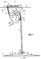
- FIG. 4 shows a floating support 1 of the FPSO type anchored on a drum 1b by lines of anchors 1b, said drum being situated beyond the bow of the FPSO and connected to a bottom-surface connection of type hybrid tower 2 comprising 4 flexible pipes 4, 4a-4b and a multi-riser tower 3.
- the said flexible pipes 4 are connected to the top of the tower 3, each flexible pipe 4 being respectively connected to each of the rigid pipes 10 of said tower multi-risers 3, as will be explained in detail further in the description of the invention below.
- Two first flexible pipes 4a, 4a1-4a2 have on a portion 4-3 of their length floats 4-5 which give it a positive buoyancy, thus ensuring a continuity of curvature variation, directed downwards or bottom 5, until at its connection with the upper end 10a of a substantially straight rigid pipe 10 of the tower, the radius of curvature is substantially infinite, that is to say that its curvature is substantially zero.
- the first portion 4-4 of the first flexible pipe 4a between the drum and the part 4-3 is free of floats and therefore has an apparent weight in the water and its overall curvature has a concavity directed upwards in the form of a plunging chain .
- the first portion 4-4 and the end portion 4-3 of first flexible lines 4a are separated by an inflection point 4-6, that is to say a change in the curvature of the pipe 4a, the end portion 4 -3 with positive buoyancy having a curved shape with convexity directed towards the surface 1c.
- the assembly of the first flexible pipe thus has an S configuration.
- Two second flexible pipes 4b, 4b1-4b2 of smaller Each diameter is connected to a connection device of gooseneck type 4c ("gooseneck" in English), the latter being connected to the upper end of a corresponding rigid pipe 10 of the tower 3.
- the curvature of the second flexible pipes 4b is concavity upwards in a plunging chain from its connection point 4-1 with the drum to its connection point 4-2 with the gooseneck 4c.
- the bottom of the tower 3 is connected to a suction anchor type foundation 5a driven into the seabed 5, via a flexible hinge 6a integral with the lower end of the tendon 6 located at the Z axis 1 Z 1 of the tower 3 and taking up all the upward vertical forces created by the various buoyancy elements 11 and 21 integrated in the tower as will be explained further in the detailed description of the invention herein. after.
- variable inertia junction part 6b is much more reliable because there is a single component and therefore no relative movement between several components as is the case for a flexible mechanical joint 6a.
- the latter is very delicate and much more expensive to manufacture to achieve the same level of reliability.
- Such a variable inertia junction part 6b is detailed in the patents WO 2009/138609 and WO 2009/138610 of the plaintiff.
- said tendon 6 and said upper support structure 3a are not suspended from a submerged submerged float.
- said tendon 6 may be located at a distance from the vertical axis of the drum (ZZ) less than the distance between said axis of the drum and the end furthest from said floating support, that is to say at the inside the avoidance zone of the ship and this without risk to the ship.
- a multi-curvature connecting pipe 13 ensures the connection by connectors 8 and 9 between the bent lower end 10c of the pipe 10 and a pipe 12 resting at the bottom of the sea joining the wellheads, known to man art.
- the constitution of the tower 3 proper has been illustrated in side view and partly torn off. It consists of an upper supporting structure forming an upper platform 3a to which are fixed a plurality of rigid pipes 10 extending over the entire height of said tower, each of the upper ends of said pipes comprises a connecting flange 10a extending above the carrier structure 3a so as to be connected respectively to a flange at the end 4-2 of the corresponding first flexible pipe 4a, 4a1-4a2.
- each of the flanges 10a is shifted upwards respectively of increasing values h1 -h2-h3 compared to the platform 3a as illustrated on this figure 3 .
- the values of h1-h2-h3 depend on the type and number of first flexible pipes and are such that the values h3-h2 and h2-h1 are between 2 m and 10 m, preferably 3 to 6 m.
- each of the rigid pipes 10 is surrounded by tubular sleeves 11, preferably made up of semi-cylindrical half-shells 11a assembled together, so as to constitute not only an insulation of the pipe, but also a buoyancy which compensates for the self-weight of the current conduct.
- These sleeves 11 are installed continuously from the top of the rigid pipe, at the level of the upper flange 10a to the foot of the tower 3, at the end of the pipe 10 equipped with the male part of a connector automatic 8a.
- the bent lower portion 10c and the upper portion 10b between the upper platform 3a and the flange 10a of the rigid pipe 10 are also equipped with insulation sleeves and buoyancy, not shown, similar to the sleeves 11 described above.
- Each of the sleeves 11 is mechanically fixed to its rigid pipe 10 rigidly, by means not shown, so that said sleeve does not slide axially on said pipe 10.
- the buoyancy of the sleeve corresponds exactly to the weight in the water of the pipe portion 10 it covers, then every meter of pipe with its sleeve has a zero weight in water.
- the linear buoyancy of all the sleeves 11 corresponds to 102 to 115%, preferably from 103 to 106%, of the weight of the entire pipe 10 immersed in water and filled with water.
- the dead weight of the pipe 10 filled with water is compensated along said pipe 10 and a residual buoyancy then applies on the underside of the upper platform 3a corresponding to 2 to 15%, preferably 3 to 6% of the self weight of the pipe filled with water in the water.
- This buoyancy is transmitted to the upper platform 3a via the pipe 10, integral with said platform 3a.
- said pipe 10 is in a compression state in the upper part close to said upper platform 3a.
- the pipe 10 is filled with hydrocarbon, generally of density 0.8 to 0.9
- the force transmitted to the upper platform 3a increases by the same amount and the portion of line 10 under compressive stress also increases.
- the compression stress in the area near said upper platform 3a also increases in the same proportions.
- the interior of the vertical pipe 10 can be found completely filled with gas, thus empty of hydrocarbon.
- the pipe 10 is then completely light and the upper portion of pipe 10 under compressive stress is then maximum, and the compressive stress in the area near said upper platform 3a is also maximum.
- a portion of 15 to 40% of the length of the vertical rigid pipe 10 may end up, when it is filled with gas, under axial compression stress, which creates a significant risk of lateral buckling (lateral buckling). in English).
- guiding modules 20 consisting of a rigid structure comprising a central element 20b integral with the central tendon 6 and a plurality of guide elements 20a guiding and maintaining the vertical pipes 10 of the turn 3 at a constant distance from the central tendon 6, and thus substantially in a straight line.
- the guide elements 20a are distributed in a plane substantially perpendicular to the axis Z 1 Z 1 of the tower 3, and are arranged all around said central tendon 6, preferably at a constant distance from said central tendon and connected to the element 20 b by arms or structural members 20c, preferably made of steel, the assembly thus constituting a diaphragm for guiding the pipes 10 insulated by the sleeves 11.
- Said guide element 20a forms a tubular orifice, preferably having a circular cross-section, whose inner diameter is slightly greater than the outer diameter of the buoyancy sleeves 11 of the corresponding rigid pipe 10.
- the pipe 10 isolated by the sleeves 11 is free to slide freely over the entire height below the upper platform 3a, under the effects of temperature, pressure or reduction in length due to compression (full driving - empty driving). All these variations in the length of the pipes 10 then reverberate at the low level of the tower and generate movements which are absorbed by said pipes. junction 13 with multiple curvature.
- each of the rigid pipes 10 is suspended from the upper platform 3a, it can extend or retract individually without changing the behavior of the rigid pipes 10 neighbors.
- These guide modules or diaphragms 20 are arranged over the entire height of the tower 3, preferably at constant intervals H, but may advantageously be arranged more closely together in the upper part so as to avoid the phenomena of buckling previously described.
- the guide modules 20 are advantageously spaced 5 to 7.5 m over a height of 150 m from the upper platform 3a, then from 10 m over the next 300 m, and finally from 15 m on the rest of the height, to the foot of the tower.
- the central tendon 6 is itself provided with buoyancy elements or third floats 21 over its entire height.
- buoyancy elements or third floats 21 over its entire height.
- FIG 3 for a better understanding of the figure, there is shown a single floating element 21 between two guiding modules 20.
- the buoyancy of each of the elements 21 is adjusted to compensate for the self weight in the water of the tendon 6 itself, as well as the proportion of corresponding guiding module self weight.
- the buoyancy element 21 as drawn on the figure 3 compensates for the weight in the water of the height H of the tendon 6 as well as the weight in the water of a complete guide module 20.
- the second flexible pipes 4b are lighter than the first pipes 4a and their weight can be taken up by the upper platform 3a. It is the same gooseneck 4c and various structural elements not shown. However, buoyancy elements, not shown, can compensate for the self-weight of all second conduits 4b of said flexible conduits, their respective gooseneck devices and the self weight of said upper platform 3a, all can represent several tens of tons in total.
- the second flexible pipes 4b will be of smaller diameter and lower weight in the water than the first pipes 4a, so as not to unnecessarily increase the additional buoyancy required at the upper platform 3a.
- the first flexible pipes 4a heavier or larger diameter have their own buoyancy 4-5 on a part 4-3 of their length, as explained above.
- the vertical tension exerted on the foundation 5a substantially corresponds to the resultant of the forces directed upwards at the upper platform 3a, therefore to the sum of all the vertical forces directed upwards of each of the rigid pipes 10, which they are full of water, crude oil, or gas, as previously described.
- a mechanical joint 6a that is very delicate and expensive to manufacture has its cost considerably increased because it must be over-sized for extreme efforts that in fact will never occur, but which, on a safety level, are considered to be necessary. the maximum value of the efforts to be taken into account, apart from the usual safety factors.
- ducts 10 Five ducts 10 are thus represented, of which three simple ducts according to the figure 3A and two pipes in piggyback, according to the figure 3C , a small pipe 10-1 being a gas injection pipe in the corresponding large pipe 10, the injection mode, known to those skilled in the art, being performed at the bottom of the tower and serves to accelerate the speed crude oil to the FPSO.
- the Figure 4B is a perspective view of a tower 3 whose cross section corresponds to the Figure 4A illustrating three guiding modules 20 and five ducts 10 equipped with their insulating and buoyant elements or first floats 11.
- These screens 22 are advantageously manufactured in two half-shells and have a length substantially corresponding to the distance H between said two said guide modules 20. They are then assembled directly between two modules 20 and mechanically fixed thereto.
- these screens 22 confine the internal volume 23 between said two guiding modules 20 and said outer casing 22, thus limiting the thermal transfers with the environment 24 and reduce the thermal losses at the insulation sleeves. 11
- the temperature t 1 inside 23 will always be greater than the temperature t 0 outside 24. This results in a differential of lower temperature between the pipes 10 and the inside 23, and therefore significantly reduced heat losses.
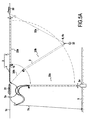
- the figure 6 is a top view of an FPSO 1 anchored on the drum 1a and connected to four hybrid towers 3-1, 3-2, 3-3, 3-4, by a plurality of flexible pipes 4a.
- a fifth multi-riser 3-5 tower has been pre-installed, but will only be connected later when extending the oil field.
- the four rigid pipes 10 are connected on the one hand to the FPSO 1 by four first flexible pipes 4a, and on the other hand, at the bottom of the tower, to four rigid pipes. 12 on the seabed.
- the tower 3-3 On the tower 3-3, only two rigid pipes 10 are connected to the FPSO by two flexible pipes 4a and rigid pipes 12 resting on the bottom, two pipes 10 being waiting for connection to Wellheads, as well as the FPSO.
- the tower 3-4 has only three rigid pipes 10 connected to the FPSO by 3 flexible pipes 4a and rigid pipes 12 resting on the bottom.
- Such a fan installation makes it possible to install at least a portion of the multi-riser towers 3 in the avoidance zone of the floating support 1 in order to increase the number of hybrid type 2 surface-type links and to reduce the length flexible pipes 4.
Description
La présente invention concerne une installation de liaisons fond-surface multiples entre des conduites sous-marines reposant au fond de la mer et un support flottant en surface, comprenant une tour hybride constituées d'une pluralité de conduites flexibles reliées à une pluralité de conduites rigides montantes, ou risers verticaux, dont l'extrémité inférieure de la tour hybride est solidaire d'un dispositif d'ancrage comprenant une embase disposée au fond de la mer.The present invention relates to an installation of multiple bottom-surface connections between submarine pipes resting at the bottom of the sea and a floating support surface, comprising a hybrid tower constituted by a plurality of flexible pipes connected to a plurality of rigid pipes. risers, or risers vertical, the lower end of the hybrid tower is secured to an anchoring device comprising a base disposed at the bottom of the sea.
Le secteur technique de l'invention est plus particulièrement le domaine de la fabrication et de l'installation de colonnes montantes (« riser ») de production pour l'extraction sous-marine de pétrole, de gaz ou autre matériau soluble ou fusible ou d'une suspension de matière minérale à partir de tête de puits immergé jusqu'à un support flottant, pour le développement de champs de production installés en pleine mer au large des côtes. L'application principale et immédiate de l'invention étant dans le domaine de la production pétrolière.The technical field of the invention is more particularly the field of the manufacture and installation of production risers for the underwater extraction of oil, gas or other soluble or fusible material or a suspension of mineral material from wellhead immersed to a floating support, for the development of production fields installed offshore at sea. The main and immediate application of the invention being in the field of oil production.
Le support flottant comporte en général des moyens d'ancrage pour rester en position malgré les effets des courants, des vents et de la houle. Il comporte aussi en général des moyens de stockage et de traitement du pétrole ainsi que des moyens de déchargement vers des pétroliers enleveurs, ces derniers se présentant à intervalle régulier pour effectuer l'enlèvement de la production. L'appellation courante de ces supports flottants est le terme anglo-saxon "Floating Production Storage Offloading" (signifiant "moyen flottant de stockage, de production et de déchargement") dont on utilise le terme abrégé "FPSO" dans l'ensemble de la description suivante.The floating support generally comprises anchoring means to remain in position despite the effects of currents, winds and waves. It also generally comprises oil storage and processing means as well as means of unloading to removal tankers, the latter being present at regular intervals to carry out the removal of the production. The common name of these floating supports is the Anglo-Saxon term "Floating Production Storage Offloading" (meaning "floating medium of storage, production and unloading") which one uses the abbreviated term "FPSO" in the whole of the following description.
Les supports flottants sont :
- soit du type à cap fixe, c'est-à-dire qu'ils possèdent une pluralité d'ancres, en général situées à chacun des angles dudit support flottant maintenant ce dernier dans un cap fixe et n'autorisant alors que le roulis le tangage et limitant les embardées et le lacet ;
- soit du type à touret, c'est-à-dire que toutes les ancres convergent vers une structure cylindrique solidaire du navire, mais libre en rotation selon l'axe vertical ZZ, le support flottant étant alors libre de tourner autour dudit touret et se positionner dans la direction de moindre effort de la résultante des effets du vent, du courant et de la houle sur le support flottant et ses superstructures.
- either of the fixed heading type, that is to say that they have a plurality of anchors, generally located at each of the angles of said floating support now the latter in a fixed heading and then allowing only roll pitching and limiting yaw and yaw;
- either of the reel type, that is to say that all anchors converge to a cylindrical structure integral with the ship, but free to rotate along the vertical axis ZZ, the floating support then being free to turn around said reel and position in the direction of least effort of the resultant effects of wind, current and swell on the floating support and its superstructures.
Le support flottant est donc soit ancré à ses quatre coins et il garde alors un cap sensiblement constant pendant toute la durée de vie des installations, soit il est ancré en un seul point, appelé touret, situé en général vers l'avant du navire, en général dans le tiers avant, ou encore à l'extérieur du navire à quelques mètres de la proue du navire. Le FPSO tourne alors autour de son touret et se positionne naturellement dans la direction de moindre résistance par rapport aux forces créées par la houle, le vent et le courant. Les liaisons fond-surface sont reliées à la partie interne du touret sensiblement fixe par rapport au sol et des joints tournants, connus de l'homme de l'art, transfèrent vers le FPSO les fluides, la puissance électrique ou les signaux électriques entre lesdites liaisons fond-surface et ledit FPSO. Ainsi, dans le cas d'un FPSO sur touret, ce dernier peut tourner sur 360° autour de l'axe de son touret qui reste sensiblement fixe par rapport au sol.The floating support is either anchored at its four corners and it then keeps a substantially constant course throughout the lifetime of the facilities, or it is anchored in a single point, called reel, usually located towards the front of the ship, usually in the front third, or outside the ship a few meters from the bow of the ship. The FPSO then turns around its reel and naturally positions itself in the direction of least resistance compared to the forces created by the swell, the wind and the current. The bottom-surface connections are connected to the inner portion of the drum substantially fixed relative to the ground and rotary joints, known to those skilled in the art, transfer to the FPSO fluids, electrical power or electrical signals between said bottom-surface bonds and said FPSO. Thus, in the case of an FPSO on a drum, it can rotate 360 ° around the axis of its drum which remains substantially fixed with respect to the ground.
Lorsque les conditions sont sévères, voire extrêmes comme en Mer du Nord, un support flottant avantageux est du type à touret dans lequel toutes les liaisons fond-surface doivent converger vers un touret avant de rejoindre le FPSO proprement dit, par l'intermédiaire d'un raccord à joint tournant situé à l'axe dudit touret. En général, les conduites de liaisons fond-surface sont réalisées par des conduites flexibles reliant directement les conduites reposant sur le fond de la mer au touret, lesdites conduites flexibles étant en général organisées radialement ou en étoile uniformément réparties tout autour de l'axe dudit touret. Ce type de liaison fond-surface est plus particulièrement destiné aux profondeurs de 200 à 750 m.When the conditions are severe or even extreme as in the North Sea, an advantageous floating support is of the reel type in which all the bottom-surface links must converge towards a reel before joining the FPSO proper, via a rotary joint fitting located at the axis of said reel. In general, the bottom-surface connection pipes are made by flexible pipes directly connecting the pipes resting on the bottom of the sea to the drum, said flexible pipes being generally organized radially or star uniformly distributed all around the axis of said reel. This type of bottom-surface connection is more particularly intended for the depths of 200 to 750 m.
La présente invention concerne plus particulièrement une installation de liaison fond-surface entre une pluralité de conduites sous-marine reposant au fond de la mer et un support flottant en surface, comprenant une tour hybride constituée d'une pluralité de conduites flexibles reliées à des conduites rigides montantes, ou risers verticaux, l'extrémité supérieure desdites conduites flexibles étant solidaire d'un touret pivotant librement à l'avant du navire ou au sein du navire, en général dans le tiers avant dudit navire.The present invention relates more particularly to a bottom-to-surface connection facility between a plurality of underwater pipes resting at the bottom of the sea and a surface floating support, comprising a hybrid tower consisting of a plurality of flexible pipes connected to pipes. rigid risers, or vertical risers, the upper end of said flexible pipes being secured to a drum freely pivoting to the front of the ship or within the ship, usually in the forward third of said vessel.
Il existe une grande variété de liaisons fond-surface permettant de relier des têtes de puits sous-marines à un support flottant de type FPSO et dans certains développements de champs, on relie plusieurs têtes de puits en parallèle à une même liaison fond-surface de manière à limiter le nombre de conduites reliées au touret du FPSO, ce qui simplifie la conception du touret, ce dernier étant alors principalement conçu pour reprendre les efforts d'ancrage du FPSO soumis aux effets de la houle, du vent et des courants.There is a wide variety of bottom-to-surface bonds for connecting underwater wellheads to an FPSO floating support, and in some field developments, several wellheads are connected in parallel to a single bottom-to-surface bond. in order to limit the number of pipes connected to the FPSO drum, which simplifies the design of the drum, the latter being then mainly designed to resume the anchoring efforts of the FPSO subjected to the effects of waves, wind and currents.
De nombreuses configurations ont été développées et l'on connaît le brevet
- un riser vertical dont l'extrémité inférieure est ancrée au fond de la mer par le biais d'une articulation flexible, et relié à une dite conduite reposant au fond de la mer, et l'extrémité supérieure est tendue par un flotteur immergé en subsurface auquel elle est reliée, et
- une conduite de liaison flexible, entre l'extrémité supérieure dudit riser et un support flottant en surface, ladite conduite de liaison flexible prenant, le cas échéant, de par son propre poids la forme d'une courbe en chaînette plongeante, c'est-à-dire descendant largement en dessous du flotteur pour remonter ensuite jusqu'audit support flottant, laquelle chaînette plongeante autorise des déplacements importants du support flottant absorbés par les déformations de la conduite flexible, notamment la montée ou la descente dudit point bas d'inflexion de la chaînette plongeante.
- a vertical riser whose lower end is anchored to the seabed by means of a flexible hinge, and connected to a said pipe resting at the bottom of the sea, and the upper end is stretched by a float immersed in the subsurface to which it is connected, and
- a flexible connecting pipe, between the upper end of said riser and a floating support surface, said flexible connecting pipe taking, if appropriate, by its own weight in the form of a plunging chain curve, that is, that is to say, descending widely below the float and then up to said floating support, which plunger chain allows large displacements of the floating support absorbed by the deformations of the flexible pipe, including the rise or fall of said low point of inflection of the plunging chain.
On rappelle que la fonction essentielle des conduites flexibles plongeantes est d'absorber au moins en partie les mouvements des extrémités supérieures de conduites rigides auxquelles une de leurs extrémités est reliée et/ou les mouvements de support flottant auquel leur autre extrémité est reliée en découplant mécaniquement les mouvements respectifs des extrémités supérieures de conduites rigides auxquelles elles sont reliées et des supports flottants auxquels elles sont également reliées à leur autre extrémité.It is recalled that the essential function of the plunging flexible pipes is to absorb at least in part the movements of the upper ends of rigid pipes to which one of their ends is connected and / or floating support movements to which their other end is connected by mechanically uncoupling the respective movements of the upper ends of rigid pipes to which they are connected and floating supports to which they are also connected at their other end.
De façon connue, une dite conduite de liaison flexible prend de par son propre poids la forme d'une courbe en chaînette plongeante, c'est-à-dire descendant largement en dessous de ses points d'accroche à chaque extrémité avec respectivement le support flottant et l'extrémité supérieure de la conduite rigide à laquelle elle est reliée, pour autant que la longueur de ladite conduite flexible soit supérieure à la distance entre son point d'accroche au support flottant et l'extrémité supérieure de ladite conduite rigide à laquelle elle est reliée.In known manner, a so-called flexible connecting pipe takes its own weight in the form of a plunging chain curve, that is to say falling well below its attachment points at each end with the support respectively. floating and the upper end of the rigid pipe to which it is connected, provided that the length of said flexible pipe is greater than the distance between its point of attachment to the floating support and the upper end of said rigid pipe to which she is connected.
Pour relier les conduites flexibles auxdites conduite rigide ou riser on intercale des dispositifs de type col de cygne connu de l'homme de l'art et dont un exemple amélioré est décrit dans
Mais, dès que la profondeur d'eau atteint 1 000 - 1 500 m, voire 2 000 - 3 000 m, le coût de cette multiplicité de conduites flexibles devient très élevé en raison de la longueur développée de chacune desdites conduites flexibles, car ces conduites flexibles sont très complexes et très délicates à fabriquer pour atteindre des niveaux de sûreté de fonctionnement requis pour rester en opération sur des durées pouvant atteindre et dépasser 20-25 ans, voire plus. En particulier, les conduites flexibles risquent d'interférer entre elles et s'entrechoquer.But, as soon as the water depth reaches 1,000 - 1,500 m or even 2,000 - 3,000 m, the cost of this multiplicity of flexible pipes becomes very high because of the developed length of each of said flexible pipes, because these Flexible pipes are very complex and very delicate to manufacture to achieve the levels of dependability required to remain in operation for periods of up to and over 20-25 years or more. In particular, the flexible pipes may interfere with each other and clash.
Dans
Dans
D'autre part, la structure de guidage permet de garantir que la courbure desdites chaînettes plongeantes au niveau de leur point bas d'inflexion reste toujours avec un rayon de courbure supérieur à un rayon de courbure minimal en deçà duquel la déformation de la conduite flexible deviendrait irréversible et/ou l'endommagerait.On the other hand, the guiding structure makes it possible to guarantee that the curvature of said plunger chains at their inflexion low point always remains with a radius of curvature greater than a minimum radius of curvature below which the deformation of the flexible duct would become irreversible and / or damage it.
Au total, ladite structure de guidage de
Toutefois, dans certains développements de champs, on est obligé de relier chacune des tête de puits individuellement au dit FPSO et on se retrouve alors avec une très grande quantité de liaisons fond-surface, ce qui nécessite d'augmenter les dimensions du touret et/ou la structure de guidage telle que décrite dans
Un but de la présente invention est donc de fournir une installation apte à comprendre un plus grand nombre de liaison fond-surface reliant un touret et des conduites au fond de la mer dans un encombrement réduit et des conditions de fiabilité mécanique et de coût tout aussi optimales.An object of the present invention is therefore to provide an installation capable of including a greater number of bottom-surface connection connecting a drum and pipes at the bottom of the sea in a small footprint and conditions of mechanical reliability and cost just as optimal.
Pour mettre en oeuvre un maximum de liaisons fond-surface à partir d'un même support flottant afin d'optimiser l'exploitation des champs pétroliers, on a proposé différents systèmes pouvant associer plusieurs risers verticaux ensemble afin de réduire l'encombrement du champ d'exploitation et pouvoir mettre en oeuvre un plus grand nombre de liaisons fond-surface reliés à un même support flottant. Typiquement il est nécessaire de pouvoir installer jusqu'à 30, voire 40 liaisons fond-surface à partir d'un même support flottant.To implement a maximum of bottom-surface connections from the same floating support in order to optimize the exploitation of oil fields, various systems have been proposed that can combine several vertical risers together in order to reduce the bulk of the field. exploitation and be able to implement a greater number of bottom-surface links connected to the same floating support. Typically it is necessary to be able to install up to 30 or even 40 bottom-surface bonds from the same floating support.
Dans
La liaison avec la conduite sous-marine reposant sur le fond de la mer est en général effectuée par une portion de conduite en forme de queue de cochon ou en forme de S, appelée « jumper » ledit S étant alors réalisé dans un plan soit vertical soit horizontal, la liaison avec ladite conduite sous-marine étant en général réalisée par l'intermédiaire d'un connecteur automatique.The connection with the submarine pipe resting on the sea floor is generally carried out by a portion of pipe shaped pig or S-shaped, called "jumper" said S then being made in a plane is vertical is horizontal, the connection with said underwater pipe is generally performed via an automatic connector.
Pour mettre en oeuvre des tours hybrides multi-risers telles que décrites dans
Par ailleurs, dans
Dans
- a) un tendon vertical solidaire à son extrémité supérieure d'une structure porteuse apte à être suspendue à un flotteur au sommet immergé en subsurface, par l'intermédiaire d'une chaine ou câble, ledit tendon étant solidaire à son extrémité inférieure à une structure inférieure de guidage et étant apte à être fixé à une embase reposant au fond de la mer ou une fondation enfoncée au fond de la mer, de préférence par l'intermédiaire d'une articulation flexible, et
- b) une pluralité de conduite rigide verticale dénommé riser dont l'extrémité supérieure est solidaire de ladite structure porteuse, l'extrémité inférieure de chaque dite conduite rigide ou riser étant apte à être reliée à une conduite sous-marine reposant au fond de la mer,
- c) une pluralité de moyens de guidage desdits risers, lesdits moyens de guidage ainsi que ladite structure inférieure de guidage étant aptes à maintenir lesdits risers disposés autour dudit tendon, et
- d) des éléments de flottabilité coopérant avec ledit tendon, répartis le long dudit tendon, de préférence des éléments de flottabilité résistants à la pression hydrostatique sous-marine, de préférence encore des éléments de flottabilité en mousse syntactique, et
- a) a vertical tendon secured at its upper end to a supporting structure capable of being suspended from a submerged submerged top float, via a chain or cable, said tendon being integral at its lower end with a structure lower guide and being adapted to be fixed to a base resting at the bottom of the sea or a foundation sunk to the bottom of the sea, preferably via a flexible joint, and
- b) a plurality of rigid vertical pipe called riser whose upper end is integral with said support structure, the lower end of each said rigid pipe or riser being adapted to be connected to a subsea pipe resting at the bottom of the sea ,
- c) a plurality of means for guiding said risers, said guide means and said lower guide structure being able to hold said risers arranged around said tendon, and
- d) buoyancy elements cooperating with said tendon, distributed along said tendon, preferably buoyancy elements resistant to the underwater hydrostatic pressure, more preferably syntactic foam buoyancy elements, and
Lesdits modules et donc lesdits éléments de flottabilité coulissent le long du tendon en dessous de ladite structure porteuse et sont retenus à l'extrémité supérieure desdits risers et tendon par ladite structure porteuse. La tension créée par la somme des flottabilités des différents modules est ainsi transférée au sommet du tendon par l'intermédiaire de ladite structure porteuse contre laquelle vient bien buter le module de flottabilité supérieur, les autres modules étant plaqués les uns dessous et contre les autres.Said modules and therefore said buoyancy elements slide along the tendon below said carrier structure and are retained at the upper end of said risers and tendon by said carrier structure. The tension created by the sum of the buoyancy of the different modules is thus transferred to the top of the tendon by means of the said supporting structure against which the upper buoyancy module abuts, the other modules being pressed against each other and against the others.
Ainsi, dans ce mode de réalisation, du fait que les modules de flottabilité coulissent sur les risers et tendon, toute la tension est ramenée au niveau de la structure porteuse supérieure à laquelle sont fixés les extrémités supérieures des risers et la structure des modules ainsi que la liaison entre les risers et la structure porteuse supérieure doit reprendre des efforts de traction considérables représentant tout le poids des risers. En effet, si la fondation n'est soumise qu'à la force résultante TR s'exerçant au niveau du flotteur de tête, à savoir 10 à 50% du poids total de la tour, le poids total de la tour est repris directement par l'ensemble des modules de flottabilité, ces derniers exerçant une poussée verticale vers le haut directement sur la sous-face de ladite structure porteuse. Plus particulièrement, l'ensemble des modules de flottabilité apportent une flottabilité cumulée ΣF représentant une force de traction d'intensité supérieure au poids total de la tour Pt, de préférence de 102 à 110% du poids total de la tour.Thus, in this embodiment, because the buoyancy modules slide on the risers and tendon, all the tension is reduced to the level of the upper supporting structure to which are fixed the upper ends of the risers and the structure of the modules as well as the connection between the risers and the upper supporting structure must take up considerable tensile forces representing all the weight of the risers. Indeed, if the foundation is subjected only to the resultant force T R exerted at the head float, namely 10 to 50% of the total weight of the tower, the total weight of the tower is taken directly by all the buoyancy modules, the latter exerting a vertical thrust upward directly on the underside of said carrier structure. More particularly, all of the buoyancy modules provide cumulative buoyancy ΣF representing a traction force of intensity greater than the total weight of the tower Pt, preferably from 102 to 110% of the total weight of the tower.
En outre, le pétrole brut cheminant sur de très grandes distances, plusieurs kilomètres, on doit leur fournir un niveau d'isolation extrême et très coûteux pour, d'une part minimiser l'augmentation de viscosité qui conduirait à une réduction de la production horaire des puits, et d'autre part d'éviter le blocage du flot par dépôt de paraffine, ou formation d'hydrates de gaz dès lors que la température descend aux alentours de 30-40°C. Ces derniers phénomènes sont d'autant plus critiques, particulièrement en Afrique de l'Ouest, que la température du fond de la mer est de l'ordre de 4°C et que les pétroles bruts sont de type paraffinique. Il est donc souhaitable que les liaisons fond-surface soient de longueurs réduites et donc que l'encombrement des différentes liaisons reliées à un même support flottant soient limités, pour cette raison supplémentaire d'isolation thermique.In addition, since crude oil travels a great distance over several kilometers, it must be provided with an extreme and very costly level of insulation to, on the one hand, minimize the increase in viscosity which would lead to a reduction in hourly production. wells, and secondly to avoid the blockage of the flow by deposition of paraffin, or formation of gas hydrates when the temperature drops to around 30-40 ° C. These last phenomena are all the more critical, especially in West Africa, the temperature of the seabed is of the order of 4 ° C and the crude oils are paraffinic type. It is therefore desirable for the bottom-surface connections to be of short lengths and thus for the bulk of the various connections connected to the same floating support to be limited, for this additional reason of thermal insulation.
Dans
Un but de la présente invention est donc de fournir une nouveau type d'installation d'une grande quantité de liaisons fond-surface multiples et de types divers en liaison avec un FPSO ancré sur touret, permettant de relier de préférence individuellement une pluralité de têtes de puits et d'installations sous-marines installées au fond de la mer à grande profondeur, c'est-à-dire au-delà de 1 000 m de profondeur d'eau, et ne comportant pas d'élément de flottabilité dangereux, tel un flotteur de tensionnement de grandes dimensions pouvant atteindre 500-1000 m3, voire plus, et surmontant les inconvénients des réalisations antérieures notamment telles que décrites dans
On cherche aussi à fournir une installation apte à exploiter depuis un même support flottant une pluralité de liaisons fond-surface de type tour-hybride d'encombrement et mouvement réduits et qui soit aussi plus simple à installer. Plus particulièrement encore, un autre problème posé selon la présente invention est donc de fournir une installation avec une multiplicité de liaisons fond-surface à partir d'un même support flottant, dont les procédés de pose et de mise en place de l'installation permettent à la fois :
- de réduire la distance d'implantation entre les différentes liaisons fond-surface, c'est-à-dire permettent d'installer une pluralité de liaisons fond-surface dans un espace le plus réduit possible ou en d'autres termes avec une emprise au sol réduite, ceci afin, entre autre, d'augmenter le nombre de liaisons fond-surface qu'il est possible d'installer sur le touret d'un FPSO, sans que lesdites liaisons fond-surface n'interfèrent entre elles, et,
- une fabrication et mise en place aisée par fabrication à terre, puis remorquage sur site et installation définitive après cabanage
- d'optimiser la mise en place des colonnes montantes, le cas échéant équipées des diverses liaisons flexibles, l'ensemble restant en attente de l'installation future du FPSO ancré sur son touret.
- to reduce the implantation distance between the different bottom-surface connections, that is to say make it possible to install a plurality of bottom-surface connections in as small a space as possible or in other words with a right-of-way reduced soil, this in order, among other things, to increase the number of bottom-surface connections that it is possible to install on the drum of an FPSO, without said bottom-surface links interfering with each other, and,
- easy manufacturing and installation by onshore manufacturing, then on-site towing and final installation after cabanage
- to optimize the installation of the risers, possibly equipped with the various flexible links, all remaining pending the future installation of the FPSO anchored on its drum.
En effet, lors de la phase d'ingénierie du développement d'un champ pétrolifère, le réservoir de pétrole n'est connu à ce stade que de manière incomplète, la production à plein régime impose alors bien souvent de reconsidérer, au bout de quelques années, les schémas initiaux de production et l'organisation des équipements associés. Ainsi, lors de l'installation du système initial, le nombre de liaisons fond-surface et leur organisation est défini par rapport à des besoins estimés, lesdits besoins étant de manière quasi-systématique revus à la hausse après la mise en production du champ, soit pour la récupération du pétrole brut, soit pour la nécessité d'injecter davantage d'eau dans le réservoir, soit encore pour récupérer ou réinjecter davantage de gaz. Au fur et à mesure de l'épuisement du réservoir, on est en général amené à forer de nouveaux puits pour réinjecter de l'eau ou du gaz, ou encore à forer des puits de production en de nouveaux endroits du champ, de manière à augmenter le taux de récupération global, ce qui complique d'autant l'ensemble des liaisons fond-surface reliées au touret du FPSO.Indeed, during the engineering phase of the development of an oil field, the oil reservoir is known at this stage only incompletely, production at full speed then often requires reconsideration, after a few months. years, the initial production plans and the organization of associated equipment. Thus, during the installation of the initial system, the number of bottom-surface links and their organization is defined in relation to estimated needs, said needs being almost systematically revised upwards after the bringing the field into production, either for the recovery of crude oil, or for the need to inject more water into the reservoir, or to recover or reinject more gas. As the reservoir is depleted, it is generally necessary to drill new wells to reinject water or gas, or to drill production wells in new areas of the field, so that increase the overall recovery rate, which complicates all the bottom-surface links connected to the FPSO drum.
Un autre problème posé selon la présente invention est de pouvoir réaliser et installer de telles liaisons fond-surface pour conduites sous-marines à grandes profondeurs, telles qu'au-delà de 1 000 mètres par exemple, et de type comportant une tour hybride verticale et dont le fluide transporté doit être maintenu au-dessus d'une température minimale jusqu'à son arrivée en surface, en réduisant au minimum les composants sujets à déperdition thermique, en évitant les inconvénients créés par l'expansion thermique propre, ou différentielle, des divers composants de ladite tour, de manière à résister aux contraintes extrêmes et aux phénomènes de fatigue cumulée sur la durée de vie de l'ouvrage, qui dépasse couramment 20 années.Another problem posed according to the present invention is to be able to make and install such bottom-surface connections for submarine pipes at great depths, such as above 1,000 meters for example, and of type comprising a vertical hybrid tower. and whose transported fluid must be maintained above a minimum temperature until it reaches the surface, minimizing the components subject to heat loss, avoiding the disadvantages created by the clean thermal expansion, or differential, various components of said tower, so as to withstand extreme stresses and cumulative fatigue phenomena over the life of the structure, which currently exceeds 20 years.
Un autre problème de la présente invention est aussi de fournir une installation de liaisons fond-surface multiples avec des tours hybrides dont le système d'ancrage soit d'une grande résistance et d'un faible coût, et dont les procédés de fabrication et mise en place des différents éléments constitutifs soient simplifié et également d'un faible coût, et puisse être réalisé en mer avec des navires d'installation courants.Another problem of the present invention is also to provide a facility of multiple bottom-surface connections with hybrid towers whose anchoring system is of high strength and low cost, and whose manufacturing processes and implementation In place of the various constituent elements are simplified and also of low cost, and can be realized at sea with current installation vessels.
Pour ce faire, la présente invention fournit une installation de liaison fond-surface entre une pluralité de conduites sous-marines reposant au fond de la mer et un support flottant en surface et ancré au fond de la mer, comprenant :
- un dit support flottant comprenant un touret, et
- au moins une tour du type hybride comprenant :
- a) une tour multi-risers comprenant :
- a.1) un tendon vertical solidaire à son extrémité supérieure d'une structure porteuse supérieure, ledit tendon étant fixé à son extrémité inférieure à une embase reposant au fond de la mer ou une ancre, de préférence du type ancre à succion, enfoncée au fond de la mer, et
- a.2) une pluralité de conduites rigides verticales dénommées risers, l'extrémité supérieure de chaque riser étant solidaire de ladite structure porteuse, l'extrémité inférieure de chaque dit riser étant reliée ou apte à être reliée à une conduite sous-marine reposant au fond de la mer,
- a.3) une pluralité de moyens de guidage desdits risers aptes à maintenir lesdits risers disposés autour dudit tendon à une distance sensiblement constante, de préférence régulièrement et symétriquement répartis autour dudit tendon, et
- b) une pluralité de conduites flexibles s'étendant depuis ledit touret jusqu'aux extrémités supérieures d'une respectivement pluralité de conduites rigides, dont au moins une conduite flexible, ci-après dénommée première conduite flexible, comprend une partie terminale de la conduite flexible, du côté de sa jonction à l'extrémité supérieure dudit riser, équipée de flotteurs dénommés premier flotteur lui conférant une flottabilité positive, et au moins la partie supérieure dudit riser vertical est équipée de flotteurs dénommés deuxièmes flotteurs lui conférant une flottabilité positive, de sorte que les flottabilités positives de ladite partie terminale de la première conduite flexible et de ladite partie supérieure dudit riser vertical permettent le tensionnement desdits risers en position sensiblement verticale et l'alignement ou la continuité de courbure entre de l'extrémité de ladite partie terminale à flottabilité positive de ladite première conduite flexible et la partie supérieure dudit riser vertical au niveau de leur raccordement,
- a) une tour multi-risers comprenant :
- au moins deux dites premières conduites flexibles à flottabilité positive dont les extrémités sont fixées respectivement à deux extrémités supérieures de deux dits risers, les deux extrémités supérieures des deux risers arrivant au-dessus de ladite structure porteuse supérieure à des hauteurs différentes, de sorte que lesdites premières conduites flexibles soient positionnées à des hauteurs différentes les unes par rapport aux autres, et
- desdits risers équipés de deuxièmes flotteurs coaxiaux périphériques entourant lesdits risers et solidaires desdits risers, lesdits deuxièmes flotteurs coaxiaux étant répartis, de préférence continument, sur au moins une partie supérieure d'au moins 25% de la longueur desdits risers au-dessous et à partir de ladite structure porteuse supérieure, de préférence une longueur d'au moins 50% de la longueur desdits risers, de préférence encore sur au moins 75% de leur longueur, l'ensemble desdits deuxièmes flotteurs coaxiaux compensant au moins le poids total desdits risers, et
- lesdits modules de guidage solidaires dudit tendon et aptes à coulisser le long desdits deuxièmes flotteurs desdits risers, lesdits modules de guidage étant espacés et répartis, de préférence régulièrement, sur au moins une partie supérieure d'au moins 25% de la longueur dudit tendon au-dessous et à partir de ladite structure porteuse supérieure, de préférence sur une longueur d'au moins 50% de la longueur dudit tendon, de préférence encore sur au moins 75% de sa longueur,
- ledit tendon et ladite structure porteuse supérieure n'étant pas suspendus à un flotteur immergé en subsurface, et ledit tendon étant situé à une distance de l'axe vertical du touret (ZZ) inférieure à la distance entre l'axe dudit touret et l'extrémité la plus éloignée dudit support flottant.
- a said floating support comprising a drum, and
- at least one tower of the hybrid type comprising:
- a) a multi-riser tower comprising:
- a.1) a vertical tendon secured at its upper end to an upper supporting structure, said tendon being fixed at its lower end to a base resting at the bottom of the sea or an anchor, preferably of the suction anchor type, driven into the bottom of the sea, and
- a.2) a plurality of vertical rigid pipes called risers, the upper end of each riser being integral with said supporting structure, the lower end of each said riser being connected or able to be connected to a submarine pipe resting at bottom of the sea,
- a.3) a plurality of means for guiding said risers able to maintain said risers arranged around said tendon at a substantially constant distance, preferably regularly and symmetrically distributed around said tendon, and
- b) a plurality of flexible pipes extending from said drum to the upper ends of a plurality of rigid pipes respectively, of which at least one flexible pipe, hereinafter referred to as the first flexible pipe, comprises an end portion of the flexible pipe , on the side of its junction at the upper end of said riser, equipped with floats called first float giving it a positive buoyancy, and at least the upper part of said vertical riser is equipped with floats called second floats conferring positive buoyancy, so that the positive buoyancy of said end portion of the first flexible pipe and said upper portion of said vertical riser allow the tensioning of said risers in substantially vertical position and the alignment or continuity of curvature between the end of said buoyant end portion; positive of said first c flexible corrugation and the upper part of said vertical riser at their connection,
- a) a multi-riser tower comprising:
- at least two said first positive buoyant flexible pipes whose ends are respectively fixed at two ends upper two of said risers, the two upper ends of the two risers arriving above said upper support structure at different heights, so that said first flexible pipes are positioned at different heights relative to each other, and
- said risers equipped with second peripheral coaxial floats surrounding said risers and integral with said risers, said second coaxial floats being distributed, preferably continuously, over at least an upper portion of at least 25% of the length of said risers below and from of said upper carrier structure, preferably at least 50% of the length of said risers, preferably at least 75% of their length, all of said second coaxial floats compensating for at least the total weight of said risers, and
- said guide modules secured to said tendon and slidable along said second floats of said risers, said guide modules being spaced apart and distributed, preferably regularly, over at least an upper portion of at least 25% of the length of said tendon at said below and from said upper supporting structure, preferably over a length of at least 50% of the length of said tendon, more preferably over at least 75% of its length,
- said tendon and said upper support structure not being suspended from a submerged submerged float, and said tendon being located at a distance from the vertical axis of the reel (ZZ) less than the distance between the axis of said reel and the end furthest from said floating support.
Lesdits moyens de guidage sont avantageusement installés sur toute la hauteur de la tour et ont ainsi pour fonction essentielle de maintenir une géométrie constante de positionnement des risers les uns par rapport aux autres et aux tendons, et ainsi d'empêcher le flambage desdits risers lorsque ceux-ci sont mis en compression, notamment lorsqu'ils sont remplis de gaz, l'espacement entre deux moyens de guidage successifs étant de préférence réduit dans cette zone sujette à flambage latéral.Said guide means are advantageously installed over the entire height of the tower and thus have the essential function of maintaining a constant geometry of positioning the risers with respect to each other and tendons, and thus to prevent the buckling of said risers when those these are put into compression, especially when they are filled with gas, the spacing between two means of successive guidance being preferably reduced in this area subject to lateral buckling.
Du fait de la disposition respective desdites conduites flexibles à flottabilité positive les unes par rapport aux autres, il est possible de mettre en oeuvre sur chaque tour hybride multi-riser une pluralité de conduites flexibles à flottabilité positive, notamment de 2 à 8 conduites flexibles à flottabilité positive, décalées en hauteur bien que rapprochées en terme d'espacement latérale, puisque toutes convergent vers la même tour, c'est-à-dire à proximité du même tendon.Due to the respective arrangement of said flexible pipes with positive buoyancy relative to each other, it is possible to implement on each hybrid multi-riser tower a plurality of flexible pipes with positive buoyancy, in particular from 2 to 8 flexible pipes with positive buoyancy, shifted in height although close in terms of lateral spacing, since all converge towards the same tower, that is to say near the same tendon.
Du fait de la pluralité de conduites flexibles à flottabilité positive en combinaison avec une flottabilité positive répartie sur une dite partie supérieure de la longueur desdits risers et de la longueur dudit tendon à partir de ladite structure porteuse supérieure, il n'est plus nécessaire de mettre en oeuvre un flotteur en tête de la tour pour assurer le tensionnement de la tour. Ainsi il est possible de rapprocher les tours hybrides à l'intérieur de la zone d'évitement du navire sans risque d'accident, comme explicité précédemment. Et, il est ainsi possible de réduire les problèmes liés à la longueur des conduites flexibles, ce qui en réduit le coût de fabrication et d'isolation thermique.Because of the plurality of positive buoyant flexible pipes in combination with positive buoyancy distributed over a said upper portion of the length of said risers and the length of said tendon from said upper support structure, it is no longer necessary to implement a float at the head of the tower to ensure tensioning of the tower. Thus it is possible to bring the hybrid towers within the avoidance zone of the ship without risk of accident, as explained above. And, it is possible to reduce the problems related to the length of flexible pipes, which reduces the cost of manufacturing and thermal insulation.
Du fait que l'ensemble desdits deuxièmes flotteurs coaxiaux compensent au moins le poids total desdits risers, et plus particulièrement que chacun desdits deuxièmes flotteurs associés à un même riser compense au moins le poids total dudit riser, conférant ainsi audit / auxdits risers une flottabilité positive même lorsque ledit / lesdites risers sont remplis d'eau de mer et que éléments de flottabilité de la tour ne coulissent pas le long desdits risers et dudit tendon, l'installation selon l'invention présente les avantages suivants :
- chacun des risers étant indépendant de ses voisins, les efforts engendrés par la flottabilité dudit riser s'applique seulement sur la structure porteuse supérieure, puis sur le tendon, puis sur la fondation, et
- d'autre part, il est possible de combiner isolation thermique et flottabilité en mettant en oeuvre des éléments de flottabilité réalisés dans un matériau combinant les propriétés de flottabilité et d'isolation thermique, notamment tel que décrit dans
FR 11 52574
- each of the risers being independent of its neighbors, the forces generated by the buoyancy of said riser apply only to the upper bearing structure, then to the tendon, then to the foundation, and
- on the other hand, it is possible to combine thermal insulation and buoyancy by implementing buoyancy elements made of a material combining the buoyancy and thermal insulation properties, especially as described in
FR 11 52574
Un autre avantage d'une installation selon l'invention est qu'il est possible de mettre en oeuvre une pluralité de tours hybrides dont les conduites flexibles sont reliées à un même touret mais décalées angulairement et radialement, de manière à ce que les tours soient disposées en éventail autour dudit touret à des distances identiques ou différentes dudit touret, certaines tours pouvant être seulement partiellement installées et ne pas comporter encore de conduites flexibles ou seulement une partie desdites conduites rigides pouvant être prolongées de dites conduites flexibles à leurs extrémités supérieures et/ou raccordées à desdites conduites sous-marines reposant au fond de la mer à leurs extrémités inférieures, lesdites conduites rigides étant en attente de raccordement à des têtes de puits ainsi qu'au support flottant, comme explicité ci-après.Another advantage of an installation according to the invention is that it is possible to implement a plurality of hybrid towers whose flexible pipes are connected to the same drum but offset angularly and radially, so that the turns are arranged in a fan pattern around said drum at identical or different distances from said drum, certain turns being able to be only partially installed and not yet comprising flexible pipes or only a part of said rigid pipes being able to be extended from said flexible pipes to their upper ends and / or or connected to said underwater pipes resting at the bottom of the sea at their lower ends, said rigid pipes being waiting for connection to wellheads as well as to the floating support, as explained hereinafter.
On entend ici par « première conduite flexible » les conduites connues sous la dénomination « flexible » bien connues de l'homme de l'art et qui ont été décrites dans les documents normatifs publiés par l'American Petroleum Institute (API), plus particulièrement sous les références API 17J et API RP 17 B. De tels flexibles sont notamment fabriqués et commercialisés par la Société TECHNIP France sous la marque COFLEXIP. Ces conduites flexibles comportent en général des couches d'étanchéité internes en matériaux thermoplastiques associées à des couches résistantes à la pression interne à la conduite, en général en acier ou en matériaux composites réalisés sous forme de bandes spiralées, jointives à l'intérieur de la conduite thermoplastique pour résister à la pression interne d'éclatement et complétés par des armatures externes au-dessus de la couche tubulaire thermoplastique également sous forme de bandes spiralées jointives, mais avec un pas plus long, c'est-à-dire un angle d'inclinaison de l'hélice inférieur, notamment de 15° à 55°.Here, the term "first flexible conduit" refers to the conduits known under the name "flexible" well known to those skilled in the art and which have been described in the normative documents published by the American Petroleum Institute (API), more particularly under the API 17J and API RP 17 B references. Such hoses are in particular manufactured and marketed by TECHNIP France under the trade name COFLEXIP. These flexible pipes generally comprise internal sealing layers of thermoplastic materials associated with layers resistant to the pressure internal to the pipe, generally made of steel or composite materials made in the form of spiral strips, contiguous inside the thermoplastic pipe to withstand the bursting internal pressure and supplemented by external reinforcements above the thermoplastic tubular layer also in the form of contiguous spiral strips, but with a pitch longer, that is to say an angle of inclination of the lower helix, in particular from 15 ° to 55 °.
On entend par « vertical » que lorsque la mer est calme et que l'installation est au repos, les flexibles de liaison vers le FPSO n'étant pas installés, le tendon et les risers sont disposés sensiblement verticalement, étant entendu que la houle, et les mouvements du support flottant et/ou des conduites flexibles peuvent provoquer des débattement de la tour dans un angle au sommet de préférence limité à 10-15°, en particulier du fait de la mise en oeuvre d'une pièce de jonction et de transition d'inertie, ou d'une articulation flexible de type Roto-Latch® au pied du tendon, au niveau de son point de fixation à ladite embase ou ancre."Vertical" means that when the sea is calm and the installation is at rest, the connection hoses to the FPSO not being installed, the tendon and the risers are arranged substantially vertically, it being understood that the swell, and the movements of the floating support and / or flexible ducts can cause the tower to travel in a vertex angle preferably limited to 10-15 °, in particular because of the use of a connecting piece and transition of inertia, or a flexible articulation of the Roto-Latch ® type at the foot of the tendon, at its point of attachment to said base or anchor.
On utilise ici le terme tour ou "riser vertical" pour rendre compte de la position théorique sensiblement verticale desdits risers lorsqu'ils sont au repos étant entendu que les axes des risers peuvent connaître des mouvements angulaires par rapport à la verticale et se mouvoir dans un cône d'angle γ dont le sommet correspond au point de fixation de l'extrémité inférieure du tendon sur ladite embase. L'extrémité supérieure d'un dit riser vertical peut être légèrement incurvée. On entend donc par « partie terminale de première conduite flexible sensiblement dans l'alignement de l'axe Z1Z1 dudit riser que l'extrémité de la courbe de chaînette inversée de ladite première conduite flexible est sensiblement tangente à l'extrémité dudit riser vertical. En tout état de cause, en continuité de variation de courbure, c'est-à-dire sans point singulier, au sens mathématique.The term tower or "vertical riser" is used here to account for the substantially vertical theoretical position of said risers when they are at rest, provided that the axes of the risers can know angular movements with respect to the vertical and move in a angle cone γ whose apex corresponds to the attachment point of the lower end of the tendon on said base. The upper end of a vertical riser can be slightly curved. Therefore, the term "first flexible pipe end portion substantially in alignment with the axis Z 1 Z 1 said riser that the end of the inverted chain curve of said first flexible pipe is substantially tangential to the end of said riser vertical. In any case, in continuity of variation of curvature, that is to say without singular point, in the mathematical sense.
On entend par "continuité de courbure" entre l'extrémité supérieure du riser vertical et la partie de la première conduite flexible présentant une flottabilité positive, que ladite variation de courbure ne présente pas de point singulier, tel une variation brusque de l'angle d'inclinaison de sa tangente ou un point d'inflexion.The term "continuity of curvature" between the upper end of the vertical riser and the portion of the first flexible pipe having a positive buoyancy, that said variation of curvature does not present any singular point, such as a sudden variation of the angle d tilt of its tangent or point of inflection.
De préférence, la pente de la courbe formée par la première conduite flexible est telle que l'inclinaison de sa tangente par rapport à l'axe Z1Z1 de la partie supérieure dudit riser vertical augmente continûment et progressivement depuis le point de raccordement entre l'extrémité supérieure du riser vertical et l'extrémité de ladite partie terminale de la première conduite flexible de flottabilité positive, jusqu'au point d'inflexion correspondant à une inversion de courbure entre ladite partie terminale convexe et la première partie concave de la première conduite flexible.Preferably, the slope of the curve formed by the first flexible pipe is such that the inclination of its tangent relative to the axis Z 1 Z 1 of the upper part of said vertical riser increases. continuously and progressively from the point of connection between the upper end of the vertical riser and the end of said end portion of the first flexible positive buoyancy pipe, to the point of inflection corresponding to an inversion of curvature between said end portion convex and the first concave part of the first flexible pipe.
L'installation selon la présente invention permet donc d'éviter le tensionnement du riser vertical par un flotteur en surface ou sub-surface, auquel son extrémité supérieure serait suspendue. Ce type d'installation confère une stabilité accrue en termes de variation angulaire (γ) de l'angle d'excursion de l'extrémité supérieure du riser vertical par rapport à une position théorique de repos vertical, car cette variation angulaire est réduite en pratique à un angle maximal ne dépassant pas 5°, en pratique de l'ordre de 1 à 4° avec l'installation selon l'invention, alors que, dans les modes de réalisation de la technique antérieure, l'excursion angulaire pouvait atteindre 5 à 10°, voire plus.The installation according to the present invention thus makes it possible to avoid the tensioning of the vertical riser by a surface or sub-surface float, at which its upper end would be suspended. This type of installation confers increased stability in terms of angular variation (γ) of the angle of excursion of the upper end of the vertical riser relative to a theoretical position of vertical rest, because this angular variation is reduced in practice. at a maximum angle not exceeding 5 °, in practice of the order of 1 to 4 ° with the installation according to the invention, whereas, in the embodiments of the prior art, the angular excursion could reach 5 at 10 ° or more.
Un autre avantage de la présente invention tient en ce que, du fait de cette faible variation angulaire de l'extrémité supérieure du riser vertical, il est possible de mettre en oeuvre, au niveau de son extrémité inférieure, un encastrement rigide sur une deuxième ou nième embase reposant au fond de la mer, sans avoir recours à une pièce de transition d'inertie de dimension trop importante et donc trop coûteuse. Il est donc possible d'éviter la mise en oeuvre d'une articulation flexible, notamment du type rotule sphérique flexible, pour autant que la jonction entre l'extrémité inférieure du deuxième ou nième riser et ledit encastrement comprenne une pièce de transition d'inertie.Another advantage of the present invention is that, due to this small angular variation of the upper end of the vertical riser, it is possible to implement, at its lower end, a rigid recess on a second or nth base resting at the bottom of the sea, without having recourse to a part of transition of inertia of dimension too important and thus too expensive. It is therefore possible to avoid the use of a flexible hinge, in particular of the flexible spherical ball type, provided that the junction between the lower end of the second or nth riser and said recess comprises an inertial transition piece. .
De même, et de façon connue, on comprend que ladite structure porteuse supérieure assure le maintien à géométrie constante des extrémités supérieures desdits risers et dudit tendon vertical assurant la fixation entre eux à distance constante.Similarly, and in a known manner, it is understood that said upper support structure ensures the maintenance of constant geometry of the upper ends of said risers and said vertical tendon securing them to each other at a constant distance.
De façon connue, ledit touret comprend une cavité au sein d'une structure déportée à l'avant du support flottant ou intégrée dans ou dessous la coque du support flottant, de préférence ladite cavité traversant la coque du support flottant sur toute sa hauteur.In known manner, said drum comprises a cavity within a remote structure at the front of the floating support or integrated in or below the hull of the floating support, preferably said cavity passing through the hull of the floating support over its entire height.
De façon connue encore, ledit tendon vertical est constitué d'un câble ou d'une barre rigide, notamment métallique, ou encore d'une conduite.In a known manner, said vertical tendon consists of a cable or a rigid bar, in particular metal, or a pipe.
De façon connue, ladite partie terminale de première conduite flexible, s'étend sur une partie seulement de la longueur totale de la première conduite flexible de telle sorte que ladite première conduite flexible présente une configuration en S, avec une première portion de première conduite flexible du coté dudit support flottant présentant une courbure concave en forme de chaînette plongeante et ladite partie terminale restante de ladite première conduite flexible présentant une courbure convexe en forme de chaînette inversée de par sa flottabilité positive. On entend ici par « courbure concave » de ladite première portion de première conduite flexible une courbure à concavité tournée vers le haut, et par « courbure convexe » de ladite partie terminale de première conduite flexible une courbure à convexité tournée vers le haut ou concavité tournée vers le bas.In known manner, said first flexible pipe end portion extends over only a portion of the total length of the first flexible pipe so that said first flexible pipe has an S-shaped configuration, with a first portion of a first flexible pipe on the side of said floating support having a concave curvature in the form of a plunging chain and said remaining end portion of said first flexible pipe having a convex curvature in the form of a chain inverted by its positive buoyancy. Here, the term "concave curvature" of said first portion of a first flexible pipe is a curvature with concavity turned upwards, and "convex curvature" of said end portion of a first flexible pipe a curvature with convexity turned upwards or concavity turned down.
On comprend que lesdites premières conduites flexibles positionnées à des hauteurs différentes signifie que deux points de respectivement une première conduite flexible supérieure et une deuxième conduite flexible inférieure, situés dans une même direction verticale, sont toujours situés l'un au-dessus de l'autre, bien qu'un point de la première conduite flexible supérieure puisse se trouver à une hauteur inférieure à un point de la première conduite flexible inférieure, si les deux points des deux premières conduites flexibles supérieure et inférieure ne sont pas alignés verticalement.It is understood that said first flexible pipes positioned at different heights means that two points of respectively a first upper flexible pipe and a second lower flexible pipe, located in the same vertical direction, are always located one above the other , although a point of the first upper flexible pipe may be at a height less than a point of the first lower flexible pipe, if the two points of the first two upper and lower flexible pipes are not aligned vertically.
On comprend aussi que les deux dites premières conduites flexibles sont nécessairement légèrement décalées latéralement puisque leurs extrémités sont reliées d'une part aux extrémités supérieures desdits risers, lesquels sont décalés latéralement au niveau de ladite structure porteuse supérieure d'une part, et leurs points d'attache au touret sont également légèrement décalés latéralement au niveau du touret. En général, le décalage en hauteur est supérieur au décalage latéral entre les deux premières conduites flexibles.It is also understood that the two said first flexible ducts are necessarily slightly laterally offset since their ends are connected firstly to the upper ends of said risers, which are offset laterally at said upper bearing structure on the one hand, and their dots attached to the drum are also slightly laterally offset at the reel. In general, the height offset is greater than the lateral offset between the first two flexible pipes.
En pratique et selon les diamètres des conduites flexibles à flottabilité positive, le décalage en hauteur minimal des extrémités supérieures desdits risers auxquelles lesdites premières conduites flexibles sont fixées et donc la distance minimale en hauteur entre deux dites premières conduites flexibles disposées à des hauteurs différentes est d'au moins 3 m, de préférence de 5 à 10 m.In practice and according to the diameters of the flexible pipes with positive buoyancy, the minimum offset in height of the upper ends of said risers to which said first flexible pipes are fixed and therefore the minimum distance in height between two said first flexible pipes arranged at different heights is at least 3 m, preferably 5 to 10 m.
Plus particulièrement, une dite tour comprend de 2 à 7 conduites rigides et 2 à 5 dites premières conduites flexibles.More particularly, a said tower comprises from 2 to 7 rigid pipes and 2 to 5 said first flexible pipes.
De façon connue, ledit touret comprend une partie interne cylindrique apte à rester sensiblement fixe par rapport au fond de la mer à l'intérieur de ladite cavité lorsque ledit support flottant est entraîné en rotation autour de l'axe vertical (ZZ) de ladite partie interne ou dite cavité du touret, ledit support flottant étant ancré au fond de la mer par des lignes fixées à leurs extrémités supérieures à ladite partie interne cylindrique du touret.In known manner, said drum comprises a cylindrical inner portion adapted to remain substantially fixed with respect to the seabed inside said cavity when said floating support is rotated about the vertical axis (ZZ) of said portion. internal or said cavity of the drum, said floating support being anchored to the bottom of the sea by lines fixed at their upper ends to said cylindrical inner portion of the drum.
De façon connue, les extrémités inférieures de risers sont fixées aux extrémités des conduites sous-marine reposant au fond de la mer de préférence par l'intermédiaire de connecteurs automatiques entre lesdites extrémités inférieures des riser et extrémités des conduites sous-marine, et/ou par l'intermédiaire de manchettes coudées et/ou des conduites de jonction coudées.In a known manner, the lower ends of the risers are attached to the ends of the underwater pipes resting at the bottom of the sea, preferably via automatic connectors between the said lower ends of the risers and the ends of the underwater pipes, and / or by means of angled sleeves and / or angled connecting lines.
Plus particulièrement, une installation selon l'invention comprend des deuxièmes conduites flexibles de plus petits diamètres ou de plus faible poids linéaires que lesdites première conduites flexibles, lesdites deuxièmes conduites flexibles ne comportant pas d'éléments de flottabilité et étant reliées aux extrémités supérieures de dits riser par l'intermédiaire de dispositifs de connexion, de préférence de type col de cygne, lesdites deuxièmes conduites flexibles étant situées dessous lesdites premières conduites flexibles.More particularly, an installation according to the invention comprises second flexible pipes of smaller diameters or of lower linear weight than said first flexible pipes, said second flexible pipes having no buoyancy elements and being connected to the upper ends of said riser via connection devices, preferably gooseneck type, said second flexible pipes being located below said first flexible pipes.
Avantageusement, des éléments de flottabilité peuvent être solidarisés audite pièce de connexion et/ou en sous face de ladite structure porteuse supérieure pour compenser le poids des dites deuxièmes conduites flexibles et des divers accessoires tels les cols de cygne, les éléments de renfort de structure ainsi que les connecteurs automatiques.Advantageously, buoyancy elements can be secured to said connection piece and / or under the face of said upper support structure to compensate for the weight of said second flexible pipes and various accessories such as goosenecks, structural reinforcement elements and than automatic connectors.
Une installation selon l'invention peut aussi comprendre d'autres « conduite souple sous-marine » comme un câble, un ombilical ou une conduite capable d'accepter des déformations importantes sans engendrer des efforts de rappel significatifs, notamment une conduite flexible. En particulier, un ombilical de commande comportera une ou plusieurs conduites hydrauliques et/ou des câbles électriques pour la transmission d'énergie et/ou d'informations.An installation according to the invention may also comprise other "underwater flexible pipe" such as a cable, an umbilical or a pipe capable of accepting significant deformations without generating significant return forces, in particular a flexible pipe. In particular, a control umbilical will comprise one or more hydraulic lines and / or electric cables for transmitting energy and / or information.
Plus particulièrement, ledit tendon est fixé à son extrémité inférieure à une embase ou ancre par l'intermédiaire d'une pièce de jonction et transition d'inertie dont la variation de l'inertie est telle que son inertie augmente progressivement depuis son extrémité supérieure jusqu'à l'extrémité inférieure de ladite pièce de de jonction réalisant l'encastrement de l'extrémité inférieure dudit tendon au niveau de ladite embase ou ancre.More particularly, said tendon is fixed at its lower end to a base or anchor via a junction piece and inertia transition whose variation of inertia is such that its inertia increases gradually from its upper end to at the lower end of said junction piece making the recess of the lower end of said tendon at said base or anchor.
On entend ici par "inertie", le moment d'inertie de ladite pièce de jonction et transition d'inertie par rapport à un axe perpendiculaire à l'axe de ladite pièce de jonction et transition d'inertie, lequel reflète la raideur en flexion dans chacun des plans perpendiculaires à l'axe vertical de symétrie de ladite pièce de jonction et transition d'inertie, ce moment d'inertie étant proportionnel au produit de la section de matière par le carré de son éloignement par rapport au dit axe de ladite pièce de jonction et transition d'inertie.By "inertia" is meant herein the moment of inertia of said junction piece and transition of inertia with respect to an axis perpendicular to the axis of said junction piece and inertia transition, which reflects flexural stiffness. in each of the planes perpendicular to the vertical axis of symmetry of said connecting piece and inertia transition, this moment of inertia being proportional to the product of the section of material by the square of its distance from said axis of said junction piece and transition of inertia.
De façon connue, ladite pièce de jonction et de transition d'inertie présente une forme cylindro-conique, et ladite pièce de jonction est fixée à sa base à un premier pieu tubulaire passant à travers une cavité cylindrique de ladite embase ou ancre de manière à permettre l'encastrement de ladite pièce de jonction dans ladite embase ou ancre.In known manner, said junction and inertia transition piece has a cylindro-conical shape, and said connecting piece is fixed at its base to a first tubular pile passing through a cavity cylindrical said base or anchor so as to allow the embedding of said connecting piece in said base or anchor.
Plus particulièrement, une installation selon l'invention comprend des troisièmes flotteurs solidaires dudit tendon au moins dans les espaces entre lesdits modules de guidage, lesdits troisièmes flotteurs apportant une flottabilité positive compensant au moins le poids dudit tendon.More particularly, an installation according to the invention comprises third floats integral with said tendon at least in the spaces between said guide modules, said third floats providing a positive buoyancy compensating for at least the weight of said tendon.
Plus particulièrement, lesdits modules de guidage constituent une pluralité de structures rigide indépendantes espacés d'au moins 5 m le long d'au moins la partie supérieure dudit tendon, chaque dite structure rigide comprenant une pluralité d'éléments tubulaires de guidage de risers définissant des orifices tubulaires dans lesquels lesdits risers, équipés de dits deuxièmes flotteurs, peuvent coulisser et un élément central de liaison au tendon définissant de préférence un orifice central traversé par ledit tendon et qui lui est solidarisé notamment par soudure.More particularly, said guide modules constitute a plurality of independent rigid structures spaced at least 5 m along at least the upper part of said tendon, each said rigid structure comprising a plurality of tubular guide elements defining risers. tubular orifices in which said risers, equipped with said second floats, can slide and a central tendon connecting element preferably defining a central orifice traversed by said tendon and which is secured thereto in particular by welding.
Plus particulièrement encore, lesdits modules de guidage et lesdits deuxièmes flotteurs s'étendent sur au moins 50% de la longueur de la tour entre ladite structure porteuse au sommet et l'extrémité inférieure du tendon.More particularly, said guide modules and said second floats extend over at least 50% of the length of the tower between said carrier structure at the top and the lower end of the tendon.
Plus particulièrement, lesdits modules de guidage sont espacés de 2 à 20 m, de préférence de 5 à 15 m, et sont au nombre d'au moins 20, de préférence au moins 50 modules de guidage pour une tour d'au moins 1 000 m de hauteur.More particularly, said guide modules are spaced from 2 to 20 m, preferably from 5 to 15 m, and are at least 20, preferably at least 50 guide modules for a tower of at least 1000 m of height.
Plus particulièrement, l'ensemble desdits premiers flotteurs apportent une flottabilité cumulée représentant une force de traction dirigée vers le haut, d'intensité supérieure au poids total desdits risers, de préférence au poids total de la tour, de préférence de 102 à 115%, de préférence de 103 à 106%, du poids total desdits risers, de préférence encore du poids total de la tour.More particularly, all of said first floats provide cumulative buoyancy representing an upward pulling force of greater intensity than the total weight of said risers, preferably to the total weight of the tower, preferably from 102 to 115%, preferably from 103 to 106%, of the total weight of said risers, more preferably the total weight of the tower.
Ainsi, la tension résultante verticale vers le haut au niveau de ladite structure porteuse supérieure étant de 2 à 15% du poids total de la tour, de préférence de 3% à 6% du poids total de la tour.Thus, the resulting vertical upward tension at said upper bearing structure being from 2 to 15% of the total weight of the tower, preferably from 3% to 6% of the total weight of the tower.
Ainsi, ladite tour multi-risers est tensionnée par lesdits flotteurs et ledit support est ancré de manière à ce que l'angle γ entre l'axe (Z1Z1) dudit tendon et la verticale reste inférieur à 10°, lorsque le support flottant est mouvementé de par l'agitation de la mer et/ou la force du vent en dépit de son ancrage.Thus, said multi-riser tower is tensioned by said floats and said support is anchored so that the angle γ between the axis (Z 1 Z 1 ) of said tendon and the vertical remains less than 10 °, when the support floating is enlivened by the agitation of the sea and / or the force of the wind despite its anchorage.
De préférence, lesdits deuxièmes flotteurs coaxiaux sont répartis continument, sur toute la longueur desdits risers au-dessous et à partir de ladite structure porteuse supérieure, et lesdits modules de guidage sont répartis sur toute la longueur dudit tendon au-dessous et à partir de ladite structure porteuse supérieure.Preferably, said second coaxial floats are continuously distributed over the entire length of said risers below and from said upper support structure, and said guide modules are distributed over the entire length of said tendon below and from said superior support structure.
Les flottabilités positives du riser, des premières conduites flexibles et du tendon peuvent être apportées de façon connue par des flotteurs périphériques coaxiaux entourant lesdites conduites, ou, de préférence, s'agissant de la conduite rigide ou riser vertical, d'un revêtement en matériau de flottabilité positive, de préférence constituant également un matériau isolant, tel que de la mousse syntactique, sous forme de coquille en manchon enveloppant ladite conduite. De tels éléments de flottabilité résistant à de très fortes pressions, c'est-à-dire à des pressions d'environ 10 MPa par tranche de 1 000 m d'eau, sont connus de l'homme de l'art et sont disponibles auprès de la Société BALMORAL (UK).The positive buoyancy of the riser, the first flexible pipes and the tendon can be provided in a known manner by coaxial peripheral floats surrounding said pipes, or, preferably, as regards the rigid pipe or vertical riser, a material coating. positive buoyancy, preferably also constituting an insulating material, such as syntactic foam, in the form of shell sleeve enclosing said pipe. Such buoyancy elements resistant to very high pressures, that is to say at pressures of about 10 MPa per 1,000 m of water, are known to those skilled in the art and are available from BALMORAL (UK).
Avantageusement, le matériau de flottabilité et d'isolation sera constitué par une gomme de microsphères de compressibilité inférieure à celle de l'eau de mer, telle que décrite dans la demande de brevet de la demanderesse
De préférence encore, lesdits premiers, deuxièmes et troisièmes flotteurs se présentent sous forme de manchons tubulaires, de préférence sous forme de deux demi-coquilles formant un manchon tubulaire, réalisés en un matériau résistant à la pression hydrostatique sous-marine, et au moins lesdits deuxièmes flotteurs et de préférence lesdits premiers et deuxièmes flotteurs sont réalisés en matériau présentant en outre des propriétés d'isolation thermique.More preferably, said first, second and third floats are in the form of tubular sleeves, preferably in the form of two half-shells forming a tubular sleeve, made of an underwater hydrostatic pressure resistant material, and at least said second floats and preferably said first and second floats are made of material further having thermal insulation properties.
Plus particulièrement, un matériau d'isolation thermique et de flottabilité rigide est constitué d'un mélange de :
- (a) d'une matrice d'un mélange homogène de polymère élastomère réticulé et d'un composé plastifiant isolant liquide, ledit composé plastifiant isolant étant choisi parmi des composés issus d'huiles minérales, de préférence des hydrocarbures, et des composés issus d'huiles végétales, de préférence des esters d'huiles végétales, ledit composé plastifiant isolant n'étant pas un matériau de type à changement de phase à une température de -10° à +150°C, la proportion massique de dit composé plastifiant isolant dans ladite matrice étant d'au moins 50%, de préférence au moins 60%, et
- (b) de billes creuses, de préférence des microbilles de verre, dispersées au sein d'une matrice dudit mélange homogène de dit polymère et dit composé plastifiant isolant, dans une proportion volumique d'au moins 35% du volume total du mélange desdites billes avec ladite matrice, de préférence de 40 à 65% du volume total.
- (a) a matrix of a homogeneous mixture of crosslinked elastomeric polymer and a liquid insulating plasticizer compound, said insulating plasticizing compound being selected from compounds derived from mineral oils, preferably hydrocarbons, and compounds derived from vegetable oils, preferably vegetable oil esters, said insulating plasticizer compound being not a phase change type material at a temperature of -10 ° to + 150 ° C, the mass proportion of said plasticizing insulating compound in said matrix being at least 50%, preferably at least 60%, and
- (b) hollow beads, preferably glass microspheres, dispersed in a matrix of said homogeneous mixture of said polymer and said insulating plasticizing compound, in a volume proportion of at least 35% of the total volume of the mixture of said beads with said matrix, preferably from 40 to 65% of the total volume.
Un tel matériau présente des propriétés d'isolation thermiques, de flottabilité et de résistance à la fissuration accrues ainsi qu'un coût inférieur par rapport à un matériau de mousse syntactique constituée des mêmes constituants mais sans composé plastifiant comme il sera explicité ci-après.Such a material has increased thermal insulation, buoyancy and cracking resistance properties as well as a lower cost compared to a syntactic foam material consisting of the same constituents but without a plasticizing compound as will be explained hereinafter.
On ajoute des microbilles creuses au sein d'un gel isolant du type de
En conséquence, un matériau isolant rigide selon l'invention ou GBG, ci-après dénommé de façon abrégée par "GBG" (Glass Bubble Gum), c'est à dire "gomme de billes de verre", est beaucoup plus performant en termes de flottabilité à grande profondeur, notamment pour les profondeurs de 1 000 à 3 500 m et au delà, en comparaison avec une mousse syntactique de l'art antérieur (matériau similaire sans composé plastifiant) dont le module de compressibilité n'excède pas 1 600 MPa.Consequently, a rigid insulating material according to the invention or GBG, hereinafter abbreviated as "GBG" (Glass Bubble Gum), that is to say "glass bead gum", is much more efficient in terms of deep buoyancy, especially for depths of 1000 to 3500 m and beyond, compared with a syntactic foam of the prior art (similar material without plasticizer compound) whose compressibility modulus does not exceed 1600 MPa.
En outre, dans ce matériau la rupture des microbilles se produit pour une valeur de compression donc une profondeur d'eau de 15 à 30 % supérieure à celle de la mousse syntactique traditionnelle.In addition, in this material the rupture of the microbeads occurs for a compression value and therefore a water depth 15 to 30% higher than that of the traditional syntactic foam.
Au total donc, le matériau selon la présente invention fournit de meilleures propriétés mécaniques de résistance à la fissuration et une flottabilité accrue à grande profondeur ainsi qu'un coût moindre qu'un matériau de mousse syntactique comparable (composants similaires sans composé plastifiant).Overall, therefore, the material of the present invention provides improved mechanical properties of crack resistance and increased buoyancy at greater depth as well as lower cost than comparable syntactic foam material (similar components without plasticizer).
On entend ici par "isolant thermique" un matériau dont les propriétés de conductivité thermique sont inférieures à 0,25 W/m/K et par "flottabilité positive" une densité inférieure à 1 par rapport à l'eau de mer.The term "thermal insulator" is understood to mean a material whose thermal conductivity properties are less than 0.25 W / m / K and "positive buoyancy" a density of less than 1 relative to seawater.
On entend ici par "matériau rigide", un matériau qui tient en forme par lui-même et ne se déforme sensiblement pas du fait de son propre poids lorsqu'il est préformé par moulage ou confiné dans une enveloppe flexible, et dont le module de Young λ est supérieur à 200 MPa, à la différence d'un gel qui reste extrèmement souple et dont le module de Young est quasiment nul.The term "rigid material" is used herein to mean a material which is shaped in and of itself and does not deform substantially due to its own weight when preformed by molding or confined in a flexible envelope, and whose modulus of Young λ is greater than 200 MPa, unlike a gel which remains extremely flexible and whose Young's modulus is almost zero.
On entend ici par 'huile minérale', une huile hydrocarbonée issue de matériau fossile, notamment par distillation du pétrole, de la houille, et certains schistes bitumineux et "huile végétale", une huile issue de plantes par extraction, notamment dans le cas d'huiles de colza, de tournesol ou de soja, et plus particulièrement par traitement dans le cas d'esters de ces huiles végétales.Here is meant by 'mineral oil', a hydrocarbon oil derived from fossil material, especially by distillation of petroleum, coal, and some oil shale and "vegetable oil", an oil derived from plants by extraction, especially in the case of rapeseed oil, sunflower oil or soya, and more particularly by treatment in the case of esters of these vegetable oils.
De façon connue, les billes creuses sont remplies d'un gaz et résistent à la pression extérieure hydrostatique sous-marine. Elles ont un diamètre de 10 µm à 10 mm, et, pour des microbilles, de 10 à 150 µm, de préférence de 20 à 50 µm et ont une épaisseur de 1 à 2 microns, de préférence environ 1,5 µm. De telles microsphères de verre sont disponibles auprès de la société 3M (France).In known manner, the hollow balls are filled with a gas and resist the underwater hydrostatic external pressure. They have a diameter of 10 μm to 10 mm, and for microbeads, 10 to 150 μm, preferably 20 to 50 μm and have a thickness of 1 to 2 microns, preferably about 1.5 microns. Such glass microspheres are available from the company 3M (France).
Plus particulièrement, pour réaliser un matériau de flottabilité isolant résistant à 2 500 m, soit environ 25 MPa, on utilise avantageusement une sélection de microsphères dont la répartition gaussienne est centrée sur 20 µm, alors que pour une profondeur de 1 250 m, une répartition gaussienne centrée autour de 40 µm convient.More particularly, to achieve an insulating buoyancy material resistant to 2500 m, or about 25 MPa, is advantageously used a selection of microspheres whose Gaussian distribution is centered on 20 microns, while for a depth of 1250 m, a distribution Gaussian centered around 40 μm fits.
La stabilité de phase du composé plastifiant selon l'invention aux valeurs de température de -10° à +150°C, le rend compatible aux valeurs de température de l'eau de mer et des fluide pétroliers de production aux grands fonds.The phase stability of the plasticizer compound according to the invention at the temperature values of -10 ° to + 150 ° C, makes it compatible with the temperature values of the seawater and the production petroleum fluids in the deep sea.
Un matériau isolant rigide de ce type, bien que relativement "rigide" au sens de la présente invention, présente un comportement mécanique en termes de compressibilité qui se rapproche d'une gomme élastomérique de par la faible valeur de son module de Young, alors qu'une mousse syntactique se comporte comme un solide. La "rigidité" au sens de la présente invention du matériau isolant résulte essentiellement de la teneur massique élevée en dites microbilles, lesdites microbilles apportant également un gain de flottabilité et d'isolation thermique par rapport à un gel isolant de même composition.A rigid insulating material of this type, although relatively "rigid" in the sense of the present invention, exhibits a mechanical behavior in terms of compressibility which is close to an elastomeric rubber due to the low value of its Young's modulus, whereas a syntactic foam behaves like a solid. The "rigidity" in the sense of the present invention of the insulating material essentially results from the high mass content of said microbeads, said microbeads also providing a buoyancy and thermal insulation gain compared to an insulating gel of the same composition.
Plus particulièrement, le matériau rigide isolant de flottabilité présente une densité inférieure à 0,7, de préférence inférieure à 0,6, et une conductivité thermique dudit matériau inférieure à 0,15 W/m/K, de préférence inférieure à 0,13 W/m/K, et un module de Young ou module de compression triaxiale dudit matériau de 100 à 1 000 MPa, de préférence de 200 à 500 MPa et un module de compressibilité dudit matériau isolant rigide supérieur à 2 000 MPa, de préférence supérieur à 2 200 MPa, c'est-à-dire un module de compressibilité supérieur à celui de l'eau.More particularly, the rigid insulating buoyancy material has a density of less than 0.7, preferably less than 0.6, and a thermal conductivity of said material less than 0.15 W / m / K, preferably less than 0.13. W / m / K, and a Young's module or module of triaxially compressing said material from 100 to 1000 MPa, preferably from 200 to 500 MPa, and a compressibility modulus of said rigid insulating material greater than 2000 MPa, preferably greater than 2200 MPa, that is to say a module compressibility greater than that of water.
Plus particulièrement, ledit composé plastifiant présente un module de compressibilité supérieur à celui dudit polymère, de préférence supérieur à 2 000 MPa, une conductivité thermique, ainsi qu'une densité, inférieure à celle dudit polymère, de préférence une conductivité thermique inférieure à 0,12 W/m/K et une densité inférieure à 0,85, de préférence encore de 0,60 à 0,82.More particularly, said plasticizer compound has a modulus of compressibility greater than that of said polymer, preferably greater than 2000 MPa, a thermal conductivity, and a density, lower than that of said polymer, preferably a thermal conductivity of less than 0, 12 W / m / K and a density of less than 0.85, more preferably 0.60 to 0.82.
Plus particulièrement, un matériau isolant de ce type GBG présente les caractéristiques suivantes :
- le rapport en masse dudit polymère réticulé et dudit composé plastifiant isolant est de 15/85 à 40/60 de préférence de 20/80 à 30/70, et
- le rapport en volume desdites microbilles par rapport au volume de ladite matrice de polymère réticulé et de dit composé isolant est de 35/65 à 65/35, de préférence de 40/60 à 60/40, de préférence encore de 45/55 à 57/43.
- the mass ratio of said crosslinked polymer and said insulating plasticizer compound is from 15/85 to 40/60, preferably from 20/80 to 30/70, and
- the volume ratio of said microbeads with respect to the volume of said matrix of crosslinked polymer and said insulating compound is from 35/65 to 65/35, preferably from 40/60 to 60/40, more preferably from 45/55 to 57/43.
Au-delà de 85% de composé plastifiant dans la matrice, celui-ci risque de s'exsuder en dehors de celle-ci.Beyond 85% of plasticizer compound in the matrix, it may exude out of it.
Avantageusement encore, ledit polymère présente une température de transition vitreuse inférieure à -10°C, sa stabilité de phase étant ainsi compatible aux valeurs de température de l'eau de mer et des fluides pétroliers de production aux grands fonds.Advantageously, said polymer has a glass transition temperature of less than -10 ° C, its phase stability being thus compatible with the temperature values of seawater and production petroleum fluids to the deep sea.
Plus particulièrement, ces propriétés de compressibilité et des propriétés d'isolation thermique et densité comparatives dudit composé plastifiant et dit polymère sont respectées lorsque, conformément à un mode préféré de réalisation, ledit polymère réticulé est de type polyuréthane et ledit composé plastifiant liquide est un produit pétrolier, dit de coupe légère du type carburant.More particularly, these compressibility properties and comparative thermal and density insulation properties of said plasticizer and said polymer compound are met when, according to a preferred embodiment, said crosslinked polymer is of the type polyurethane and said liquid plasticizer compound is a petroleum product, said light cutting fuel type.
Plus particulièrement encore, ledit composé plastifiant est choisi parmi le kérosène, gazole, essence et white spirit.More particularly, said plasticizer compound is selected from kerosene, gas oil, gasoline and white spirit.
Ces carburants, à l'exception des essences, présentent en outre l'avantage de présenter un point éclair supérieur à 90°C, écartant ainsi tout risque d'incendie ou d'explosion dans le processus de fabrication.These fuels, with the exception of gasoline, also have the advantage of having a flash point above 90 ° C, thus avoiding any risk of fire or explosion in the manufacturing process.
Un kérosène présente une conductivité thermique d'environ 0,11 W/m/K.Kerosene has a thermal conductivity of about 0.11 W / m / K.
Dans un autre mode de réalisation, on met en oeuvre un composé plastifiant issu d'huile végétale du type biocarburant, de préférence un ester d'huile d'origine végétale, notamment un ester alcoolique d'huile végétale, de colza, de tournesol ou de soja.In another embodiment, use is made of a plasticizer compound derived from vegetable oil of the biofuel type, preferably an oil ester of plant origin, in particular an alcoholic ester of vegetable oil, rapeseed oil, sunflower oil or of soy.
Plus particulièrement, ledit polymère est un polyuréthane résultant de la réticulation de polyol et de poly iso cyanate, ledit polyol étant de préférence du type branché, de préférence encore au moins en étoile à 3 branches, et le polyisocyanate étant un pré polymère d'isocyanate et/ou polymère polyisocyanate.More particularly, said polymer is a polyurethane resulting from the crosslinking of polyol and of poly iso cyanate, said polyol preferably being of the connected type, more preferably at least a 3-pointed star, and the polyisocyanate being an isocyanate pre-polymer and / or polyisocyanate polymer.
Plus particulièrement encore, ledit polymère polyuréthane résulte de la réticulation par polyaddition de polydiène hydroxylé, de préférence polybutadiène hydroxylé, et de polyisocyanate aromatique, de préférence le 4,4'-diphényl-méthane diisocyanate (MDI) ou un MDI polymérique.More particularly, said polyurethane polymer results from the crosslinking by polyaddition of hydroxylated polydiene, preferably hydroxylated polybutadiene, and aromatic polyisocyanate, preferably 4,4'-diphenylmethane diisocyanate (MDI) or a polymeric MDI.
De préférence, le rapport molaire NCO/OH des deux composants polyol et polyiscocyanate est de 0,5 à 2, de préférence supérieur à 1, de préférence encore de 1 à 1,2. Un excès de NCO garantit que la totalité des OH a réagi et que la réticulation est complète ou, à tout le moins, optimale.Preferably, the molar ratio NCO / OH of the two polyol and polyisocyanate components is 0.5 to 2, preferably greater than 1, more preferably 1 to 1.2. An excess of NCO ensures that all the OHs have reacted and that the crosslinking is complete or, at the very least, optimal.
Avantageusement, ledit matériau rigide est confiné dans une enveloppe protectrice.Advantageously, said rigid material is confined in a protective envelope.
L'enveloppe extérieure peut être en métal, comme le fer, l'acier, le cuivre, l'aluminium et les alliages métalliques, mais aussi peut être également en matière synthétique polymérique, comme le polypropylène, le polyéthylène, le PVC, les polyamides, les polyuréthanes ou tout autre polymère transformable en tubes, en plaques ou en enveloppes, ou encore obtenue par rotomoulage de poudres thermoplastiques, ou encore en matériaux composites. L'option d'enveloppes en matières polymères citées plus haut est une option d'autant plus pratique et efficace que la solution de l'invention, permettant l'obtention d'un matériau isolant de flottabilité rigide selon l'invention, rend possible l'utilisation de matériaux d'enveloppe moins rigides, plus légers et moins difficiles à mettre en oeuvre et, par conséquent, moins coûteux globalement. L'enveloppe extérieure peut être, de préférence, une couche épaisse plus ou moins rigide, de quelques millimètres à plusieurs centimètres d'épaisseur, mais peut se présenter aussi sous forme de film souple ou semi rigide.The outer casing may be of metal, such as iron, steel, copper, aluminum and metal alloys, but also may also be polymeric synthetic material, such as polypropylene, polyethylene, PVC, polyamides , polyurethanes or any other polymer convertible into tubes, plates or envelopes, or obtained by rotational molding of thermoplastic powders, or composite materials. The option of envelopes of polymeric materials mentioned above is an option all the more practical and effective that the solution of the invention, for obtaining a rigid buoyancy insulating material according to the invention, makes it possible to use of less rigid, lighter and less difficult to implement envelope materials and, therefore, less expensive overall. The outer casing may preferably be a thick layer more or less rigid, a few millimeters to several centimeters thick, but may also be in the form of flexible or semi-rigid film.
Plus particulièrement, ledit matériau isolant de flottabilité rigide se présente sous forme de pièce prémoulée, de préférence apte à être appliquée autour d'une conduite sous-marine ou un élément de conduite sous-marine pour en assurer l'isolation thermique et/ou la flottabilité et résistant à la pression hydrostatique sous-marine, de préférence à une grande profondeur d'au moins 1 000 m.More particularly, said rigid buoyancy insulating material is in the form of a premolded part, preferably able to be applied around an underwater pipe or an underwater pipe element to ensure the thermal insulation and / or the Buoyancy and resistance to underwater hydrostatic pressure, preferably at a great depth of at least 1000 m.
Plus particulièrement, ladite flottabilité positive desdits premiers flotteurs des dites premières conduites flexibles est régulièrement et uniformément répartie sur l'ensemble de la longueur de ladite partie terminale de première conduite flexible et la flottabilité desdits deuxièmes flotteurs réparties sur au moins ladite partie supérieure des conduites rigides, de préférence sur toute la longueur desdites conduites rigides, fournit une poussée résultante verticale de 50 à 150 Kg/mètre sur l'ensemble de la longueur desdites conduites rigides, et/ou lesdits premiers flotteurs des premières conduites flexibles confèrent une flottabilité positive sur une longueur correspondant à 30 à 60%, de la longueur totale desdites premières conduites flexibles, de préférence environ la moitié de sa longueur totale.More particularly, said positive buoyancy of said first floats of said first flexible pipes is regularly and uniformly distributed over the entire length of said first flexible pipe end portion and the buoyancy of said second floats distributed over at least said upper part of the rigid pipes. , preferably over the entire length of said rigid pipes, provides a resultant vertical thrust of 50 to 150 Kg / meter over the entire length of said rigid pipes, and / or said first floats of the first flexible pipes provide positive buoyancy on a length corresponding to 30 to 60%, of the total length of said first flexible pipes, preferably about half of its total length.
De préférence encore, ladite tour comprend une enveloppe externe cylindrique à section horizontale circulaire, en matériau plastique ou composite formant un écran rigide hydrodynamique de protection entourant l'ensemble des dites conduites rigides au moins dans une partie supérieure de la tour. Cet écran contribue en outre à l'isolation thermique des dites conduites rigides.More preferably, said tower comprises a cylindrical outer envelope with circular horizontal section, of plastic or composite material forming a hydrodynamic rigid shield of protection surrounding all of said rigid pipes at least in an upper part of the tower. This screen also contributes to the thermal insulation of said rigid pipes.
Plus particulièrement, ladite enveloppe externe peut être en métal, comme le fer, l'acier, le cuivre, l'aluminium et les alliages métalliques, mais aussi peut être également en matière synthétique polymérique, comme le polypropylène, le polyéthylène, le PVC, les polyamides, les polyuréthanes.More particularly, said outer envelope may be metal, such as iron, steel, copper, aluminum and metal alloys, but also may also be polymeric synthetic material, such as polypropylene, polyethylene, PVC, polyamides, polyurethanes.
De préférence encore, une installation selon l'invention comporte une pluralité de dites tours hybrides multi-risers, de préférence au moins 5 tours, dont les conduites flexibles sont reliées ou apte à être reliées à un même touret mais s'étendent dans des directions (YY') décalées angulairement, de manière à ce que lesdites tours soient disposées en éventail autour dudit touret à des distances identiques ou différentes dudit touret, certaines dites tours pouvant être seulement partiellement montées ne comportant pas encore de conduites flexibles et/ou seulement une partie desdites conduites rigides pouvant être prolongées de dites conduites flexibles à leurs extrémités supérieures et/ou une partie au moins des dites conduites rigides n'étant pas raccordées à desdites conduites sous-marines reposant au fond de la mer à leurs extrémités inférieures.More preferably, an installation according to the invention comprises a plurality of said multi-riser hybrid towers, preferably at least 5 turns, whose flexible pipes are connected or adapted to be connected to the same drum but extend in directions (YY ') angularly offset, so that said turns are arranged fanwise around said drum at identical or different distances from said drum, some said turns being able to be only partially mounted not yet comprising flexible pipes and / or only one part of said rigid pipes being extendible from said flexible pipes at their upper ends and / or at least part of said rigid pipes not being connected to said subsea pipes lying at the bottom of the sea at their lower ends.
On comprend que lesdites directions décalées en (YY') décalées angulairement sont les directions horizontales entre l'axe vertical du touret et l'axe vertical du tendon.It is understood that said angularly offset directions (YY ') are the horizontal directions between the vertical axis of the reel and the vertical axis of the tendon.
Lesdites conduites rigides sont ainsi en attente de raccordement ultérieur à des têtes de puits ainsi qu'au support flottant.Said rigid pipes are thus waiting for subsequent connection to wellheads and to the floating support.
Le tendon vertical peut aussi être relié à son extrémité inférieure à l'embase ou ancre par une articulation flexible de type à butée lamifiée commercialisée par la Société TECHLAM France ou du type roto-latch®, disponible chez OILSTATES USA, connu de l'homme de l'art.The vertical tendon can also be connected at its lower end to the base or anchor by a flexible joint type laminated stopper marketed by TECHLAM France Company or roto-latch ® type , available from OILSTATES USA, known to those skilled in the art.
Ce mode de réalisation comprenant une multiplicité de risers maintenus par une structure centrale comportant des moyens de guidage est intéressant lorsque l'on peut pré-fabriquer à terre l'intégralité de la tour, avant de la remorquer en mer, puis une fois sur site, la cabaner en vue de sa mise en place définitive comme explicité ci-après.This embodiment comprising a multiplicity of risers maintained by a central structure comprising guide means is advantageous when it is possible to pre-manufacture the entire tower on the ground, before towing it at sea and then once on site. , cabaner for final implementation as explained below.
La présente invention fournit également un procédé de remorquage en mer d'une dite tour multi-risers et mise en place d'une installation selon l'invention comprenant les étapes successives suivantes dans lesquelles :
- 1) on préfabrique à terre une dite tour reliée en tête à des dites conduites flexibles à flottabilités positives dont l'extrémité libre est reliée à un quatrième flotteur, et
- 2) ladite tour est remorquée en mer en position horizontale par un navire de pose, ladite tour flottant en surface grâce à ses dits deuxièmes flotteurs, et
- 3) on installe un corps mort à l'extrémité inférieure de ladite tour et,
- 4) on cabane ladite tour dont on connecte l'extrémité inférieure au niveau de ladite embase, et ledit quatrième flotteur relié à l'extrémité libre desdites conduites flexibles à flottabilité positive étant immergé en subsurface et décalé latéralement par rapport à l'axe Z1Z1 de ladite tour de manière à ce que lesdites conduites flexibles à flottabilités positives adoptent une dite position en S, et
- 5) ultérieurement, on déconnecte les extrémités conduites flexibles à flottabilités positives pour les connecter audit support flottant au niveau d'un dit touret, et
- 6) simultanément ou ultérieurement, on réalise la connexion des extrémités inférieures des risers avec les extrémités des conduites reposant au fond de la mer.
- 1) prefabricated on the ground a said tower connected at the head to said flexible lines with positive buoyancy whose free end is connected to a fourth float, and
- 2) said tower is towed at sea in a horizontal position by a laying ship, said tower floating on the surface thanks to said so-called second floats, and
- 3) a dead body is installed at the lower end of said tower and,
- 4) hut said tower which is connected to the lower end at said base, and said fourth float connected to the free end of said flexible pipes with positive buoyancy being immersed in the subsurface and offset laterally with respect to the axis Z 1 Z 1 of said tower so that said flexible pipes with positive buoyancy adopt a said position in S, and
- 5) at a later time, the positive-buoyant flexible pipe ends are disconnected to connect them to said floating support at a said reel, and
- 6) simultaneously or later, the lower ends of the risers are connected to the ends of the pipes lying at the bottom of the sea.
Selon un autre aspect plus particulier, la présente invention a pour objet un procédé d'exploitation de champ de pétrole à l'aide d'au moins une installation selon l'invention dans lequel on transfert des fluides entre des conduites sous-marines reposant au fond de la mer et un support flottant, fluides comprenant du pétrole, de préférence une pluralité de dites tours hybrides, notamment de 3 à 20 dites tours reliées au même support flottant.According to another aspect more particular, the subject of the present invention is a method for operating a petroleum field using at least one installation according to the invention in which fluids are transferred between underwater lines resting at bottom of the sea and a floating support, fluids comprising oil, preferably a plurality of said hybrid towers, in particular from 3 to 20 said turns connected to the same floating support.
De façon connue, pour relier entre elles les différentes conduites on utilise des éléments de raccordement, notamment du type connecteurs automatiques, comprenant le verrouillage entre une partie mâle et une partie femelle complémentaire, ce verrouillage étant conçu pour se faire très simplement au fond de la mer à l'aide d'un ROV, robot commandé depuis la surface, sans nécessiter une intervention directe manuelle de personnel.In known manner, to connect together the various lines are used connection elements, including the type automatic connectors, comprising the lock between a male part and a complementary female part, this lock being designed to be very simply at the bottom of the sea using a ROV, robot controlled from the surface, without requiring direct manual intervention of personnel.
D'autres caractéristiques et avantages de la présente invention apparaîtront à la lumière de la description détaillée qui va suivre, en référence aux figures suivantes dans lesquelles :
- La
figure 1 est une vue de côté d'une installation de liaison fond-surface detype tour hybride 2 selon l'invention, entre le fond de lamer 5 etun support flottant 1 du type FPSO ancré sur touret 1a, le pied de latour multi-risers 3étant articulé 6a par rapport à la fondation 5a, - La
figure 2 est une variante de lafigure 1 dans laquelle le pied de la tour est encastré dans la fondation 5a à l'aide d'une pièce de jonction et detransition d'inertie 6b, - La
figure 3 est une vue de côté en arraché de la portion sensiblement verticale de la tour constituée de conduites rigidesou risers 10 et dutendon 6, détaillant les divers composants la constituant, à savoir les extrémités supérieures 10a-10b desrisers 10 au-dessus de la structure porteuse supérieure 3a, des modules de guidage 20 et des deuxièmes flotteurs 11 desrisers 10 et troisièmes flotteurs 21 dutendon 6, - La
figure 3A est une coupe transversale de l'une des conduites rigides 10 détaillant l'assemblage des demi-coquilles 11a assurant l'isolation ainsi que la flottabilité sous forme de manchon 11, - La
figure 3B est une coupe transversale selon le plan AA de lafigure 3 détaillant le positionnement de quatre conduites rigidesou risers 10isolées 11 installées autour d'un tendon central 6 assurant la liaison avec la fondation 5a, - La
figure 3C est une coupe transversale similaire à lafigure 3A , dans laquelle une conduite de faible diamètre 10-1 destinée à de l'injection de gaz est positionnée en contact avec la conduite rigide principale 10, tout le long de cette dernière, les deux demi-coquilles 11a-11b formant un manchon d'isolation commun de l'ensemble des deux conduites 10 et 10-1, - La
figure 3D est une vue de côté d'un module de guidage avec un élément de guidage 20a en coupe verticale montrant le deuxième flotteur 11 apte à coulisser dedans l'orifice formé par l'élément de guidage 20a, - La
figure 4A est une vue en coupe horizontale d'une tour multi-risers au niveau d'un module de guidage 20, ci-après aussi dénommé « diaphragme », jouant le rôle d'élément centraliseur et d'élément de guidage de 5 conduites rigides isolées 10, - Les figues 4B et 4C sont des vues en perspective d'une portion de tour multi-risers sans enveloppe externe (
figure 4B ) et avec enveloppe externe 22 (figure 4C ), - La
figure 5A est une vue de côté détaillant le remorquage sur site, le cabanage et l'installation d'une tour avec conduites flexibles, - La
figure 5B est une vue de côté d'une liaison fond-surface selon l'invention en partie préinstallée sur site avant la mise en place d'un FPSO, les conduites flexibles 4 étant maintenues en sub-surface au moyen de flotteurs 7a et de câbles 7b reliés à des corps-morts 7c, - La
figure 6 est une vue en plan d'un FPSO ancré sur touret et relié à 4tours 2, 2-1 à 2-4, une cinquième tour 2-5 ayant été préinstallée mais non raccordée au FPSO par des conduites flexibles 4.
- The
figure 1 is a side view of ahybrid tower type 2 bottom-surface connection installation according to the invention, between the bottom of thesea 5 and a floatingsupport 1 of the FPSO type anchored on thedrum 1a, the foot of the multi-tower -risers 3 being articulated 6a with respect to thefoundation 5a, - The
figure 2 is a variant of thefigure 1 in which the foot of the tower is embedded in thefoundation 5a using a junction andinertia transition part 6b, - The
figure 3 is a torn side view of the substantially vertical portion of the tower consisting of rigid pipes orrisers 10 andtendon 6, detailing the various components constituting it, namely the upper ends 10a-10b risers 10 above the upper supportingstructure 3a, guidemodules 20 and second floats 11risers 10 andthird floats 21tendon 6, - The
figure 3A is a cross-section of one of therigid pipes 10 detailing the assembly of the half-shells 11a ensuring the insulation as well as the buoyancy in the form of asleeve 11, - The
figure 3B is a cross section according to the AA plan of thefigure 3 detailing the positioning of four rigid pipes orrisers 10 isolated 11 installed around acentral tendon 6 providing the connection with thefoundation 5a, - The
figure 3C is a cross-section similar to thefigure 3A , in which a small diameter pipe 10-1 for gas injection is positioned in contact with the mainrigid pipe 10, all along the latter, the two half-shells 11a-11b forming a sleeve of common insulation of all the twolines 10 and 10-1, - The
3D figure is a side view of a guide module with aguide member 20a in vertical section showing thesecond float 11 adapted to slide in the orifice formed by theguide member 20a, - The
Figure 4A is a horizontal sectional view of a multi-riser tower at aguide module 20, hereinafter also referred to as "diaphragm", acting as centralizing element and guide element for 5 rigid pipes isolated 10 - Figs 4B and 4C are perspective views of a multi-riser tower portion without an outer shell (
Figure 4B ) and with outer casing 22 (figure 4C ) - The
Figure 5A is a side view detailing on-site towing, cabanage and installation of a tower with flexible pipes, - The
Figure 5B is a side view of a bottom-surface connection according to the invention partially pre-installed on site before the introduction of an FPSO, the flexible pipes 4 being maintained in a sub-surface by means offloats 7a andcables 7b connected tomooring 7c, - The
figure 6 is a plan view of an FPSO anchored on a drum and connected at 4 turns 2, 2-1 to 2-4, a fifth tower 2-5 having been preinstalled but not connected to the FPSO by flexible pipes 4.
Sur la
Deux premières conduites flexibles 4a, 4a1-4a2 présentent sur une partie 4-3 de leur longueur des flotteurs 4-5 qui lui confèrent une flottabilité positive, assurant ainsi une continuité de variation de courbure, dirigée vers le bas ou fond 5, jusqu'au niveau de son raccordement avec l'extrémité supérieure 10a d'une conduite rigide sensiblement rectiligne 10 de la tour dont le rayon de courbure est donc sensiblement infini, c'est-à-dire que sa courbure est sensiblement nulle. La première portion 4-4 de première conduite flexible 4a entre le touret et la partie 4-3 est dépourvue de flotteurs et présente donc un poids apparent dans l'eau et sa courbure globale présente une concavité dirigée vers le haut en forme de chainette plongeante. Les première portion 4-4 et portion terminale 4-3 de première conduites flexibles 4a sont séparées par un point d'inflexion 4-6, c'est-à-dire un changement de la courbure de la conduite 4a, la partie terminale 4-3 à flottabilité positive présentant une forme incurvée à convexité dirigée vers la surface 1c. L'ensemble de la première conduite flexible présente donc une configuration en S.Two first flexible pipes 4a, 4a1-4a2 have on a portion 4-3 of their length floats 4-5 which give it a positive buoyancy, thus ensuring a continuity of curvature variation, directed downwards or bottom 5, until at its connection with the
Deux deuxièmes conduites flexibles 4b, 4b1-4b2 de plus petits diamètre sont connectées chacune à un dispositif de connexion du type col de cygne 4c (« gooseneck » en anglais), ce dernier étant connecté à l'extrémité supérieure d'une conduite rigide 10 correspondante de la tour 3. La courbure des deuxièmes conduites flexibles 4b est à concavité dirigée vers le haut en chainette plongeante depuis son point de connexion 4-1 avec le touret jusqu'à son point de connexion 4-2 avec le col de cygne 4c.Two second
Les efforts horizontaux engendrés par les conduites flexibles en configuration de chaînette s'appliquent au sommet de la tour 3 et la font pencher d'un angle Y' par rapport à la verticale.The horizontal forces generated by the flexible pipes in chain configuration apply to the top of the
Sur la
Sur la
Sur les
Sur les
Sur la
Comme illustré sur la
Chacun des manchons 11 est fixé mécaniquement sur sa conduite rigide 10 de manière rigide, par des moyens non représentés, de manière à ce que ledit manchon ne coulisse pas axialement sur ladite conduite 10. Ainsi, si la flottabilité du manchon correspond exactement au poids dans l'eau de la portion de conduite 10 qu'il recouvre, alors chaque mètre de conduite équipé de son manchon présente un poids nul dans l'eau. Avantageusement, la flottabilité linéaire de l'ensemble des manchons 11 correspond à 102 à 115%, de préférence de 103 à 106%, du poids propre de toute la conduite 10 immergée dans l'eau et remplie d'eau. Ainsi, le poids propre de la conduite 10 remplie d'eau est compensé le long de ladite conduite 10 et une flottabilité résiduelle s'applique alors en sous-face de la plateforme supérieure 3a correspondant à respectivement 2 à 15%, de préférence 3 à 6% du poids propre de la conduite remplie d'eau dans l'eau. Cette flottabilité est transmise à la plateforme supérieure 3a par l'intermédiaire de la conduite 10, solidaire de ladite plateforme 3a. De ce fait, ladite conduite 10 se trouve en état de compression dans la partie supérieure proche de ladite plateforme supérieure 3a. Lorsque la conduite 10 est remplie d'hydrocarbure, en général de densité 0.8 à 0.9, la force transmise à la plateforme supérieure 3a augmente d'autant et la portion de conduite 10 sous contrainte de compression augmente elle aussi. De plus, la contrainte de compression dans la zone proche de ladite plateforme supérieure 3a augmente elle aussi dans les mêmes proportions. De même, en cas d'arrivée en provenance des puits d'une poche de gaz importante, l'intérieur de la conduite verticale 10 peut se retrouver intégralement remplie de gaz, donc vide d'hydrocarbure. La conduite 10 est alors complètement lège et la portion supérieure de conduite 10 sous contrainte de compression est alors maximale, et la contrainte de compression dans la zone proche de ladite plateforme supérieure 3a est elle aussi maximale. Ainsi, une portion de 15 à 40% de la longueur de la conduite rigide verticale 10 peut se retrouver, lorsqu'elle est remplie de gaz, sous contrainte de compression axiale, ce qui crée un risque important de flambage latéral (« lateral buckling » en anglais). Pour éviter ce phénomène redouté, on installe à intervalle régulier des modules de guidage 20 constitués d'une structure rigide comprenant un élément central 20b solidaire du tendon central 6 et une pluralité d'éléments de guidage 20a guidant et maintenant les conduites verticales 10 de la tour 3 à une distance constante du tendon central 6, et donc sensiblement en ligne droite. Les éléments de guidage 20a sont répartis sur un plan sensiblement perpendiculaire à l'axe Z1Z1 de la tour 3, et sont disposés tout autour dudit tendon central 6, de préférence à une distance constante dudit tendon central et reliés à l'élément 20 b par des bras ou éléments de structure 20c, de préférence en acier, l'ensemble constituant ainsi un diaphragme de guidage des conduites 10 isolées par les manchons 11. Ledit élément de guidage 20a forme un orifice tubulaire, de préférence à section circulaire, dont le diamètre interne est légèrement supérieur au diamètre externe des manchons de flottabilité 11 de la conduite rigide 10 correspondante. De cette manière, la conduite 10 isolée par les manchons 11, est libre de coulisser librement sur toute la hauteur en dessous de la plateforme supérieure 3a, sous les effets de la température, de la pression ou de la réduction de longueur due à la compression (conduite pleine - conduite vide). Toutes ces variations de longueur des conduites 10 se répercutent alors au niveau bas de la tour et engendrent des mouvements qui sont absorbés par lesdites conduites de jonction 13 à courbure multiple. Ainsi, du fait que chacune des conduites rigides 10 est suspendue à la plateforme supérieure 3a, elle peut se rallonger ou se rétracter de manière individuelle sans modifier le comportement des conduites rigides 10 voisines.Each of the
Ces modules de guidage ou diaphragmes 20, sont disposés sur toute la hauteur de la tour 3, de préférence à intervalles H constants, mais peuvent être avantageusement disposées de manière plus rapprochée les uns des autres dans la partie supérieure de manière à éviter les phénomènes de flambage précédemment décrit. Ainsi, sur une tour de 1 600 m de hauteur, les modules de guidage 20 seront avantageusement espacés de 5 à 7.5 m sur une hauteur de 150 m depuis la plateforme supérieure 3a, puis de 10 m sur les 300 m suivants, et enfin de 15 m sur le reste de la hauteur, jusqu'au pied de ladite tour.These guide modules or
Le tendon central 6 est lui-même muni d'éléments de flottabilité ou troisièmes flotteurs 21 sur toute sa hauteur. Sur la
Les deuxièmes conduites flexibles 4b sont plus légères que les premières conduites 4a et leur poids peut être repris par la plateforme supérieure 3a. Il en est de même des cols de cygne 4c et divers éléments de structure non représentés. Toutefois, des éléments de flottabilité, non représentés, peuvent compenser le poids propre de l'ensemble des deuxièmes conduites 4b desdites conduites flexibles, de leurs dispositifs du type col de cygne respectifs ainsi que le poids propre de ladite plateforme supérieure 3a, l'ensemble pouvant représenter plusieurs dizaines de tonnes au total.The second
Avantageusement, les deuxièmes conduites flexibles 4b seront de plus petit diamètre et de plus faible poids dans l'eau que les premières conduites 4a, de manière à ne pas augmenter inutilement la flottabilité supplémentaire requise au niveau de la plateforme supérieure 3a. En outre, les premières conduites flexibles 4a plus lourdes ou de plus grand diamètre possèdent leur flottabilité propre 4-5 sur une partie 4-3 de leur longueur, comme expliqué précédemment.Advantageously, the second
Ainsi, la tension verticale exercée sur la fondation 5a correspond sensiblement à la résultante des efforts dirigés vers le haut au niveau de la plateforme supérieure 3a, donc à la somme de tous les efforts verticaux dirigés vers le haut de chacune des conduites rigides 10, qu'elles soient pleines d'eau, de pétrole brut, ou de gaz, comme il a été précédemment décrit.Thus, the vertical tension exerted on the
Lorsque toutes les conduites 10 sont en production, c'est-à-dire normalement pleines, la tension sur la fondation est minimale, mais dès que certaines sont accidentellement remplies de gaz sous pression ou à la pression atmosphérique, cette tension augmente de manière significative. Dans le cas peu probable où l'intégralité des conduites de production 10 serait en gaz, la tension exercée sur la fondation 5a est alors doublée, voire quadruplée, passant ainsi par exemple de 100-150 tonnes en fonctionnement normal à 400-800 tonnes voire plus en configuration extrême, base sur laquelle les réglementations et les opérateurs pétroliers exigent que les installations soient dimensionnées. Il apparait ainsi qu'une pièce de transition à inertie variable 6b ne nécessite qu'un surcroît de matériau, en général de l'acier ou du titane, et sa complexité n'est pas vraiment modifiée. Par contre, une articulation mécanique 6a très délicate et coûteuse à fabriquer voit son coût augmenter considérablement car elle doit être sur-dimensionnée pour des efforts extrêmes qui de fait ne se produiront jamais, mais qui, sur un plan sécurité, sont considérés comme devant être la valeur maximale des efforts à prendre en compte, en dehors des habituels coefficients de sécurité.When all the
La
- la position et la liaison en 20d, par exemple par soudure, des éléments de guidage 20a autour de l'élément central 20b du
module 20, et - la position des éléments d'isolation 11 des conduites 10 à l'intérieur des orifices tubulaires des éléments de guidage 20a,
- la solidarisation en 20c, par exemple par soudure, dudit élément central 20b du
module 20 au tendon central 6.
- the position and the connection at 20d, for example by welding, of the
guide elements 20a around thecentral element 20b of themodule 20, and - the position of the insulating
elements 11 of thepipes 10 inside the tubular orifices of theguide elements 20a, - the joining at 20c, for example by welding, of said
central element 20b of themodule 20 to thecentral tendon 6.
Cinq conduites 10 sont ainsi représentées, dont trois conduites simples selon la
La
Dans la
La
Une telle installation en éventail permet d'installer une partie au moins des tours multi-riser 3 dans la zone d'évitement du support flottant 1 ceci afin d'augmenter le nombre de liaisons fond surface de type tour hybride 2 et de diminuer la longueur des conduites flexibles 4.Such a fan installation makes it possible to install at least a portion of the
Sur les
- un dit support flottant comprenant un touret (1a) comprenant une cavité au sein d'une structure déportée à l'avant du support flottant ou intégrée dans ou dessous la coque du support flottant, de préférence ladite cavité traversant la coque du support flottant sur toute sa hauteur, et
- au moins une tour du type hybride (2), notamment de 3 à 20, comprenant :
- a) une tour multi-risers (3) comprenant :
- a.1) un tendon vertical (6) solidaire à son extrémité supérieure d'une structure porteuse supérieure (3a), ledit tendon étant fixé à son extrémité inférieure à une embase reposant au fond de la mer ou une ancre, de préférence du type ancre à succion (5a), enfoncée au fond de la mer, ledit tendon (6) et ladite structure porteuse supérieure (3a) n'étant pas suspendus à un flotteur immergé en subsurface, et ledit tendon étant situé à une distance de l'axe vertical du touret (ZZ) inférieure à la distance entre ledit axe du touret et l'extrémité la plus éloignée dudit support flottant, et
- a.2) une pluralité de conduites rigides verticales (10) dénommées risers, notamment de 2 à 8 conduites rigides, l'extrémité supérieure (10a) de chaque riser s'étendant au-dessus de ladite structure porteuse (3a), solidaire de celle-ci, l'extrémité inférieure (10b) de chaque dit riser étant reliée ou apte à être reliée à une conduite sous-marine (12) reposant au fond de la mer, et desdits risers étant équipés de deuxièmes flotteurs (11) coaxiaux périphériques entourant lesdits risers et solidaires desdits risers, lesdits deuxièmes flotteurs coaxiaux étant répartis, de préférence continument, sur au moins une partie supérieure d'au moins 50% de la longueur desdits risers au-dessous et à partir de ladite structure porteuse supérieure, de préférence sur la longueur totale desdits risers, lesdits deuxièmes flotteurs coaxiaux associés à un riser compensant au moins le poids total dudit riser plein d'eau, et en tout état de cause l'ensemble desdits deuxièmes flotteurs coaxiaux compensant au moins le poids total desdits risers plein d'eau,
- a.3) une pluralité de modules de guidage (20) desdits risers, lesdits modules de guidage étant aptes à maintenir lesdits risers disposés autour dudit tendon à une distance sensiblement constante, de préférence régulièrement et symétriquement répartis autour dudit tendon, lesdits modules de guidage (20) étant solidaires dudit tendon et aptes à coulisser le long desdits deuxièmes flotteurs (11) desdits risers, lesdits modules de guidage étant espacés et répartis, sur au moins une dite partie supérieure d'au moins 50% de la longueur dudit tendon au-dessous et à partir de ladite structure porteuse supérieure, de préférence sur la longueur totale dudit tendon, et
- b) une pluralité de conduites flexibles (4a-4b, 4a1-4a2, 4b1-4b2) s'étendant depuis ledit touret auquel leurs extrémités supérieures (4-1) sont reliées, jusqu'aux extrémités supérieures (10a) d'une respectivement pluralité de conduites rigides (10) auxquelles les autres extrémités (4-2) desdites conduites flexibles sont reliées, dont au moins deux conduites flexibles, ci-après dénommée premières conduites flexibles, comprennent chacune une partie terminale (4-3) de la conduite flexible, du côté de sa jonction à l'extrémité supérieure dudit riser, équipée de flotteurs dénommés premier flotteur (4-5) lui conférant une flottabilité positive, et au moins la partie supérieure dudit riser vertical est équipée de flotteurs dénommés deuxièmes flotteurs (11) lui conférant une flottabilité positive, de sorte que les flottabilités positives de ladite partie terminale (4-3) de la première conduite flexible et de ladite partie supérieure dudit riser vertical (9) permettent le tensionnement desdits risers en position sensiblement verticale et l'alignement ou la continuité de courbure entre de l'extrémité (4-2) de ladite partie terminale à flottabilité positive (4-3) de ladite première conduite flexible et la partie supérieure dudit riser vertical au niveau de leur raccordement, ladite partie terminale (4-3) de première conduite flexible (4), s'étendant sur une partie de 30 à 60% seulement de la longueur totale de la première conduite flexible de telle sorte que ladite première conduite flexible (4a) présente une configuration en S, avec une première portion (4-4) de première conduite flexible du coté dudit support flottant (1) présentant une courbure concave en forme de chaînette plongeante et ladite partie terminale (4-3) restante de ladite première conduite flexible (4a) présentant une courbure convexe en forme de chaînette inversée de par sa flottabilité positive, les au moins deux dites premières conduites flexibles à flottabilité positive (4a, 4a1-4a2) dont les extrémités (4-2) sont fixées respectivement à deux extrémités supérieures (10a) de deux dits risers (10), les deux extrémités supérieures (10a) des deux risers arrivant au-dessus de ladite structure porteuse supérieure (3a) à des hauteurs différentes (h1, h2, h3) de sorte que lesdites premières conduites flexibles soient positionnées à des hauteurs différentes les unes (4a1) par rapport aux autres (4a2).
- a) une tour multi-risers (3) comprenant :
- a said floating support comprising a drum (1a) comprising a cavity within a structure offset at the front of the floating support or integrated in or below the hull of the floating support, preferably said cavity passing through the hull of the floating support on any its height, and
- at least one tower of the hybrid type (2), in particular from 3 to 20, comprising:
- a) a multi-riser tower (3) comprising:
- a.1) a vertical tendon (6) integral at its upper end with an upper supporting structure (3a), said tendon being fixed at its lower end to a base resting at the bottom of the sea or an anchor, preferably of the type suction anchor (5a), sunken to the bottom of the sea, said tendon (6) and said upper support structure (3a) not being suspended from a submerged submerged float, and said tendon being located at a distance from the vertical axis of the reel (ZZ) less than the distance between said reel axis and the end furthest from said floating support, and
- a.2) a plurality of vertical rigid pipes (10) called risers, in particular from 2 to 8 rigid pipes, the upper end (10a) of each riser extending above said supporting structure (3a), integral with this one, the lower end (10b) of each said riser being connected or adapted to be connected to an underwater pipe (12) resting at the bottom of the sea, and said risers being equipped with second floats (11) coaxial peripherals surrounding said risers and integral with said risers, said second coaxial floats being distributed, preferably continuously, over at least an upper portion of at least 50% of the length of said risers below and from said upper carrier structure, preferably on the total length of said risers, said second coaxial floats associated with a riser compensating for at least the total weight of said riser full of water, and in any case all of said second my coaxial floats compensating for at least the total weight of said risers full of water,
- a.3) a plurality of guide modules (20) of said risers, said guide modules being able to maintain said risers arranged around said tendon at a substantially constant distance, preferably regularly and symmetrically distributed around said tendon, said guide modules (20) being integral with said tendon and slidable along said second floats (11) of said risers, said guiding modules being spaced apart and distributed over at least one said upper part by at least 50% of the length of said tendon below and from said upper bearing structure, preferably over the total length of said tendon, and
- b) a plurality of flexible pipes (4a-4b, 4a1-4a2, 4b1-4b2) extending from said drum to which their upper ends (4-1) are connected, to the upper ends (10a) of respectively plurality of rigid pipes (10) to which the other ends (4-2) of said flexible pipes are connected, of which at least two flexible pipes, hereinafter referred to as first flexible pipes, each comprise an end portion (4-3) of the pipe flexible, on the side of its junction at the upper end of said riser, equipped with floats called first float (4-5) giving it a positive buoyancy, and at least the upper part of said vertical riser is equipped with floats called second floats (11). ) giving it a positive buoyancy, so that the positive buoyancy of said end portion (4-3) of the first flexible pipe and said upper portion of said vertical riser (9) allow the tensioning of said risers in a substantially vertical position and the alignment or continuity of curvature between the end (4-2) of said positive buoyant end portion (4-3) of said first flexible pipe and the upper part of said vertical riser at their connection, said end portion (4-3) of first flexible pipe (4), extending over a portion of only 30 to 60% of the total length of the first flexible pipe of such so that said first flexible pipe (4a) has an S-shaped configuration, with a first portion (4-4) of first flexible pipe on the side of said floating support (1) having a concave curvature in the form of a plunging chain and said end portion ( 4-3) of said first flexible pipe (4a) having a convex curvature in the form of a chain inverted by its positive buoyancy, the at least two said first flexible pipes. the positive buoyancy (4a, 4a1-4a2) whose ends (4-2) are respectively fixed at two upper ends (10a) of said two risers (10), the two upper ends (10a) of the two risers arriving at- above of said upper support structure (3a) at different heights (h1, h2, h3) so that said first flexible pipes are positioned at different heights (4a1) relative to each other (4a2).
- a) a multi-riser tower (3) comprising:
Sur la
- on préfabrique à terre la
tour 3, les conduites 10 sont remplies soit d'eau, soit d'air, puis on lancela tour 3 à la mer, - on remorque la tour en flottaison sur site avec au moins un navire de tête 31, les conduites 10 partiellement ou totalement remplies d'air donnent à la tour une flottabilité largement positive,
- sur site, la tour étant en
position horizontale 33a, on remplit d'eau de mer tout ou partie des conduites 10 et, le cas échéant, on installe un corps-mort 32 à l'extrémité inférieure de la tour. Unpremier câble 32a relie ladite extrémité inférieure de la tour à un treuil situé sur le navire 30, de même unsecond câble 32b relie cette même extrémité à un treuil situé surun deuxième navire 31. - on contrôle le cabanage 33b de la tour en contrôlant la longueur des câbles
32a et 32b, puis on solidarise la tour àsa fondation 5a, - après déconnexion des câbles, la tour telle que décrite précédemment avec ses conduites pleines d'eau de mer et avec l'ensemble de ses éléments de flottabilité présente une flottabilité positive et reste naturellement en
position verticale 33c, - le cas échéant (
figure 5B ) on connecte ensuite les extrémités 4-1 des conduites flexibles que l'on met en attente sur une bouée 7a reliée à un corps-mort 7cpar un câble 7b.
- prefabricated on the
ground tower 3, thepipes 10 are filled with either water or air, then launchTower 3 to the sea, - the tower is floated on site with at least one leading
vessel 31, thepipes 10 partially or totally filled with air give the tower a largely positive buoyancy, - on site, the tower being in a
horizontal position 33a, all or part of thepipes 10 are filled with sea water and, if necessary, amooring body 32 is installed at the lower end of the tower. Afirst cable 32a connects said lower end of the tower to a winch located on theship 30, likewise asecond cable 32b connects the same end to a winch located on asecond vessel 31. - we control the cabanage 33b of the tower by controlling the length of the
cables foundation 5a, - after disconnection of the cables, the tower as described above with its lines full of seawater and with all of its buoyancy elements has a positive buoyancy and naturally remains in a
vertical position 33c, - where appropriate (
Figure 5B ) The ends 4-1 are then connected flexible pipes that are put on hold on abuoy 7a connected to adead body 7c by acable 7b.
Sur la
Claims (15)
- A bottom-to-surface connection installation between a plurality of undersea pipes (12) resting on the sea bottom (5) and a floating support (1) at the surface (1c) and anchored (1b) to the bottom of the sea, the installation comprising:• a said floating support including a turret (1a) ; and• at least one hybrid type tower (2) comprising:a) a multi-riser tower (3) comprising:a.1) a vertical tension leg (6) secured at its top end to a top carrier structure (3a), said tension leg being fastened at its bottom end to a base resting on the sea bottom or to an anchor, preferably of the suction anchor type (5a), pressed into the sea bottom;a.2) a plurality of vertical rigid pipes (10) referred to as "risers", the top end (10a) of each riser being secured to said carrier structure (3a), the bottom end (10b) of each said riser being connected to or being suitable for being connected to an undersea pipe (12) resting on the sea bottom; anda.3) a plurality of guide means (20) suitable for maintaining said risers arranged around a said tension leg at a distance that is substantially constant, and preferably regularly and symmetrically distributed around said tension leg; andb) a plurality of flexible pipes (4a-4b, 4a1-4a2, 4b1-4b2) extending from said turret to the respective top ends (10a) of a plurality of rigid pipes (10), with at least one flexible pipe, referred to below as a "first" flexible pipe, having a terminal portion (4-3) of the flexible pipe adjacent to its junction with the top end of said riser that is fitted with floats referred to as "first" floats (4-5) imparting positive buoyancy thereto, and at least a top portion of said vertical riser is fitted with floats (11) referred to as "second" floats imparting positive buoyancy thereto, such that the positive buoyancies of said terminal portion (4-3) of the first flexible pipe and of the top portion of said vertical riser (9) serve to enable said risers to be tensioned in a substantially vertical position and enable the end (4-2) of said first terminal portion with positive buoyancy (4-3) of said first flexible pipe to be in alignment with or in continuity of curvature with the top portion of said vertical riser where they are connected together;said installation being characterized in that at least one said hybrid tower (2) comprises:• at least two said first flexible pipes (4a, 4a1-4a2) with positive buoyancy having their ends (4-2) fastened respectively to two top ends (10a) of two said risers (10), the two top ends (10a) of the two risers extending above said top carrier structure (3a) at different heights (h1, h2, h3) in such a manner that said first flexible pipes are positioned at different heights relative to one another (4a1, 4a2) ;• said risers fitted with peripheral coaxial second floats (11) surrounding said risers and secured to said risers, said coaxial second floats being distributed, preferably continuously, over at least a top portion of at least 25% of the length of said risers beneath and starting from said top carrier structure, preferably over the length of at least 50% of the length of said risers, more preferably over at least 75% of their length, said coaxial second floats together compensating at least the total weight of said risers;• said guide modules (20) secured to said tension leg and suitable for sliding along said second float (11) of said risers, said guide modules being spaced apart and distributed, preferably regularly, over at least a top portion of at least 25% of the length of said tension leg beneath and starting from said top carrier structure, preferably over the length of at least 50% of the length of said tension leg, more preferably over at least 75% of its length; and• said tension leg (6) and said top carrier structure (3a) not being suspended to a float immersed in the subsurface, and said tension leg being situated at a distance from the vertical axis (ZZ) of the turret that is less than the distance of the furthest-away end of said floating support from said axis of the turret.
- An installation according to claim 1, characterized in that the minimum height offset of the top ends of said risers to said first flexible pipes are fastened, and thus the minimum distance in height between two of said first flexible pipes arranged at different heights is at least 3 m, and preferably lies in the range 5 m to 10 m.
- An installation according to claim 1 or claim 2, characterized in that a said tower has two to seven rigid pipes and two to five said first flexible pipes (4a).
- An installation according to any one of claims 1 to 3, characterized in that it includes second flexible pipes (4b) of smaller diameter or smaller linear weight than said first flexible pipes, said second flexible pipes (4b) not having buoyancy elements and being connected to the top ends of said risers via connection devices, preferably of the gooseneck type (4c), said second flexible pipes being situated beneath said first flexible pipes.
- An installation according to any one of claims 1 to 4, characterized in that said tension leg is fastened at its bottom end to a said base or anchor (5a) via an inertia-transition junction part (6b) of inertia varying in such a manner that its inertia increases progressively from its top end to the bottom end of said junction part serving to embed the bottom end of said tension leg in said base or anchor (5a).
- An installation according to any one of claims 1 to 5, characterized in that it includes third floats (21) secured to said tension leg (6) at least in the spaces between said guide modules, said third floats (21) providing positive buoyancy compensating at least for the weight of said tension leg.
- An installation according to any one of claims 1 to 6, characterized in that said guide modules (20) constitute a plurality of independent rigid structures that are spaced apart by at least 5 m along at least the top portion of said tension leg, each said rigid structure having a plurality of riser-guiding tubular elements (20a) defining tubular orifices in which said risers, together with their second floats, can slide, and a central element connected to the tension leg (20b) and preferably defining a central orifice through which said tension leg passes and is secured thereto, in particular by welding (20c).
- An installation according to any one of claims 1 to 7, characterized in that said guide modules (20) are spaced apart by a distance in the range 2 m to 20 m, preferably in the range 5 m to 15 m, and are at least twenty in number, there being preferably at least fifty guide modules for a tower having a height of at least 1000 m.
- An installation according to any one of claims 1 to 8, characterized in that said first floats together provide accumulated buoyancy representing a traction force of magnitude greater than the total weight of said risers, preferably than the total weight of the tower, and representing preferably 102% to 115%, more preferably 103% to 106% of the total weight of said risers, and more preferably of the total weight of the tower.
- An installation according to any one of claims 1 to 9, characterized in that said coaxial second floats are distributed continuously over the entire length of said risers beneath and starting from said top carrier structure, and said guide modules are distributed over the entire length of said tension leg beneath and starting from said top carrier structure.
- An installation according to any one of claims 1 to 10, characterized in that said first, second, and third floats are in the form of tubular sleeves, preferably in the form of pairs of half-shells forming a tubular sleeve, made of a material that withstands undersea hydrostatic pressure, and at least said second floats, and preferably both said first floats and said second floats are made of a material that also presents thermal insulation properties.
- A bottom-to-surface connection installation according to any one of claims 1 to 11, characterized in that said positive buoyancy of said first floats and of said first flexible pipes (4a) is distributed regularly and uniformly over the entire length of said terminal portion (4-3) of said first flexible pipe, and the buoyancy of said second floats that are distributed over at least said top portion of the rigid pipes and preferably over the entire length of said rigid pipes provides a resulting vertical thrust of 50 kg/m to 150 kg/m over the entire length of said rigid pipes, and/or said first floats (4-5) of the first flexible pipes (4a) provide positive buoyancy over a length corresponding to 30% to 60% of the total length of said first flexible pipes, and preferably about half the total length.
- An installation according to any one of claims 1 to 12, characterized in that said tower includes a cylindrical outer covering (22) of circular horizontal section made of a plastics or composite material forming a hydrodynamic rigid protective screen surrounding all of said rigid pipes and at least over a top portion of the tower.
- An installation according to any one of claims 1 to 13, characterized in that it has a plurality of said multi-riser hybrid towers (3, 3-1, 3-2, 3-3, 3-4, 3-5), preferably at least five towers, with their flexible pipes (4) connected or suitable for being connected to a common turret but extending in directions (YY') that are angularly offset so that said towers are arranged in a fan around said turret at distances from said turret that are identical or different, some of said towers possibly being installed in part only and not yet including flexible pipes and/or including only some of said rigid pipes capable of being extended by said flexible pipes at their top ends and/or at least some of said rigid pipes not yet being connected to said undersea pipes resting on the sea bottom at their bottom ends.
- A method of towing a multi-riser tower (3) at sea and of putting an installation according to any one of claims 1 to 14 into place, the method being characterized in that it comprises the following successive steps:1) prefabricating on land a said tower connected at its head to said flexible pipes with positive buoyancy (4a) and having their free ends (4-1) connected to respective fourth floats (7a) ;2) towing said tower at sea in a horizontal position by a laying vessel (30), said tower floating on the surface (1c) because of its said second floats (11);3) installing a deadman (32) to the bottom end of said tower;4) upsetting said tower with its bottom end connected to said base (5a) and said fourth floats connected to the free ends of said flexible pipes with positive buoyancy being immersed in the subsurface and offset laterally from the axis Z1Z1 of said tower in such a manner that said flexible pipes with positive buoyancy adopt an S-shaped position;5) subsequently disconnecting the ends (4-1) of the first flexible pipes with positive buoyancy in order to connect them to said floating support via a said turret; and6) simultaneously or subsequently connecting the bottom ends of the risers (10) with the ends of pipes (12) resting on the sea bottom (5).
Applications Claiming Priority (2)
| Application Number | Priority Date | Filing Date | Title |
|---|---|---|---|
| FR1252542A FR2988424B1 (en) | 2012-03-21 | 2012-03-21 | INSTALLATION OF MULTI-RISERS HYBRID TILT TYPE FOUNDATION SURFACE CONNECTIONS COMPRISING POSITIVE FLOATABLE FLEXIBLE DUCTS |
| PCT/FR2013/050589 WO2013140090A1 (en) | 2012-03-21 | 2013-03-19 | Installation comprising seabed-to-surface connections of the multi-riser hybrid tower type, including positive-buoyancy flexible pipes |
Publications (2)
| Publication Number | Publication Date |
|---|---|
| EP2844820A1 EP2844820A1 (en) | 2015-03-11 |
| EP2844820B1 true EP2844820B1 (en) | 2016-06-01 |
Family
ID=48083518
Family Applications (1)
| Application Number | Title | Priority Date | Filing Date |
|---|---|---|---|
| EP13715349.0A Active EP2844820B1 (en) | 2012-03-21 | 2013-03-19 | Installation comprising seabed-to-surface connections of the multi-riser hybrid tower type, including positive-buoyancy flexible pipes |
Country Status (8)
| Country | Link |
|---|---|
| US (1) | US9115543B2 (en) |
| EP (1) | EP2844820B1 (en) |
| AP (1) | AP2014007982A0 (en) |
| AU (1) | AU2013237262B2 (en) |
| BR (1) | BR112014023015B1 (en) |
| FR (1) | FR2988424B1 (en) |
| MX (1) | MX349496B (en) |
| WO (1) | WO2013140090A1 (en) |
Families Citing this family (11)
| Publication number | Priority date | Publication date | Assignee | Title |
|---|---|---|---|---|
| CN105525888A (en) * | 2014-09-28 | 2016-04-27 | 中国海洋石油总公司 | Terminal connector of deep water free standing type vertical pipe system |
| FR3033358B1 (en) * | 2015-03-06 | 2017-03-31 | Saipem Sa | INSTALLATION COMPRISING AT LEAST TWO FOUNDAL SURFACE CONNECTIONS COMPRISING VERTICAL RISERS CONNECTED BY ARTICULATED BARS |
| KR101711501B1 (en) * | 2015-11-25 | 2017-03-02 | 삼성중공업 주식회사 | Flexible tube for riser |
| EP3252893B1 (en) * | 2016-05-31 | 2019-10-02 | Siemens Gamesa Renewable Energy A/S | Cable armour stripping unit |
| EP3649042B1 (en) * | 2017-07-03 | 2021-06-23 | Subsea 7 Norway AS | Offloading hydrocarbons from subsea fields |
| GB2571955B (en) * | 2018-03-14 | 2020-09-30 | Subsea 7 Norway As | Offloading hydrocarbons from subsea fields |
| WO2019183692A1 (en) * | 2018-03-26 | 2019-10-03 | Odebrecht Óleo E Gás S.A. | System for connecting between risers of composite material and flowlines, which can be used with a hybrid riser, and method for constructing same |
| JP2022521716A (en) * | 2019-02-13 | 2022-04-12 | アールシーエイエム テクノロジーズ インコーポレイテッド | Manufacturing method of suction anchor and suction anchor |
| GB2583108B (en) * | 2019-04-16 | 2022-02-23 | Subsea 7 Do Brasil Servicos Ltda | Installation of subsea risers |
| FR3106644B1 (en) | 2020-01-24 | 2022-04-15 | Matthieu Hoarau | Pipe for supplying a hydrothermal energy production unit. |
| CN113504036B (en) * | 2021-06-11 | 2024-03-01 | 中国石油大学(华东) | Composite flexible pipe stretching vortex-induced vibration experimental device for water tank |
Family Cites Families (28)
| Publication number | Priority date | Publication date | Assignee | Title |
|---|---|---|---|---|
| FR1152574A (en) | 1955-01-21 | 1958-02-20 | Carborundum Co | Refractory fibrous products |
| US3363683A (en) * | 1965-12-23 | 1968-01-16 | Exxon Production Research Co | Offshore apparatus and method |
| US3708811A (en) * | 1971-01-06 | 1973-01-09 | Exxon Research Engineering Co | Single anchor leg single point mooring system |
| ES491645A0 (en) * | 1980-05-20 | 1981-05-16 | Fayren Jose Marco | INSTALLATION FOR THE PERFORATION AND EXPLOITATION OF MARINE OIL DEPOSITS LOCATED IN DEEP WATERS |
| FR2507672A1 (en) * | 1981-06-12 | 1982-12-17 | Inst Francais Du Petrole | UPLINK COLUMN FOR LARGE DEPTHS OF WATER |
| US4470722A (en) * | 1981-12-31 | 1984-09-11 | Exxon Production Research Co. | Marine production riser system and method of installing same |
| FR2588926B1 (en) * | 1985-10-18 | 1988-08-26 | Inst Francais Du Petrole | DEVICE AND METHOD FOR REMOTELY PLACING AND CONNECTING AN END OF AN ELONGATED ELEMENT TO A CONNECTOR |
| FR2768457B1 (en) * | 1997-09-12 | 2000-05-05 | Stolt Comex Seaway | DEVICE FOR UNDERWATER TRANSPORT OF PETROLEUM PRODUCTS WITH A COLUMN |
| FR2790054B1 (en) * | 1999-02-19 | 2001-05-25 | Bouygues Offshore | METHOD AND DEVICE FOR LOW-SURFACE LINKAGE BY SUBMARINE PIPELINE INSTALLED WITH LARGE DEPTH |
| NO994094D0 (en) * | 1999-08-24 | 1999-08-24 | Aker Riser Systems As | riser |
| FR2809136B1 (en) | 2000-05-19 | 2002-11-08 | Saibos Construcoes Maritimas L | BASE-SURFACE CONNECTION INSTALLATION FOR SUBSEA PIPE, CONNECTION DEVICE BETWEEN A FLOAT AND A RISER, AND INTERVENTION METHOD IN SAID RISER |
| FR2816031B1 (en) | 2000-10-27 | 2003-06-06 | Atofina | POLYURETHANE ELASTOMERIC GEL BASE INSULATING COMPOSITION AND USE THEREOF |
| NO313920B1 (en) * | 2001-03-20 | 2002-12-23 | Statoil Asa | Riser system for use in the production of hydrocarbons with a FPSO-type vessel with a dynamic positioning system (DP) |
| NO316635B1 (en) * | 2002-02-19 | 2004-03-15 | Terje Magnussen | Method and apparatus for riser rods |
| GB0227850D0 (en) * | 2002-11-29 | 2003-01-08 | Stolt Offshore Sa | Subsea structure and methods of construction and installation thereof |
| FR2852677B1 (en) * | 2003-03-18 | 2006-01-06 | Saipem Sa | DEVICE FOR HEATING AND THERMALLY INSULATING AT LEAST ONE UNDERWATER DRIVING |
| GB0409361D0 (en) * | 2004-04-27 | 2004-06-02 | Stolt Offshore Sa | Marine riser tower |
| FR2911907B1 (en) * | 2007-01-26 | 2009-03-06 | Technip France Sa | FLEXIBLE UPLINK CONDUIT FOR TRANSPORTING HYDROCARBONS. |
| US20080302535A1 (en) * | 2007-06-08 | 2008-12-11 | David Barnes | Subsea Intervention Riser System |
| FR2928899B1 (en) | 2008-03-21 | 2010-04-16 | Saipem Sa | FLOATING SUPPORT EQUIPPED WITH TURRET COMPRISING BEARING BEARINGS OUT OF WATER |
| FR2930618B1 (en) * | 2008-04-24 | 2013-01-18 | Saipem Sa | INERTIA TRANSITION DRIVING ELEMENT FOR RECOVERING RIGID UNDERWATER DRIVING |
| FR2930587A1 (en) | 2008-04-24 | 2009-10-30 | Saipem S A Sa | BACKFLY-SURFACE LINK INSTALLATION OF A RIGID CONDUIT WITH A POSITIVE FLOATABLE FLEXIBLE DRIVE AND A TRANSITIONAL PART OF INERTIA |
| CA2742499C (en) * | 2008-11-05 | 2017-05-23 | Jeroen Remery | Method for assembling an operating rig for a fluid in a body of water and associated operating rig |
| FR2942497B1 (en) * | 2009-02-26 | 2013-04-26 | Saipem Sa | MULTI-RISER HYBRID TILT-TYPE FLAT-SURFACE LINK INSTALLATION COMPRISING SLIDING FLOATING MODULES |
| BR112012009486A2 (en) * | 2009-10-21 | 2020-08-18 | Fluor Technologies Corporation | buoy towers and cable-stayed hybrids and subsea conductors for deep waters |
| GB0920640D0 (en) * | 2009-11-25 | 2010-01-13 | Subsea 7 Ltd | Riser configuration |
| US20130059736A1 (en) | 2010-02-05 | 2013-03-07 | Institute For Systems Biology | Methods and compositions for profiling rna molecules |
| FR2960208B1 (en) * | 2010-05-20 | 2012-08-10 | Saipem Sa | SURFACE BONDING SYSTEM COMPRISING A FLEXIBLE DRIVING GUIDE STRUCTURE |
-
2012
- 2012-03-21 FR FR1252542A patent/FR2988424B1/en active Active
-
2013
- 2013-03-19 MX MX2014011292A patent/MX349496B/en active IP Right Grant
- 2013-03-19 AU AU2013237262A patent/AU2013237262B2/en not_active Ceased
- 2013-03-19 AP AP2014007982A patent/AP2014007982A0/en unknown
- 2013-03-19 US US14/386,279 patent/US9115543B2/en active Active
- 2013-03-19 WO PCT/FR2013/050589 patent/WO2013140090A1/en active Application Filing
- 2013-03-19 EP EP13715349.0A patent/EP2844820B1/en active Active
- 2013-03-19 BR BR112014023015-3A patent/BR112014023015B1/en active IP Right Grant
Also Published As
| Publication number | Publication date |
|---|---|
| FR2988424A1 (en) | 2013-09-27 |
| EP2844820A1 (en) | 2015-03-11 |
| BR112014023015A2 (en) | 2017-06-20 |
| MX2014011292A (en) | 2015-09-25 |
| US20150047852A1 (en) | 2015-02-19 |
| AU2013237262A1 (en) | 2014-09-18 |
| FR2988424B1 (en) | 2014-04-25 |
| US9115543B2 (en) | 2015-08-25 |
| BR112014023015B1 (en) | 2021-07-27 |
| MX349496B (en) | 2017-08-01 |
| AU2013237262B2 (en) | 2015-08-27 |
| AP2014007982A0 (en) | 2014-10-31 |
| WO2013140090A1 (en) | 2013-09-26 |
Similar Documents
| Publication | Publication Date | Title |
|---|---|---|
| EP2844820B1 (en) | Installation comprising seabed-to-surface connections of the multi-riser hybrid tower type, including positive-buoyancy flexible pipes | |
| EP2286056B1 (en) | Bed-to-surface connector installation of a rigide tube with a flexible duct having positive flotation | |
| EP1073823B1 (en) | Method and device for linking surface to the seabed for a submarine pipeline installed at great depth | |
| EP1917416B1 (en) | Installation comprising at least two seafloor-surface connectors for at least two submarine pipelines resting on the seafloor | |
| EP1899219B1 (en) | Device for transfer of fluids between two floating supports | |
| EP1501999B1 (en) | Seafloor/surface connecting installation for a submarine pipeline which is connected to a riser by means of at least one elbow pipe element that is supported by a base | |
| EP2501889B1 (en) | Facility having fanned seabed-to-surface connections | |
| EP2401468B1 (en) | Bottom-surface connecting installation of the multi-riser hybrid tower type, comprising sliding buoyancy modules | |
| EP2268887B1 (en) | Inertia transition pipe element in particular for fixing a rigid submarine pipe | |
| EP2785952B1 (en) | Flexible multiple seabed-to-surface connections facility on at least two levels | |
| EP2571753B1 (en) | Seabed-to-surface linking equipment including a flexible pipe guiding structure | |
| FR2636670A1 (en) | METHOD AND APPARATUS FOR MOORING AND CONNECTING A FLEXIBLE LINE END WITH A DRIVE OF A FLOATING MARINE BUILDING | |
| FR3005484A1 (en) | DEVICE FOR ANCHORING A CHUTE SUPPORT OF A FUND-SURFACE INSTALLATION | |
| OA17101A (en) | Installation de liaisons fond-surface de type tour hybride multi-risers comprenant des conduites flexibles à flottabilité positive. | |
| WO2016142607A2 (en) | Facility comprising at least two bottom-surface links comprising vertical risers connected by bars |
Legal Events
| Date | Code | Title | Description |
|---|---|---|---|
| PUAI | Public reference made under article 153(3) epc to a published international application that has entered the european phase |
Free format text: ORIGINAL CODE: 0009012 |
|
| 17P | Request for examination filed |
Effective date: 20141015 |
|
| AK | Designated contracting states |
Kind code of ref document: A1 Designated state(s): AL AT BE BG CH CY CZ DE DK EE ES FI FR GB GR HR HU IE IS IT LI LT LU LV MC MK MT NL NO PL PT RO RS SE SI SK SM TR |
|
| AX | Request for extension of the european patent |
Extension state: BA ME |
|
| DAX | Request for extension of the european patent (deleted) | ||
| GRAP | Despatch of communication of intention to grant a patent |
Free format text: ORIGINAL CODE: EPIDOSNIGR1 |
|
| INTG | Intention to grant announced |
Effective date: 20160212 |
|
| GRAS | Grant fee paid |
Free format text: ORIGINAL CODE: EPIDOSNIGR3 |
|
| GRAA | (expected) grant |
Free format text: ORIGINAL CODE: 0009210 |
|
| AK | Designated contracting states |
Kind code of ref document: B1 Designated state(s): AL AT BE BG CH CY CZ DE DK EE ES FI FR GB GR HR HU IE IS IT LI LT LU LV MC MK MT NL NO PL PT RO RS SE SI SK SM TR |
|
| REG | Reference to a national code |
Ref country code: GB Ref legal event code: FG4D Free format text: NOT ENGLISH |
|
| REG | Reference to a national code |
Ref country code: CH Ref legal event code: EP Ref country code: AT Ref legal event code: REF Ref document number: 803994 Country of ref document: AT Kind code of ref document: T Effective date: 20160615 |
|
| REG | Reference to a national code |
Ref country code: IE Ref legal event code: FG4D Free format text: LANGUAGE OF EP DOCUMENT: FRENCH |
|
| REG | Reference to a national code |
Ref country code: DE Ref legal event code: R096 Ref document number: 602013008216 Country of ref document: DE |
|
| REG | Reference to a national code |
Ref country code: NL Ref legal event code: FP |
|
| REG | Reference to a national code |
Ref country code: LT Ref legal event code: MG4D |
|
| REG | Reference to a national code |
Ref country code: NO Ref legal event code: T2 Effective date: 20160601 |
|
| PG25 | Lapsed in a contracting state [announced via postgrant information from national office to epo] |
Ref country code: LT Free format text: LAPSE BECAUSE OF FAILURE TO SUBMIT A TRANSLATION OF THE DESCRIPTION OR TO PAY THE FEE WITHIN THE PRESCRIBED TIME-LIMIT Effective date: 20160601 Ref country code: FI Free format text: LAPSE BECAUSE OF FAILURE TO SUBMIT A TRANSLATION OF THE DESCRIPTION OR TO PAY THE FEE WITHIN THE PRESCRIBED TIME-LIMIT Effective date: 20160601 |
|
| REG | Reference to a national code |
Ref country code: AT Ref legal event code: MK05 Ref document number: 803994 Country of ref document: AT Kind code of ref document: T Effective date: 20160601 |
|
| PG25 | Lapsed in a contracting state [announced via postgrant information from national office to epo] |
Ref country code: HR Free format text: LAPSE BECAUSE OF FAILURE TO SUBMIT A TRANSLATION OF THE DESCRIPTION OR TO PAY THE FEE WITHIN THE PRESCRIBED TIME-LIMIT Effective date: 20160601 Ref country code: LV Free format text: LAPSE BECAUSE OF FAILURE TO SUBMIT A TRANSLATION OF THE DESCRIPTION OR TO PAY THE FEE WITHIN THE PRESCRIBED TIME-LIMIT Effective date: 20160601 Ref country code: GR Free format text: LAPSE BECAUSE OF FAILURE TO SUBMIT A TRANSLATION OF THE DESCRIPTION OR TO PAY THE FEE WITHIN THE PRESCRIBED TIME-LIMIT Effective date: 20160902 Ref country code: ES Free format text: LAPSE BECAUSE OF FAILURE TO SUBMIT A TRANSLATION OF THE DESCRIPTION OR TO PAY THE FEE WITHIN THE PRESCRIBED TIME-LIMIT Effective date: 20160601 Ref country code: SE Free format text: LAPSE BECAUSE OF FAILURE TO SUBMIT A TRANSLATION OF THE DESCRIPTION OR TO PAY THE FEE WITHIN THE PRESCRIBED TIME-LIMIT Effective date: 20160601 Ref country code: RS Free format text: LAPSE BECAUSE OF FAILURE TO SUBMIT A TRANSLATION OF THE DESCRIPTION OR TO PAY THE FEE WITHIN THE PRESCRIBED TIME-LIMIT Effective date: 20160601 |
|
| PG25 | Lapsed in a contracting state [announced via postgrant information from national office to epo] |
Ref country code: SK Free format text: LAPSE BECAUSE OF FAILURE TO SUBMIT A TRANSLATION OF THE DESCRIPTION OR TO PAY THE FEE WITHIN THE PRESCRIBED TIME-LIMIT Effective date: 20160601 Ref country code: IT Free format text: LAPSE BECAUSE OF FAILURE TO SUBMIT A TRANSLATION OF THE DESCRIPTION OR TO PAY THE FEE WITHIN THE PRESCRIBED TIME-LIMIT Effective date: 20160601 Ref country code: EE Free format text: LAPSE BECAUSE OF FAILURE TO SUBMIT A TRANSLATION OF THE DESCRIPTION OR TO PAY THE FEE WITHIN THE PRESCRIBED TIME-LIMIT Effective date: 20160601 Ref country code: RO Free format text: LAPSE BECAUSE OF FAILURE TO SUBMIT A TRANSLATION OF THE DESCRIPTION OR TO PAY THE FEE WITHIN THE PRESCRIBED TIME-LIMIT Effective date: 20160601 Ref country code: IS Free format text: LAPSE BECAUSE OF FAILURE TO SUBMIT A TRANSLATION OF THE DESCRIPTION OR TO PAY THE FEE WITHIN THE PRESCRIBED TIME-LIMIT Effective date: 20161001 Ref country code: CZ Free format text: LAPSE BECAUSE OF FAILURE TO SUBMIT A TRANSLATION OF THE DESCRIPTION OR TO PAY THE FEE WITHIN THE PRESCRIBED TIME-LIMIT Effective date: 20160601 |
|
| PG25 | Lapsed in a contracting state [announced via postgrant information from national office to epo] |
Ref country code: PT Free format text: LAPSE BECAUSE OF FAILURE TO SUBMIT A TRANSLATION OF THE DESCRIPTION OR TO PAY THE FEE WITHIN THE PRESCRIBED TIME-LIMIT Effective date: 20161003 Ref country code: AT Free format text: LAPSE BECAUSE OF FAILURE TO SUBMIT A TRANSLATION OF THE DESCRIPTION OR TO PAY THE FEE WITHIN THE PRESCRIBED TIME-LIMIT Effective date: 20160601 Ref country code: SM Free format text: LAPSE BECAUSE OF FAILURE TO SUBMIT A TRANSLATION OF THE DESCRIPTION OR TO PAY THE FEE WITHIN THE PRESCRIBED TIME-LIMIT Effective date: 20160601 Ref country code: PL Free format text: LAPSE BECAUSE OF FAILURE TO SUBMIT A TRANSLATION OF THE DESCRIPTION OR TO PAY THE FEE WITHIN THE PRESCRIBED TIME-LIMIT Effective date: 20160601 |
|
| REG | Reference to a national code |
Ref country code: DE Ref legal event code: R097 Ref document number: 602013008216 Country of ref document: DE |
|
| REG | Reference to a national code |
Ref country code: FR Ref legal event code: PLFP Year of fee payment: 5 |
|
| PLBE | No opposition filed within time limit |
Free format text: ORIGINAL CODE: 0009261 |
|
| STAA | Information on the status of an ep patent application or granted ep patent |
Free format text: STATUS: NO OPPOSITION FILED WITHIN TIME LIMIT |
|
| 26N | No opposition filed |
Effective date: 20170302 |
|
| PG25 | Lapsed in a contracting state [announced via postgrant information from national office to epo] |
Ref country code: SI Free format text: LAPSE BECAUSE OF FAILURE TO SUBMIT A TRANSLATION OF THE DESCRIPTION OR TO PAY THE FEE WITHIN THE PRESCRIBED TIME-LIMIT Effective date: 20160601 Ref country code: DK Free format text: LAPSE BECAUSE OF FAILURE TO SUBMIT A TRANSLATION OF THE DESCRIPTION OR TO PAY THE FEE WITHIN THE PRESCRIBED TIME-LIMIT Effective date: 20160601 |
|
| REG | Reference to a national code |
Ref country code: DE Ref legal event code: R119 Ref document number: 602013008216 Country of ref document: DE |
|
| REG | Reference to a national code |
Ref country code: CH Ref legal event code: PL |
|
| PG25 | Lapsed in a contracting state [announced via postgrant information from national office to epo] |
Ref country code: MC Free format text: LAPSE BECAUSE OF FAILURE TO SUBMIT A TRANSLATION OF THE DESCRIPTION OR TO PAY THE FEE WITHIN THE PRESCRIBED TIME-LIMIT Effective date: 20160601 |
|
| REG | Reference to a national code |
Ref country code: IE Ref legal event code: MM4A |
|
| PG25 | Lapsed in a contracting state [announced via postgrant information from national office to epo] |
Ref country code: DE Free format text: LAPSE BECAUSE OF NON-PAYMENT OF DUE FEES Effective date: 20171003 Ref country code: LU Free format text: LAPSE BECAUSE OF NON-PAYMENT OF DUE FEES Effective date: 20170319 |
|
| PG25 | Lapsed in a contracting state [announced via postgrant information from national office to epo] |
Ref country code: CH Free format text: LAPSE BECAUSE OF NON-PAYMENT OF DUE FEES Effective date: 20170331 Ref country code: IE Free format text: LAPSE BECAUSE OF NON-PAYMENT OF DUE FEES Effective date: 20170319 Ref country code: LI Free format text: LAPSE BECAUSE OF NON-PAYMENT OF DUE FEES Effective date: 20170331 |
|
| REG | Reference to a national code |
Ref country code: BE Ref legal event code: MM Effective date: 20170331 |
|
| REG | Reference to a national code |
Ref country code: FR Ref legal event code: PLFP Year of fee payment: 6 |
|
| PG25 | Lapsed in a contracting state [announced via postgrant information from national office to epo] |
Ref country code: BE Free format text: LAPSE BECAUSE OF NON-PAYMENT OF DUE FEES Effective date: 20170331 |
|
| PG25 | Lapsed in a contracting state [announced via postgrant information from national office to epo] |
Ref country code: MT Free format text: LAPSE BECAUSE OF FAILURE TO SUBMIT A TRANSLATION OF THE DESCRIPTION OR TO PAY THE FEE WITHIN THE PRESCRIBED TIME-LIMIT Effective date: 20160601 |
|
| PG25 | Lapsed in a contracting state [announced via postgrant information from national office to epo] |
Ref country code: AL Free format text: LAPSE BECAUSE OF FAILURE TO SUBMIT A TRANSLATION OF THE DESCRIPTION OR TO PAY THE FEE WITHIN THE PRESCRIBED TIME-LIMIT Effective date: 20160601 |
|
| PG25 | Lapsed in a contracting state [announced via postgrant information from national office to epo] |
Ref country code: HU Free format text: LAPSE BECAUSE OF FAILURE TO SUBMIT A TRANSLATION OF THE DESCRIPTION OR TO PAY THE FEE WITHIN THE PRESCRIBED TIME-LIMIT; INVALID AB INITIO Effective date: 20130319 |
|
| PG25 | Lapsed in a contracting state [announced via postgrant information from national office to epo] |
Ref country code: BG Free format text: LAPSE BECAUSE OF FAILURE TO SUBMIT A TRANSLATION OF THE DESCRIPTION OR TO PAY THE FEE WITHIN THE PRESCRIBED TIME-LIMIT Effective date: 20160601 |
|
| PG25 | Lapsed in a contracting state [announced via postgrant information from national office to epo] |
Ref country code: CY Free format text: LAPSE BECAUSE OF FAILURE TO SUBMIT A TRANSLATION OF THE DESCRIPTION OR TO PAY THE FEE WITHIN THE PRESCRIBED TIME-LIMIT Effective date: 20160601 |
|
| PG25 | Lapsed in a contracting state [announced via postgrant information from national office to epo] |
Ref country code: MK Free format text: LAPSE BECAUSE OF FAILURE TO SUBMIT A TRANSLATION OF THE DESCRIPTION OR TO PAY THE FEE WITHIN THE PRESCRIBED TIME-LIMIT Effective date: 20160601 |
|
| PG25 | Lapsed in a contracting state [announced via postgrant information from national office to epo] |
Ref country code: TR Free format text: LAPSE BECAUSE OF FAILURE TO SUBMIT A TRANSLATION OF THE DESCRIPTION OR TO PAY THE FEE WITHIN THE PRESCRIBED TIME-LIMIT Effective date: 20160601 |
|
| PGFP | Annual fee paid to national office [announced via postgrant information from national office to epo] |
Ref country code: NO Payment date: 20200303 Year of fee payment: 8 Ref country code: NL Payment date: 20200227 Year of fee payment: 8 |
|
| REG | Reference to a national code |
Ref country code: NO Ref legal event code: MMEP |
|
| REG | Reference to a national code |
Ref country code: NL Ref legal event code: MM Effective date: 20210401 |
|
| PG25 | Lapsed in a contracting state [announced via postgrant information from national office to epo] |
Ref country code: NL Free format text: LAPSE BECAUSE OF NON-PAYMENT OF DUE FEES Effective date: 20210401 Ref country code: NO Free format text: LAPSE BECAUSE OF NON-PAYMENT OF DUE FEES Effective date: 20210331 |
|
| PGFP | Annual fee paid to national office [announced via postgrant information from national office to epo] |
Ref country code: FR Payment date: 20230321 Year of fee payment: 11 |
|
| PGFP | Annual fee paid to national office [announced via postgrant information from national office to epo] |
Ref country code: GB Payment date: 20230324 Year of fee payment: 11 |
|
| P01 | Opt-out of the competence of the unified patent court (upc) registered |
Effective date: 20230517 |