EP2844591B1 - Transport device with magnetorheological fluid - Google Patents
Transport device with magnetorheological fluid Download PDFInfo
- Publication number
- EP2844591B1 EP2844591B1 EP13713388.0A EP13713388A EP2844591B1 EP 2844591 B1 EP2844591 B1 EP 2844591B1 EP 13713388 A EP13713388 A EP 13713388A EP 2844591 B1 EP2844591 B1 EP 2844591B1
- Authority
- EP
- European Patent Office
- Prior art keywords
- transport
- transport belt
- conveyor belt
- magnetic field
- belt
- Prior art date
- Legal status (The legal status is an assumption and is not a legal conclusion. Google has not performed a legal analysis and makes no representation as to the accuracy of the status listed.)
- Active
Links
- 239000012530 fluid Substances 0.000 title claims description 32
- 238000005411 Van der Waals force Methods 0.000 claims description 4
- 239000011521 glass Substances 0.000 description 3
- 239000007788 liquid Substances 0.000 description 3
- 239000000463 material Substances 0.000 description 3
- 239000006096 absorbing agent Substances 0.000 description 2
- 238000006243 chemical reaction Methods 0.000 description 2
- 239000004020 conductor Substances 0.000 description 2
- 239000003814 drug Substances 0.000 description 2
- 238000004806 packaging method and process Methods 0.000 description 2
- 230000035939 shock Effects 0.000 description 2
- 230000004913 activation Effects 0.000 description 1
- 238000013016 damping Methods 0.000 description 1
- 230000001419 dependent effect Effects 0.000 description 1
- 238000011161 development Methods 0.000 description 1
- 230000018109 developmental process Effects 0.000 description 1
- 229940079593 drug Drugs 0.000 description 1
- 231100001261 hazardous Toxicity 0.000 description 1
- 239000011553 magnetic fluid Substances 0.000 description 1
- 239000012528 membrane Substances 0.000 description 1
- 238000012536 packaging technology Methods 0.000 description 1
- 231100000614 poison Toxicity 0.000 description 1
- 239000003440 toxic substance Substances 0.000 description 1
- 238000011144 upstream manufacturing Methods 0.000 description 1
Images


Classifications
-
- B—PERFORMING OPERATIONS; TRANSPORTING
- B65—CONVEYING; PACKING; STORING; HANDLING THIN OR FILAMENTARY MATERIAL
- B65G—TRANSPORT OR STORAGE DEVICES, e.g. CONVEYORS FOR LOADING OR TIPPING, SHOP CONVEYOR SYSTEMS OR PNEUMATIC TUBE CONVEYORS
- B65G15/00—Conveyors having endless load-conveying surfaces, i.e. belts and like continuous members, to which tractive effort is transmitted by means other than endless driving elements of similar configuration
- B65G15/30—Belts or like endless load-carriers
- B65G15/58—Belts or like endless load-carriers with means for holding or retaining the loads in fixed position, e.g. magnetic
Definitions
- the present invention relates to a transport device with a magnetorheological fluid which is solidifiable to at least partially enclose and transport objects to be transported.
- magnetorheological fluids for example, in shock absorbers of vehicles. These magnetorheological fluids react to magnetic fields and can thereby be stiffened so that the damping characteristics of the shock absorber change. After removal of the magnetic field, the magnetorheological fluid returns to its initial shape and again has sufficient flowability.
- the transport device according to the invention with the features of claim 1 has the advantage that with the transport device easily objects with a variety of geometric shapes and materials, especially fragile materials such as glass, can be transported.
- the transport device according to the invention is designed such that it can at least partially enclose the objects to be transported.
- the transport device comprises a magnetic field device for generating a magnetic field and a flexible layer with a magnetorheological fluid.
- the magnetorheological fluid is magnetizable by means of the magnetic field device, so that the magnetic fluid undergoes a change in viscosity in such a way to at least partially enclose and hold objects to be transported.
- the flexible layer is arranged with the magnetorheological fluid on a conveyor belt, wherein the conveyor belt preferably comprises a support belt, on the outside of the flexible layer is arranged.
- a circulating conveyor belt can be provided, wherein, for example, a lateral transport or transport with the lower run of the circulating conveyor belt is possible. Also, a vertical transport of the objects is possible.
- the magnetic field device is arranged such that only partial regions of the magnetorheological fluid can be magnetized.
- transport tasks can be solved in which, for example, in a return of the transport device no high viscosity or stiffening of the magnetorheological fluid is necessary, for. with circulating conveyor belts.
- the flexible layer comprising the magnetorheological fluid has a surface having a plurality of microstructures with protruding portions.
- the protruding areas of the microstructures come into contact with the object during contact of the surface with the object to be transported in such a way that due to the van der Waals forces that occur, the object adheres to the surface. This additionally provides security through the additional outer layer of microstructures for holding the articles during transport.
- the magnetic field device is a permanent magnet, which may be stationary or movable.
- the magnetic field device further comprises an electrical coil.
- the permanent magnet may, for example, be movably arranged and moved in the vicinity of the magnetorheological fluid for stiffening the magnetorheological fluid. Once the transport task is completed, the permanent magnet is again moved away from the magnetorheological fluid, so that the stiffening is canceled.
- the permanent magnet can also be arranged stationary and additionally an electrical conductor can be arranged in the vicinity of the permanent magnet, so that when a voltage is applied to the electrical conductor, the magnetic field of the permanent magnet is canceled or weakened and so the properties of the magnetorheological fluid are changed ,
- the magnetic field device is parallel to a conveying path of the conveyor belt, e.g. a lower strand, arranged.
- the flexible layer is arranged on a gripper which grips the objects to be transported.
- the gripper jaws of the gripper are equipped with the magnetorheological fluid to secure gripping the To enable object.
- the gripper comprises two opposing arms, which are each equipped with the flexible layer.
- a transport arrangement which has a transport device according to the invention and a transfer device.
- the transfer device is set up to transfer a product to the first conveyor belt in such a way that the product can be pressed onto the surface of the conveyor belt with a defined force. This ensures that the product is transferred with a sufficient force and securely adheres to the conveyor belt and the plurality of microstructures can provide the respective necessary Van der Waals forces.
- the transport arrangement comprises as a transfer device, a second conveyor belt, which is arranged below the first conveyor belt and vertically and horizontally offset from the first conveyor belt.
- a vertical distance between the first and second conveyor belt is selected such that a product with a defined force from the second conveyor belt can be transferred to the first conveyor belt.
- the transfer device for the conveyor belt arrangement comprises a second and a third conveyor belt.
- the second conveyor belt is arranged in series with the first conveyor belt, ie, the second conveyor belt is connected upstream of the first conveyor belt in series, and the third conveyor belt is arranged parallel to the first and second conveyor belt.
- the third conveyor belt covers at least partially both the first and the second conveyor belt.
- the first, second and third conveyor belts are arranged in such a way that a lateral product transfer takes place.
- the three conveyor belts are arranged substantially vertically, particularly preferably exactly vertically.
- the present invention relates to a use of a magnetorheological fluid in a transport device according to claim 1. This can be solved in a surprisingly simple way diverse transport tasks and in particular increased flexibility of the transport arrangement can be achieved without a format change necessary for the transport of objects with different geometric formats is.
- the present invention preferably relates to the use of a microstructured surface having a plurality of protruding portions protruding in a range of 1 to 1000 ⁇ m on a transporting belt of a transporting device in conjunction with a magnetorheological layer.
- a microstructured surface having a plurality of protruding portions protruding in a range of 1 to 1000 ⁇ m on a transporting belt of a transporting device in conjunction with a magnetorheological layer.
- the transport device 1 of the first embodiment is a circulating conveyor belt 10, which is guided around a first and second guide roller 2, 3.
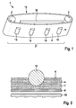
- the conveyor belt 10 comprises a support belt 6, on whose side directed to the outside, a flexible layer 7 is arranged with a magnetorheological fluid.
- a support belt 6 on whose side directed to the outside, a flexible layer 7 is arranged with a magnetorheological fluid.
- the article 14 is cylindrical, for example a cylindrical glass container for medicaments, which is pressed against the surface of the flexible layer 7, so that the flexible layer 7 partially encloses the cylindrical body of the article 14. Subsequently, the magnetic field device 30 is activated, so that the viscosity the magnetorheological fluid is changed, and the article 14 is held securely in the respective flexible layer 7.
- the magnetic field device 30 is disposed only on a portion of the conveyor belt 10, namely on the conveyor section 31 forming part region, which is used to convey the articles 14, so that not the entire conveyor belt 10 is stiffened by the magnetic field device 30 , As a result, problems on the pulleys 2, 3 can be avoided. As soon as the article passes outside the magnetic field generated by the magnetic field device 30, the stiffening (viscosity change) of the magnetorheological fluid is reversed and the article can be easily removed from the again very flexible layer 7 and fed, for example, a packaging machine or a filling device.
- articles 14 having a wide variety of geometric shapes can thus be transported easily with the same conveyor belt.
- a conversion or the like Is not necessary so that set-up times and downtime of machines do not apply.
- a fast format conversion to objects with other geometric formats can be made possible.
- FIGS. 3 to 7 show a second to sixth embodiment of the invention.
- the transporting device 1 further comprises a first and a second deflection roller 2, 3 and a tensioning roller 9.
- the circulating conveyor belt 10 has, on an outer-facing surface, a multiplicity of microstructures 5, which have a multiplicity of protruding areas in the micrometer range (between 1 and 1000 ⁇ m). Under the microstructures a layer with a magnetorheological fluid is arranged. Furthermore, a magnetic field device 30 is arranged along a conveying path 31.
- the reference numeral 8 denotes a Feed belt, with which products 14 are supplied to the transport device 1 according to the invention.
- a transfer of the product 14 from the conveyor belt 8 on the conveyor belt 10 takes place at a product transfer area 17 such that at the guide roller 81, a vertical distance A between the guide roller 81 and the first guide roller 2 is minimally smaller than a product height H, so that a Pressure force is generated during the passage of the product 14 between the two pulleys. As a result, the product 14 adheres particularly well to the conveyor belt 10.
- the transport device 1 according to the invention can be used for a wide variety of products 14, even if they have different sizes and / or different geometries. Furthermore, transfers of products 14 from the bottom to the top can be made possible in particular by means of the present invention. Furthermore, in particular the flexibility of positioning of the transport device according to the invention, in particular in connection with filling and / or packaging machines is significantly simplified.
- FIG. 4 shows a transport device 1 according to a third embodiment of the invention.
- the transport device 1 of the fourth exemplary embodiment comprises a conveyor belt 10 according to the invention and a transfer device 11.
- the transfer device 11 comprises in the third Embodiment, a second conveyor belt 12.
- the second conveyor belt 12 is disposed below the first conveyor belt 10 and further horizontally offset from the first conveyor belt 10. Thereby, an overlapping product transfer area 17 is obtained, on which the first conveyor belt 10 and the second conveyor belt 12 are arranged one above the other.
- a distance A between the first and second conveyor belt is smaller than a maximum product height H. This ensures that when the product 14 is conveyed into the product transfer area 17, a pressing force is exerted on the product 14 by the second transport device 20.
- the product 14 adheres better to the provided with microstructures 5 surface 4 of the first conveyor belt 10.
- a secure transfer of the product 14 from the upper run of the second conveyor belt 12 to the lower run of the first conveyor belt 10 is achieved by the transfer device 11.
- FIG. 5 shows a transport device 1 according to a fourth embodiment of the invention.
- the fourth embodiment also includes a transfer device 11 for transferring the products 14 to the first conveyor belt 10.
- the transfer device 11 comprises a second conveyor belt 12 and a third conveyor belt 13.
- the three conveyor belts 10, 12, 13 are arranged in the vertical direction, so that a side transfer is possible.
- the second conveyor belt 12 is arranged in series in front of the first conveyor belt 10.
- the third conveyor belt 13 is arranged parallel to the first and second conveyor belt.
- the third conveyor belt 13 covers at least partially both the first and the second conveyor belt.
- a lateral overlap region results both with the first conveyor belt 10 and the second conveyor belt 12.
- the products 14 are transported between the second conveyor belt 12 and the third conveyor belt 13 by pinching between the two conveyor belts in the direction of arrow B.
- a bridging element 18 is arranged, wherein the products 14 are pushed over the bridging element 18 by means of the third conveyor belt 13.
- a distance A between the third conveyor belt 13 and the first conveyor belt 10 is selected smaller than a height H of the products 14. In this way, a defined adhesion of the products 14 on the surface 4 by means of the microstructures 5 on the first conveyor belt 10 is achieved.
- the conveyor belts 10, 12, 13 of the fourth embodiment are aligned exactly in the vertical direction. It should be noted, however, that the conveyor belts can also be tilted, ie, can be arranged at any equal angle with respect to a horizontal plane.
- FIG. 6 shows a transport device 1 according to a fifth embodiment of the invention.
- This transport device 1 also includes a transfer device 11, which in the fifth embodiment, however, is an actuator 15 which actuates a pressure element 16.
- a transfer device 11 which in the fifth embodiment, however, is an actuator 15 which actuates a pressure element 16.
- the products 14 are pressed by means of the pressing member 16 against the vertically arranged conveyor belt 10 with a defined force.
- the products 14 in turn adhere very well to the surface of the conveyor belt 10 and it can be a simple lateral transfer realized.
- FIG. 7 shows a conveyor belt for a transport device according to a sixth embodiment of the invention.
- the flexible layer 7 is arranged between the outer layer with microstructures 5 and a strap 6.
- the conveyor belt 21 with high stability better adaptability to geometric shapes of the products 14, wherein, as in FIG. 7 shown, a partial enclosure of the product 14 is possible.
- the flexible layer can become viscous and the product 14 can be held securely.
- products with rounded or round outer surfaces, such as bottles can be better kept.
- FIGS. 8 and 9 show a transport device 1 according to a seventh embodiment of the invention.
- a gripper 40 having a first gripping arm 41 and a second gripping arm 42.
- first gripping arm 41, 42 At the end of each gripper arm 41, 42 each one covered by a membrane 44 flexible layer 43 is arranged.
- the first and second gripping arm 41, 42 are rotatable about an axis of rotation 45 against each other. This allows objects (not shown) between the two flexible layers 43 at the end of the gripping arms 41, 42 are gripped.
- the gripping arms 41, 42 are the same structure, wherein, as in FIG. 9 shown, the gripping arm 41 is applied to a housing 46 which holds the flexible layer 43.
- a magnetic field device 30 is arranged in the form of a coil. When the coil is energized, the flexible layer 43, which is filled with a magnetorheological fluid as in the previous embodiments, is stiffened, so that an object held between the gripping arms 41, 42 can be gripped securely by the gripping arms.
- the gripper 40 can perform various transport tasks for individual items. By the use of the flexible layers 43 at the end of the two gripper arms 41, 42, thus objects with a variety of geometric shapes can be safely gripped and released.
Landscapes
- Engineering & Computer Science (AREA)
- Mechanical Engineering (AREA)
- Structure Of Belt Conveyors (AREA)
- Belt Conveyors (AREA)
Description
Die vorliegende Erfindung betrifft eine Transportvorrichtung mit einer magnetorheologischen Flüssigkeit, welche verfestigbar ist, um zu transportierende Gegenstände zumindest teilweise zu umschließen und zu transportieren.The present invention relates to a transport device with a magnetorheological fluid which is solidifiable to at least partially enclose and transport objects to be transported.
Im Stand der Technik sind verschiedenste Transportaufgaben zu bewältigen. Ein Problemkreis bei der Handhabung von leicht zerbrechlichen Gütern ist beispielsweise die Handhabung derartiger Güter, ohne diese zu beschädigen. Beispielsweise in der Verpackungstechnik müssen Glasbehältnisse oder Vials, häufig gefüllt mit toxischen Stoffen oder gefährlichen Medikamenten, ohne Beschädigung gehandhabt werden. Dies wird bisher dadurch gelöst, dass jeweils speziell konstruierte Transportvorrichtungen vorgesehen werden, welche exakt auf die geometrischen Verhältnisse und Materialien der Behältnisse abgestimmt sind. Dies führt jedoch dazu, dass bei einem Wechsel eines Formats der Behältnisse auch die entsprechenden Transportvorrichtungen vorgehalten und gewechselt werden müssen, was zu Maschinenstillstandszeiten und erhöhten Anschaffungskosten führt.In the prior art, a variety of transport tasks are to be handled. One problem with handling easily breakable goods is, for example, the handling of such goods without damaging them. For example, in packaging technology, glass containers or vials, often filled with toxic substances or hazardous drugs, must be handled without damage. This has been solved by the fact that each specially designed transport devices are provided, which are tuned exactly to the geometric conditions and materials of the containers. However, this leads to the fact that when changing a format of the containers and the corresponding transport devices must be kept and changed, resulting in machine downtime and increased acquisition costs.
Aus dem Stand der Technik ist es weiterhin bekannt, magnetorheologische Flüssigkeiten, beispielsweise bei Stoßdämpfern von Fahrzeugen, zu verwenden. Diese magnetorheologischen Flüssigkeiten reagieren auf magnetische Felder und können dadurch versteift werden, so dass sich die Dämpfungseigenschaften des Stoßdämpfers ändern. Nach Entfernen des magnetischen Feldes nimmt die magnetorheologische Flüssigkeit wieder ihre Ausgangsform ein und weist wieder ausreichende Fließfähigkeiten auf.From the prior art, it is also known to use magnetorheological fluids, for example, in shock absorbers of vehicles. These magnetorheological fluids react to magnetic fields and can thereby be stiffened so that the damping characteristics of the shock absorber change. After removal of the magnetic field, the magnetorheological fluid returns to its initial shape and again has sufficient flowability.
Einschub für die Beschreibungseinleitung (anzufügen an Seite 1, Zeile 36 der ursprünglichen Beschreibung)Insert for introduction to the description (to be added to page 1, line 36 of the original description)
Aus der
Die erfindungsgemäße Transportvorrichtung mit den Merkmalen des Anspruchs 1 weist demgegenüber den Vorteil auf, dass mit der Transportvorrichtung problemlos Gegenstände mit verschiedensten geometrischen Formen und aus verschiedensten Materialien, insbesondere auch zerbrechlichen Materialien, wie Glas, transportiert werden können. Dabei ist die erfindungsgemäße Transportvorrichtung derart ausgebildet, dass sie zumindest teilweise die zu transportierenden Gegenstände umschließen kann. Dies wird erfindungsgemäß dadurch erreicht, dass die Transportvorrichtung eine Magnetfeldvorrichtung zur Erzeugung eines Magnetfelds und eine flexible Schicht mit einer magnetorheologischen Flüssigkeit aufweist. Die magnetorheologische Flüssigkeit ist mittels der Magnetfeldvorrichtung magnetisierbar, so dass die magnetische Flüssigkeit eine Viskositätsänderung derart erfährt, um zu transportierende Gegenstände zumindest teilweise zu umschließen und zu halten. Dadurch können die zu transportierenden Gegenstände unabhängig von ihrer geometrischen Form sicher und sanft transportiert werden, so dass auch zerbrechliche Gegenstände ohne Gefahr einer Beschädigung transportiert werden können. Es sei angemerkt, dass unter dem Begriff "Flüssigkeit" erfindungsgemäß sowohl tatsächliche Flüssigkeiten als auch ein Gel oder ein anderes zähflüssiges Fluid verstanden wird. Weiter ist die flexible Schicht mit der magnetorheologischen Flüssigkeit an einem Transportband angeordnet, wobei das Transportband vorzugsweise einen Tragriemen umfasst, an dessen Außenseite die flexible Schicht angeordnet ist. Hierdurch kann beispielsweise ein umlaufendes Transportband bereitgestellt werden, wobei beispielsweise auch ein seitlicher Transport oder ein Transport mit dem Untertrum des umlaufenden Transportbandes möglich ist. Ebenfalls ist auch ein vertikaler Transport der Gegenstände möglich.The transport device according to the invention with the features of claim 1 has the advantage that with the transport device easily objects with a variety of geometric shapes and materials, especially fragile materials such as glass, can be transported. In this case, the transport device according to the invention is designed such that it can at least partially enclose the objects to be transported. This is inventively achieved in that the transport device comprises a magnetic field device for generating a magnetic field and a flexible layer with a magnetorheological fluid. The magnetorheological fluid is magnetizable by means of the magnetic field device, so that the magnetic fluid undergoes a change in viscosity in such a way to at least partially enclose and hold objects to be transported. As a result, the objects to be transported can be transported safely and smoothly, regardless of their geometric shape, so that even fragile objects can be transported without risk of damage. It should be noted that the term "liquid" according to the invention is understood as meaning both actual liquids and a gel or other viscous fluid. Further, the flexible layer is arranged with the magnetorheological fluid on a conveyor belt, wherein the conveyor belt preferably comprises a support belt, on the outside of the flexible layer is arranged. In this way, for example, a circulating conveyor belt can be provided, wherein, for example, a lateral transport or transport with the lower run of the circulating conveyor belt is possible. Also, a vertical transport of the objects is possible.
Die Unteransprüche zeigen bevorzugte Weiterbildungen der Erfindung.The dependent claims show preferred developments of the invention.
Vorzugsweise ist die Magnetfeldvorrichtung derart angeordnet, dass nur Teilbereiche der magnetorheologischen Flüssigkeit magnetisierbar sind. Hierdurch können Transportaufgaben gelöst werden, bei denen beispielsweise bei einer Rückführung der Transportvorrichtung keine hohe Viskosität bzw. Versteifung der magnetorheologischen Flüssigkeit notwendig ist, z.B. bei umlaufenden Transportbändern.Preferably, the magnetic field device is arranged such that only partial regions of the magnetorheological fluid can be magnetized. As a result, transport tasks can be solved in which, for example, in a return of the transport device no high viscosity or stiffening of the magnetorheological fluid is necessary, for. with circulating conveyor belts.
Weiter bevorzugt weist die die magnetorheologischen Flüssigkeit umfassende flexible Schicht eine Oberfläche mit einer Vielzahl von Mikro-Strukturen mit vorstehenden Bereichen auf. Die vorstehenden Bereiche der Mikro-Strukturen kommen dabei bei einem Kontakt der Oberfläche mit dem zu transportierenden Gegenstand derart mit dem Gegenstand in Berührung, dass aufgrund der auftretenden Van-der-Waals-Kräfte der Gegenstand an der Oberfläche anhaftet. Hierdurch wird zusätzlich noch eine Sicherheit durch die zusätzliche äußere Schicht von Mikro-Strukturen für ein Halten der Gegenstände während des Transports bereitgestellt.More preferably, the flexible layer comprising the magnetorheological fluid has a surface having a plurality of microstructures with protruding portions. The protruding areas of the microstructures come into contact with the object during contact of the surface with the object to be transported in such a way that due to the van der Waals forces that occur, the object adheres to the surface. This additionally provides security through the additional outer layer of microstructures for holding the articles during transport.
Gemäß einer bevorzugten Ausgestaltung ist die Magnetfeldvorrichtung ein Permanentmagnet, welcher ortsfest oder bewegbar sein kann. Alternativ oder zusätzlich umfasst die Magnetfeldvorrichtung ferner einen elektrische Spule. Der Permanentmagnet kann beispielsweise beweglich angeordnet sein und für eine Versteifung der magnetorheologischen Flüssigkeit in die Nähe der magnetorheologischen Flüssigkeit bewegt werden. Sobald die Transportaufgabe beendet ist, wird der Permanentmagnet wieder von der magnetorheologischen Flüssigkeit wegbewegt, so dass die Versteifung wieder aufgehoben wird. Alternativ kann der Permanentmagnet auch ortsfest angeordnet sein und zusätzlich ein elektrischer Leiter in der Nähe des Permanentmagneten angeordnet sein, so dass bei Anlegen einer Spannung an den elektrischen Leiter das magnetische Feld des Permanentmagneten aufgehoben wird oder abgeschwächt wird und so die Eigenschaften der magnetorheologischen Flüssigkeit geändert werden.According to a preferred embodiment, the magnetic field device is a permanent magnet, which may be stationary or movable. Alternatively or additionally, the magnetic field device further comprises an electrical coil. The permanent magnet may, for example, be movably arranged and moved in the vicinity of the magnetorheological fluid for stiffening the magnetorheological fluid. Once the transport task is completed, the permanent magnet is again moved away from the magnetorheological fluid, so that the stiffening is canceled. Alternatively, the permanent magnet can also be arranged stationary and additionally an electrical conductor can be arranged in the vicinity of the permanent magnet, so that when a voltage is applied to the electrical conductor, the magnetic field of the permanent magnet is canceled or weakened and so the properties of the magnetorheological fluid are changed ,
Besonders bevorzugt ist die Magnetfeldvorrichtung parallel zu einer Förderstrecke des Transportbandes, z.B. einem Untertrum, angeordnet.Particularly preferably, the magnetic field device is parallel to a conveying path of the conveyor belt, e.g. a lower strand, arranged.
Gemäß einer alternativen Ausführung nicht Teil der Erfindung, ist die flexible Schicht an einem Greifer angeordnet, welcher die zu transportierenden Gegenstände greift. Hierbei sind insbesondere die Greiferbacken des Greifers mit der magnetorheologischen Flüssigkeit ausgestattet, um ein sicheres Greifen des Gegenstandes zu ermöglichen. Besonders bevorzugt umfasst der Greifer dabei zwei einander gegenüberliegende Arme, welche jeweils mit der flexiblen Schicht ausgestattet sind.According to an alternative embodiment not part of the invention, the flexible layer is arranged on a gripper which grips the objects to be transported. In this case, in particular the gripper jaws of the gripper are equipped with the magnetorheological fluid to secure gripping the To enable object. Particularly preferably, the gripper comprises two opposing arms, which are each equipped with the flexible layer.
Gemäß einer weiteren Ausgestaltung der Erfindung wird eine Transportanordnung vorgeschlagen, welche eine erfindungsgemäße Transportvorrichtung aufweist sowie eine Übergabevorrichtung. Die Übergabevorrichtung ist eingerichtet, ein Produkt auf das erste Transportband derart zu übergeben, dass das Produkt mit einer definierten Kraft auf die Oberfläche des Transportbandes andrückbar ist. Hierdurch wird sichergestellt, dass das Produkt mit einer ausreichenden Kraft übergeben wird und sicher am Transportband anhaftet und die Vielzahl von Mikrostrukturen die jeweiligen notwendigen Van-der-Waals-Kräfte bereitstellen können.According to a further embodiment of the invention, a transport arrangement is proposed, which has a transport device according to the invention and a transfer device. The transfer device is set up to transfer a product to the first conveyor belt in such a way that the product can be pressed onto the surface of the conveyor belt with a defined force. This ensures that the product is transferred with a sufficient force and securely adheres to the conveyor belt and the plurality of microstructures can provide the respective necessary Van der Waals forces.
Vorzugsweise umfasst die Transportanordnung als Übergabevorrichtung ein zweites Transportband, welches unterhalb des ersten Transportbandes und vertikal und horizontal versetzt zum ersten Transportband angeordnet ist. Hierdurch ergibt sich ein sich überschneidender Produktübergabebereich, wobei ein Vertikalabstand zwischen dem ersten und zweiten Transportband derart gewählt ist, dass ein Produkt mit einer definierten Kraft vom zweiten Transportband auf das erste Transportband übergebbar ist. Somit kann eine einfach aufgebaute und kostengünstige Übergabevorrichtung bereitgestellt werden. Weiterhin kann die Übergabekraft einfach eingestellt werden, indem beispielsweise das erste und/oder zweite Transportband mit einer anderen Spannung versehen wird.Preferably, the transport arrangement comprises as a transfer device, a second conveyor belt, which is arranged below the first conveyor belt and vertically and horizontally offset from the first conveyor belt. This results in an overlapping product transfer area, wherein a vertical distance between the first and second conveyor belt is selected such that a product with a defined force from the second conveyor belt can be transferred to the first conveyor belt. Thus, a simple and inexpensive transfer device can be provided. Furthermore, the transfer force can be easily adjusted, for example, by providing the first and / or second conveyor belt with a different voltage.
Gemäß einer bevorzugten Alternative umfasst die Übergabevorrichtung für die Transportbandanordnung ein zweites und ein drittes Transportband. Dabei ist das zweite Transportband in Reihe zum ersten Transportband angeordnet, d.h., das zweite Transportband ist dem ersten Transportband in Reihe vorgeschaltet, und das dritte Transportband ist parallel zum ersten und zweiten Transportband angeordnet. Dabei überdeckt das dritte Transportband sowohl das erste als auch das zweite Transportband zumindest teilweise. Somit wird eine Übergabe eines Produkts derart realisiert, dass das Produkt zuerst zwischen dem zweiten und dritten Transportband eingeklemmt ist und in Transportrichtung gefördert wird und dann vom zweiten Transportband auf das erste Transportband übergeben wird, wobei das Produkt zuerst noch zwischen dem zweiten und dritten Transportband und dann dem dritten und ersten Transportband geklemmt ist. Durch das Klemmen wird eine Andrückkraft vom dritten Transportband auf das Produkt und an das erste Transportband ausgeübt und somit die Aktivierung des Adhäsionsprinzips zwischen dem Produkt und dem ersten Transportband erreicht. Besonders bevorzugt sind dabei das erste, zweite und dritte Transportband derart angeordnet, dass eine seitliche Produktübergabe erfolgt. Insbesondere sind die drei Transportbänder dabei im Wesentlichen vertikal, besonders bevorzugt exakt vertikal, angeordnet.
Ferner betrifft die vorliegende Erfindung eine Verwendung einer magnetorheologischen Flüssigkeit in einer Transportvorrichtung nach Anspruch 1. Hierdurch können auf überraschend einfache Weise vielfältige Transportaufgaben gelöst werden und insbesondere eine erhöhte Flexibilität der Transportanordnung erreicht werden, ohne dass eine Formatumstellung zum Transport von Gegenständen mit unterschiedlichen geometrischen Formaten notwendig ist. Ferner betrifft die vorliegende Erfindung vorzugsweise die Verwendung einer mikrostrukturierten Oberfläche mit einer Vielzahl von vorstehenden Bereichen, die in einem Bereich von 1 bis 1000 µm vorstehen, an einem Transportband einer Transportvorrichtung in Verbindung mit einer magnetorheologischen Schicht.
Somit wird erfindungsgemäß zum ersten Mal vorgeschlagen, derartige Mikrostrukturen an einem Transportband zu verwenden, wodurch sich viele überraschende Vorteile bei der Lösung von Transportaufgaben mit Transportbändern ergeben.According to a preferred alternative, the transfer device for the conveyor belt arrangement comprises a second and a third conveyor belt. In this case, the second conveyor belt is arranged in series with the first conveyor belt, ie, the second conveyor belt is connected upstream of the first conveyor belt in series, and the third conveyor belt is arranged parallel to the first and second conveyor belt. In this case, the third conveyor belt covers at least partially both the first and the second conveyor belt. Thus, a transfer of a product is realized such that the product is first clamped between the second and third conveyor belt and conveyed in the transport direction and then transferred from the second conveyor belt on the first conveyor belt is, wherein the product is first clamped between the second and third conveyor belt and then the third and first conveyor belt. By clamping a pressing force is exerted by the third conveyor belt on the product and on the first conveyor belt, thus achieving the activation of the adhesion principle between the product and the first conveyor belt. Particularly preferably, the first, second and third conveyor belts are arranged in such a way that a lateral product transfer takes place. In particular, the three conveyor belts are arranged substantially vertically, particularly preferably exactly vertically.
Furthermore, the present invention relates to a use of a magnetorheological fluid in a transport device according to claim 1. This can be solved in a surprisingly simple way diverse transport tasks and in particular increased flexibility of the transport arrangement can be achieved without a format change necessary for the transport of objects with different geometric formats is. Further, the present invention preferably relates to the use of a microstructured surface having a plurality of protruding portions protruding in a range of 1 to 1000 μm on a transporting belt of a transporting device in conjunction with a magnetorheological layer.
Thus, according to the invention it is proposed for the first time to use such microstructures on a conveyor belt, which results in many surprising advantages in the solution of transport tasks with conveyor belts.
Nachfolgend werden bevorzugte Ausführungsbeispiele der Erfindung unter Bezugnahme auf die begleitende Zeichnung im Detail beschrieben, wobei gleiche bzw. funktional gleiche Teile mit den gleichen Bezugszeichen bezeichnet sind. In der Zeichnung ist:
- Figur 1
- eine schematische, perspektivische Ansicht einer Transportvorrichtung gemäß einem ersten Ausführungsbeispiel der Erfindung,
Figur 2- eine schematische, geschnittene Ansicht der Transportvorrichtung von
Figur 1 , Figuren 3 bis 6- Transportvorrichtungen gemäß einem zweiten, dritten, vierten und fünften Ausführungsbeispiel,
- Figur 7
- eine schematische Schnittansicht einer Transportvorrichtung gemäß einem sechsten Ausführungsbeispiel der Erfindung, und
Figuren 8 und 9- Ansichten einer Transportvorrichtung gemäß einem siebten Ausführungsbeispiel der Erfindung.
- FIG. 1
- a schematic, perspective view of a transport device according to a first embodiment of the invention,
- FIG. 2
- a schematic, sectional view of the transport device of
FIG. 1 . - FIGS. 3 to 6
- Transport devices according to a second, third, fourth and fifth embodiment,
- FIG. 7
- a schematic sectional view of a transport device according to a sixth embodiment of the invention, and
- FIGS. 8 and 9
- Views of a transport device according to a seventh embodiment of the invention.
Bevorzugte Ausführungsformen der ErfindungPreferred embodiments of the invention
Nachfolgend wird unter Bezugnahme auf die
Wie aus
Wie insbesondere aus
In diesem Ausführungsbeispiel ist der Gegenstand 14 zylinderförmig, beispielsweise ein zylinderförmiger Glasbehälter für Medikamente, welcher gegen die Oberfläche der flexiblen Schicht 7 gedrückt wird, so dass die flexible Schicht 7 den Zylinderkörper des Gegenstands 14 teilweise umschließt. Anschließend wird die Magnetfeldvorrichtung 30 aktiviert, so dass die Viskosität der magnetorheologischen Flüssigkeit geändert wird, und der Gegenstand 14 sicher in der jeweils flexiblen Schicht 7 gehalten wird.In this embodiment, the
Wie aus
Durch die erfindungsgemäße Idee können somit Gegenstände 14 mit verschiedensten geometrischen Formen problemlos mit dem gleichen Transportband transportiert werden. Eine Umrüstung oder dgl. ist nicht notwendig, so dass Rüstzeiten und Stillstandszeiten von Maschinen nicht anfallen. Somit kann eine schnelle Formatumstellung auf Gegenstände mit anderen geometrischen Formaten ermöglicht werden.By virtue of the idea according to the invention,
Die
Nachfolgend wird unter Bezugnahme auf
Durch die Mikrostrukturen 5 auf der Oberfläche 4 des Transportbandes 10 können Gegenstände aufgrund der zwischen dem Gegenstand und den Mikrostrukturen auftretenden Van-der-Waals-Kräfte an der Oberfläche des Transportbandes 10 anhaften. Hierbei ergeben sich durch die Vielzahl von vorstehenden Bereichen (mehrere Millionen) eine ausreichende Haltekraft, obwohl jeder vorstehende Bereich nur eine winzige Haltekraft bereitstellt, aber die Summe aller winzigen Haltekräfte es ermöglicht, ein Produkt, wie in
Eine Übergabe des Produkts 14 von dem Zuführband 8 auf das Transportband 10 erfolgt dabei an einem Produktübergabebereich 17 derart, dass an der Umlenkrolle 81 ein senkrechter Abstand A zwischen der Umlenkrolle 81 und der ersten Umlenkrolle 2 minimal kleiner ist als eine Produkthöhe H, so dass eine Andrückkraft während des Durchlaufens des Produkts 14 zwischen den beiden Umlenkrollen erzeugt wird. Hierdurch haftet das Produkt 14 besonders gut an dem Transportband 10.A transfer of the
Somit kann erfindungsgemäß eine Förderung von Produkten 14 an einem Untertrum des Transportbandes 10 ermöglicht werden, wodurch insbesondere bei Formatumstellungen kein Wechsel des Transportbandes notwendig ist. Somit kann die erfindungsgemäße Transportvorrichtung 1 für verschiedenste Produkte 14 verwendet werden, auch wenn diese unterschiedliche Größen und/oder unterschiedliche Geometrien aufweisen. Ferner können mittels der vorliegenden Erfindung insbesondere auch Übergaben von Produkten 14 von unten nach oben ermöglicht werden. Weiterhin wird insbesondere auch die Flexibilität der Positionierung der erfindungsgemäßen Transportvorrichtung, insbesondere in Verbindung mit Abfüll- und/oder Verpackungsmaschinen deutlich vereinfacht.Thus, according to the invention, a promotion of
Die
Die Greifarme 41, 42 sind gleich aufgebaut, wobei, wie in
Nach Beendigung der Transportaufgabe wird die Bestromung der Spulen an den beiden Greifarmen 41, 42 beendet, so dass die magnetorheologische Flüssigkeit wieder in ihren flüssigen Ausgangszustand zurückkehrt, so dass die Greifarme 41, 42 geöffnet werden können und der dazwischen gegriffene Gegenstand freigegeben wird. Es sei angemerkt, dass der Greifer 40 verschiedene Transportaufgaben für einzelne Gegenstände durchführen kann. Durch die Verwendung der flexiblen Schichten 43 am Ende der beiden Greifarme 41, 42, können somit Gegenstände mit verschiedensten geometrischen Formen sicher gegriffen und freigegeben werden.After completion of the transport task, the energization of the coils on the two gripping
Claims (11)
- Transport device, comprising:- a magnetic field device (30) for generating a magnetic field, and- a flexible layer (7; 43) for transporting objects (14),- wherein the flexible layer comprises a magnetorheological fluid, and- wherein the magnetorheological fluid can be magnetized by means of the magnetic field device (30) such that a viscosity of the magnetorheological fluid is altered in order to enclose at least partially objects (14) that are to be transported,characterized in that the flexible layer (7) is arranged on a transport belt (10).
- Transport device according to Claim 1, characterized in that the magnetic field device (30) is arranged in such a way that only subregions of the magnetorheological fluid are magnetizable.
- Transport device according to one of the preceding claims, characterized in that the flexible layer (7; 43) has a surface (4) with a multiplicity of microstructures (5) with protruding regions such that, when the surface (4) is in contact with an object (14), the object adheres to the surface (4) as a result of the van der Waals forces occurring.
- Transport device according to one of the preceding claims, characterized in that the magnetic field device (30) comprises a permanent magnet and/or in that the magnetic field device (30) comprises an electrical coil.
- Transport device according to one of the preceding claims, characterized in that the transport belt (10) comprises a carrying belt (6).
- Transport device according to Claim 5, characterized in that the magnetic field device (30) is arranged parallel to a conveying section (31) of the transport belt (10).
- Transport arrangement, comprising:- a transport device according to one of the preceding claims, and- a transfer device (11), which is designed to transfer an object (14) to the first transport belt (10) such that the object (14) can be pressed with a defined force onto the surface (4) of the first transport belt (10).
- Transport arrangement according to Claim 7, characterized in that the transfer device comprises a second transport belt (12), which is arranged underneath the first transport belt (10) such that there is an overlapping product transfer region (17) between the first and second transport belts, wherein the vertical distance (A) between the first transport belt (10) and the second transport belt (12) is chosen such that an object can be transferred with a defined force from the second transport belt (12) onto the first transport belt (10).
- Transport arrangement according to Claim 7, characterized in that the transfer device (11) comprises a second transport belt (12) and a third transport belt (13), wherein the second transport belt (12) is arranged ahead of the first transport belt (10) in series with the first transport belt and the third transport belt (13) is arranged parallel to the first and second transport belts (10, 12), wherein the third transport belt (13) at least partially overlaps both the first transport belt (10) and the second transport belt (12) and the first, second and third transport belts (10, 12, 13) are arranged substantially in the vertical direction in order to make a lateral transfer of the object (14) possible.
- Transport arrangement according to Claim 7, characterized in that the transfer device (11) comprises an actuator (15) and a pressure-applying element (16), which can be actuated by the actuator (15) in order to press an object against the first transport belt (10).
- Use of a magnetorheological fluid in a transport device (1) according to Claim 1.
Applications Claiming Priority (2)
| Application Number | Priority Date | Filing Date | Title |
|---|---|---|---|
| DE201210207326 DE102012207326A1 (en) | 2012-05-03 | 2012-05-03 | Transport device with magnetorheological fluid |
| PCT/EP2013/055760 WO2013164126A1 (en) | 2012-05-03 | 2013-03-20 | Conveyor device comprising magnetorheological fluid |
Publications (2)
| Publication Number | Publication Date |
|---|---|
| EP2844591A1 EP2844591A1 (en) | 2015-03-11 |
| EP2844591B1 true EP2844591B1 (en) | 2016-09-07 |
Family
ID=48044749
Family Applications (1)
| Application Number | Title | Priority Date | Filing Date |
|---|---|---|---|
| EP13713388.0A Active EP2844591B1 (en) | 2012-05-03 | 2013-03-20 | Transport device with magnetorheological fluid |
Country Status (3)
| Country | Link |
|---|---|
| EP (1) | EP2844591B1 (en) |
| DE (1) | DE102012207326A1 (en) |
| WO (1) | WO2013164126A1 (en) |
Cited By (1)
| Publication number | Priority date | Publication date | Assignee | Title |
|---|---|---|---|---|
| CN119911557A (en) * | 2025-04-02 | 2025-05-02 | 联钢精密科技(中国)有限公司 | A storage silo with automatic loading function |
Families Citing this family (4)
| Publication number | Priority date | Publication date | Assignee | Title |
|---|---|---|---|---|
| CN106241703B (en) * | 2016-09-29 | 2018-07-27 | 台州市智诚工业设计有限公司 | A kind of pail pack conveying mechanism with buffer gear |
| DE102020103358A1 (en) | 2020-02-11 | 2021-08-12 | Voith Patent Gmbh | Covering with activatable adhesive effect |
| CN115196251B (en) * | 2022-06-30 | 2023-07-25 | 北京城建集团有限责任公司 | Medical case commodity circulation conveying equipment |
| CN120890908A (en) * | 2025-09-28 | 2025-11-04 | 南通亚泰蜡业工艺品有限公司 | A detection device for electronic candle casings based on novel environmentally friendly and recyclable materials |
Family Cites Families (11)
| Publication number | Priority date | Publication date | Assignee | Title |
|---|---|---|---|---|
| DE7200003U (en) * | 1974-08-29 | Institut Foerster F Pruefgeraetebau | ||
| GB9619066D0 (en) * | 1996-09-12 | 1996-10-23 | Univ Brunel | Gripper mechanism |
| DE10145931B4 (en) * | 2001-09-18 | 2006-01-05 | Rag Aktiengesellschaft | Conveyor belt for bulk material |
| US6827822B2 (en) * | 2001-11-09 | 2004-12-07 | Temple University Of The Commonwealth System Of Higher Education | Method and apparatus for increasing and modulating the yield shear stress of electrorheological fluids |
| EP1367027A3 (en) * | 2002-10-03 | 2004-10-27 | Bystronic Maschinen AG | Apparatus and method for breaking open scored glass sheets |
| DE112005001458T5 (en) * | 2004-06-16 | 2007-05-03 | Ricardo Uk Ltd., Shoreham-By-Sea | Rotary fluid coupling |
| DE102008020628A1 (en) * | 2007-04-25 | 2008-10-30 | Thyssenkrupp Krause Gmbh | Method e.g. for braking work piece carrier, involves stopping manufacturing or assembly line moving workpiece carrier at nominal position |
| DE202008004820U1 (en) * | 2008-04-07 | 2008-08-21 | Eble, Markus | Transport device for guiding and depositing panels |
| US9102030B2 (en) * | 2010-07-09 | 2015-08-11 | Corning Incorporated | Edge finishing apparatus |
| DE102010051872B4 (en) * | 2010-11-22 | 2021-10-28 | Hitachi Astemo, Ltd. | Vibration damper assembly |
| DE102010056036A1 (en) * | 2010-12-15 | 2012-06-21 | Wörner Automatisierungstechnik GmbH | Stop module for position-accurate holding of workpiece in clean room in field of e.g. food industry, has cylinder filled with fluid whose viscosity is variably adjustable, and brake element including actuator to change viscosity of fluid |
-
2012
- 2012-05-03 DE DE201210207326 patent/DE102012207326A1/en not_active Withdrawn
-
2013
- 2013-03-20 WO PCT/EP2013/055760 patent/WO2013164126A1/en not_active Ceased
- 2013-03-20 EP EP13713388.0A patent/EP2844591B1/en active Active
Cited By (2)
| Publication number | Priority date | Publication date | Assignee | Title |
|---|---|---|---|---|
| CN119911557A (en) * | 2025-04-02 | 2025-05-02 | 联钢精密科技(中国)有限公司 | A storage silo with automatic loading function |
| CN119911557B (en) * | 2025-04-02 | 2025-06-27 | 联钢精密科技(中国)有限公司 | A storage silo with automatic loading function |
Also Published As
| Publication number | Publication date |
|---|---|
| WO2013164126A1 (en) | 2013-11-07 |
| DE102012207326A1 (en) | 2013-11-07 |
| EP2844591A1 (en) | 2015-03-11 |
Similar Documents
| Publication | Publication Date | Title |
|---|---|---|
| EP2844590B1 (en) | Transport device with improved adhesion characteristics | |
| EP2844591B1 (en) | Transport device with magnetorheological fluid | |
| DE102012009649A1 (en) | Gripping device e.g. vacuum gripper, for attaching at robot for e.g. picking cardboard box with yoghurt cups from container, has rolling-on modules rotatable around axis parallel to transport directions of modules | |
| EP2024237A1 (en) | Device and method for reinforcing a blister | |
| EP2729377A1 (en) | Pack and method for producing such a pack | |
| WO2013143772A1 (en) | Pushing device, transport arrangement and packaging arrangement | |
| DE102011054994A1 (en) | Container with carrying handle, method and apparatus for producing such containers | |
| DE102010032164B4 (en) | Method of packaging objects of different sizes | |
| WO2019129394A1 (en) | Packaging device and method for operating a packaging device | |
| DE102012016698A1 (en) | Device for packaging objects | |
| EP3732108B1 (en) | Packaging device and method for operating the packaging device | |
| EP4007722B1 (en) | Device and method for forming bundles of individual packages | |
| EP3743338B1 (en) | Device and method for applying a protective element to a packaging | |
| EP3732109B1 (en) | Packaging device and method for operating a packaging device | |
| DE19842362C2 (en) | Method and device for opening prefabricated bag packages | |
| DE102011087052A1 (en) | Device and method for handling containers | |
| DE102016206652A1 (en) | Device and method for handling in at least one row successively moving piece goods | |
| DE102013113321A1 (en) | Method and device for testing adhesions between articles of a container | |
| EP3564136A1 (en) | Packaging machine with conveyor device | |
| EP3710360B1 (en) | BAG FILLING DEVICE AND METHOD FOR PROCESSING AND FILLING BAGS | |
| EP2206652B1 (en) | Device and method for handling two superimposed films and bag produced according to said method | |
| DE102021211425A1 (en) | Equipment for handling objects | |
| EP2878941B1 (en) | Method and device for testing adhesive joints between articles of a container | |
| DE102022132191A1 (en) | Gripper head and method for gripping and manipulating piece goods | |
| EP2383188A1 (en) | Method and device for filling and sealing folding boxes |
Legal Events
| Date | Code | Title | Description |
|---|---|---|---|
| PUAI | Public reference made under article 153(3) epc to a published international application that has entered the european phase |
Free format text: ORIGINAL CODE: 0009012 |
|
| 17P | Request for examination filed |
Effective date: 20141203 |
|
| AK | Designated contracting states |
Kind code of ref document: A1 Designated state(s): AL AT BE BG CH CY CZ DE DK EE ES FI FR GB GR HR HU IE IS IT LI LT LU LV MC MK MT NL NO PL PT RO RS SE SI SK SM TR |
|
| AX | Request for extension of the european patent |
Extension state: BA ME |
|
| DAX | Request for extension of the european patent (deleted) | ||
| 17Q | First examination report despatched |
Effective date: 20160201 |
|
| GRAP | Despatch of communication of intention to grant a patent |
Free format text: ORIGINAL CODE: EPIDOSNIGR1 |
|
| INTG | Intention to grant announced |
Effective date: 20160603 |
|
| GRAS | Grant fee paid |
Free format text: ORIGINAL CODE: EPIDOSNIGR3 |
|
| GRAA | (expected) grant |
Free format text: ORIGINAL CODE: 0009210 |
|
| AK | Designated contracting states |
Kind code of ref document: B1 Designated state(s): AL AT BE BG CH CY CZ DE DK EE ES FI FR GB GR HR HU IE IS IT LI LT LU LV MC MK MT NL NO PL PT RO RS SE SI SK SM TR |
|
| REG | Reference to a national code |
Ref country code: GB Ref legal event code: FG4D Free format text: NOT ENGLISH |
|
| REG | Reference to a national code |
Ref country code: CH Ref legal event code: EP |
|
| REG | Reference to a national code |
Ref country code: IE Ref legal event code: FG4D Free format text: LANGUAGE OF EP DOCUMENT: GERMAN |
|
| REG | Reference to a national code |
Ref country code: AT Ref legal event code: REF Ref document number: 826635 Country of ref document: AT Kind code of ref document: T Effective date: 20161015 |
|
| REG | Reference to a national code |
Ref country code: DE Ref legal event code: R096 Ref document number: 502013004358 Country of ref document: DE |
|
| REG | Reference to a national code |
Ref country code: NL Ref legal event code: FP |
|
| REG | Reference to a national code |
Ref country code: LT Ref legal event code: MG4D |
|
| PG25 | Lapsed in a contracting state [announced via postgrant information from national office to epo] |
Ref country code: FI Free format text: LAPSE BECAUSE OF FAILURE TO SUBMIT A TRANSLATION OF THE DESCRIPTION OR TO PAY THE FEE WITHIN THE PRESCRIBED TIME-LIMIT Effective date: 20160907 Ref country code: NO Free format text: LAPSE BECAUSE OF FAILURE TO SUBMIT A TRANSLATION OF THE DESCRIPTION OR TO PAY THE FEE WITHIN THE PRESCRIBED TIME-LIMIT Effective date: 20161207 Ref country code: HR Free format text: LAPSE BECAUSE OF FAILURE TO SUBMIT A TRANSLATION OF THE DESCRIPTION OR TO PAY THE FEE WITHIN THE PRESCRIBED TIME-LIMIT Effective date: 20160907 Ref country code: LT Free format text: LAPSE BECAUSE OF FAILURE TO SUBMIT A TRANSLATION OF THE DESCRIPTION OR TO PAY THE FEE WITHIN THE PRESCRIBED TIME-LIMIT Effective date: 20160907 Ref country code: RS Free format text: LAPSE BECAUSE OF FAILURE TO SUBMIT A TRANSLATION OF THE DESCRIPTION OR TO PAY THE FEE WITHIN THE PRESCRIBED TIME-LIMIT Effective date: 20160907 |
|
| PG25 | Lapsed in a contracting state [announced via postgrant information from national office to epo] |
Ref country code: SE Free format text: LAPSE BECAUSE OF FAILURE TO SUBMIT A TRANSLATION OF THE DESCRIPTION OR TO PAY THE FEE WITHIN THE PRESCRIBED TIME-LIMIT Effective date: 20160907 Ref country code: GR Free format text: LAPSE BECAUSE OF FAILURE TO SUBMIT A TRANSLATION OF THE DESCRIPTION OR TO PAY THE FEE WITHIN THE PRESCRIBED TIME-LIMIT Effective date: 20161208 Ref country code: LV Free format text: LAPSE BECAUSE OF FAILURE TO SUBMIT A TRANSLATION OF THE DESCRIPTION OR TO PAY THE FEE WITHIN THE PRESCRIBED TIME-LIMIT Effective date: 20160907 Ref country code: ES Free format text: LAPSE BECAUSE OF FAILURE TO SUBMIT A TRANSLATION OF THE DESCRIPTION OR TO PAY THE FEE WITHIN THE PRESCRIBED TIME-LIMIT Effective date: 20160907 |
|
| REG | Reference to a national code |
Ref country code: FR Ref legal event code: PLFP Year of fee payment: 5 |
|
| PG25 | Lapsed in a contracting state [announced via postgrant information from national office to epo] |
Ref country code: EE Free format text: LAPSE BECAUSE OF FAILURE TO SUBMIT A TRANSLATION OF THE DESCRIPTION OR TO PAY THE FEE WITHIN THE PRESCRIBED TIME-LIMIT Effective date: 20160907 Ref country code: RO Free format text: LAPSE BECAUSE OF FAILURE TO SUBMIT A TRANSLATION OF THE DESCRIPTION OR TO PAY THE FEE WITHIN THE PRESCRIBED TIME-LIMIT Effective date: 20160907 |
|
| PG25 | Lapsed in a contracting state [announced via postgrant information from national office to epo] |
Ref country code: IS Free format text: LAPSE BECAUSE OF FAILURE TO SUBMIT A TRANSLATION OF THE DESCRIPTION OR TO PAY THE FEE WITHIN THE PRESCRIBED TIME-LIMIT Effective date: 20170107 Ref country code: SM Free format text: LAPSE BECAUSE OF FAILURE TO SUBMIT A TRANSLATION OF THE DESCRIPTION OR TO PAY THE FEE WITHIN THE PRESCRIBED TIME-LIMIT Effective date: 20160907 Ref country code: CZ Free format text: LAPSE BECAUSE OF FAILURE TO SUBMIT A TRANSLATION OF THE DESCRIPTION OR TO PAY THE FEE WITHIN THE PRESCRIBED TIME-LIMIT Effective date: 20160907 Ref country code: PL Free format text: LAPSE BECAUSE OF FAILURE TO SUBMIT A TRANSLATION OF THE DESCRIPTION OR TO PAY THE FEE WITHIN THE PRESCRIBED TIME-LIMIT Effective date: 20160907 Ref country code: SK Free format text: LAPSE BECAUSE OF FAILURE TO SUBMIT A TRANSLATION OF THE DESCRIPTION OR TO PAY THE FEE WITHIN THE PRESCRIBED TIME-LIMIT Effective date: 20160907 Ref country code: PT Free format text: LAPSE BECAUSE OF FAILURE TO SUBMIT A TRANSLATION OF THE DESCRIPTION OR TO PAY THE FEE WITHIN THE PRESCRIBED TIME-LIMIT Effective date: 20170109 Ref country code: BG Free format text: LAPSE BECAUSE OF FAILURE TO SUBMIT A TRANSLATION OF THE DESCRIPTION OR TO PAY THE FEE WITHIN THE PRESCRIBED TIME-LIMIT Effective date: 20161207 |
|
| REG | Reference to a national code |
Ref country code: DE Ref legal event code: R097 Ref document number: 502013004358 Country of ref document: DE |
|
| PLBE | No opposition filed within time limit |
Free format text: ORIGINAL CODE: 0009261 |
|
| STAA | Information on the status of an ep patent application or granted ep patent |
Free format text: STATUS: NO OPPOSITION FILED WITHIN TIME LIMIT |
|
| PG25 | Lapsed in a contracting state [announced via postgrant information from national office to epo] |
Ref country code: DK Free format text: LAPSE BECAUSE OF FAILURE TO SUBMIT A TRANSLATION OF THE DESCRIPTION OR TO PAY THE FEE WITHIN THE PRESCRIBED TIME-LIMIT Effective date: 20160907 |
|
| 26N | No opposition filed |
Effective date: 20170608 |
|
| PG25 | Lapsed in a contracting state [announced via postgrant information from national office to epo] |
Ref country code: SI Free format text: LAPSE BECAUSE OF FAILURE TO SUBMIT A TRANSLATION OF THE DESCRIPTION OR TO PAY THE FEE WITHIN THE PRESCRIBED TIME-LIMIT Effective date: 20160907 |
|
| GBPC | Gb: european patent ceased through non-payment of renewal fee |
Effective date: 20170320 |
|
| PG25 | Lapsed in a contracting state [announced via postgrant information from national office to epo] |
Ref country code: MC Free format text: LAPSE BECAUSE OF FAILURE TO SUBMIT A TRANSLATION OF THE DESCRIPTION OR TO PAY THE FEE WITHIN THE PRESCRIBED TIME-LIMIT Effective date: 20160907 |
|
| REG | Reference to a national code |
Ref country code: IE Ref legal event code: MM4A |
|
| PG25 | Lapsed in a contracting state [announced via postgrant information from national office to epo] |
Ref country code: LU Free format text: LAPSE BECAUSE OF NON-PAYMENT OF DUE FEES Effective date: 20170320 |
|
| PG25 | Lapsed in a contracting state [announced via postgrant information from national office to epo] |
Ref country code: GB Free format text: LAPSE BECAUSE OF NON-PAYMENT OF DUE FEES Effective date: 20170320 Ref country code: IE Free format text: LAPSE BECAUSE OF NON-PAYMENT OF DUE FEES Effective date: 20170320 |
|
| REG | Reference to a national code |
Ref country code: BE Ref legal event code: MM Effective date: 20170331 |
|
| REG | Reference to a national code |
Ref country code: FR Ref legal event code: PLFP Year of fee payment: 6 |
|
| PG25 | Lapsed in a contracting state [announced via postgrant information from national office to epo] |
Ref country code: BE Free format text: LAPSE BECAUSE OF NON-PAYMENT OF DUE FEES Effective date: 20170331 |
|
| PG25 | Lapsed in a contracting state [announced via postgrant information from national office to epo] |
Ref country code: MT Free format text: LAPSE BECAUSE OF FAILURE TO SUBMIT A TRANSLATION OF THE DESCRIPTION OR TO PAY THE FEE WITHIN THE PRESCRIBED TIME-LIMIT Effective date: 20160907 |
|
| PG25 | Lapsed in a contracting state [announced via postgrant information from national office to epo] |
Ref country code: AL Free format text: LAPSE BECAUSE OF FAILURE TO SUBMIT A TRANSLATION OF THE DESCRIPTION OR TO PAY THE FEE WITHIN THE PRESCRIBED TIME-LIMIT Effective date: 20160907 |
|
| REG | Reference to a national code |
Ref country code: AT Ref legal event code: MM01 Ref document number: 826635 Country of ref document: AT Kind code of ref document: T Effective date: 20180320 |
|
| PG25 | Lapsed in a contracting state [announced via postgrant information from national office to epo] |
Ref country code: HU Free format text: LAPSE BECAUSE OF FAILURE TO SUBMIT A TRANSLATION OF THE DESCRIPTION OR TO PAY THE FEE WITHIN THE PRESCRIBED TIME-LIMIT; INVALID AB INITIO Effective date: 20130320 |
|
| PG25 | Lapsed in a contracting state [announced via postgrant information from national office to epo] |
Ref country code: CY Free format text: LAPSE BECAUSE OF FAILURE TO SUBMIT A TRANSLATION OF THE DESCRIPTION OR TO PAY THE FEE WITHIN THE PRESCRIBED TIME-LIMIT Effective date: 20160907 Ref country code: AT Free format text: LAPSE BECAUSE OF NON-PAYMENT OF DUE FEES Effective date: 20180320 |
|
| PG25 | Lapsed in a contracting state [announced via postgrant information from national office to epo] |
Ref country code: MK Free format text: LAPSE BECAUSE OF FAILURE TO SUBMIT A TRANSLATION OF THE DESCRIPTION OR TO PAY THE FEE WITHIN THE PRESCRIBED TIME-LIMIT Effective date: 20160907 |
|
| PG25 | Lapsed in a contracting state [announced via postgrant information from national office to epo] |
Ref country code: TR Free format text: LAPSE BECAUSE OF FAILURE TO SUBMIT A TRANSLATION OF THE DESCRIPTION OR TO PAY THE FEE WITHIN THE PRESCRIBED TIME-LIMIT Effective date: 20160907 |
|
| REG | Reference to a national code |
Ref country code: DE Ref legal event code: R082 Ref document number: 502013004358 Country of ref document: DE Representative=s name: DREISS PATENTANWAELTE PARTG MBB, DE Ref country code: DE Ref legal event code: R081 Ref document number: 502013004358 Country of ref document: DE Owner name: SYNTEGON TECHNOLOGY GMBH, DE Free format text: FORMER OWNER: ROBERT BOSCH GMBH, 70469 STUTTGART, DE Ref country code: DE Ref legal event code: R081 Ref document number: 502013004358 Country of ref document: DE Owner name: SYNTEGON TECHNOLOGY GMBH, DE Free format text: FORMER OWNER: ROBERT BOSCH PACKAGING TECHNOLOGY GMBH, 71332 WAIBLINGEN, DE |
|
| REG | Reference to a national code |
Ref country code: CH Ref legal event code: PUE Owner name: SYNTEGON TECHNOLOGY GMBH, DE Free format text: FORMER OWNER: ROBERT BOSCH GMBH, DE |
|
| REG | Reference to a national code |
Ref country code: NL Ref legal event code: PD Owner name: SYNTEGON TECHNOLOGY GMBH; DE Free format text: DETAILS ASSIGNMENT: CHANGE OF OWNER(S), ASSIGNMENT; FORMER OWNER NAME: ROBERT BOSCH GMBH Effective date: 20201124 |
|
| PGFP | Annual fee paid to national office [announced via postgrant information from national office to epo] |
Ref country code: FR Payment date: 20210319 Year of fee payment: 9 Ref country code: NL Payment date: 20210319 Year of fee payment: 9 |
|
| REG | Reference to a national code |
Ref country code: NL Ref legal event code: MM Effective date: 20220401 |
|
| PG25 | Lapsed in a contracting state [announced via postgrant information from national office to epo] |
Ref country code: NL Free format text: LAPSE BECAUSE OF NON-PAYMENT OF DUE FEES Effective date: 20220401 Ref country code: FR Free format text: LAPSE BECAUSE OF NON-PAYMENT OF DUE FEES Effective date: 20220331 |
|
| PGFP | Annual fee paid to national office [announced via postgrant information from national office to epo] |
Ref country code: DE Payment date: 20230320 Year of fee payment: 11 |
|
| PGFP | Annual fee paid to national office [announced via postgrant information from national office to epo] |
Ref country code: IT Payment date: 20230331 Year of fee payment: 11 Ref country code: CH Payment date: 20230402 Year of fee payment: 11 |
|
| REG | Reference to a national code |
Ref country code: DE Ref legal event code: R119 Ref document number: 502013004358 Country of ref document: DE |
|
| REG | Reference to a national code |
Ref country code: CH Ref legal event code: PL |
|
| PG25 | Lapsed in a contracting state [announced via postgrant information from national office to epo] |
Ref country code: DE Free format text: LAPSE BECAUSE OF NON-PAYMENT OF DUE FEES Effective date: 20241001 |
|
| PG25 | Lapsed in a contracting state [announced via postgrant information from national office to epo] |
Ref country code: DE Free format text: LAPSE BECAUSE OF NON-PAYMENT OF DUE FEES Effective date: 20241001 Ref country code: CH Free format text: LAPSE BECAUSE OF NON-PAYMENT OF DUE FEES Effective date: 20240331 |
|
| PG25 | Lapsed in a contracting state [announced via postgrant information from national office to epo] |
Ref country code: IT Free format text: LAPSE BECAUSE OF NON-PAYMENT OF DUE FEES Effective date: 20240320 |