EP2844504B1 - Einschnappventil für gummiräder - Google Patents
Einschnappventil für gummiräder Download PDFInfo
- Publication number
- EP2844504B1 EP2844504B1 EP13737432.8A EP13737432A EP2844504B1 EP 2844504 B1 EP2844504 B1 EP 2844504B1 EP 13737432 A EP13737432 A EP 13737432A EP 2844504 B1 EP2844504 B1 EP 2844504B1
- Authority
- EP
- European Patent Office
- Prior art keywords
- valve
- valve body
- rubber ring
- rubber
- snap
- Prior art date
- Legal status (The legal status is an assumption and is not a legal conclusion. Google has not performed a legal analysis and makes no representation as to the accuracy of the status listed.)
- Active
Links
- 239000004033 plastic Substances 0.000 claims description 24
- 239000000463 material Substances 0.000 claims description 17
- 230000003014 reinforcing effect Effects 0.000 claims description 3
- 239000007769 metal material Substances 0.000 claims description 2
- 229910001369 Brass Inorganic materials 0.000 description 9
- 239000010951 brass Substances 0.000 description 9
- 239000002184 metal Substances 0.000 description 7
- 229910052751 metal Inorganic materials 0.000 description 7
- 230000016571 aggressive behavior Effects 0.000 description 4
- 238000000465 moulding Methods 0.000 description 3
- 239000003795 chemical substances by application Substances 0.000 description 2
- 230000007797 corrosion Effects 0.000 description 2
- 238000005260 corrosion Methods 0.000 description 2
- 230000008878 coupling Effects 0.000 description 2
- 238000010168 coupling process Methods 0.000 description 2
- 238000005859 coupling reaction Methods 0.000 description 2
- 239000000446 fuel Substances 0.000 description 2
- 238000000034 method Methods 0.000 description 2
- 230000002787 reinforcement Effects 0.000 description 2
- FAPWRFPIFSIZLT-UHFFFAOYSA-M Sodium chloride Chemical compound [Na+].[Cl-] FAPWRFPIFSIZLT-UHFFFAOYSA-M 0.000 description 1
- 239000002253 acid Substances 0.000 description 1
- 229910052782 aluminium Inorganic materials 0.000 description 1
- XAGFODPZIPBFFR-UHFFFAOYSA-N aluminium Chemical compound [Al] XAGFODPZIPBFFR-UHFFFAOYSA-N 0.000 description 1
- 239000007788 liquid Substances 0.000 description 1
- 230000014759 maintenance of location Effects 0.000 description 1
- 230000001681 protective effect Effects 0.000 description 1
- 239000011780 sodium chloride Substances 0.000 description 1
- 239000000126 substance Substances 0.000 description 1
- 230000008719 thickening Effects 0.000 description 1
- 230000003313 weakening effect Effects 0.000 description 1
Images
Classifications
-
- B—PERFORMING OPERATIONS; TRANSPORTING
- B60—VEHICLES IN GENERAL
- B60C—VEHICLE TYRES; TYRE INFLATION; TYRE CHANGING; CONNECTING VALVES TO INFLATABLE ELASTIC BODIES IN GENERAL; DEVICES OR ARRANGEMENTS RELATED TO TYRES
- B60C29/00—Arrangements of tyre-inflating valves to tyres or rims; Accessories for tyre-inflating valves, not otherwise provided for
- B60C29/02—Connection to rims
-
- B—PERFORMING OPERATIONS; TRANSPORTING
- B60—VEHICLES IN GENERAL
- B60C—VEHICLE TYRES; TYRE INFLATION; TYRE CHANGING; CONNECTING VALVES TO INFLATABLE ELASTIC BODIES IN GENERAL; DEVICES OR ARRANGEMENTS RELATED TO TYRES
- B60C29/00—Arrangements of tyre-inflating valves to tyres or rims; Accessories for tyre-inflating valves, not otherwise provided for
- B60C29/005—Arrangements of tyre-inflating valves to tyres or rims; Accessories for tyre-inflating valves, not otherwise provided for characterised by particular features of the valve stem
-
- F—MECHANICAL ENGINEERING; LIGHTING; HEATING; WEAPONS; BLASTING
- F16—ENGINEERING ELEMENTS AND UNITS; GENERAL MEASURES FOR PRODUCING AND MAINTAINING EFFECTIVE FUNCTIONING OF MACHINES OR INSTALLATIONS; THERMAL INSULATION IN GENERAL
- F16K—VALVES; TAPS; COCKS; ACTUATING-FLOATS; DEVICES FOR VENTING OR AERATING
- F16K15/00—Check valves
- F16K15/20—Check valves specially designed for inflatable bodies, e.g. tyres
-
- F—MECHANICAL ENGINEERING; LIGHTING; HEATING; WEAPONS; BLASTING
- F16—ENGINEERING ELEMENTS AND UNITS; GENERAL MEASURES FOR PRODUCING AND MAINTAINING EFFECTIVE FUNCTIONING OF MACHINES OR INSTALLATIONS; THERMAL INSULATION IN GENERAL
- F16K—VALVES; TAPS; COCKS; ACTUATING-FLOATS; DEVICES FOR VENTING OR AERATING
- F16K27/00—Construction of housing; Use of materials therefor
- F16K27/02—Construction of housing; Use of materials therefor of lift valves
-
- Y—GENERAL TAGGING OF NEW TECHNOLOGICAL DEVELOPMENTS; GENERAL TAGGING OF CROSS-SECTIONAL TECHNOLOGIES SPANNING OVER SEVERAL SECTIONS OF THE IPC; TECHNICAL SUBJECTS COVERED BY FORMER USPC CROSS-REFERENCE ART COLLECTIONS [XRACs] AND DIGESTS
- Y10—TECHNICAL SUBJECTS COVERED BY FORMER USPC
- Y10T—TECHNICAL SUBJECTS COVERED BY FORMER US CLASSIFICATION
- Y10T137/00—Fluid handling
- Y10T137/3584—Inflatable article [e.g., tire filling chuck and/or stem]
Definitions
- the present invention relates to valves for inflating the tires of rubber wheels, in particular of vehicles, where the term vehicles is intended as motor vehicles, trucks, motorcycles or in general means of transport by road.
- the invention relates to a valve of snap-in type, i.e. of the type that can be associated with the metal rim of the wheel by means of snap-in elastic locking means.
- valves are generally constituted by a main body, made of a single monoblock or of several parts, of cylindrical tubular shape, acting as structural housing for an internal mechanism having the function of connecting the inside of said rubber wheels with the outside environment and of allowing, when necessary, passage of air.
- the valve body is hollow and provided with an axial hole, inside which there is arranged the mechanism, which can be actuated from the outside, which ensures tightness and inflation/deflation of the tire.
- said axial hole has a smooth conical portion and a threaded conical portion arranged for coupling with the aforesaid mechanism.
- the geometry of this coupling is generally standardized.
- the snap-in valves used on rubber wheels have some limits and disadvantages due above all to the material with which the valve body is made, i.e. brass.
- brass is a metal that, besides being costly on the market, has a rather high specific weight and therefore makes the whole valve relatively heavy.
- the concentrated weight represented by the brass valve also generates eccentric forces relative to the rotary motion of the wheel; these forces transmitted to the rubber of the covering can damage or lacerate it until a pressure loss occurs.
- brass is a metal particularly subject to aggression by atmospheric agents; in particular it is sensitive to corrosion when it comes into contact with the saline and acid liquids and solutions that can easily form on the road surface.
- the outer surface of the portion of said valve body covered by said rubber ring is smooth and comprises only a flange of annular shape, that protrudes towards the outside and is provided approximately at the middle of the cylindrical valve body, where said flange is adapted to serve as a stop in only one direction for said rubber ring that is usually applied on said valve body.
- valve is subject to high forces and valve body must be particularly strong, otherwise it may be damaged.
- the object of the invention is to overcome these limits, producing a valve of snap-in type for rubber wheels that is extremely light, but at the same time resistant to mechanical forces, to pressure and to external aggression.
- Another object of the invention is to produce a monoblock valve that is easy to dispose of and recycle.
- valve of snap-in type that can be associated with a rim of rubber wheels comprising:
- said portion is arranged to be at least partly covered by said rubber ring or by another analogous material arranged for guaranteeing pressure tightness.
- the internal surface of said portion is shaped with lobes or in any case provided with at least one continuous longitudinal groove arranged for increasing the section for passage of air inside said valve body.
- said portion comprises a thicker shaped end, provided with a cylindrical portion comprised between two frustoconical portions or in any case an bulge.
- the outer surface of said portion comprises a flat area arranged for receiving markings.
- said valve body is made entirely of plastic material.
- Reducing the weight of the valve implies a saving in the consumption of fuel used for movement of the vehicle and therefore minor economic cost; it also reduces the mechanical forces acting on the seal element, which is consequently in conditions of greater safety.
- valves with the body made of plastic according to the invention are also much more resistant to chemical aggression, to aggression by atmospheric agents, to corrosion, etc...
- monoblock valves entirely made of plastic are much easier to dispose of in one piece without operations to separate the rubber ring, therefore saving on time and further reducing costs.
- the at least one groove present along the internal cylindrical surface of the valve body suitably increases the section for passage of air, also in relation to an increase in the thickness of the portion of the valve body made of plastic material required to guarantee anyway the correct mechanical strength thereof.
- the shaped annular ribs on the outer lateral surface of the valve body increase the mechanical fastening of the rubber ring and the adhesion to the same valve body, and prevent loosening between the parts during mounting and removal of the valve on and from the rim of the wheel.
- the longitudinal ribs on the outer lateral surface of the valve body increase the mechanical strength of the valve both during use and operation and also during molding of the rubber ring on the same body.
- plastic also facilitates, due to its molding method, the possibility of arranging, on the outer surface of the valve body, markings, signs with advertising, or signs describing the technical specifications, advantageously to be left in view.
- valve body makes it possible to exploit the advantages of the different materials (for example, the use of a metal on the thread) in different areas of the valve.
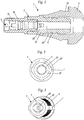
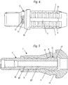
- valve 1 of snap-in type arranged to be mounted on a rim of a rubber wheel.
- Said valve 1 substantially comprises a valve body 2, also called core, an actuating mechanism 3 arranged inside said valve body 2 and a rubber ring 4 arranged for partially covering said valve body 2.
- the valve body 2 has a cylindrical shape, is axially hollow and is arranged for connecting the inside of said rubber wheels with the outside environment and allowing passage of air;
- said valve body 2 has a surface with external cylindrical symmetry 20" and a surface with internal cylindrical symmetry 20', this latter provided with a smooth portion and with a threaded portion to which said actuating mechanism 3 is screwed.
- Said valve body 2 is partially covered by a rubber ring 4 that acts as seal when the valve 1 is mounted on the wheel due to cooperation between an annular groove 13 of the rubber ring 4 and a hole made in the metal rim of the same wheel.
- the valve body 2 illustrated in Fig. 1 is composed of, i.e. it comprises, a portion, again made of plastic material 20 and a portion 30 made, in relation to specific applications, of different material, preferably metal, such as brass or aluminum, or of another type of plastic.
- the portion made of metal material 30 is the one provided with internal thread 31 for screwing of the actuating mechanism 3, while the plastic portion 20 is that arranged to be covered at least partly by said rubber ring 4.
- the internal surface 20' of said plastic portion 20 is provided with a plurality of continuous longitudinal grooves 5 arranged for increasing the section for passage of air inside said valve body 2.
- the grooves 5 are four, lobe shaped and arranged in a cross, to ensure maximum uniformity of passage of air without excessive weakening of the valve body.
- the outer surface 20" of the portion 20 of valve body arranged to be covered by the rubber ring 4 comprises a plurality of saw-edge shaped annular ribs 6.
- Said ribs 6 have the object of increasing the retaining force for said rubber ring 4 and preventing loosening between the parts during mounting of the valve 1 on the rim of the wheel.
- the same outer cylindrical surface 20" also comprises a plurality of reinforcing longitudinal ribs 7, which are superimposed on said shaped annular ribs 6.
- valves illustrated are provided with a monoblock valve body 2, made entirely of plastic material.
- Fig. 4 in particular shows four longitudinal ribs 7 arranged in a cross to ensure uniform reinforcement of the structure of the valve body 2.
- the external surface 20" of said valve body 2 made of plastic can also comprise a flat area 11 arranged for receiving markings 12, such as the manufacturer's trademark or any codes referring to the technical specifications of the product or standards of reference.
- said plastic portion 20 of said valve body 2 comprises an enlarged end 21, goblet or cup shaped, or in any case thicker in shape.
- Said end 21 is arranged for being incorporated inside said rubber ring 4.
- Said end 21 is preferably provided with a cylindrical portion 8 comprised between two frustoconical portions 9 and 10.
- the central cylindrical portion 8 corresponds to a thickening of the valve body 2, due to an increase in its thickness, very advantageous from the point of view of mechanical strength during mounting and of burst strength.
- said valve enables protective caps (not illustrated) to be screwed onto the external thread present on the front part of the main body in the same way as standard snap-in valves.
Landscapes
- Engineering & Computer Science (AREA)
- Mechanical Engineering (AREA)
- General Engineering & Computer Science (AREA)
- Check Valves (AREA)
- Valve Housings (AREA)
Claims (8)
- Ein Ventil (1) des Snap-in-Typs, das mit einer Felge von Gummireifen in Verbindung gebracht werden kann, umfassend:- einen hohlen Ventilkörper (2) zylindrischer Form, angeordnet, um das Innere des besagten Gummireifens mit der äußeren Umgebung zu verbinden und den Luftdurchgang zu erlauben;- einen Auslösemechanismus (3) des besagten Ventils (1), angeordnet im Inneren des Ventilkörpers (2);- einen entsprechend geformten Gummiring (4), angeordnet, um besagten Ventilkörper (2) teilweise zu bedecken,wobei besagter Ventilkörper (2) mindestens einen Teil (20) umfasst, der aus Plastik gemacht ist, und die Außenfläche (20") des besagten Teils (20) umfasst eine Vielzahl von geformten ringförmigen Rippen (6), um den Gummiring (4) festzuhalten, dadurch gekennzeichnet, dass die Außenfläche (20") des besagten Teils (20) mindestens eine verstärkende Längsrippe (7) umfasst, und besagte mindestens eine Längsrippe (7) auf besagter Vielzahl der geformten ringförmigen Rippen (6) aufgesetzt ist.
- Ventil (1) gemäß Anspruch 1, dadurch gekennzeichnet, dass besagter Teil (20) angeordnet ist, um von besagtem Gummiring (4) zumindest teilweise bedeckt zu werden.
- Ventil (1) gemäß Anspruch 1, dadurch gekennzeichnet, dass die Innenfläche (20') des besagten Teils (20) mit mindestens einer durchlaufenden Längsrille (5) versehen ist, angeordnet, um den Querschnitt für den Durchgang von Luft im Inneren des Ventilkörpers (2) größer zu machen.
- Ventil (1) gemäß Anspruch 1, dadurch gekennzeichnet, dass besagter Teil (20) ein geformtes dickeres Ende (21) umfasst.
- Ventil (1) gemäß Anspruch 4, dadurch gekennzeichnet, dass besagtes geformtes dickeres Ende (21) einen zylindrischen Teil (8) umfasst, der zwischen zwei kegelstumpfförmigen Teilen (9, 10) eingeschlossen ist.
- Ventil (1) gemäß Anspruch 1, dadurch gekennzeichnet, dass die Außenfläche (20") des besagten Teils (20) einen flachen Bereich (11) umfasst, angeordnet, um Kennzeichnungen (12) aufzunehmen.
- Ventil (1) gemäß Anspruch 1, dadurch gekennzeichnet, dass besagter Ventilkörper (2) mindestens einen Teil (30) umfasst, der aus Metall gemacht ist.
- Ventil (1) gemäß Anspruch 1, dadurch gekennzeichnet, dass besagter Ventilkörper (2) vollständig aus Plastik gemacht ist.
Applications Claiming Priority (2)
| Application Number | Priority Date | Filing Date | Title |
|---|---|---|---|
| IT000011A ITCR20120011A1 (it) | 2012-05-02 | 2012-05-02 | Valvola del tipo snap-in per ruote gommate |
| PCT/IT2013/000128 WO2013164866A1 (en) | 2012-05-02 | 2013-05-02 | Snap -in valve for rubber wheels |
Publications (2)
| Publication Number | Publication Date |
|---|---|
| EP2844504A1 EP2844504A1 (de) | 2015-03-11 |
| EP2844504B1 true EP2844504B1 (de) | 2019-08-07 |
Family
ID=46321230
Family Applications (1)
| Application Number | Title | Priority Date | Filing Date |
|---|---|---|---|
| EP13737432.8A Active EP2844504B1 (de) | 2012-05-02 | 2013-05-02 | Einschnappventil für gummiräder |
Country Status (5)
| Country | Link |
|---|---|
| US (1) | US9701167B2 (de) |
| EP (1) | EP2844504B1 (de) |
| CN (1) | CN104507714B (de) |
| IT (1) | ITCR20120011A1 (de) |
| WO (1) | WO2013164866A1 (de) |
Families Citing this family (4)
| Publication number | Priority date | Publication date | Assignee | Title |
|---|---|---|---|---|
| FR3066437B1 (fr) | 2017-05-16 | 2021-04-09 | Schrader | Valve de gonflage pour pneu amelioree |
| FR3072328B1 (fr) * | 2017-10-16 | 2020-03-27 | Continental Automotive France | Valve de gonflage pour jante de pneu avec limitation de deformation elastique |
| US12194791B2 (en) * | 2020-06-29 | 2025-01-14 | Christopher Cox Creative | Rapid-deflate valve stem and associated systems and methods |
| IT202100005228A1 (it) * | 2021-03-05 | 2022-09-05 | Wonder S P A | Valvola snap-in in plastica per ruote gommate |
Citations (1)
| Publication number | Priority date | Publication date | Assignee | Title |
|---|---|---|---|---|
| US4171119A (en) * | 1977-10-25 | 1979-10-16 | Lamson William C | Fluid flow valve stem |
Family Cites Families (28)
| Publication number | Priority date | Publication date | Assignee | Title |
|---|---|---|---|---|
| US1432869A (en) * | 1916-06-15 | 1922-10-24 | Henry P Kraft | Tire valve or the like |
| US1772107A (en) * | 1926-04-15 | 1930-08-05 | Safety Tire Pop Valve Company | Tire pop valve |
| US1741198A (en) * | 1927-11-02 | 1929-12-31 | Charles B Mckenna | Valve |
| US2154255A (en) * | 1937-05-15 | 1939-04-11 | Scovill Manufacturing Co | Tire valve |
| US2194850A (en) * | 1938-05-02 | 1940-03-26 | Ohio Injector Company | Pneumatic tire valve |
| US2240129A (en) * | 1939-02-15 | 1941-04-29 | Bridgeport Brass Co | Valve |
| US2312679A (en) * | 1941-10-23 | 1943-03-02 | Dill Mfg Co | Valve stem |
| US2625170A (en) * | 1950-01-07 | 1953-01-13 | Bridgeport Brass Co | Valve core for pneumatic tire valve stems |
| US3180349A (en) * | 1961-10-25 | 1965-04-27 | Bridgeport Brass Co | Tubeless tire valve |
| US3426787A (en) * | 1967-03-21 | 1969-02-11 | Leonard H Fuller | Tire valve assembly |
| US3590851A (en) * | 1968-08-06 | 1971-07-06 | Halkey Roberts Corp | Check valve |
| FR2043903A6 (de) * | 1969-05-07 | 1971-02-19 | Persenot Jean | |
| BE756526A (fr) * | 1969-09-23 | 1971-03-01 | Dunlop Co Ltd | Perfectionnements aux valves de gonflage |
| US3610269A (en) * | 1970-04-22 | 1971-10-05 | Diamond U Products Inc | Pressure gauge and valve for a tire |
| US3906988A (en) * | 1974-06-18 | 1975-09-23 | Nat Distillers Chem Corp | Combined valve and pressure indicator for pneumatic tires |
| US4072048A (en) * | 1976-04-01 | 1978-02-07 | John Arvan | Indicating apparatus for measuring the pressure of a fluid within a container |
| AU6606781A (en) * | 1981-01-08 | 1982-07-15 | Kyung Dong, L | Air valve for pneumatic tyres |
| US4481970A (en) * | 1982-06-10 | 1984-11-13 | Jack H. Zabel, Jr. | Tire valve |
| IT1153281B (it) * | 1982-10-21 | 1987-01-14 | Bridgeport Brass Spa | Parte interna migliorata per valvola atta ad essere applicata su articoli pneumatici |
| US4538658A (en) * | 1983-01-17 | 1985-09-03 | Bridge Products, Inc. | Tire valve assembly |
| US4506695A (en) * | 1983-04-04 | 1985-03-26 | Scovill Inc. | Plastic tire valve |
| DE3623837A1 (de) * | 1985-07-24 | 1987-02-26 | Alligator Ventilfab Gmbh | Ventil insbesondere fuer einen fahrradschlauch |
| US5027848A (en) * | 1989-12-05 | 1991-07-02 | Leeuwen Johannes V | Pressure indicating valve stem |
| US5060685A (en) * | 1990-10-18 | 1991-10-29 | Ilya Zhabokrug | Safety cap for tire valve |
| DE69427233D1 (de) * | 1993-10-08 | 2001-06-21 | Ludowici J C & Son Ltd | Reifenventil mit Druckanzeige |
| US20050000568A1 (en) * | 2003-04-29 | 2005-01-06 | Ilya Nikolayev | Rapid access coupling system for pneumatic tires |
| US20050028865A1 (en) * | 2003-08-05 | 2005-02-10 | Ilya Nikolayev | Rapid access tire valve for a pneumatic tire on a rim of a vehicle and connector therefor |
| US7624752B2 (en) * | 2006-11-22 | 2009-12-01 | Tien-Tsai Huang | Inflation valve |
-
2012
- 2012-05-02 IT IT000011A patent/ITCR20120011A1/it unknown
-
2013
- 2013-05-02 WO PCT/IT2013/000128 patent/WO2013164866A1/en not_active Ceased
- 2013-05-02 CN CN201380029768.5A patent/CN104507714B/zh not_active Expired - Fee Related
- 2013-05-02 US US14/397,927 patent/US9701167B2/en not_active Expired - Fee Related
- 2013-05-02 EP EP13737432.8A patent/EP2844504B1/de active Active
Patent Citations (1)
| Publication number | Priority date | Publication date | Assignee | Title |
|---|---|---|---|---|
| US4171119A (en) * | 1977-10-25 | 1979-10-16 | Lamson William C | Fluid flow valve stem |
Also Published As
| Publication number | Publication date |
|---|---|
| EP2844504A1 (de) | 2015-03-11 |
| CN104507714A (zh) | 2015-04-08 |
| ITCR20120011A1 (it) | 2013-11-03 |
| WO2013164866A1 (en) | 2013-11-07 |
| US20150122348A1 (en) | 2015-05-07 |
| US9701167B2 (en) | 2017-07-11 |
| CN104507714B (zh) | 2017-07-18 |
Similar Documents
| Publication | Publication Date | Title |
|---|---|---|
| KR101137813B1 (ko) | 타이어 압력 모니터링 시스템 및 그의 타이어센서 | |
| US9701167B2 (en) | Snap-in valve for rubber wheels | |
| US10399381B2 (en) | Non-pneumatic tire | |
| US4538658A (en) | Tire valve assembly | |
| US20040119584A1 (en) | Transmitter in tire condition monitoring apparatus | |
| US20160001608A1 (en) | Sidewall decoration on rim guard | |
| US20170368877A1 (en) | Non-pneumatic tire with integrated polymeric flexible wheel center mount | |
| US9744819B2 (en) | Metal valve of the clamp-in type for inflating tyres associable with a TPMS transducer | |
| US20040021368A1 (en) | Rim for a bicycle wheel with tubeless tire | |
| US7726370B2 (en) | Vehicle wheel comprising a wheel rim and rubber tire | |
| US20200070600A1 (en) | Improved inflation valve for tyre | |
| KR20140051380A (ko) | 전자 모듈 및 팽창 밸브를 포함하는, 차량 휠의 작동 매개변수를 측정하기 위한 전자 유닛 | |
| US5593520A (en) | Ring device for running on a flat tire | |
| US20110272038A1 (en) | Adapter incorporating TPMS onto a truck valve | |
| US10279621B2 (en) | Vehicle wheel | |
| EP3902690B1 (de) | Luftloser reifen mit verstärkter trägerstruktur | |
| JP2017100588A (ja) | 非空気入りタイヤおよび非空気入りタイヤの製造方法 | |
| EP4052933A1 (de) | Steckventil aus kunststoff für gummierte räder | |
| US20170361668A1 (en) | Air maintenance tire system component protector | |
| US8122927B2 (en) | Inner-tube assembly for bicycle wheel | |
| CN103038073B (zh) | 用于阀杆的帽 | |
| KR20180037119A (ko) | 공기 유지 타이어용 연결 부재 및 이를 형성하는 방법 | |
| KR200489733Y1 (ko) | 센서결합부가 형성된 타이어 | |
| EP3318429A1 (de) | Reifen mit pneumatischer wartung | |
| CN219903951U (zh) | 一种防止传感器脱落的胎压监测气门嘴 |
Legal Events
| Date | Code | Title | Description |
|---|---|---|---|
| PUAI | Public reference made under article 153(3) epc to a published international application that has entered the european phase |
Free format text: ORIGINAL CODE: 0009012 |
|
| 17P | Request for examination filed |
Effective date: 20141118 |
|
| AK | Designated contracting states |
Kind code of ref document: A1 Designated state(s): AL AT BE BG CH CY CZ DE DK EE ES FI FR GB GR HR HU IE IS IT LI LT LU LV MC MK MT NL NO PL PT RO RS SE SI SK SM TR |
|
| AX | Request for extension of the european patent |
Extension state: BA ME |
|
| DAX | Request for extension of the european patent (deleted) | ||
| STAA | Information on the status of an ep patent application or granted ep patent |
Free format text: STATUS: EXAMINATION IS IN PROGRESS |
|
| 17Q | First examination report despatched |
Effective date: 20180608 |
|
| REG | Reference to a national code |
Ref country code: DE Ref legal event code: R079 Ref document number: 602013058796 Country of ref document: DE Free format text: PREVIOUS MAIN CLASS: B60C0029000000 Ipc: F16K0015200000 |
|
| RIC1 | Information provided on ipc code assigned before grant |
Ipc: B60C 29/02 20060101ALI20190114BHEP Ipc: B60C 29/00 20060101ALI20190114BHEP Ipc: F16K 15/20 20060101AFI20190114BHEP |
|
| GRAP | Despatch of communication of intention to grant a patent |
Free format text: ORIGINAL CODE: EPIDOSNIGR1 |
|
| STAA | Information on the status of an ep patent application or granted ep patent |
Free format text: STATUS: GRANT OF PATENT IS INTENDED |
|
| INTG | Intention to grant announced |
Effective date: 20190226 |
|
| GRAS | Grant fee paid |
Free format text: ORIGINAL CODE: EPIDOSNIGR3 |
|
| GRAA | (expected) grant |
Free format text: ORIGINAL CODE: 0009210 |
|
| STAA | Information on the status of an ep patent application or granted ep patent |
Free format text: STATUS: THE PATENT HAS BEEN GRANTED |
|
| AK | Designated contracting states |
Kind code of ref document: B1 Designated state(s): AL AT BE BG CH CY CZ DE DK EE ES FI FR GB GR HR HU IE IS IT LI LT LU LV MC MK MT NL NO PL PT RO RS SE SI SK SM TR |
|
| REG | Reference to a national code |
Ref country code: GB Ref legal event code: FG4D |
|
| REG | Reference to a national code |
Ref country code: CH Ref legal event code: EP Ref country code: AT Ref legal event code: REF Ref document number: 1164402 Country of ref document: AT Kind code of ref document: T Effective date: 20190815 |
|
| REG | Reference to a national code |
Ref country code: DE Ref legal event code: R096 Ref document number: 602013058796 Country of ref document: DE |
|
| REG | Reference to a national code |
Ref country code: IE Ref legal event code: FG4D |
|
| REG | Reference to a national code |
Ref country code: NL Ref legal event code: MP Effective date: 20190807 |
|
| REG | Reference to a national code |
Ref country code: LT Ref legal event code: MG4D |
|
| PG25 | Lapsed in a contracting state [announced via postgrant information from national office to epo] |
Ref country code: SE Free format text: LAPSE BECAUSE OF FAILURE TO SUBMIT A TRANSLATION OF THE DESCRIPTION OR TO PAY THE FEE WITHIN THE PRESCRIBED TIME-LIMIT Effective date: 20190807 Ref country code: BG Free format text: LAPSE BECAUSE OF FAILURE TO SUBMIT A TRANSLATION OF THE DESCRIPTION OR TO PAY THE FEE WITHIN THE PRESCRIBED TIME-LIMIT Effective date: 20191107 Ref country code: NL Free format text: LAPSE BECAUSE OF FAILURE TO SUBMIT A TRANSLATION OF THE DESCRIPTION OR TO PAY THE FEE WITHIN THE PRESCRIBED TIME-LIMIT Effective date: 20190807 Ref country code: LT Free format text: LAPSE BECAUSE OF FAILURE TO SUBMIT A TRANSLATION OF THE DESCRIPTION OR TO PAY THE FEE WITHIN THE PRESCRIBED TIME-LIMIT Effective date: 20190807 Ref country code: HR Free format text: LAPSE BECAUSE OF FAILURE TO SUBMIT A TRANSLATION OF THE DESCRIPTION OR TO PAY THE FEE WITHIN THE PRESCRIBED TIME-LIMIT Effective date: 20190807 Ref country code: PT Free format text: LAPSE BECAUSE OF FAILURE TO SUBMIT A TRANSLATION OF THE DESCRIPTION OR TO PAY THE FEE WITHIN THE PRESCRIBED TIME-LIMIT Effective date: 20191209 Ref country code: FI Free format text: LAPSE BECAUSE OF FAILURE TO SUBMIT A TRANSLATION OF THE DESCRIPTION OR TO PAY THE FEE WITHIN THE PRESCRIBED TIME-LIMIT Effective date: 20190807 Ref country code: NO Free format text: LAPSE BECAUSE OF FAILURE TO SUBMIT A TRANSLATION OF THE DESCRIPTION OR TO PAY THE FEE WITHIN THE PRESCRIBED TIME-LIMIT Effective date: 20191107 |
|
| REG | Reference to a national code |
Ref country code: AT Ref legal event code: MK05 Ref document number: 1164402 Country of ref document: AT Kind code of ref document: T Effective date: 20190807 |
|
| PG25 | Lapsed in a contracting state [announced via postgrant information from national office to epo] |
Ref country code: LV Free format text: LAPSE BECAUSE OF FAILURE TO SUBMIT A TRANSLATION OF THE DESCRIPTION OR TO PAY THE FEE WITHIN THE PRESCRIBED TIME-LIMIT Effective date: 20190807 Ref country code: GR Free format text: LAPSE BECAUSE OF FAILURE TO SUBMIT A TRANSLATION OF THE DESCRIPTION OR TO PAY THE FEE WITHIN THE PRESCRIBED TIME-LIMIT Effective date: 20191108 Ref country code: IS Free format text: LAPSE BECAUSE OF FAILURE TO SUBMIT A TRANSLATION OF THE DESCRIPTION OR TO PAY THE FEE WITHIN THE PRESCRIBED TIME-LIMIT Effective date: 20191207 Ref country code: ES Free format text: LAPSE BECAUSE OF FAILURE TO SUBMIT A TRANSLATION OF THE DESCRIPTION OR TO PAY THE FEE WITHIN THE PRESCRIBED TIME-LIMIT Effective date: 20190807 Ref country code: AL Free format text: LAPSE BECAUSE OF FAILURE TO SUBMIT A TRANSLATION OF THE DESCRIPTION OR TO PAY THE FEE WITHIN THE PRESCRIBED TIME-LIMIT Effective date: 20190807 Ref country code: RS Free format text: LAPSE BECAUSE OF FAILURE TO SUBMIT A TRANSLATION OF THE DESCRIPTION OR TO PAY THE FEE WITHIN THE PRESCRIBED TIME-LIMIT Effective date: 20190807 |
|
| PG25 | Lapsed in a contracting state [announced via postgrant information from national office to epo] |
Ref country code: TR Free format text: LAPSE BECAUSE OF FAILURE TO SUBMIT A TRANSLATION OF THE DESCRIPTION OR TO PAY THE FEE WITHIN THE PRESCRIBED TIME-LIMIT Effective date: 20190807 |
|
| PG25 | Lapsed in a contracting state [announced via postgrant information from national office to epo] |
Ref country code: AT Free format text: LAPSE BECAUSE OF FAILURE TO SUBMIT A TRANSLATION OF THE DESCRIPTION OR TO PAY THE FEE WITHIN THE PRESCRIBED TIME-LIMIT Effective date: 20190807 Ref country code: RO Free format text: LAPSE BECAUSE OF FAILURE TO SUBMIT A TRANSLATION OF THE DESCRIPTION OR TO PAY THE FEE WITHIN THE PRESCRIBED TIME-LIMIT Effective date: 20190807 Ref country code: EE Free format text: LAPSE BECAUSE OF FAILURE TO SUBMIT A TRANSLATION OF THE DESCRIPTION OR TO PAY THE FEE WITHIN THE PRESCRIBED TIME-LIMIT Effective date: 20190807 Ref country code: PL Free format text: LAPSE BECAUSE OF FAILURE TO SUBMIT A TRANSLATION OF THE DESCRIPTION OR TO PAY THE FEE WITHIN THE PRESCRIBED TIME-LIMIT Effective date: 20190807 Ref country code: DK Free format text: LAPSE BECAUSE OF FAILURE TO SUBMIT A TRANSLATION OF THE DESCRIPTION OR TO PAY THE FEE WITHIN THE PRESCRIBED TIME-LIMIT Effective date: 20190807 |
|
| PG25 | Lapsed in a contracting state [announced via postgrant information from national office to epo] |
Ref country code: SM Free format text: LAPSE BECAUSE OF FAILURE TO SUBMIT A TRANSLATION OF THE DESCRIPTION OR TO PAY THE FEE WITHIN THE PRESCRIBED TIME-LIMIT Effective date: 20190807 Ref country code: SK Free format text: LAPSE BECAUSE OF FAILURE TO SUBMIT A TRANSLATION OF THE DESCRIPTION OR TO PAY THE FEE WITHIN THE PRESCRIBED TIME-LIMIT Effective date: 20190807 Ref country code: IS Free format text: LAPSE BECAUSE OF FAILURE TO SUBMIT A TRANSLATION OF THE DESCRIPTION OR TO PAY THE FEE WITHIN THE PRESCRIBED TIME-LIMIT Effective date: 20200224 Ref country code: CZ Free format text: LAPSE BECAUSE OF FAILURE TO SUBMIT A TRANSLATION OF THE DESCRIPTION OR TO PAY THE FEE WITHIN THE PRESCRIBED TIME-LIMIT Effective date: 20190807 |
|
| REG | Reference to a national code |
Ref country code: DE Ref legal event code: R097 Ref document number: 602013058796 Country of ref document: DE |
|
| PLBE | No opposition filed within time limit |
Free format text: ORIGINAL CODE: 0009261 |
|
| STAA | Information on the status of an ep patent application or granted ep patent |
Free format text: STATUS: NO OPPOSITION FILED WITHIN TIME LIMIT |
|
| PG2D | Information on lapse in contracting state deleted |
Ref country code: IS |
|
| 26N | No opposition filed |
Effective date: 20200603 |
|
| PG25 | Lapsed in a contracting state [announced via postgrant information from national office to epo] |
Ref country code: SI Free format text: LAPSE BECAUSE OF FAILURE TO SUBMIT A TRANSLATION OF THE DESCRIPTION OR TO PAY THE FEE WITHIN THE PRESCRIBED TIME-LIMIT Effective date: 20190807 |
|
| PG25 | Lapsed in a contracting state [announced via postgrant information from national office to epo] |
Ref country code: MC Free format text: LAPSE BECAUSE OF FAILURE TO SUBMIT A TRANSLATION OF THE DESCRIPTION OR TO PAY THE FEE WITHIN THE PRESCRIBED TIME-LIMIT Effective date: 20190807 Ref country code: CH Free format text: LAPSE BECAUSE OF NON-PAYMENT OF DUE FEES Effective date: 20200531 Ref country code: LI Free format text: LAPSE BECAUSE OF NON-PAYMENT OF DUE FEES Effective date: 20200531 |
|
| REG | Reference to a national code |
Ref country code: BE Ref legal event code: MM Effective date: 20200531 |
|
| GBPC | Gb: european patent ceased through non-payment of renewal fee |
Effective date: 20200502 |
|
| PG25 | Lapsed in a contracting state [announced via postgrant information from national office to epo] |
Ref country code: LU Free format text: LAPSE BECAUSE OF NON-PAYMENT OF DUE FEES Effective date: 20200502 |
|
| PG25 | Lapsed in a contracting state [announced via postgrant information from national office to epo] |
Ref country code: IE Free format text: LAPSE BECAUSE OF NON-PAYMENT OF DUE FEES Effective date: 20200502 Ref country code: GB Free format text: LAPSE BECAUSE OF NON-PAYMENT OF DUE FEES Effective date: 20200502 |
|
| PG25 | Lapsed in a contracting state [announced via postgrant information from national office to epo] |
Ref country code: BE Free format text: LAPSE BECAUSE OF NON-PAYMENT OF DUE FEES Effective date: 20200531 |
|
| PG25 | Lapsed in a contracting state [announced via postgrant information from national office to epo] |
Ref country code: MT Free format text: LAPSE BECAUSE OF FAILURE TO SUBMIT A TRANSLATION OF THE DESCRIPTION OR TO PAY THE FEE WITHIN THE PRESCRIBED TIME-LIMIT Effective date: 20190807 Ref country code: CY Free format text: LAPSE BECAUSE OF FAILURE TO SUBMIT A TRANSLATION OF THE DESCRIPTION OR TO PAY THE FEE WITHIN THE PRESCRIBED TIME-LIMIT Effective date: 20190807 |
|
| PG25 | Lapsed in a contracting state [announced via postgrant information from national office to epo] |
Ref country code: MK Free format text: LAPSE BECAUSE OF FAILURE TO SUBMIT A TRANSLATION OF THE DESCRIPTION OR TO PAY THE FEE WITHIN THE PRESCRIBED TIME-LIMIT Effective date: 20190807 |
|
| PGFP | Annual fee paid to national office [announced via postgrant information from national office to epo] |
Ref country code: IT Payment date: 20230419 Year of fee payment: 11 Ref country code: FR Payment date: 20230526 Year of fee payment: 11 Ref country code: DE Payment date: 20230530 Year of fee payment: 11 |
|
| P01 | Opt-out of the competence of the unified patent court (upc) registered |
Effective date: 20230731 |
|
| REG | Reference to a national code |
Ref country code: DE Ref legal event code: R119 Ref document number: 602013058796 Country of ref document: DE |
|
| PG25 | Lapsed in a contracting state [announced via postgrant information from national office to epo] |
Ref country code: DE Free format text: LAPSE BECAUSE OF NON-PAYMENT OF DUE FEES Effective date: 20241203 |
|
| PG25 | Lapsed in a contracting state [announced via postgrant information from national office to epo] |
Ref country code: FR Free format text: LAPSE BECAUSE OF NON-PAYMENT OF DUE FEES Effective date: 20240531 |
|
| PG25 | Lapsed in a contracting state [announced via postgrant information from national office to epo] |
Ref country code: IT Free format text: LAPSE BECAUSE OF NON-PAYMENT OF DUE FEES Effective date: 20240502 |