EP2844452B1 - Superharte komponenten für spritzgussformen - Google Patents
Superharte komponenten für spritzgussformen Download PDFInfo
- Publication number
- EP2844452B1 EP2844452B1 EP13723609.7A EP13723609A EP2844452B1 EP 2844452 B1 EP2844452 B1 EP 2844452B1 EP 13723609 A EP13723609 A EP 13723609A EP 2844452 B1 EP2844452 B1 EP 2844452B1
- Authority
- EP
- European Patent Office
- Prior art keywords
- injection mold
- wear
- injection
- resistant surface
- superhard material
- Prior art date
- Legal status (The legal status is an assumption and is not a legal conclusion. Google has not performed a legal analysis and makes no representation as to the accuracy of the status listed.)
- Active
Links
Images






Classifications
-
- B—PERFORMING OPERATIONS; TRANSPORTING
- B29—WORKING OF PLASTICS; WORKING OF SUBSTANCES IN A PLASTIC STATE IN GENERAL
- B29C—SHAPING OR JOINING OF PLASTICS; SHAPING OF MATERIAL IN A PLASTIC STATE, NOT OTHERWISE PROVIDED FOR; AFTER-TREATMENT OF THE SHAPED PRODUCTS, e.g. REPAIRING
- B29C45/00—Injection moulding, i.e. forcing the required volume of moulding material through a nozzle into a closed mould; Apparatus therefor
- B29C45/17—Component parts, details or accessories; Auxiliary operations
- B29C45/40—Removing or ejecting moulded articles
-
- B—PERFORMING OPERATIONS; TRANSPORTING
- B29—WORKING OF PLASTICS; WORKING OF SUBSTANCES IN A PLASTIC STATE IN GENERAL
- B29C—SHAPING OR JOINING OF PLASTICS; SHAPING OF MATERIAL IN A PLASTIC STATE, NOT OTHERWISE PROVIDED FOR; AFTER-TREATMENT OF THE SHAPED PRODUCTS, e.g. REPAIRING
- B29C33/00—Moulds or cores; Details thereof or accessories therefor
- B29C33/38—Moulds or cores; Details thereof or accessories therefor characterised by the material or the manufacturing process
-
- B—PERFORMING OPERATIONS; TRANSPORTING
- B29—WORKING OF PLASTICS; WORKING OF SUBSTANCES IN A PLASTIC STATE IN GENERAL
- B29K—INDEXING SCHEME ASSOCIATED WITH SUBCLASSES B29B, B29C OR B29D, RELATING TO MOULDING MATERIALS OR TO MATERIALS FOR MOULDS, REINFORCEMENTS, FILLERS OR PREFORMED PARTS, e.g. INSERTS
- B29K2907/00—Use of elements other than metals as mould material
-
- B—PERFORMING OPERATIONS; TRANSPORTING
- B29—WORKING OF PLASTICS; WORKING OF SUBSTANCES IN A PLASTIC STATE IN GENERAL
- B29K—INDEXING SCHEME ASSOCIATED WITH SUBCLASSES B29B, B29C OR B29D, RELATING TO MOULDING MATERIALS OR TO MATERIALS FOR MOULDS, REINFORCEMENTS, FILLERS OR PREFORMED PARTS, e.g. INSERTS
- B29K2907/00—Use of elements other than metals as mould material
- B29K2907/02—Boron
-
- B—PERFORMING OPERATIONS; TRANSPORTING
- B29—WORKING OF PLASTICS; WORKING OF SUBSTANCES IN A PLASTIC STATE IN GENERAL
- B29K—INDEXING SCHEME ASSOCIATED WITH SUBCLASSES B29B, B29C OR B29D, RELATING TO MOULDING MATERIALS OR TO MATERIALS FOR MOULDS, REINFORCEMENTS, FILLERS OR PREFORMED PARTS, e.g. INSERTS
- B29K2907/00—Use of elements other than metals as mould material
- B29K2907/04—Carbon
-
- B—PERFORMING OPERATIONS; TRANSPORTING
- B29—WORKING OF PLASTICS; WORKING OF SUBSTANCES IN A PLASTIC STATE IN GENERAL
- B29K—INDEXING SCHEME ASSOCIATED WITH SUBCLASSES B29B, B29C OR B29D, RELATING TO MOULDING MATERIALS OR TO MATERIALS FOR MOULDS, REINFORCEMENTS, FILLERS OR PREFORMED PARTS, e.g. INSERTS
- B29K2995/00—Properties of moulding materials, reinforcements, fillers, preformed parts or moulds
- B29K2995/0037—Other properties
- B29K2995/007—Hardness
-
- B—PERFORMING OPERATIONS; TRANSPORTING
- B29—WORKING OF PLASTICS; WORKING OF SUBSTANCES IN A PLASTIC STATE IN GENERAL
- B29K—INDEXING SCHEME ASSOCIATED WITH SUBCLASSES B29B, B29C OR B29D, RELATING TO MOULDING MATERIALS OR TO MATERIALS FOR MOULDS, REINFORCEMENTS, FILLERS OR PREFORMED PARTS, e.g. INSERTS
- B29K2995/00—Properties of moulding materials, reinforcements, fillers, preformed parts or moulds
- B29K2995/0037—Other properties
- B29K2995/0087—Wear resistance
Definitions
- injection molding processes have relatively widespread use and may be employed to produce a wide variety of parts. For instance, injection molded parts may range from only a few millimeters in size to parts that are several meters wide. Injection molding also may be used produce components that have various geometries, complexity of which may vary from simple to highly intricate in detail. Furthermore, injection molding processes may produce parts from various materials, including but not limited to thermoplastic polymers, aluminum alloys, zinc alloys, etc.
- injection molding is most commonly used to manufacture parts in large quantities. This may allow the cost of the injection mold to be amortized over thousands or even hundreds of thousands of molded parts.
- Typical molds are constructed from metallic materials, such as steel, aluminum, brass, copper, etc. Usability of the mold may vary based on the materials used therein. For example, use of softer and/or less wear-resistant metals, which may exhibit increased wear in an injection mold, may lead to unusable parts produced by the mold. Ordinarily, material wear results from "cycling" the mold- i . e ., closing the mold, injecting molten molding material, opening the mold, and/or ejecting or removing the parts. The rate and/or amount of wear may depend on the part geometry, molding material used in the process, frequency and number of cycles, and other factors present during the operation of the mold.
- an injection mold may include certain components that may exhibit more wear than other components, due to the nature of the operation of the mold. Thus, in some instances, a typical mold may require repair or replacement where increased wear may lead to failure of such components.
- the invention is directed to an injection mold component in accordance with claim 1 for use in an injection mold, the injection mold component being an ejector sleeve.
- the injection mold component being an ejector sleeve.
- Various embodiments of the invention are directed to ejections sleeves that comprise a superhard material, as well as injection molding system that may utilize such ejection sleeves.
- Superhard materials may be arranged and formed in any number of sizes and configurations. In some embodiments, superhard materials may be available in limited sizes. Hence, multiple segments may be used to enable forming desired surface sizes and configurations, notwithstanding possible limitations in the size of available superhard materials.
- Superhard materials also may be located along all or portion of one or more surfaces of the injection mold component, to form one or more wear-resistant surface, which may provide increased resistance to wear for such surfaces of the injection mold component.
- the injection molding machine may inject, for example, molten thermoplastics, thermosets, elastomers, aluminum alloys, and zinc alloys into an injection mold, to manufacture various parts from such materials or combinations thereof.
- the injection molding machine may inject thermoplastics, thermosets, elastomers, or combinations thereof that incorporate metallic powder, thereby producing a "green" part, which may allow the manufacturer to make metal parts by removing the polymer material from the "green part” and sintering the metallic powder.
- FIG. 1 illustrates an injection molding system 100, which may include an injection molding machine 110 and an injection mold 120 (shown in a closed position). Although the particular configuration or operation of the injection molding machine 110 may vary in some regards with respect to other available machines or processes, the injection molding machine 110 may be a typical machine used for manufacturing injection molded parts.
- the injection molding machine 110 may include a front platen 111 and a back platen 112.
- the back platen 112 may move with respect to the front platen 111, which may cause the injection mold 120 to open.
- the injection mold 120 may have a stationary portion 121 and a moving portion 122, which may define a parting line 123 ( i.e., the line (or one or more planes) along which the injection mold 120 splits to open).
- the stationary portion 121 of the injection mold 120 may be secured to the front platen 111 and the moving portion 122 may be secured to the back platen 112.
- movement of the back platen 112 in a direction away from the front platen 111 may cause the moving portion 122 of the injection mold 120 to move away from the stationary portion 121, thereby opening the injection mold 120 along the parting line 123.
- movement of the back platen 112 toward the front platen 111 may cause the injection mold 120 to close.
- the injection molding machine 110 also may include a material hopper 113 and an injection system 114, which may supply molten molding material into the injection mold 120. More particularly, molding material (e.g ., plastic pellets) may be added into the material hopper 113 and fed into the injection system 114.
- the injection system 114 may include a screw 115 that may rotate within a barrel.
- one or more heaters 116 may surround the barrel to heat and/or at least partially or completely melt the molding material.
- the melted molding material may be conveyed by the screw 115, which may be a reciprocating screw, toward the injection mold 120.
- the molten molding material may be injected into the injection mold 120 through an injection nozzle 117.
- the injection system 114 may include a plunger, which may replace or may be incorporated into the screw 115, and which may inject the molten molding material into the injection mold 120.
- molten molding material may be injected into the injection mold 120. More specifically, the molten material may fill a molding volume 131 within the injection mold 120. Subsequently, as shown in FIG. 2 , the molten molding material may cool and at least partially solidify to form a part corresponding to the molding volume 131. When the molten molding material forming the part has cooled to a desired temperature, the injection mold 120 may be opened, by moving the back platen 112 away from the front platen 111 (as described above), and the part may be ejected or removed from the injection mold 120.
- the injection mold 120 may incorporate various molding elements, which may have necessary shapes and sizes to form a part 130.
- the injection mold 120 may include one or more molding elements 140, such as molding elements 140a, 140b, 140c (which may include a cavity, a core, a core pin, core inserts, etc.) that assemble to define the molding volume 131.
- a "molding element” refers to any portion of the injection mold 120 that forms at least a portion of the part 130 ( i.e., portion(s) of the injection mold 120 that define the molding volume 131).
- the injection mold 120 may include multiple sets of molding elements 140, which may be substantially identical (to produce the same parts) or may vary, for production of different parts in the single cycle.
- a "set of molding elements” refers to the molding elements 140 that, when combined, form or define the molding volume 131 ( see FIG. 1 ), which may accept molten material and form the part 130.
- the injection mold 120 may be secured in the injection molding machine 110. More specifically, the injection mold 120 may be secured to the front platen 111 and back platen 112.
- the nonmoving portion 121 of the injection mold 120 may have one or more clamping grooves that may accommodate clamps for securing the nonmoving portion 121 to the front platen 111 of the injection molding machine 110.
- the nonmoving portion 121 may include one or more plates, such as a first plate 121a and a top clamping plate 121b, which may form such clamping grooves.
- the nonmoving portion 121 also may include an overhang that may accommodate clamps, bolt holes that may accept bolts for securing the nonmoving portion 121 to the front platen 111, and/or other features that may be used to secure the nonmoving portion 121 to the front platen 111, which should be appreciated by those skilled in the art.
- the nonmoving portion 121 also may include a sprue bushing 150, which may channel the molten molding material into the injection mold 120.
- the injection nozzle 117 may have a spherical tip which may contact a sphere of the same or similar radius on the sprue bushing 150. Subsequently, the molten molding material may flow from the injection system 114 of the injection molding machine 110, through the injection nozzle 117, through the sprue bushing 150, and into the injection mold 120.
- the nonmoving portion 121 also may include a locating ring 160, which may aid in aligning the injection mold 120 and/or the sprue bushing 150 with the injection molding machine 110 as well as with the injection nozzle 117.
- the moving portion 122 of the injection mold 120 may be connected to the back platen 112 of the injection molding machine 110. Similar to the nonmoving portion 121, the moving portion 122 may incorporate a clamping groove or other features that may allow the manufacturer to connect the moving portion 122 of the injection mold 120 to the back platen 112 of the injection molding machine 110. Furthermore, the moving portion 122 may include a second plate 122a that may secure or incorporate the molding element 140b. The moving portion 122 of the injection mold 120 also may include a support plate 122b, which may provide support to the second plate 122a and additional rigidity to the injection mold 120.
- the moving portion 122 and the nonmoving portion 121 of the injection mold 120 may include leader pins and corresponding bushings (not shown), which may aid in aligning the moving portion 122 and the nonmoving portion 121 during the opening and closing of the injection mold 120.
- the injection mold 120 may include interlock pairs 280, which may comprise male and corresponding female interlock portions.
- clearance between the male and the corresponding female interlock portions may be substantially smaller than the clearance between the leader pins and corresponding bushings.
- the clearance between the male and female interlocks may be in the range of 0.0002 inch to 0.0005 inch per side.
- the injection mold 120 also may incorporate an ejection mechanism, which may eject the part 130 after the part 130 has cooled down to a desired temperature.
- the ejection mechanism may include an ejector housing 122c and ejector plates 122d.
- the ejector plates 122d may connect to an ejection system of the injection molding machine 110, which may move the ejector plates 122d toward the front platen 111.
- the ejector plates 122d may secure one or more ejector pins 170, which may move together with the ejector plates 122d and eject the part 130 out of the injection mold 120.
- the injection mold 120 also may incorporate one or more ejector sleeves, such as ejector sleeves 220a, 220b. More particularly, the ejector sleeve 220a may guide the ejector pin 170 through the molding element 140b. Hence, a portion ( e.g., a top surface) of the ejector sleeve 220a may contact the part 130 and may at least in part form the molding volume 131.
- a core pin 140c may be secured in the ejector housing 122c.
- the core pin 140c may at least in part define the molding volume 131 (e.g., the core pin 140c may form a hole in the part 130).
- the ejector sleeve 122b may provide additional uniformity during ejection of the part 130. More specifically, the ejector plates 122d also may secure one or more ejector sleeves, such as the ejector sleeve 122b, which may slide about the core pin 140b, thereby aiding in ejection of the part 130.
- the injection mold 120 may include all, some, and/or additional molding elements, plates, and/or devices described herein.
- the injection mold 120 may have no ejector housing or ejector plates, and the manufacturer may choose to remove the parts with a robotic arm (or manually) to avoid ejector pin marks on the parts.
- the injection mold 120 may also include additional plates and/or devices, not described herein, which may be necessary for operation.
- the manufacturer may choose to use a stripper plate (where applicable), which may strip the part 130 from the molding element 140b.
- components described herein may be used in the injection mold 120 of any configuration or design.
- the part 130 may include undercuts or undercutting portions, which may need to be relieved before the part 130 may be ejected from the injection mold 120.
- one or more slides or lifters may be used to relieve undercuts and allow the part 130 to be ejected, as described in more detail below.
- a slide may move substantially orthogonally with respect to the undercut, thereby removing at least a portion of the molding element 140 away from the part 130.
- a lifter may move in a direction of ejection ( i.e ., toward the front platen 111) and orthogonally to the undercut-thus, ejecting the part while relieving the undercut.
- one or more surfaces of one or more components comprising the injection mold 120 may include one or more layers of superhard material. More particularly, one or more layers of superhard material may form one or more wear-resistant surfaces on the injection mold components.
- An "injection mold component” refers to any component and/or element comprising an injection mold.
- the term “superhard,” or the phrase “superhard material,” refers to any material having a hardness that is at least equal to the hardness of tungsten carbide.
- element numbers denoted with letters "sm” identify superhard material in particular embodiments. It should be noted that so denoted superhard material may be any superhard material disclosed herein.
- element numbers denoted with letters "wr” identify wear-resistant surface that may be formed by one or more layers of superhard material on a particular injection mold component.
- one or more substrates may be bonded to the injection mold components.
- the substrates may be a cobalt-cemented tungsten carbide substrate or other carbide substrate.
- the layer of superhard material forming the wear-resistant surface may be natural diamond, polycrystalline diamond, polycrystalline cubic boron nitride, silicon carbide, diamond grains bonded together with silicon carbide, or any combination of the preceding materials.
- the superhard material may be thermally-stable diamond in which a catalyst material (e.g ., iron, nickel, cobalt, or alloys thereof) has been at least partially depleted from a surface or volume of the polycrystalline diamond using, for example, a leaching process.
- a cemented carbide substrate may comprise any suitable carbide, such as tungsten carbide, tantalum carbide, vanadium carbide, niobium carbide, chromium carbide, titanium carbide, or combinations of the foregoing carbides.
- the superhard material includes one or more polycrystalline diamond compacts (PDCs).
- the substrate may comprise cobalt-cemented tungsten carbide and the layer of superhard material may include polycrystalline diamond.
- PDCs polycrystalline diamond compacts
- Such structures may be fabricated by subjecting diamond particles, placed on or proximate to a cobalt-cemented tungsten carbide substrate, to a high-pressure/high-temperature (HPHT) sintering process.
- HPHT high-pressure/high-temperature
- the diamond particles with the cobalt-cemented tungsten carbide substrate may be HPHT sintered at a temperature of at least about 1000° Celsius (e.g ., about 1100°C to about 1600°C) and a pressure of at least about 4 GPa ( e.g ., about 5 GPa to about 9 GPa) for a time sufficient to consolidate and form a coherent mass of bonded diamond grains.
- the cobalt from the cobalt-cemented tungsten carbide substrate sweeps into interstitial regions between the diamond particles to catalyze growth of diamond between the diamond particles.
- the superhard material may comprise a matrix of diamond grains that are bonded with each other via diamond-to-diamond bonding (e.g ., sp 3 bonding), and the interstitial regions between the diamond grains may be at least partially occupied by cobalt or another catalyst, thereby creating a network of diamond grains with interposed cobalt or other catalyst, otherwise known as polycrystalline diamond (PCD).
- PCD polycrystalline diamond
- the catalyst used for forming the PCD superhard material may be a metal-solvent catalyst, such as cobalt, nickel, iron, or alloys thereof.
- a thermal stability of such PCD superhard material may be improved by leaching the metal-solvent catalyst from of the PCD. Leaching may be performed in a suitable acid, such as aqua regia, nitric acid, hydrofluoric acid, or combination thereof, so that the leach PCD superhard material is substantially free of metal-solvent catalyst.
- the PCD superhard material may be entirely or partially. Generally, a maximum leach depth may be greater than 250 ⁇ m.
- the maximum leach depth may be greater than 300 ⁇ m to about 425 ⁇ m, greater than 350 ⁇ m to about 400 ⁇ m, greater than 350 ⁇ m to about 375 ⁇ m, about 375 ⁇ m to about 400 ⁇ m, or about 500 ⁇ m to about 650 ⁇ m.
- the superhard material comprising the PCD also may allow operation of various components of the injection mold without lubricants.
- incorporating superhard material into injection mold components can avoid contamination of molded parts with lubricants, which, otherwise, may be required for proper operation of the injection mold in order to preserve the life of the injection mold components.
- incorporating PCD superhard material into the injection mold components may replace lubricants and may maintain the life and usefulness of the injection mold components.
- Lubricant-free operation may be particularly advantageous in molding medical products and/or components thereof (as well as other clean products and components), which may have more rigorous requirements of environment cleanliness than other molded products.
- the substrate may be omitted, and the injection mold components may include one or more layers of superhard materials such as cemented tungsten carbide or polycrystalline diamond.
- the layer of superhard material e.g ., diamond
- CVD chemical vapor deposition
- physical vapor deposition physical vapor deposition
- plasma-assisted chemical vapor deposition or other deposition techniques. Example methods for depositing a superhard material are described in U.S. Patent No. 7,134,868 .
- the layer of superhard material may exhibit a substantially uniform thickness (i.e., with substantially uniform thickness) or a non-uniform thickness. Additionally or alternatively, the layer of superhard material may be continuous/contiguous or may be interrupted or formed from multiple segments. Furthermore, in some embodiments, a thickness of the layer of superhard material that forms a wear-resistant surface may be in the range of about 0.010 inches to about 0.200 inches. Additionally or alternatively, the thickness of the layer of superhard material may be in the range from about 0.020 inches to about 0.120 inches, about 0.040 inches to about 0.100 inches, and about 0.060 inches to about 0.090 inches. Moreover, the thickness of the superhard layer may be greater than about 0.200 inches.
- the superhard material may form more than one wear-resistant surface on a particular injection mold component.
- the superhard material may form two wear-resistant surfaces disposed at approximately 90° with respect to each other.
- the superhard material may have one or more bonding surfaces.
- the boding surfaces also may be continuous or interrupted; for example, an entire surface of the superhard material may be bonded to the substrate or only a portion thereof.
- the superhard material may have more than one thickness measurements, depending on the number of bonding surfaces- e . g ., the superhard material that has two bonding surfaces, and which forms two wear-resistant surfaces, may have two or more thickness measurements that correspond to the thicknesses between the respective bonding surfaces and a point on each of the wear-resistant surfaces.
- the wear-resistant surface, formed by the superhard material may have a reduced amount of wear from operation of the injection mold 120, as compared to a surface that is not formed from superhard material.
- the wear-resistant surface may at least in part for a surface of an injection mold component that contacts the molten molding material injected into the injection mold 120.
- injection mold component may be the sprue bushing 150, as illustrated in FIGS. 3A- 3C.
- the sprue bushing 150 may include a through-hole 151, defined by inner wear-resistant surface 151wr, which may allow the molten molding material to be injected from the injection molding machine 110 into the injection mold 120.
- the sprue bushing 150 also may have a minor diameter 152, a major diameter 153, and a shoulder 154, which may be formed between the minor and major diameters 152, 153.
- One or more of the minor diameter 152, the major diameter 153, or the shoulder 154 may assist with locating the sprue bushing 150 in the injection mold 120.
- the sprue bushing 150 also may include a seal-off 155, which may have a substantially hemispherical shape.
- the injection nozzle 117 of the injection molding machine 110 may press against the seal-off 155, to create a sealed pathway for the molten molding material, from the injection system 114 into the injection mold 120.
- the wear-resistant surface 151wr may provide an improved durability and wear resistance to the molten molding material, as compared to other materials.
- repeated contact between the seal-off 155 and the injection nozzle 117 may wear or damage the surface of the seal-off 155.
- the surface that defines the through-hole 151 may be at least partially formed by a wear-resistant surface 151wr.
- a superhard material 150sm may form the wear-resistant surface 151wr.
- the wear-resistant surface 151wr may span or cover only a portion of the through-hole 151 ( FIG. 3A ).
- the superhard material 150sm that forms the wear-resistant surface 151wr may be disposed on an insert, which may be press-fitted into the sprue bushing 150.
- the superhard material 150sm may be bonded to the sprue bushing 150 directly or through the substrate, as described above.
- the wear-resistant surface 151wr may span or cover the entire through-hole 151 ( FIGS. 3B and 3C ).
- the wear-resistant surface 151wr may reduce wear (resulting from flow of molten molding material through the through-hole 151) on part of the through-hole 151 of the sprue bushing 150 ( FIG. 3A ).
- the wear-resistant surface 151wr may reduce such wear along the entire surface of the through-hole 151 ( FIGS. 3B and 3C ).
- the sprue bushing 150 also may have a wear-resistant surface 155wr disposed along the seal-off 155.
- the wear-resistant surface 155wr may reduce the amount of wear associated with repeated contacts of the injection nozzle 117 with the seal-off 155. Accordingly, the wear-resistant surface 155wr may extend life of the sprue bushing 150.
- at least a portion of the injection nozzle 117 may comprise superhard material.
- the wear-resistant surface 155wr may cover the entire seal-off 155. In other embodiments, the wear-resistant surface 155wr may cover only a portion of the seal-off 155. Moreover, the same superhard material 150sm that may form the wear-resistant surface 151wr may also form the wear-resistant surface wear-resistant surface 155wr. Alternatively, different separate bodies of superhard material may form the wear-resistant surfaces 151wr and 155wr. Also, as described above, the superhard material 150sm may have varied and varying thicknesses. Furthermore, the superhard material 150sm also may cover a top of the sprue bushing 150; in other words, the superhard material 150sm may extend to the major diameter 153 of the sprue bushing 150 ( FIG . 3C ).
- the manufacturer may use a hot runner system 180, which may include a runner manifold 190 and one or more tip inserts 200.
- the molten molding material may enter the hot runner system 180 through the sprue bushing.
- the sprue bushing may incorporate one or more heating elements and may also include one or more wear-resistant surfaces, as described above.
- the injection nozzle 117 may seal off against the runner manifold 190 of the hot runner system 180. Accordingly, the molten molding material from the injection molding machine 110 may directly enter the runner manifold 190 of the hot runner system 180 through the injection nozzle 117.
- one or more embodiments may include one or more of the injection nozzles 117, runner manifolds 190, and tips inserts 200 comprising a superhard material. More particularly, any surface (or a portion thereof) of the injection nozzle injection nozzles 117, runner manifolds 190, and tips inserts 200 that contacts molten molding material may comprise a superhard material.
- the hot runner system 180 may have one or more heater elements (not shown), which may help maintain the molding material in at least partially molten state within the hot runner system 180.
- the tip inserts 200 also may include heating elements 201 that may keep the molding material in at least partially molten state within the tip inserts 200.
- the tip inserts 200 also may include an opening 202, which may allow the molten molding material to flow into the molding volume 131 ( FIG. 1 ). In other words, the opening 202 may provide a channel for the molten molding material to flow from the runner manifold 190 of the hot runner system 180 into the molding volume 131, defined by one or more molding elements 140 ( FIG. 1 ).
- the opening 202 may be at least partially defined by a wear-resistant surface 202wr.
- a superhard material 200sm may form the wear-resistant surface 202wr.
- the wear-resistant surface 202wr may span an entire length of the opening 202 or may only partially cover the surface of the opening 202.
- the wear-resistant surface 202wr may be disposed proximate to a connection point between the tip insert 200 and runner manifold 190 ( i.e., proximate to the point where the molten molding material from the runner manifold 190 enters the tip insert 200).
- the wear-resistant surface 202wr may be disposed proximate a material exit point of the tip inserts 200 ( i.e., proximate to the point where the material exits the tip insert 200 and enters the molding elements 140.
- the tip inserts 200 also may have an outer portion 203 that includes one or more wear-resistant surfaces 203wr.
- the wear-resistant surface 203wr may be disposed proximate to an end ( i.e., to the exit point) of the tip insert 200.
- the superhard material 200sm that forms the wear-resistant surface 202wr also may form the wear-resistant surfaces 203wr.
- the superhard material 200sm that forms the wear-resistant surface 202wr and/or wear-resistant surfaces 203wr may be bonded to a substrate that is bonded to the tip inserts 200, may be deposited onto a surface of the tip inserts 200, and/or may form part of an insert that is bonded or mechanically secured to one or more of the tip inserts 200.
- the part 130 ( FIG. 2 ) molded in the injection mold 120 may be direct-gated-i.e., a runner or the sprue bushing 150 may provide a direct pathway for the molten molding material into the molding volume 131.
- the molding elements 140 may incorporate a tunnel gate 210, illustrated in FIG. 3E .
- a runner 212 may connect with the tunnel gate 210 and channel the molding material into the molding volume 131 ( FIG. 1 ). As described above, flow of the molten molding material may wear the surfaces of the 210 and/or runner 212.
- the molding material in the tunnel gate 210 may be sheared off by an edge 211 of the tunnel gate 210.
- repetitive shearing of the molding material by the edge 211 of the tunnel gate 210 may wear, dull, and/or damage the edge 211, which may result in subnormal damage to the final part 130.
- the surface of the tunnel gate 210 may include a wear-resistant surface 210wr, which may be formed by a superhard material 210sm.
- the wear-resistant surface 210wr may cover the entire surface of the tunnel gate 210 or only a portion thereof.
- the edge 211 of the tunnel gate 210 also may comprise superhard material.
- the superhard material 210sm material that forms the wear-resistant surface 210wr also may form the edge 211 of the tunnel gate 210.
- the superhard material 210sm forming the wear-resistant surface 210wr and/or the edge 211 of the tunnel gate 210 may be bonded to a substrate that is bonded to the injection mold component ( e.g ., to an injection mold plate and/or to one of the molding elements 140).
- the superhard material 210sm also may be bonded directly to the injection mold component.
- the tunnel gate 210 at least partially, may be formed by a gate insert. Accordingly, the gate insert may incorporate the superhard material.
- the gate insert may comprise a substrate to which a superhard material may be bonded; the gate insert also may comprise steel or other metallic material to which the substrate with the superhard material 210sm may be bonded; or the gate insert may comprise steel or other metallic material and a bonded superhard material 210sm.
- the injection mold 120 may include injection mold components that have surfaces in contact with other injection mold components (e.g., sliding surfaces that incorporate one or more wear-resistant surface formed by superhard material).
- the locating ring 160 ( FIG. 2 ) may include a locating inside diameter 161 that may fit over the major diameter 153 of the sprue bushing 150. Accordingly, the locating ring 160 may be aligned with the sprue bushing 150. Hence, the locating ring 160 may be used to align the injection mold 120 within the injection molding machine 110, such that the injection nozzle 117 of the injection molding machine 110 may substantially align with the sprue bushing 150.
- the surface of the locating inside diameter 161 of the locating ring 160 may contact the surface of the sprue bushing 150 that defines the major diameter 153.
- the surface of the locating inside diameter 161 may be formed as or may incorporate a wear-resistant surface 161wr, which may be formed by one or more layers of superhard material 160sm. Accordingly, the wear-resistant surface 161wr may exhibit reduced wear or deterioration. It should be noted that the same superhard material 160sm may form the wear-resistant surface 161wr and wear-resistant surface 163wr.
- a surface of an injection mold component may have relative sliding motion in contact with a surface of another injection mold component (stationary surface).
- the surface of a first injection mold component may slide in contact with the surface of a second injection mold component (one or both surfaces may be moving during such sliding motion).
- the ejector pins 170 may be moved by the ejector plates 122d toward the front platen 111 of the injection molding machine 110, thereby ejecting the part 130 out of the injection mold 120.
- the outside surface of the ejector pins 170 may slide or contact with the surface of corresponding openings in the molding elements 140 ( e.g., in the molding element 140b).
- the contact between the opening and the ejector pins 170 may wear the ejector pins 170 and/or the openings in the molding elements 140. Such wear may result in flashing- i.e ., molten molding material flowing between the surfaces of the ejector pins 170 and the corresponding openings in the molding elements 140.
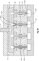
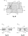
- the molding elements 140 may incorporate an ejector sleeve 220 (e.g., ejector sleeves 220a, 220b shown in FIG. 2 ), which may have one or more wear-resistant surfaces or surface segments.
- Such ejector sleeve 220 may be secured in one or more of the molding elements 140 ( e.g., in the molding element 140b) and may, in part, form one or more surfaces of the molding elements 140 that at least in part defines the molding volume 131 ( FIG. 1 ).
- the ejector pins 170 may pass through an opening 221 of the ejector sleeve 220 and eject the part 130.
- the ejector sleeve 220 may be secured to the ejector plates 122d and the opening 221 may fit around a core pin ( e.g., the core pin may be secured in the ejector housing 122c).
- such ejector sleeve 220 also may, at least in part, move toward the front platen 111 of the injection molding machine 110 to eject the part 130.
- the ejector pin 170 also may include a superhard material 170sm.
- a tip of the ejector pin 170 may incorporate superhard material 170sm, which may form a wear-resistant surface 170wr.
- the opening 221 may include a fitted portion 222 and a relieved portion 223.
- the fitted portion 222 may have a close fit with the ejector pins 170 or with the core pin, as applicable.
- the ejector pin 170 may be a cylindrical pin.
- the opening 221 may have a substantially cylindrical shape.
- ejector sleeve 220 may have a clearance between the internal diameter of the opening 221 and the outside diameter of the ejector pin 170 in the range of about 0.01 mm to about 0.15 mm.
- the relieve portion 223 of the opening 221 may have a clearance that is greater than 0.15 mm between the internal diameter of the opening 221 and the outside diameter of the ejector pin 170.
- the ejector sleeve 220 includes a wear-resistant surface 221wr, which is formed by a superhard material 220sm.
- the wear-resistant surface 221wr may extend along and cover the entire fitted portion 222 or a part of the fitted portion 222 of the opening 221.
- the wear-resistant surface 221wr also may cover the entire relieved portion 223 or a part of the relieved portion 223 of the opening 221.
- a portion of the ejector sleeve 220 may form part of one or more molding elements 140.
- a front face 224 of the ejector sleeve 220 may form part of the molding element 140b, which may contact at least a portion of the part 130 ( FIG. 2 ).
- the front face 224 may experience wear caused by the flow of molten molding material in contact with the front face 224.
- the ejector sleeve 220 also may include a wear-resistant surface 224wr.
- the wear-resistant surface 224wr may cover all or a portion of the front face 224 of the ejector sleeve 220 and/or ejector pin 170.
- thickness of the superhard material 220sm may vary, at least in part, based on the direction of the measurement. For instance, the thickness of the same superhard material 220sm may be measured from the wear-resistant surface 221wr as well as from wear-resistant surface 224wr. Moreover, thickness of the superhard material 220sm may be measured only from one of the wear-resistant surfaces 221wr, 224wr. More specifically, thickness of the superhard material 220sm (as measured from the wear-resistant surface 224wr) may be such as to cover part of the fitted portion 222 of the opening 221 ( FIG. 5B ). Alternatively, thickness of the superhard material 220sm may be such as to cover all of the fitted portion 222 and part of the relieved portion 223 of the opening 221 ( FIG. 5E ).
- the ejector sleeve 220 such as the ejector sleeve 220b ( FIG. 2 ) may move with respect to the core pin.
- the outside diameter 225 of the ejector sleeve 220 also may slide in contact with one or more molding elements 140 ( e.g., within an opening of the molding element 140b). Accordingly, the surface formed by the outside diameter 225 of the ejector sleeve 220 may experience wear associated with such sliding.
- a wear-resistant surface 225wr which may cover all or part of the surface formed by the outside diameter 225 of the ejector sleeve 220, may reduce such wear ( FIGS. 5B and 5E ). Furthermore, the wear-resistant surface 225wr may be formed by the same body superhard material 220sm that may form the wear-resistant surface 221wr and/or wear-resistant surface 224wr.
- the molding elements 140 may form or may have undercutting portions, such that the undercut must be relieved in order to eject the part 130 from the injection mold 120.
- the injection mold 120 may include an undercut relief system 230.
- the undercut relief system 230 may include a slide body 240 and a heel lock 250.
- the slide body 240 may secure one or more of the molding elements 140 ( e.g., a core 140d).
- the core 140d may form an undercutting portion of the part 130.
- the core 140d may form a hole or a ledge in the part 130.
- the slide body 240 may move the core 140d out of the formed hole, thereby allowing the part 130 to be ejected.
- an angular portion 251 of the heel lock 250 may contact a corresponding angular portion 241 of the slide body 240, which may aid in maintaining the slide body 240 in a desired position.
- an angle pin 260 may force the slide body 240 to move away from the part 130 (before the part 130 is ejected from the injection mold 120). More specifically, as the injection mold 120 opens, the moving portion 122 (which may include the second plate 122a and the support plate 122b) move away from the nonmoving portion 121 (which may include the first plate 121a and the top clamping plate 121b). The part 130 and the slide body 240 may remain on the moving portion 122; the slide body 240 may be restricted from movement away from the moving portion 122 by one or more gibs (not shown; see FIG. 6B-6G ), which may guide the slide body 240.
- the slide body 240 also may have a single degree of freedom of motion, to slide away from the part 130 ( e.g., along the second plate 122a).
- the slide body 240 moves away from the nonmoving portion 121, which secures the angle pin 260.
- the slide body 240 moves with respect to the angle pin 260, the slide body 240 is forced to slide away from the part 130.
- the angular portion 241 of the slide body 240 may have a wear-resistant surface that covers the entire or a part of the angular portion 241.
- a superhard material 240sm as described above, may form all or part of the surface of the angular portion 241. Accordingly, the surface of the angular portion 241 may have reduced wear (compared with another material, such as steel) from contact with the angular portion 251.
- the heel lock 250 also may incorporate a superhard material 250sm, which may form a wear-resistant surface on at least a part of the surface of the angular portion 251.
- the wear-resistant surface of the angular portion 251 may have a lower hardness than the wear-resistant surface of the angular portion 241.
- the wear-resistant surface of the angular portion 251 may have substantially the same or higher hardness than the wear-resistant surface of the angular portion 241.
- the angular portion 241 of the slide body 240 or the angular portion 251 of the heel lock 250 may at least partially incorporate a wearing surface.
- the term "wearing" surface refers to a surface that comprises a material that is softer than the superhard material of the wear-resistant surface that is in contact with the wearing surface. Suitable materials for the wearing surface include steel, brass, bronze, copper alloys, aluminum alloys, polytetrafluoroethylene (PTFA), combinations thereof, or other suitable material. Accordingly, the wearing surface may aid in reducing the amount of wear experienced by the wear-resistant surface.
- the wearing surface may comprise material that is softer than the superhard material that comprises the wear-resistant surface.
- a softer wearing surface may absorb more energy generated by friction at an interface between the wear-resistant surface and a contacting surface (e.g., the wearing surface) than by a harder contacting surface.
- the wearing surface also may have a reduced coefficient of friction (as compare to other suitable materials).
- the angular portion 241 of the slide body 240 may include a wear-resistant surface comprising superhard material (as described above), and the angular portion 251 may have a wearing surface, which may wear more quickly or easily than the wear-resistant surface of the angular portion 241, and which may increase the life of the wear-resistant surface of the angular portion 241.
- the wearing surface may be removable and replaceable.
- the wearing surface may comprise an insert that incorporates material that is softer than the wear-resistant surface that contacts the wearing surface. Hence, once the wearing surface has worn beyond an acceptable level, the insert comprising the wearing surface may be removed and replaced.
- the slide body 240 may be guided by one or more gibs 280 ( FIGS. 6B-6G ).
- the cross-sectional view in FIG. 6A shows a cross-section that does not pass through the gibs 280; by contrast, cross-sectional views shown in FIGS. 6B-6E show a cross-section that is orthogonal to the cross-section shown in FIG. 6A , and which passes through the gibs 280.
- the gibs 280 may have one or more surfaces that may prevent the slide body 240 from lifting off from a surface upon which the slide body 240 slides (e.g., a slide surface 290).
- the gibs 280 may have one or more retaining surfaces 281 (see FIG. 6F ), which may restrict lifting off of the slide body 240.
- the slide body 240 also may have one or more shoulder surfaces 243, which may interface (or interfere) with the retaining surfaces 281 of the gibs 280.
- the gibs 280 may have one or more surfaces that may control the direction of movement of the slide body 240, and which may limit deviation of the slide body 240 from such direction.
- the gibs 280 may have one or more side surfaces 282, 283, which may contact with one or more side surfaces 244, 245 of the slide body 240. Accordingly, the side surfaces 244, 245 of the slide body 240 may move in sliding contact with the side surfaces 282, 283 of the gibs 280, thereby guiding the slide body 240 along a desired path.
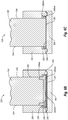
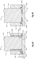
- one or more of the side surfaces 244, 245 may incorporate wear-resistant surfaces, which may cover the portion of side surfaces 244, 245 positioned within the gib 280s ( e.g., FIG. 6D ).
- FIG. 6D illustrates different examples of wear-resistant surfaces on the slide body 240 and on the gibs 280, which are shown differently on the left and the right sides of an assembly of the slide body 240 and gibs 280.
- the wear-resistant surfaces also may cover only a portion of one or more of the side surfaces 244, 245 ( e.g., FIGS. 6B, 6C , and 6E ).
- the side surfaces 244, 245 that incorporate, at least in part, the wear-resistant surfaces may experience reduced wear from the sliding in contact with the side surfaces 282 and/or 283 (as compared with a different material, such as steel).
- the wear-resistant surfaces incorporated into the side surfaces 244, 245 may be formed by a superhard material 240sm, which may be bonded to the slide body 240 through a substrate, directly, or may form part of an insert secured to the slide body 240.
- the one or more of the side surfaces 282, 283 also may incorporate one or more wear-resistant surfaces, which may cover the side surfaces 282, 283 entirely or partially.
- the wear-resistant surfaces formed on or incorporated into the side surfaces 282, 283 may have substantially the same hardness as the wear-resistant surface formed on or incorporated into the side surfaces 244, 245.
- the wear-resistant surfaces formed as or incorporated into the side surfaces 282, 283 may be softer than the wear-resistant surface formed as or incorporated into the side surfaces 244, 245.
- the wear-resistant surfaces formed on or incorporated into the side surfaces 282, 283 also may be harder than the wear-resistant surface formed on or incorporated into the side surfaces 244, 245.
- the one or more wear-resistant surfaces that form one or more of the side surfaces 244, 245 or the side surfaces 282, 283, may be continuous or interrupted, as illustrated in FIGS. 6B-6G .
- the gibs 280 may have multiple wear-resistant surfaces 281wr and/or side surfaces 282wr, 283wr that may at least partially form the retaining surfaces 281 and/or side surfaces 282, 283.
- the wear-resistant surfaces 281wr, 282wr, 283wr, or combinations thereof may comprise discrete surface segments, formed by multiple discrete layers or bodies of superhard material.
- the wear-resistant surfaces 281wr, 282wr, 283wr, or combinations thereof may be formed by a single layer or body of superhard material that has variable thickness to form raised portions, forming the wear-resistant surfaces 281wr, 282wr, and/or 283wr.
- one or more of the side surfaces 282, 283 of the gibs 280 may incorporate or may be formed as wearing surfaces, which have a substantially lower hardness than the wear-resistant surfaces.
- one or more of the side surfaces 244, 245 that may be formed as or incorporate wear-resistant surfaces may experience further reduced wear.
- the side surfaces 244, 245 of the slide body 240 may be formed as or may incorporate wearing surfaces, which may come into contact with wear-resistant surfaces formed as or incorporated into the side surfaces 282, 283.
- the slide body 240 may have a bottom sliding surface 246, which may slide in contact or across a top surface 291 of a slide plate 290.
- the slide plate 290 may be incorporated into or secured to a plate comprising the nonmoving portion 121 or moving portion 122 of the injection mold 120.
- the slide plate 290 also may be incorporated into or secured to one or more of the molding elements 140.
- the bottom sliding surface 246 of the slide body 240 may be formed as or may incorporate a wear-resistant surface 246wr. Similar to the wear-resistant surfaces described above, the wear-resistant surface 246wr may be formed from a single body or multiple bodies or layers of superhard material. Moreover, the bottom sliding surface 246 may be continuous or interrupted, and the wear-resistant surface 246wr may cover the entire bottom sliding surface 246 o only a part of the bottom sliding surface 246 of the slide body 240 ( FIGS. 6B-6E ).
- the top surface 291 of the slide plate 290 also may incorporate or may be formed as a wear-resistant surface (formed by a superhard material 290sm).
- a wear-resistant surface 291wr may be incorporated into or may at least partially form the top surface 291 of the slide plate 290.
- the wear-resistant surface 291wr may cover the entire or only a portion of the top surface 291.
- the wear-resistant surface 291wr may comprise discrete surface segments ( FIG. 6G ).
- the wear-resistant surface 291wr may comprise a unitary on continuous surface, which may be substantially level or may have raised and/or lowered portions therein.
- the injection mold 120 may include the angle pin 260, which may pull the slide body 240 away from the part 130 as the injection mold 120 opens ( FIG. 6A ). More specifically, the angle pin 260, which may remain stationary while the moving portion 122 moves away from the nonmoving portion 121, may guide the slide body 240 away from the part 130, as the moving portion 122 (including the slide body 240) moves away from the nonmoving portion 121. Alternatively, other mechanisms may be used to move the slide body 240 away from the part 130. For instance, the slide body 240 may be moved by a cylinder ( e.g., a hydraulic cylinder). Thus, as shown in FIG. 6A , the slide body 240 may have the opening 242, which may accommodate the angle pin 260 therein.
- a cylinder e.g., a hydraulic cylinder
- the surface of the opening 242 and/or of the angle pin 260 may include a wear-resistant surface.
- the wear-resistant surface may cover the entire or a part of the surface of the opening 242 in the slide body 240.
- the wear-resistant surface of the opening 242 may reduce the amount of wear experienced by the opening 242 from repeated entry, exit, and/or sliding movement of the angle pin 260 against the surface of the opening 242 of the slide body 240.
- the wear-resistant surface of the opening 242 may be formed by a superhard material 240sm, which may be bonded to a substrate (such substrate may in turn be bonded to the slide body 240), to the slide body 240 directly, or may comprise an insert that is secured to the slide body 240.
- the undercut relief system 230 also may include a slide retainer 270, which may secure the slide body 240 (e.g., when the injection mold 120 is in the open position).
- the slide retainer 270 may include a slide plate 271, and a retention ball 272 and a spring 274 ( i.e., a springloaded retention ball 272).
- the slide plate 271 moves past the spring loaded retention ball 272.
- the retention ball 272 may maintain the slide plate 271 (and consequently the slide body 240) in a fixed position.
- the bottom surface 273 of the slide plate 271 may include or may be formed by a wear-resistant surface formed by superhard material 270sm.
- the wear-resistant surface may cover (or form) the entire or only a part of the bottom surface 273 of the slide plate 271, as shown in FIG. 7A .
- superhard material 270sm which may form one or more wear-resistant surfaces, may be continuous across the entire bottom surface 273 of the slide plate 271 or may be interrupted. Moreover, as shown in FIG.
- superhard material 270sm may comprise an insert, which may be secured to the slide body 240 ( e.g., with mechanical fasteners such as screws or using bonding techniques, such as welding, brazing, etc.).
- the insert may comprise the superhard material 270sm bonded to a substrate ( FIG. 7B ).
- the entire insert may comprise superhard material- i.e., the superhard material 270sm may be an insert secured to the slide body 240.
- the injection mold 120 may include one or more interlock pairs 280 ( FIG. 2 ).
- the injection mold may include one or more rectangular two-plate interlock pairs 280a or interlock pairs having another suitable shape.
- the rectangular single side interlock pair 280a comprise a male interlock 281a and a female interlock 282a.
- the male interlock 281a may have a protrusion 283a, which may enter and substantially align with a recess 284a within the female interlock 282a.
- the protrusion 283a and/or the recess 284a may respectively incorporate superhard material 283sm, 284sm.
- the protrusion and 283a and the recess 284a also may include wear resistant surfaces 283wr, 284wr, respectively.
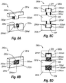
- superhard material 283sm and 284sm may form the wear-resistant surfaces 283wr, 284wr that may define the entire surface of the protrusion and the recess (as shown in FIGS. 8A and 8B ) or portions thereof. Additionally or alternatively, the superhard material 283sm may form wear-resistant surfaces 283wr only on the sides of the protrusion 283a, as shown in FIG. 8A . Similarly, the superhard material 284sm may form wear-resistant surface 284wr only on the sides of the recess 284.
- the superhard material 283sm, 284sm may form the entire protrusion 283 and recess 284, as shown in FIG. 8B .
- the superhard material 283sm, 284sm may form other wear-resistant surfaces, in addition to the side surfaces of the protrusion 283 and the recess 284.
- the part material 284sm may form a bottom wear-resistant surface 284wr of the recess 284.
- superhard material 283sm, 284sm may comprise one or more inserts, which may be secured within the male interlock 281a and/or the female interlock 282a.
- the injection mold may include a three-plate interlock pair 280b, as shown in FIGS. 8C and 8D , which may align three plates of the injection mold.
- the three-plate interlock pair 280b may include a male interlock 281b, which may enter into two opposing female interlocks 282b.
- the male interlock 281b may include two opposing protrusions 283b, which may enter into recesses 284b of the female interlocks 282b. Similar, as described above in connection with the rectangular two-plate interlock pairs 280a ( FIGS.
- the three-plate interlock pair 280b may incorporate superhard material 283sm, 284sm, which may form wear-resistant surfaces 283wr, 284wr of the protrusions 283 and recesses 284, respectively.
- the superhard material 283sm, 284sm may form wear-resistant surfaces 283wr, 284wr only on the respective sides of the protrusions 283 and recesses 284 that contact one another ( FIG. 8C ). Additionally or alternatively, the superhard material 283sm, 284sm also may form wear-resistant surfaces 283wr, 284wr on other sides and/or portions of the male and female interlocks 281, 282. For instance, as shown in FIG. 8D , the superhard material 283sm, 284sm may form the entire protrusion 283 and/or recess 284, respectively.
- the injection mold also may include tapered interlocks.
- the injection mold may incorporate one or more tapered interlock pairs 280c.
- the tapered interlock pair 280c may comprise a male interlock 281c and a corresponding female interlock 282c.
- the male interlock 281c may include a tapered protrusion 283c that may enter a corresponding tapered recess 284c in the female interlock.
- the tapered interlock pair 280c may include superhard material 283sm, 284sm, which may form wear-resistant surfaces 283wr, 284wr.
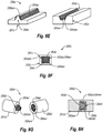
- the superhard material 283sm, 284sm may form only the surfaces 283wr, 284wr of the respective protrusion 283c and recess 284c that may contact one another when the tapered interlock pair 280c closes, as described above ( see also FIG. 8E ).
- the superhard material 283sm, 284sm also may form the protrusion 283c and/or the recess 284c ( FIG. 8F ).
- the tapered interlock pair may be a cylindrical tapered interlock pair 280d, as shown in FIGS. 8G and 8H .
- the cylindrical tapered interlock pair 280d may comprise a male and female interlocks 281d, 282d, which may have a corresponding protrusion 283d and recess 284d.
- the protrusion 283 and recess 284 may include superhard material 283sm, 284sm, respectively, which may form wear-resistant surfaces 283wr, 284wr.
- the wear-resistant surfaces 283wr, 284wr may form only the one or more surfaces of the respective protrusion and recess 283, 284 that may contact one another when the cylindrical tapered interlock pair 280d closes ( FIG. 8G ). Additionally or alternatively, the superhard material 283sm, 284sm may form the respective protrusion and/or recess 283, 284 ( FIG . 8H ).
Landscapes
- Engineering & Computer Science (AREA)
- Manufacturing & Machinery (AREA)
- Mechanical Engineering (AREA)
- Moulds For Moulding Plastics Or The Like (AREA)
Claims (13)
- Spritzgussformkomponente zur Verwendung in einer Spritzgussform (120),
wobei die Spritzgussformkomponente eine Auswerferhülse (220) ist, die eine Öffnung (221) als Durchtritt für einen oder mehrere Auswerferstifte (170) aufweist, die Auswerferhülse (220) ist dadurch gekennzeichnet, dass diese umfasst:eine erste verschleißbeständige Oberfläche (221wr), die zumindest teilweise einen Innendurchmesser (221) der Auswerferhülse (220) definiert, eine zweite verschleißbeständige Oberfläche (225wr), die eine erste Oberfläche eines Außendurchmessers (225) der Auswerferhülse (220) definiert, und einen metallischen Werkstoff, der eine zweite Oberfläche des Außendurchmessers (225) definiert und sich von der zweiten verschleißbeständigen Oberfläche (225wr) erstreckt;ein Hartmetallsubstrat; undein superharter Werkstoff (220sm), der an das Hartmetallsubstrat gebunden ist und die erste verschleißbständige Oberfläche (221wr) und die zweite verschleißbeständige Oberfläche (225) bildet; wobei der superharte Werkstoff polykristallinen Diamant mit einer Vielzahl von gebundenen Diamantkörnern umfasst, die Zwischenbereiche definieren, von denen zumindest ein Teil darin einen Katalysator aufweist. - Spritzgussformkomponente nach Anspruch 1, wobei der superharte Werkstoff ferner wenigstens einen Werkstoff umfasst, der aus der Gruppe bestehend aus, polykristallinem kubischem Bornitrid, Siliciumcarbid und Wolframcarbid, ausgewählt ist.
- Spritzgussformkomponente nach Anspruch 1, wobei der superharte Werkstoff ein oder mehr Segmente umfasst, die mindestens einen Abschnitt von wenigstens einer der ersten verschleißbeständigen Oberfläche oder der zweiten verschleißbeständigen Oberfläche definieren.
- Spritzgussformkomponente nach Anspruch 1, wobei zumindest die eine erste verschleißbeständige Oberfläche oder zweite verschleißbeständige Oberfläche eine Härte aufweist, die größer ist als die einer Verschleißfläche.
- Spritzgussformkomponente nach Anspruch 1, wobei das Substrat Wolframkarbidhartmetall enthält.
- Spritzgussformanordnung, umfassend:eine erste Werkzeugplatte (121a);eine zweite Werkzeugplatte (122a);ein oder mehrere Formelemente (140), die auf einer oder mehrere der ersten oder zweiten Werkzeugplatten angeordnet sind; wobei die Spritzgussformkomponente (220a. 220b) nach einem der Ansprüche 1 bis 5, wenigstens auf der ersten Werkzeugplatte, der zweiten Werkzeugplatte oder dem Formelement angeordnet ist.
- Spritzgussformanordnung nach Anspruch 6, wobei der superharte Werkstoff und das Substrat einen Einsatz definieren; und der Einsatz mit der Spritzgussformkomponente verbunden ist.
- Spritzgussformanordnung nach Anspruch 7, wobei der Einsatz in Presspassung mit der Spritzgussformkomponente steht.
- Spritzgussformanordnung nach Anspruch 7, wobei der Einsatz entfernbare Befestigungselemente umfasst, die den Einsatz an der Spritzgussformkomponente befestigen.
- Spritzgussformanordnung nach Anspruch 6, wobei das Substrat in die Spritzgussformkomponente integriert ist
- Spritzgusssystem, umfassend:eine Spritzgussmaschine;eine Spritzgussform (120), die betriebsmäßig mit der Spritzgussmaschine gekoppelt ist, wobei die Spritzgussform umfasst:einen stationären Abschnitt (121);einen beweglichen Abschnitt (122);ein Formelement (140), das wenigstens an dem stationären Abschnitte oder dem beweglichen Abschnitt angeordnet ist; wobeidie Spritzgussformkomponente (220a, 220b) nach einem der Ansprüche 1 bis 5, an wenigstens dem stationären Abschnitt oder dem beweglichen Abschnitt angeordnet ist.
- Spritzgusssystem nach Anspruch 11, wobei das Substrat in die Spritzgussformkomponente integriert ist.
- Spritzgusssystem nach Anspruch 11, wobei die Spritzgussmaschine dazu konfiguriert ist, um Formmaterial über eine Leitung, die zumindest teilweise durch polykristallinen Diamant definiert ist, in die Spritzgussform einzuspritzen.
Applications Claiming Priority (2)
| Application Number | Priority Date | Filing Date | Title |
|---|---|---|---|
| US13/463,471 US8702412B2 (en) | 2011-01-12 | 2012-05-03 | Superhard components for injection molds |
| PCT/US2013/039101 WO2013166175A2 (en) | 2012-05-03 | 2013-05-01 | Superhard components for injection molds |
Publications (2)
| Publication Number | Publication Date |
|---|---|
| EP2844452A2 EP2844452A2 (de) | 2015-03-11 |
| EP2844452B1 true EP2844452B1 (de) | 2020-04-08 |
Family
ID=48464093
Family Applications (1)
| Application Number | Title | Priority Date | Filing Date |
|---|---|---|---|
| EP13723609.7A Active EP2844452B1 (de) | 2012-05-03 | 2013-05-01 | Superharte komponenten für spritzgussformen |
Country Status (2)
| Country | Link |
|---|---|
| EP (1) | EP2844452B1 (de) |
| WO (1) | WO2013166175A2 (de) |
Family Cites Families (6)
| Publication number | Priority date | Publication date | Assignee | Title |
|---|---|---|---|---|
| JPH06106543A (ja) * | 1992-09-29 | 1994-04-19 | Sekisui Chem Co Ltd | 塩化ビニル系樹脂成形用金型 |
| JPH08132443A (ja) * | 1994-11-09 | 1996-05-28 | Sony Corp | 金型位置決め構造 |
| JP2001047158A (ja) * | 1999-07-30 | 2001-02-20 | Fuji Dies Kk | 耐食性超硬合金製金型用柱状案内具 |
| US7134868B2 (en) | 2003-11-26 | 2006-11-14 | Mold-Masters Limited | Injection molding nozzle with wear-resistant tip having diamond-type coating |
| US7939181B2 (en) * | 2006-10-11 | 2011-05-10 | Oerlikon Trading Ag, Trubbach | Layer system with at least one mixed crystal layer of a multi-oxide |
| US8512023B2 (en) * | 2011-01-12 | 2013-08-20 | Us Synthetic Corporation | Injection mold assembly including an injection mold cavity at least partially defined by a polycrystalline diamond material |
-
2013
- 2013-05-01 EP EP13723609.7A patent/EP2844452B1/de active Active
- 2013-05-01 WO PCT/US2013/039101 patent/WO2013166175A2/en not_active Ceased
Non-Patent Citations (1)
| Title |
|---|
| STEVEN J. BALES: "Know Your Mold Coatings", 1 December 2004 (2004-12-01), ptonline.com, XP055484180, Retrieved from the Internet <URL:https://www.ptonline.com/articles/know-your-mold-coatings> [retrieved on 20180614] * |
Also Published As
| Publication number | Publication date |
|---|---|
| WO2013166175A3 (en) | 2013-12-27 |
| EP2844452A2 (de) | 2015-03-11 |
| WO2013166175A2 (en) | 2013-11-07 |
Similar Documents
| Publication | Publication Date | Title |
|---|---|---|
| US9868229B2 (en) | Methods of injection molding an article | |
| US9193103B2 (en) | Methods of injection molding | |
| JP4982811B2 (ja) | 光学素子成形装置 | |
| EP3463796B1 (de) | Formsperrenstrukturen | |
| TW201400268A (zh) | 具有一簡化冷卻系統之射出模具 | |
| AU710744B2 (en) | Ejecting method of a molding in an injection molding apparatus and a molding produced by using the ejecting method | |
| EP1375107A1 (de) | Düsenspitze für Spritzgiesswerkzeuge mit Heisskanälen | |
| CN101444946A (zh) | 导光板的成形模具 | |
| USRE38617E1 (en) | Method of injection molding plastic lens | |
| JP5708640B2 (ja) | 成形金型及び樹脂成形品の製造方法 | |
| JP2009073185A (ja) | 薄板成形品の成形金型 | |
| JP5105613B2 (ja) | 射出圧縮成形金型 | |
| CN100469553C (zh) | 金属模装置、模制品、其成形方法、成形机和衬套 | |
| WO2013166175A2 (en) | Superhard components for injection molds | |
| KR100934406B1 (ko) | 핫 러너 시스템 | |
| CN100415476C (zh) | 金属模装置及其制造方法、成形方法及成形机 | |
| EP3837101B1 (de) | Winkelstiftbuchse und spritzgiessschieber damit | |
| JP5234640B2 (ja) | 極薄導光板の成形金型および成形方法 | |
| US11858178B2 (en) | Injection mold for timepiece component | |
| JP4869990B2 (ja) | 射出成形用金型およびこれを用いた射出成形方法 | |
| CN212446139U (zh) | 嵌件局部受热的嵌件成型模具 | |
| JP7706937B2 (ja) | 射出成形機、射出成形システム、樹脂成形品の製造方法および射出成型方法 | |
| WO2013024891A1 (ja) | ガラスモールド用の成形金型、光学素子の製造方法、及び光学素子 | |
| JP2009285913A (ja) | 射出圧縮成形金型、射出圧縮成形金型の調整方法、および射出圧縮成形システム | |
| EP4100225B1 (de) | Spritzgiessmaschine mit einem führungsschienensystem für einen formwerkzeugaufbau |
Legal Events
| Date | Code | Title | Description |
|---|---|---|---|
| PUAI | Public reference made under article 153(3) epc to a published international application that has entered the european phase |
Free format text: ORIGINAL CODE: 0009012 |
|
| 17P | Request for examination filed |
Effective date: 20141031 |
|
| AK | Designated contracting states |
Kind code of ref document: A2 Designated state(s): AL AT BE BG CH CY CZ DE DK EE ES FI FR GB GR HR HU IE IS IT LI LT LU LV MC MK MT NL NO PL PT RO RS SE SI SK SM TR |
|
| AX | Request for extension of the european patent |
Extension state: BA ME |
|
| DAX | Request for extension of the european patent (deleted) | ||
| 17Q | First examination report despatched |
Effective date: 20160901 |
|
| STAA | Information on the status of an ep patent application or granted ep patent |
Free format text: STATUS: EXAMINATION IS IN PROGRESS |
|
| GRAP | Despatch of communication of intention to grant a patent |
Free format text: ORIGINAL CODE: EPIDOSNIGR1 |
|
| STAA | Information on the status of an ep patent application or granted ep patent |
Free format text: STATUS: GRANT OF PATENT IS INTENDED |
|
| INTG | Intention to grant announced |
Effective date: 20191031 |
|
| GRAS | Grant fee paid |
Free format text: ORIGINAL CODE: EPIDOSNIGR3 |
|
| GRAA | (expected) grant |
Free format text: ORIGINAL CODE: 0009210 |
|
| STAA | Information on the status of an ep patent application or granted ep patent |
Free format text: STATUS: THE PATENT HAS BEEN GRANTED |
|
| AK | Designated contracting states |
Kind code of ref document: B1 Designated state(s): AL AT BE BG CH CY CZ DE DK EE ES FI FR GB GR HR HU IE IS IT LI LT LU LV MC MK MT NL NO PL PT RO RS SE SI SK SM TR |
|
| REG | Reference to a national code |
Ref country code: AT Ref legal event code: REF Ref document number: 1253788 Country of ref document: AT Kind code of ref document: T Effective date: 20200415 Ref country code: CH Ref legal event code: EP |
|
| REG | Reference to a national code |
Ref country code: IE Ref legal event code: FG4D |
|
| REG | Reference to a national code |
Ref country code: DE Ref legal event code: R096 Ref document number: 602013067666 Country of ref document: DE |
|
| REG | Reference to a national code |
Ref country code: NL Ref legal event code: MP Effective date: 20200408 |
|
| REG | Reference to a national code |
Ref country code: LT Ref legal event code: MG4D |
|
| PG25 | Lapsed in a contracting state [announced via postgrant information from national office to epo] |
Ref country code: NL Free format text: LAPSE BECAUSE OF FAILURE TO SUBMIT A TRANSLATION OF THE DESCRIPTION OR TO PAY THE FEE WITHIN THE PRESCRIBED TIME-LIMIT Effective date: 20200408 Ref country code: SE Free format text: LAPSE BECAUSE OF FAILURE TO SUBMIT A TRANSLATION OF THE DESCRIPTION OR TO PAY THE FEE WITHIN THE PRESCRIBED TIME-LIMIT Effective date: 20200408 Ref country code: IS Free format text: LAPSE BECAUSE OF FAILURE TO SUBMIT A TRANSLATION OF THE DESCRIPTION OR TO PAY THE FEE WITHIN THE PRESCRIBED TIME-LIMIT Effective date: 20200808 Ref country code: LT Free format text: LAPSE BECAUSE OF FAILURE TO SUBMIT A TRANSLATION OF THE DESCRIPTION OR TO PAY THE FEE WITHIN THE PRESCRIBED TIME-LIMIT Effective date: 20200408 Ref country code: FI Free format text: LAPSE BECAUSE OF FAILURE TO SUBMIT A TRANSLATION OF THE DESCRIPTION OR TO PAY THE FEE WITHIN THE PRESCRIBED TIME-LIMIT Effective date: 20200408 Ref country code: PT Free format text: LAPSE BECAUSE OF FAILURE TO SUBMIT A TRANSLATION OF THE DESCRIPTION OR TO PAY THE FEE WITHIN THE PRESCRIBED TIME-LIMIT Effective date: 20200817 Ref country code: NO Free format text: LAPSE BECAUSE OF FAILURE TO SUBMIT A TRANSLATION OF THE DESCRIPTION OR TO PAY THE FEE WITHIN THE PRESCRIBED TIME-LIMIT Effective date: 20200708 Ref country code: GR Free format text: LAPSE BECAUSE OF FAILURE TO SUBMIT A TRANSLATION OF THE DESCRIPTION OR TO PAY THE FEE WITHIN THE PRESCRIBED TIME-LIMIT Effective date: 20200709 |
|
| REG | Reference to a national code |
Ref country code: AT Ref legal event code: MK05 Ref document number: 1253788 Country of ref document: AT Kind code of ref document: T Effective date: 20200408 |
|
| PG25 | Lapsed in a contracting state [announced via postgrant information from national office to epo] |
Ref country code: HR Free format text: LAPSE BECAUSE OF FAILURE TO SUBMIT A TRANSLATION OF THE DESCRIPTION OR TO PAY THE FEE WITHIN THE PRESCRIBED TIME-LIMIT Effective date: 20200408 Ref country code: LV Free format text: LAPSE BECAUSE OF FAILURE TO SUBMIT A TRANSLATION OF THE DESCRIPTION OR TO PAY THE FEE WITHIN THE PRESCRIBED TIME-LIMIT Effective date: 20200408 Ref country code: BG Free format text: LAPSE BECAUSE OF FAILURE TO SUBMIT A TRANSLATION OF THE DESCRIPTION OR TO PAY THE FEE WITHIN THE PRESCRIBED TIME-LIMIT Effective date: 20200708 Ref country code: RS Free format text: LAPSE BECAUSE OF FAILURE TO SUBMIT A TRANSLATION OF THE DESCRIPTION OR TO PAY THE FEE WITHIN THE PRESCRIBED TIME-LIMIT Effective date: 20200408 |
|
| PG25 | Lapsed in a contracting state [announced via postgrant information from national office to epo] |
Ref country code: AL Free format text: LAPSE BECAUSE OF FAILURE TO SUBMIT A TRANSLATION OF THE DESCRIPTION OR TO PAY THE FEE WITHIN THE PRESCRIBED TIME-LIMIT Effective date: 20200408 |
|
| REG | Reference to a national code |
Ref country code: DE Ref legal event code: R097 Ref document number: 602013067666 Country of ref document: DE |
|
| PG25 | Lapsed in a contracting state [announced via postgrant information from national office to epo] |
Ref country code: RO Free format text: LAPSE BECAUSE OF FAILURE TO SUBMIT A TRANSLATION OF THE DESCRIPTION OR TO PAY THE FEE WITHIN THE PRESCRIBED TIME-LIMIT Effective date: 20200408 Ref country code: AT Free format text: LAPSE BECAUSE OF FAILURE TO SUBMIT A TRANSLATION OF THE DESCRIPTION OR TO PAY THE FEE WITHIN THE PRESCRIBED TIME-LIMIT Effective date: 20200408 Ref country code: CZ Free format text: LAPSE BECAUSE OF FAILURE TO SUBMIT A TRANSLATION OF THE DESCRIPTION OR TO PAY THE FEE WITHIN THE PRESCRIBED TIME-LIMIT Effective date: 20200408 Ref country code: IT Free format text: LAPSE BECAUSE OF FAILURE TO SUBMIT A TRANSLATION OF THE DESCRIPTION OR TO PAY THE FEE WITHIN THE PRESCRIBED TIME-LIMIT Effective date: 20200408 Ref country code: SM Free format text: LAPSE BECAUSE OF FAILURE TO SUBMIT A TRANSLATION OF THE DESCRIPTION OR TO PAY THE FEE WITHIN THE PRESCRIBED TIME-LIMIT Effective date: 20200408 Ref country code: EE Free format text: LAPSE BECAUSE OF FAILURE TO SUBMIT A TRANSLATION OF THE DESCRIPTION OR TO PAY THE FEE WITHIN THE PRESCRIBED TIME-LIMIT Effective date: 20200408 Ref country code: LI Free format text: LAPSE BECAUSE OF NON-PAYMENT OF DUE FEES Effective date: 20200531 Ref country code: DK Free format text: LAPSE BECAUSE OF FAILURE TO SUBMIT A TRANSLATION OF THE DESCRIPTION OR TO PAY THE FEE WITHIN THE PRESCRIBED TIME-LIMIT Effective date: 20200408 Ref country code: CH Free format text: LAPSE BECAUSE OF NON-PAYMENT OF DUE FEES Effective date: 20200531 Ref country code: ES Free format text: LAPSE BECAUSE OF FAILURE TO SUBMIT A TRANSLATION OF THE DESCRIPTION OR TO PAY THE FEE WITHIN THE PRESCRIBED TIME-LIMIT Effective date: 20200408 Ref country code: MC Free format text: LAPSE BECAUSE OF FAILURE TO SUBMIT A TRANSLATION OF THE DESCRIPTION OR TO PAY THE FEE WITHIN THE PRESCRIBED TIME-LIMIT Effective date: 20200408 |
|
| PLBE | No opposition filed within time limit |
Free format text: ORIGINAL CODE: 0009261 |
|
| STAA | Information on the status of an ep patent application or granted ep patent |
Free format text: STATUS: NO OPPOSITION FILED WITHIN TIME LIMIT |
|
| PG25 | Lapsed in a contracting state [announced via postgrant information from national office to epo] |
Ref country code: SK Free format text: LAPSE BECAUSE OF FAILURE TO SUBMIT A TRANSLATION OF THE DESCRIPTION OR TO PAY THE FEE WITHIN THE PRESCRIBED TIME-LIMIT Effective date: 20200408 Ref country code: PL Free format text: LAPSE BECAUSE OF FAILURE TO SUBMIT A TRANSLATION OF THE DESCRIPTION OR TO PAY THE FEE WITHIN THE PRESCRIBED TIME-LIMIT Effective date: 20200408 |
|
| 26N | No opposition filed |
Effective date: 20210112 |
|
| REG | Reference to a national code |
Ref country code: BE Ref legal event code: MM Effective date: 20200531 |
|
| PG25 | Lapsed in a contracting state [announced via postgrant information from national office to epo] |
Ref country code: LU Free format text: LAPSE BECAUSE OF NON-PAYMENT OF DUE FEES Effective date: 20200501 |
|
| PG25 | Lapsed in a contracting state [announced via postgrant information from national office to epo] |
Ref country code: FR Free format text: LAPSE BECAUSE OF NON-PAYMENT OF DUE FEES Effective date: 20200608 |
|
| PG25 | Lapsed in a contracting state [announced via postgrant information from national office to epo] |
Ref country code: SI Free format text: LAPSE BECAUSE OF FAILURE TO SUBMIT A TRANSLATION OF THE DESCRIPTION OR TO PAY THE FEE WITHIN THE PRESCRIBED TIME-LIMIT Effective date: 20200408 Ref country code: BE Free format text: LAPSE BECAUSE OF NON-PAYMENT OF DUE FEES Effective date: 20200531 |
|
| PGFP | Annual fee paid to national office [announced via postgrant information from national office to epo] |
Ref country code: IE Payment date: 20220309 Year of fee payment: 10 Ref country code: GB Payment date: 20220310 Year of fee payment: 10 |
|
| PG25 | Lapsed in a contracting state [announced via postgrant information from national office to epo] |
Ref country code: TR Free format text: LAPSE BECAUSE OF FAILURE TO SUBMIT A TRANSLATION OF THE DESCRIPTION OR TO PAY THE FEE WITHIN THE PRESCRIBED TIME-LIMIT Effective date: 20200408 Ref country code: MT Free format text: LAPSE BECAUSE OF FAILURE TO SUBMIT A TRANSLATION OF THE DESCRIPTION OR TO PAY THE FEE WITHIN THE PRESCRIBED TIME-LIMIT Effective date: 20200408 Ref country code: CY Free format text: LAPSE BECAUSE OF FAILURE TO SUBMIT A TRANSLATION OF THE DESCRIPTION OR TO PAY THE FEE WITHIN THE PRESCRIBED TIME-LIMIT Effective date: 20200408 |
|
| PG25 | Lapsed in a contracting state [announced via postgrant information from national office to epo] |
Ref country code: MK Free format text: LAPSE BECAUSE OF FAILURE TO SUBMIT A TRANSLATION OF THE DESCRIPTION OR TO PAY THE FEE WITHIN THE PRESCRIBED TIME-LIMIT Effective date: 20200408 |
|
| PGFP | Annual fee paid to national office [announced via postgrant information from national office to epo] |
Ref country code: DE Payment date: 20220309 Year of fee payment: 10 |
|
| P01 | Opt-out of the competence of the unified patent court (upc) registered |
Effective date: 20230525 |
|
| REG | Reference to a national code |
Ref country code: DE Ref legal event code: R119 Ref document number: 602013067666 Country of ref document: DE |
|
| GBPC | Gb: european patent ceased through non-payment of renewal fee |
Effective date: 20230501 |
|
| REG | Reference to a national code |
Ref country code: IE Ref legal event code: MM4A |
|
| PG25 | Lapsed in a contracting state [announced via postgrant information from national office to epo] |
Ref country code: IE Free format text: LAPSE BECAUSE OF NON-PAYMENT OF DUE FEES Effective date: 20230501 |
|
| PG25 | Lapsed in a contracting state [announced via postgrant information from national office to epo] |
Ref country code: IE Free format text: LAPSE BECAUSE OF NON-PAYMENT OF DUE FEES Effective date: 20230501 Ref country code: DE Free format text: LAPSE BECAUSE OF NON-PAYMENT OF DUE FEES Effective date: 20231201 Ref country code: GB Free format text: LAPSE BECAUSE OF NON-PAYMENT OF DUE FEES Effective date: 20230501 |