EP2843479A1 - Electrophotographic image forming apparatus - Google Patents
Electrophotographic image forming apparatus Download PDFInfo
- Publication number
- EP2843479A1 EP2843479A1 EP14172621.6A EP14172621A EP2843479A1 EP 2843479 A1 EP2843479 A1 EP 2843479A1 EP 14172621 A EP14172621 A EP 14172621A EP 2843479 A1 EP2843479 A1 EP 2843479A1
- Authority
- EP
- European Patent Office
- Prior art keywords
- toner
- cartridge
- location
- toner cartridge
- developer
- Prior art date
- Legal status (The legal status is an assumption and is not a legal conclusion. Google has not performed a legal analysis and makes no representation as to the accuracy of the status listed.)
- Granted
Links
- 230000001105 regulatory effect Effects 0.000 claims abstract description 84
- 238000007789 sealing Methods 0.000 claims description 24
- 238000000034 method Methods 0.000 description 21
- 238000003780 insertion Methods 0.000 description 18
- 230000037431 insertion Effects 0.000 description 18
- 239000003795 chemical substances by application Substances 0.000 description 13
- 238000004140 cleaning Methods 0.000 description 6
- 238000010438 heat treatment Methods 0.000 description 6
- 230000001678 irradiating effect Effects 0.000 description 3
- 238000010586 diagram Methods 0.000 description 2
- 238000007599 discharging Methods 0.000 description 2
- 230000000694 effects Effects 0.000 description 2
- 239000000463 material Substances 0.000 description 2
- 238000005192 partition Methods 0.000 description 2
- 230000015572 biosynthetic process Effects 0.000 description 1
- 230000007423 decrease Effects 0.000 description 1
- 230000001419 dependent effect Effects 0.000 description 1
- 230000014509 gene expression Effects 0.000 description 1
- 229910052736 halogen Inorganic materials 0.000 description 1
- 150000002367 halogens Chemical class 0.000 description 1
- 238000007689 inspection Methods 0.000 description 1
- 239000002184 metal Substances 0.000 description 1
- 230000002093 peripheral effect Effects 0.000 description 1
- 229920002379 silicone rubber Polymers 0.000 description 1
Images


Classifications
-
- G—PHYSICS
- G03—PHOTOGRAPHY; CINEMATOGRAPHY; ANALOGOUS TECHNIQUES USING WAVES OTHER THAN OPTICAL WAVES; ELECTROGRAPHY; HOLOGRAPHY
- G03G—ELECTROGRAPHY; ELECTROPHOTOGRAPHY; MAGNETOGRAPHY
- G03G15/00—Apparatus for electrographic processes using a charge pattern
- G03G15/06—Apparatus for electrographic processes using a charge pattern for developing
- G03G15/08—Apparatus for electrographic processes using a charge pattern for developing using a solid developer, e.g. powder developer
- G03G15/0822—Arrangements for preparing, mixing, supplying or dispensing developer
- G03G15/0877—Arrangements for metering and dispensing developer from a developer cartridge into the development unit
-
- G—PHYSICS
- G03—PHOTOGRAPHY; CINEMATOGRAPHY; ANALOGOUS TECHNIQUES USING WAVES OTHER THAN OPTICAL WAVES; ELECTROGRAPHY; HOLOGRAPHY
- G03G—ELECTROGRAPHY; ELECTROPHOTOGRAPHY; MAGNETOGRAPHY
- G03G21/00—Arrangements not provided for by groups G03G13/00 - G03G19/00, e.g. cleaning, elimination of residual charge
- G03G21/16—Mechanical means for facilitating the maintenance of the apparatus, e.g. modular arrangements
- G03G21/1642—Mechanical means for facilitating the maintenance of the apparatus, e.g. modular arrangements for connecting the different parts of the apparatus
- G03G21/1647—Mechanical connection means
-
- G—PHYSICS
- G03—PHOTOGRAPHY; CINEMATOGRAPHY; ANALOGOUS TECHNIQUES USING WAVES OTHER THAN OPTICAL WAVES; ELECTROGRAPHY; HOLOGRAPHY
- G03G—ELECTROGRAPHY; ELECTROPHOTOGRAPHY; MAGNETOGRAPHY
- G03G21/00—Arrangements not provided for by groups G03G13/00 - G03G19/00, e.g. cleaning, elimination of residual charge
- G03G21/16—Mechanical means for facilitating the maintenance of the apparatus, e.g. modular arrangements
- G03G21/1661—Mechanical means for facilitating the maintenance of the apparatus, e.g. modular arrangements means for handling parts of the apparatus in the apparatus
- G03G21/1676—Mechanical means for facilitating the maintenance of the apparatus, e.g. modular arrangements means for handling parts of the apparatus in the apparatus for the developer unit
-
- G—PHYSICS
- G03—PHOTOGRAPHY; CINEMATOGRAPHY; ANALOGOUS TECHNIQUES USING WAVES OTHER THAN OPTICAL WAVES; ELECTROGRAPHY; HOLOGRAPHY
- G03G—ELECTROGRAPHY; ELECTROPHOTOGRAPHY; MAGNETOGRAPHY
- G03G21/00—Arrangements not provided for by groups G03G13/00 - G03G19/00, e.g. cleaning, elimination of residual charge
- G03G21/16—Mechanical means for facilitating the maintenance of the apparatus, e.g. modular arrangements
- G03G21/18—Mechanical means for facilitating the maintenance of the apparatus, e.g. modular arrangements using a processing cartridge, whereby the process cartridge comprises at least two image processing means in a single unit
- G03G21/1839—Means for handling the process cartridge in the apparatus body
- G03G21/1842—Means for handling the process cartridge in the apparatus body for guiding and mounting the process cartridge, positioning, alignment, locks
-
- G—PHYSICS
- G03—PHOTOGRAPHY; CINEMATOGRAPHY; ANALOGOUS TECHNIQUES USING WAVES OTHER THAN OPTICAL WAVES; ELECTROGRAPHY; HOLOGRAPHY
- G03G—ELECTROGRAPHY; ELECTROPHOTOGRAPHY; MAGNETOGRAPHY
- G03G2221/00—Processes not provided for by group G03G2215/00, e.g. cleaning or residual charge elimination
- G03G2221/16—Mechanical means for facilitating the maintenance of the apparatus, e.g. modular arrangements and complete machine concepts
- G03G2221/1651—Mechanical means for facilitating the maintenance of the apparatus, e.g. modular arrangements and complete machine concepts for connecting the different parts
- G03G2221/1654—Locks and means for positioning or alignment
Definitions
- One or more embodiments of the present disclosure relate to an electrophotographic image forming apparatus, and more particularly, to an electrophotographic image forming apparatus capable of guaranteeing a stable connection of a developer (development) cartridge and a toner cartridge in a mounting process and minimizing effect due to vibration when mounted.
- Image forming apparatuses are apparatuses forming an image on a recording medium according to signals that are input, and the image forming apparatuses include printers, photocopiers, fax machines, and multi-function peripherals realized by integrating functions of the printers, the photocopiers, and the fax machines.
- Image forming apparatuses are configured by including a body loading or supplying paper and supporting or driving various components in the image forming apparatuses, and a developing unit mounted in the body and forming an image on the paper.
- the developing unit may be classified as a one-piece way or a two-piece way according to a print speed, a developing method, and a system layout.
- the one-piece way is a way in which a portion forming an image and a portion supplying toner are not separated but prepared in one developing unit.
- the two-piece way is a way in which the portion forming the image and the portion supplying the toner are separated as a developer cartridge and a toner cartridge respectively and mounted in a body of the image forming apparatuses additionally.
- the developing unit has a structure in which toner contained in the toner cartridge is supplied to the developer cartridge.
- toner may not smoothly be supplied or may leak outside the developer cartridge or the toner cartridge, when the toner is transported from the toner cartridge to the developer cartridge.
- an electrophotographic image forming apparatus which has an improved structure in which a location of a toner cartridge is regulated within a consistent margin of error while the toner cartridge is mounted in a body to be connected to a developer cartridge, and, the toner cartridge and the developer cartridge may be spaced apart from each other after the toner cartridge is completely mounted in the body.
- an electrophotographic image forming apparatus which includes: a body frame; a developer cartridge mounted in the body frame to be detachable; a toner cartridge mounted in the body frame to be detachable, and capable of moving to a first location where the toner cartridge starts to connect to the developer cartridge to supply toner and to a second location where the connection of the toner cartridge and the developer cartridge to supply the toner is completed; at least one first location regulating member provided in the developer cartridge, and regulating a relative location of the toner cartridge with respect to the developer cartridge when the toner cartridge is located in the first location; and at least one second location regulating member provided in the body frame, and regulating a relative location of the toner cartridge with respect to the developer cartridge so that the toner cartridge is spaced apart from the at least one first location regulating member when the toner cartridge is located in the second location.
- the developer cartridge may include a toner inlet
- the toner cartridge may include a toner outlet corresponding to the toner inlet to supply the toner to the developer cartridge and a shutter for opening and closing the toner outlet.
- a sealing member sealing between the toner inlet and the toner outlet may be formed in at least one of the toner inlet and the toner outlet.
- the first location may be a location where the toner outlet starts to overlap the toner inlet.
- the second location may be a location where overlapping of the toner outlet and the toner inlet is completed.
- the second location may be a location where the toner cartridge is completely mounted in the body frame.
- the at least one first location regulating member may contact the toner cartridge, when the toner inlet and the toner outlet start to overlap each other, or before the toner inlet and the toner outlet start to overlap each other.
- the at least one first location regulating member may be released from the contact with the toner cartridge, when overlapping of the toner inlet and the toner outlet is completed.
- the toner cartridge may include a contact region that sequentially contacts the at least one first location regulating member and the at least one second location regulating member along a mounting direction, while the toner cartridge is mounted in the body frame.
- the contact region may be formed in a leading end in the mounting direction of the toner cartridge.
- the at least one second location regulating member may be arranged such that the toner outlet is drawn near to the toner inlet more than the at least one first location regulating member may be arranged such that the toner outlet is drawn near to the toner inlet.
- the body frame may include a side portion frame supporting at least an end of the developer cartridge and the toner cartridge, and a bottom frame supporting a bottom of the toner cartridge and comprising a first guide guiding a slide movement of the toner cartridge.
- the developer cartridge may include a second guide guiding a slide movement of the toner cartridge.
- the toner cartridge may be released from a contact with the second guide, when the toner cartridge is in the second location.
- the toner cartridge may be mounted in the body frame in a parallel direction to a lengthwise direction of the developer cartridge.
- an electrophotographic image forming apparatus which includes an electrophotographic image forming apparatus including a body frame; a developer cartridge mounted in the body frame to be detachable; a toner cartridge mounted in the body frame to be detachable, and configured to move to a first location where the toner cartridge starts to connect to the developer cartridge to supply toner and to a second location where the connection of the toner cartridge and the developer cartridge to supply the toner is completed; at least one first location regulating member provided in the developer cartridge, and regulating a relative location of the toner cartridge with respect to the developer cartridge when the toner cartridge is located in the first location; and at least one second location regulating member provided in the body frame, and regulating a relative location of the toner cartridge with respect to the developer cartridge so that the toner cartridge is spaced apart from the at least one first location regulating member when the toner cartridge is located in the second location.
- an electrophotographic image forming apparatus which includes a body frame; a developer cartridge mounted in the body frame to be detachable and including a photosensitive drum upon which the electrostatic latent image is formed; an exposure unit to form the electrostatic latent image on the photosensitive drum; a toner cartridge mounted in the body frame to be detachable, and configured to move to a first location where the toner cartridge starts to connect to the developer cartridge to supply toner and to a second location where the connection of the toner cartridge and the developer cartridge to supply the toner is completed; at least one first location regulating member provided in the developer cartridge, and regulating a relative location of the toner cartridge with respect to the developer cartridge when the toner cartridge is located in the first location; and at least one second location regulating member provided in the body frame, and regulating a relative location of the toner cartridge with respect to the developer cartridge so that the toner cartridge is spaced apart from the at least one first location regulating member when the toner cartridge is located in the second location;
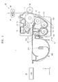
- FIG. 1 is a schematic diagram of an electrophotographic image forming apparatus 1 according to an embodiment.
- the electrophotographic image forming apparatus 1 according to an embodiment is a monochrome image forming apparatus using a two-component developing agent including a toner and a magnetic carrier as a developing agent.
- the toner may be, for example, black color.
- the electrophotographic image forming apparatus 1 includes a developing unit 10, an exposure unit 20, a transfer roller 30, and a fusing unit 40.
- the developing unit 10 includes a photosensitive drum 11, a charging roller 12, and a developer roller 13.
- the photosensitive drum 11 is an example of an image carrier, on which an electrostatic latent image is formed, and includes a photosensitive layer having a photoconductivity formed on an outer circumference of a cylindrical metal pipe.
- the charging roller 12 is an example of a charger for charging the photosensitive drum 11 to have uniform surface potential.
- a charging brush or a corona charger may be used instead of the charging roller 12.
- a cleaning roller 14 may remove foreign materials on a surface of the charging roller 12.
- the exposure unit 20 forms an electrostatic latent image on the photosensitive drum 11 by irradiating light modulated according to image information to the photosensitive drum 11.
- the exposure unit 20 may be a laser scanning unit (LSU) using a laser diode as a light source, or a light-emitting diode (LED) exposure unit using an LED as a light source.
- LSU laser scanning unit
- LED light-emitting diode
- the developer roller 13 supplies toner in a developing agent to the electrostatic latent image formed on the photosensitive drum 11 to form a visible toner image on the surface of the photosensitive drum 11.
- Reference numeral 16 indicates a regulating member for regulating an amount of toner adhered to a surface of the developer roller 13.
- the transfer roller 30 is an example of a transfer unit for transferring a toner image from the photosensitive drum 11 to a recording medium.
- a transfer bias voltage for transferring the toner image to the recording medium is applied to the transfer roller 30.
- a corona transfer unit or a transfer unit using a pin scorotron method may be used instead of the transfer roller 30.
- the toner remaining on the surface of the photosensitive drum 11 after the transfer is removed by a cleaning blade 15.
- the cleaning blade 15 is an example of a cleaning unit for removing toner and foreign materials on the surface of the photosensitive drum 11 after a transfer process.
- a cleaning apparatus having another shape, such as a rotating brush, may be used instead of the cleaning blade 15.
- the fusing unit 40 fuses a toner image transferred onto the recording medium on the recording medium.
- the fusing unit 40 includes a heating roller 41 and a pressing roller 42.
- the heating roller 41 is a member of a cylindrical shape that is rotatable in an axial direction of rotation, and includes a heat source, such as a halogen lamp, inside.
- the pressing roller 42 is a member of a cylindrical shape that is rotatable in an axial direction of rotation, and is provided to pressurize the heating roller 41.
- a heat-resistant layer including silicon rubber may be provided on outer circumferential surfaces of the heating roller 41 and the pressing roller 42.
- the toner image is fused on the recording medium by carrying the recording medium through a fusing nip that is a contacting region of the heating roller 41 and the pressing roller 42.
- an image signal of a recording image is transmitted to a control unit (not shown). Then, the control unit charges the surface of the photosensitive drum 11 to a uniform potential based on the received image signal by the charging roller 12, and then, forms an electrostatic latent image by irradiating laser light to the surface of the photosensitive drum 11 by the exposure unit 21.
- the developing unit 10 adheres a developing agent, which includes a toner and a carrier, to the developer roller 13, after sufficiently charging the developing agent by mixedly agitating toner and a carrier. Then, the toner in the developing agent adhered to the developer roller 13 moves to the photostatic latent image formed on an outer circumferential surface of the photosensitive drum 11 to form a toner image.
- the toner image formed like this is transferred onto the recording medium from the photosensitive drum 11 in a transfer nip formed by the photosensitive drum 11 and the transfer roller 30 facing each other.
- the recording medium onto which the toner image is transferred is conveyed to the fusing unit 40.
- the toner image is fused on the recording medium by passing the recording medium between the heating roller 41 and the pressing roller 42 while applying heat and pressure to the recording medium.
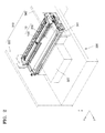
- FIG. 2 is a view illustrating a state in which a toner cartridge 200 and a developer cartridge 100 illustrated in FIG. 1 are completely mounted in a body frame 300.
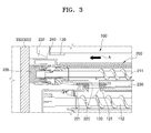
- FIG. 3 is a cross-sectional view of a portion of the toner cartridge 200 and the developer cartridge 100 of FIG. 2 , taken in a lengthwise direction of the photosensitive drum 11.
- the developing unit 10 includes the developer cartridge 100 and the toner cartridge 200.
- the developer cartridge 100 and the toner cartridge 200 are mounted such that an end in a lengthwise direction (a direction of an x-axis) is supported by the body frame 300.
- the developer cartridge 100 includes an agitating unit and a toner inlet 120, in addition to the photosensitive drum 11, the charging roller 12, and the developer roller 13 described above.
- the agitating unit of the developer cartridge 100 includes a region where the carrier and the toner are charged by agitating a magnetic carrier and a nonmagnetic or a soft magnetic toner included in the developing agent.
- the agitating unit of the developer cartridge 100 includes a first agitating member 111 and a second agitating member 112.
- the first agitating member 111 is arranged to face the developer roller 13 in an approximately vertical direction, and supplies the mixedly agitated developing agent to the developer roller 13.
- the second agitating member 112 serves to sufficiently charge the developing agent by mixedly agitating the developing agent, and conveys the charged developing agent to the first agitating member 111.
- the first and second agitating members 111 and 112 may be for example an auger having a rotation shaft extending in the lengthwise direction (the direction of the x-axis) of the developer roller 13 and a spiral wing formed on an outer circumference of the rotation shaft.
- the first and second agitating members 111 and 112 are arranged in parallel.
- a partition wall 113 is provided between the first agitating member 111 and the second agitating member 112.
- An opening is provided in the partition wall 113 so that the developing agent transported by the first agitating member 111 and the second agitating member 112 is connected at and passes through both ends of the first and second agitating members 111 and 112.
- the developing agent conveyed by the second agitating member 112 is conveyed to an outer circumferential surface of the developer roller 13 while being agitated and conveyed by the first agitating member 111.
- a toner concentration sensor (not shown) for detecting a concentration of the toner may be provided in the second agitating member 112, and, when the concentration of the toner in a conveyance path on which the toner is conveyed decreases, the toner is supplied from the toner cartridge 200 to the inside of the developer cartridge 100.
- the toner inlet 120 may be formed in a region where the second agitating member 112 is provided.
- the toner cartridge 200 contains the toner inside and is connected to the toner inlet 120 of the developer cartridge 100 to supply the toner.
- the toner cartridge 200 includes an agitating unit and a toner outlet 220.
- the agitating unit of the toner cartridge 200 includes a first agitating member 211 agitating and conveying the toner to the developer cartridge 100, and the agitating unit of the toner cartridge 200 includes a second agitating member 212 agitating and conveying the toner contained in the toner cartridge 200 to the first agitating member 211.
- the first agitating member 211 may for example be an auger including a rotation shaft extending in a lengthwise direction of the developer roller 13 and a spiral wing formed on an outer circumference of the rotation shaft.
- the second agitating member 212 may for example be a form having the rotation shaft and one or more agitating wings of a flexible film type on the rotation shaft.
- the toner contained in the toner cartridge 200 is conveyed to the first agitating member 211 by a rotation of the second agitating member 212 and the toner conveyed to the first agitating member 211 is conveyed to the toner outlet 220 by a rotation of the first agitating member 211.
- the toner outlet 220 may be formed in a region where the first agitating member 211 is provided.
- the toner outlet 220 is arranged in a location corresponding to the toner inlet 120 of the developer cartridge 100.
- the toner discharged through the toner outlet 220 is supplied to the inside of the developer cartridge 100 through the toner inlet 120.
- At least one sealing member may be arranged between the toner inlet 120 and the toner outlet 220 to seal therebetween.
- the toner cartridge 200 further includes a first sealing member 221 arranged in the toner outlet 220
- the developer cartridge 100 further includes a second sealing member 121 arranged in the toner inlet 120.
- the toner outlet 220 includes a region in which the first sealing member 221 is arranged
- the toner inlet 120 includes a region in which the second sealing member 121 is arranged.
- the developer cartridge 100 and the toner cartridge 200 are mounted in the body frame 300, and at least an end thereof is supported by the body frame 300.
- the developer cartridge 100 and the toner cartridge 200 are consumable products that are replaced when the lives thereof are expired.
- the lives of the developer cartridge 100 and the toner cartridge 200 may be different, and thus, a two-piece type may be used in which the developer cartridge 100 and the toner cartridge 200 are individually replaced from the body frame 300.
- the developer cartridge 100 and the toner cartridge 200 are individually replaced from the body frame 300, for example, when only the toner cartridge 200 is replaced, in a process of connecting the toner cartridge 200 to the developer cartridge 100 to supply the toner, the toner may leak.
- the developer cartridge 100 may be vulnerable to vibration. That is because the vibration of the toner cartridge 200 may be delivered to the developer cartridge 100.
- At least one first location regulating member 130 regulating a relative location of the toner cartridge 200 is provided in the developer cartridge 100 so that the toner outlet 220 of the toner cartridge 200 may be stably connected to the toner inlet 120 of the developer cartridge 100.
- at least one second location regulating member 332 regulating a relative location of the toner cartridge 200 is provided in the body frame 300 lest the vibration occurred in the toner cartridge 200 is delivered to the developer cartridge 100.
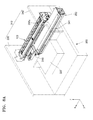
- FIG. 4 is a view illustrating a state in which the toner cartridge 200 is not yet mounted in the body frame 300.
- FIG. 5 is a perspective view of the toner cartridge 200 and the developer cartridge 100 of FIG. 4 , seen from a different angle.
- FIG. 4 does not illustrate a state in which the developer cartridge 100 is mounted/detached in/from the body frame 300, it will be understood that the developer cartridge 100 may be mounted/detached in/from the body frame 300 in the same direction as the toner cartridge 200.
- the developer cartridge 100 and the toner cartridge 200 may be mounted in the body frame 300 to be detachable.
- the toner cartridge 200 may be mounted along a mounting direction A and detached in a direction opposite to the mounting direction A.
- the mounting direction A may be a parallel direction to a lengthwise direction (a direction of an x-axis) of the photosensitive drum 11 or the developer roller 13 of the developer cartridge 100.
- the body frame 300 may include a side portion frame 310 arranged in both ends in a lengthwise direction of the developer cartridge 100 and the toner cartridge 200, and a bottom frame 320 supporting the weight of the developer cartridge 100 and the toner cartridge 200.
- the lengthwise direction of the developer cartridge 100 and the toner cartridge 200 is defined as a parallel direction to the mounting direction A of the developer cartridge 100 and the toner cartridge 200.
- the side portion frame 310 includes first and second side portion frames 330 and 340.
- the side portion frame 310 includes a supporting portion (not shown) supporting an end of the developer cartridge 100 and a supporting portion 331 supporting an end of the toner cartridge 200.
- FIG. 6 is a detailed view of a portion of FIG. 4 .
- the supporting portion 331 includes insertion holes 333 and 334 and couplers 335 and 336.
- a protrusion unit (not shown) formed in a lead in the mounting direction A of the toner cartridge 200 is inserted into the insertion holes 333 and 334 to support the end of the toner cartridge 200.
- the couplers 335 and 336 are connected to the first agitating member 211 and the second agitating member 212 of the toner cartridge 200 and deliver a driving force. That is, the supporting portion 331 delivers the driving force to the toner cartridge 200 while supporting the end of the toner cartridge 200.
- the first side portion frame 330 includes the second location regulating member 332 regulating a location of the toner cartridge 200.
- the second location regulating member 332 regulates a relative location of the toner cartridge 200 lest the toner cartridge 200 directly contacts the developer cartridge 100, while guiding the toner cartridge 200 to be connected to the supporting portion 331.
- the second location regulating member 332 regulates the location so that the toner outlet 220 of the toner cartridge 200 and the toner inlet 120 of the developer cartridge 100 are stably connected.
- the second side portion frame 230 may have an opening 341 through which the developer cartridge 100 and the toner cartridge 200 may pass for the mounting/ detachment of the developer cartridge 100 and the toner cartridge 200.
- the bottom frame 320 supports the weight of the toner cartridge 200 and the developer cartridge 100.
- the bottom frame 320 includes a first guide 321 guiding the mounting or detachment of the toner cartridge 200. As the toner cartridge 220 is guided by the first guide 321, the toner outlet 220 of the toner cartridge 200 may naturally draw to the toner inlet 120 of the developer cartridge 100.
- the bottom frame 320 includes a protrusion region 322 supporting the exposure unit 20 (refer to FIG. 1 ) irradiating light to the photosensitive drum 11 included in the developer cartridge 100.
- the developer cartridge 100 is mounted in the body frame 320 to be detachable.
- the developer cartridge 100 includes the toner inlet 120 for receiving the toner from the toner cartridge 200.
- the toner inlet 120 may be formed to be protruding in a cross direction to the mounting direction of the developer cartridge 100, for example a z direction.
- the developer cartridge 100 includes the first location regulating member 130 (refer to FIG. 5 ) regulating the location of the toner cartridge 200 with respect to the developer cartridge 100, when the toner outlet 220 of the toner cartridge 200 starts to overlap the toner inlet 120.
- the first location regulating member 130 prevents leakage of the toner by regulating a rise of the toner outlet 220 by the first and second sealing members 221 and 121.
- the first location regulating member 130 is formed in the developer cartridge 100 in which the toner inlet 120 is formed, the distance between the first location regulating member 130 and the toner inlet 120 may be stably maintained. If the first location regulating member 130 is formed in other member than the developer cartridge 100 in which the toner inlet 120 is formed, for example, the body frame 300, a size error and an assembling error of the components formed in the body frame 300 may occur, and thus, the distance between the first location regulating member 130 and the toner inlet 120 that are individually formed in different members may be hard to be maintained stably.
- the toner cartridge 200 includes an insertion portion 200a that is inserted into the developer cartridge 100.
- the toner outlet 220 discharging the toner of the toner cartridge 200, and a shutter 230 opening and closing the toner outlet 220 are formed in the insertion portion 200a.
- the developer cartridge 100 may have a groove 140 formed by extending along the mounting direction A so that the insertion portion 200a of the toner cartridge 100 may be inserted into the developer cartridge 100 and move along the mounting direction A.
- the developer cartridge 100 may have a cross-section, the shape of which in a vertical direction of the lengthwise direction (the direction of the x-axis) may be a 'C' shape.
- the toner outlet 220 formed in the insertion portion 200a is connected to the toner inlet 120 of the developer cartridge 100.
- the toner outlet 220 is formed such that the toner is discharged in a cross direction to the mounting direction of the toner cartridge 200, for example a vertical direction.
- the shutter 230 moves to open the toner outlet 220 in a process of mounting the toner cartridge 200 to the body frame 300.
- the toner cartridge 200 is connected to the body frame 300 to be detachable.
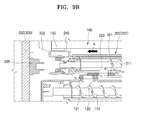
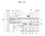
- the toner cartridge 200 is capable of moving to a first location 201 (refer to FIG. 9B ) where the toner cartridge 200 starts to connect to the developer cartridge 100 to supply the toner, and to a second location 202 (refer to FIG. 9C ) where the connection of the toner cartridge 200 and the developer cartridge 100 to supply the toner is completed.
- the toner cartridge 200 is completely mounted in the body frame 300, by sequentially moving from the first location 201 to the second location 202 along the mounting direction.
- the first location 201 is a location in which the toner outlet 220 of the toner cartridge 200 starts to overlap the toner inlet 120 of the developer cartridge 100.
- the second location 202 is a location in which the overlapping of the toner outlet 220 of the toner cartridge 200 and the toner inlet 120 of the developer cartridge 100 is completed.
- a connection state between the toner inlet 120 and the toner outlet 220 may warrant cautions. That is because when the toner cartridge 200 is located in the first location 201, the toner may leak by the first and second sealing members 221 and 121 arranged between the toner inlet 120 and the toner outlet 220. Also, when the toner cartridge 200 is located in the second location 202, if the toner cartridge 200 contacts the developer cartridge 100, the vibration of the toner cartridge 200 may be delivered to the developer cartridge 100.
- FIGS. 7A and 7B are views schematically illustrating a process in which the toner inlet 120 of the toner cartridge 200 overlaps the toner outlet 220 of the developer cartridge 100.
- the toner cartridge 200 moves along the mounting direction A.
- the shutter 230 moves along the mounting direction A with the toner cartridge 200.
- the shutter 230 moves along the mounting direction A with the toner cartridge 200 until the movement is limited by a contact with the toner inlet 120, and maintains a closing state of the toner outlet 220.
- the shutter 230 contacts the toner inlet 120 and the movement is limited. Referring to FIG.
- the toner outlet 220 is opened. That is, as the shutter 230 of the toner cartridge 200 relatively moves in a direction C opposite to the mounting direction A with respect to the toner outlet 220, the toner outlet 220 is opened. Accordingly, the toner outlet 220 and the toner inlet 120 start to overlap each other.
- the first and second sealing members 221 and 121 may be elastic members. Due to the elasticity of the first and second sealing members 221 and 121, an external force is applied to the toner cartridge 200 in a direction (B direction) in which the toner outlet 220 is drawn far from the toner inlet 120.
- the toner cartridge 200 to which the external force is applied may rise in the B direction temporarily or constantly. As a result, a gap between the toner outlet 220 and the toner inlet 120 may be generated, and the toner in the toner cartridge 200 may leak outside through the gap.
- the print image formed on the recording medium may be contaminated by the leaking toner, and a secondary fault may occur because the toner may contaminate the inside of the electrophotographic image forming apparatus 1.
- FIGS. 7A and 7B the description is made based on the example in which the first and second sealing members 221 and 121 are arranged between the toner inlet 120 and the toner outlet 220, but the configuration in which the problem occurs is not limited thereto, and the identical problem may occur also when the sealing member is singular or 3 or more.
- the location of the toner cartridge 200 with respect to the developer cartridge 100 is regulated by the first location regulating member 130 provided in the developer cartridge 100.
- the first location regulating member 130 may be formed in a section in a lengthwise direction (a direction of an x-axis) of the developer cartridge 100.
- the formation of the first location regulating member 130 is not limited thereto, and, although it is not shown in the drawings, the first location regulating member 130 may be formed throughout the entire section in the lengthwise direction (the direction of the x-axis) of the developer cartridge 100.
- FIGS. 8A through 8C are perspective views illustrating a process in which the toner cartridge 200 is mounted in the body frame 300 according to the mounting direction A.
- FIGS. 9A through 9C are partial cross-sectional views of a portion of FIGS. 8A through 8C , taken in a lengthwise direction of the photosensitive drum 11.
- the insertion portion 200a of the toner cartridge 200 moves along the mounting direction A while being inserted into the developer cartridge 100.
- the toner outlet 220 of the toner cartridge 200 is closed by the shutter 230, the discharging of the toner is limited.
- the toner cartridge 200 of FIG. 9A moves along the mounting direction A, the toner cartridge 200 is located in the first location 201, and the toner inlet 120 starts to overlap the toner outlet 220.
- the first location regulating member 130 contacts the contact region 240 of the toner cartridge 200 when the toner inlet 120 and the toner outlet 220 start to overlap each other, or before the toner inlet 120 and the toner outlet 220 start to overlap each other.
- the contact region 240 may be formed in a leading end in the mounting direction A of the toner cartridge 200.
- the first sealing member 221 arranged in the toner outlet 220 and the second sealing member 121 arranged in the toner inlet 120 contact each other, and thus, by the elasticity of the first and second sealing members 221 and 121, an external force is applied to the toner cartridge 200 in a direction in which the toner outlet 220 is drawn far from the toner inlet 120.
- the first location regulating member 130 contacts the contact region 240 of the toner cartridge 200, the location or the height of the toner cartridge 200 located in the first location 201 may be regulated, although the external force is applied to the toner cartridge 200 by the first and second sealing members 221 and 121.
- regulating of the location by the first location regulating member 130 is defined as regulating the location in a cross direction to the mounting direction A of the toner cartridge 200, for example a vertical direction (a direction of a z-axis.)
- FIGS. 8C and 9C as the toner cartridge 200 moves in the mounting direction A, an end of the toner cartridge 200 is combined to and supported by the first side portion frame 330.
- the coupler 335 is connected to the first agitating member 211 to deliver a driving force.
- the toner outlet 220 of the toner cartridge 200 is connected to the toner inlet 120 of the developer cartridge 100.
- FIG. 10 is a detailed view of a portion of FIG. 9C .
- the second location regulating member 332 regulates a location of the toner cartridge 200 with respect to the developer cartridge 100, when the toner cartridge 200 is located in the second location 202.
- the regulating of the location by the second location regulating member 130 and 332 is defined as regulating the location in a cross direction to the mounting direction A, for example, a vertical direction.
- the second location regulating member 332 regulates the location in a direction in which the toner outlet 220 of the toner cartridge 200 is drawn near to the toner inlet 120 of the developer cartridge 100 more than the first location regulating member 130 regulates the location in a direction in which the toner outlet 220 of the toner cartridge 200 is drawn near to the toner inlet 120 of the developer cartridge 100. Accordingly, the contact region 240 of the toner cartridge 200 and the first location regulating member 130 may be spaced apart from each other by a certain gap g.
- the first and second sealing members 221 and 121 arranged between the toner inlet 120 and the toner outlet 220 may be compressed more than when the contact region 240 contacts the first location regulating member 130.
- the second location regulating member 332 may be arranged closer to a vertical direction to the mounting direction A by a certain gap g than the first location regulating member 130 may be done.
- the toner cartridge 200 may be spaced apart from the developer cartridge 100. Since the toner cartridge 200 is spaced apart from the developer cartridge 100, even if the agitating unit of the toner cartridge 200 operates and generates vibration, the vibration may be prevented from being delivered to the developer cartridge 100 or may be minimized.
- the toner inlet 120 of the developer cartridge 100 and the toner outlet 220 of the toner cartridge 200 are indirectly connected by the sealing members 121 and 221. Due to elasticity of the sealing members 121 and 221, the vibration may be absorbed by the sealing members 121 and 221.
- FIG. 11 is a side view of the toner cartridge 200 and the developer cartridge 100 of FIG. 3 , seen from a right direction.
- FIG. 12 is a plan view of the toner cartridge 200 of FIG. 3 .
- the toner cartridge 200 is illustrated in dotted lines for convenience of explanation.
- the toner cartridge 200 may slide along the mounting direction A by being guided by the bottom frame 320 of the body frame 300 and the developer cartridge 100 in an early mounting process.
- a portion of the toner cartridge 200 may be inserted into the first guide 321 of the bottom frame 320 and the other portion of the toner cartridge 200 may be inserted into the second guide 141 of the developer cartridge 100.
- the toner cartridge 200 is inserted into a space formed by the bottom frame 320 and the developer cartridge 100 so that a bottom portion and a side portion of the toner cartridge 200 contacts the first guide 321 of the bottom frame 320 and a portion 250 of the insertion portion 200a of the toner cartridge 200 contacts the second guide 141 of the developer cartridge 100.
- the insertion portion 200a of the toner cartridge 200 contacts the second guide 141, but does not contact the groove 140.
- the toner cartridge 200 moves along the mounting direction A, the toner cartridge 200 is mounted to have one side portion supported by the first side portion frame 330, and the toner outlet 220 is connected to the toner inlet 120 of the developer cartridge 100.
- the first guide 321 of the bottom frame 320 supports the weight of the toner cartridge 200, and the second guide 141 of the developer cartridge 100 may drive a stable insertion of the insertion portion 200a of the toner cartridge 200 into the groove 140 of the developer cartridge 100.
- the insertion portion 200a may be stably inserted into the groove 140 of the developer cartridge 100 by the second guide 141, the leakage of the toner due to an unintentional opening of the shutter 230 as the insertion portion 200a of the toner cartridge 200 is mis-inserted into the groove 140 of the developer cartridge 100 may be prevented.
- the insertion portion 200a of the toner cartridge 200 may be formed in a section along the mounting direction A. As the insertion portion 200a is formed in the section, the toner cartridge 200 is guided by the second guide 141 contacting the toner cartridge 200 in an early mounting process, while after the toner cartridge 200 is mounted in the body frame 300, that is, when the toner cartridge 200 is located in the second location 202, the insertion portion 200a is released from the contact with the second guide 141. To this end, a section of the insertion portion 200a is formed in a lead in the mounting direction A of the toner cartridge 200, and is not formed in a rear of the mounting direction A.
- the toner leakage outside may be prevented by regulating the locations of the developer cartridge 100 and the toner cartridge 200 within a consistent margin or error in a process of connecting the developer cartridge 100 and the toner cartridge 200. Also, when the developer cartridge 100 and the toner cartridge 200 are completely connected to each other, the vibration generated in the toner cartridge 200 may be prevented from having effects on the developer cartridge 100.
Landscapes
- Physics & Mathematics (AREA)
- General Physics & Mathematics (AREA)
- Engineering & Computer Science (AREA)
- Computer Vision & Pattern Recognition (AREA)
- Dry Development In Electrophotography (AREA)
- Electrophotography Configuration And Component (AREA)
Abstract
Description
- This application claims the priority benefit of
U.S. Provisional Application No. 61/873,045, filed on September 3, 2013 10-2013-0124151, filed on October 17, 2013 - One or more embodiments of the present disclosure relate to an electrophotographic image forming apparatus, and more particularly, to an electrophotographic image forming apparatus capable of guaranteeing a stable connection of a developer (development) cartridge and a toner cartridge in a mounting process and minimizing effect due to vibration when mounted.
- Image forming apparatuses are apparatuses forming an image on a recording medium according to signals that are input, and the image forming apparatuses include printers, photocopiers, fax machines, and multi-function peripherals realized by integrating functions of the printers, the photocopiers, and the fax machines.
- Image forming apparatuses are configured by including a body loading or supplying paper and supporting or driving various components in the image forming apparatuses, and a developing unit mounted in the body and forming an image on the paper.
- The developing unit may be classified as a one-piece way or a two-piece way according to a print speed, a developing method, and a system layout. The one-piece way is a way in which a portion forming an image and a portion supplying toner are not separated but prepared in one developing unit. The two-piece way is a way in which the portion forming the image and the portion supplying the toner are separated as a developer cartridge and a toner cartridge respectively and mounted in a body of the image forming apparatuses additionally.
- In general, in the case of the developing unit of the two-piece way, the developing unit has a structure in which toner contained in the toner cartridge is supplied to the developer cartridge. Here, when a relative location relationship between the developer cartridge and the toner cartridge is not regulated within a consistent margin of error, the toner may not smoothly be supplied or may leak outside the developer cartridge or the toner cartridge, when the toner is transported from the toner cartridge to the developer cartridge.
- According to the present invention there is provided an apparatus and method as set forth in the appended claims. Other features of the invention will be apparent from the dependent claims, and the description which follows.
- In an aspect of one or more embodiments, there is provided an electrophotographic image forming apparatus which has an improved structure in which a location of a toner cartridge is regulated within a consistent margin of error while the toner cartridge is mounted in a body to be connected to a developer cartridge, and, the toner cartridge and the developer cartridge may be spaced apart from each other after the toner cartridge is completely mounted in the body.
- In an aspect of one or more embodiments, there is provided an electrophotographic image forming apparatus which includes: a body frame; a developer cartridge mounted in the body frame to be detachable; a toner cartridge mounted in the body frame to be detachable, and capable of moving to a first location where the toner cartridge starts to connect to the developer cartridge to supply toner and to a second location where the connection of the toner cartridge and the developer cartridge to supply the toner is completed; at least one first location regulating member provided in the developer cartridge, and regulating a relative location of the toner cartridge with respect to the developer cartridge when the toner cartridge is located in the first location; and at least one second location regulating member provided in the body frame, and regulating a relative location of the toner cartridge with respect to the developer cartridge so that the toner cartridge is spaced apart from the at least one first location regulating member when the toner cartridge is located in the second location.
- The developer cartridge may include a toner inlet, and the toner cartridge may include a toner outlet corresponding to the toner inlet to supply the toner to the developer cartridge and a shutter for opening and closing the toner outlet.
- A sealing member sealing between the toner inlet and the toner outlet may be formed in at least one of the toner inlet and the toner outlet.
- The first location may be a location where the toner outlet starts to overlap the toner inlet.
- The second location may be a location where overlapping of the toner outlet and the toner inlet is completed.
- The second location may be a location where the toner cartridge is completely mounted in the body frame.
- The at least one first location regulating member may contact the toner cartridge, when the toner inlet and the toner outlet start to overlap each other, or before the toner inlet and the toner outlet start to overlap each other.
- The at least one first location regulating member may be released from the contact with the toner cartridge, when overlapping of the toner inlet and the toner outlet is completed.
- The toner cartridge may include a contact region that sequentially contacts the at least one first location regulating member and the at least one second location regulating member along a mounting direction, while the toner cartridge is mounted in the body frame.
- The contact region may be formed in a leading end in the mounting direction of the toner cartridge.
- The at least one second location regulating member may be arranged such that the toner outlet is drawn near to the toner inlet more than the at least one first location regulating member may be arranged such that the toner outlet is drawn near to the toner inlet.
- The body frame may include a side portion frame supporting at least an end of the developer cartridge and the toner cartridge, and a bottom frame supporting a bottom of the toner cartridge and comprising a first guide guiding a slide movement of the toner cartridge.
- The developer cartridge may include a second guide guiding a slide movement of the toner cartridge.
- The toner cartridge may be released from a contact with the second guide, when the toner cartridge is in the second location.
- The toner cartridge may be mounted in the body frame in a parallel direction to a lengthwise direction of the developer cartridge.
- In an aspect of one or more embodiments, there is provided an electrophotographic image forming apparatus which includes an electrophotographic image forming apparatus including a body frame; a developer cartridge mounted in the body frame to be detachable; a toner cartridge mounted in the body frame to be detachable, and configured to move to a first location where the toner cartridge starts to connect to the developer cartridge to supply toner and to a second location where the connection of the toner cartridge and the developer cartridge to supply the toner is completed; at least one first location regulating member provided in the developer cartridge, and regulating a relative location of the toner cartridge with respect to the developer cartridge when the toner cartridge is located in the first location; and at least one second location regulating member provided in the body frame, and regulating a relative location of the toner cartridge with respect to the developer cartridge so that the toner cartridge is spaced apart from the at least one first location regulating member when the toner cartridge is located in the second location.
- In an aspect of one or more embodiments, there is provided an electrophotographic image forming apparatus which includes a body frame; a developer cartridge mounted in the body frame to be detachable and including a photosensitive drum upon which the electrostatic latent image is formed; an exposure unit to form the electrostatic latent image on the photosensitive drum; a toner cartridge mounted in the body frame to be detachable, and configured to move to a first location where the toner cartridge starts to connect to the developer cartridge to supply toner and to a second location where the connection of the toner cartridge and the developer cartridge to supply the toner is completed; at least one first location regulating member provided in the developer cartridge, and regulating a relative location of the toner cartridge with respect to the developer cartridge when the toner cartridge is located in the first location; and at least one second location regulating member provided in the body frame, and regulating a relative location of the toner cartridge with respect to the developer cartridge so that the toner cartridge is spaced apart from the at least one first location regulating member when the toner cartridge is located in the second location; a transfer roller to transfer a toner image formed on the photosensitive drum from the photosensitive drum to a recording medium; and a fusing unit to fuse the toner image transferred to the recording medium on the recording medium.
- These and/or other aspects will become apparent and more readily appreciated from the following description of embodiments, taken in conjunction with the accompanying drawings in which:
-
FIG. 1 is a schematic block diagram of an electrophotographic image forming apparatus according to an embodiment; -
FIG. 2 is a view illustrating a state in which a toner cartridge and a developer cartridge illustrated inFIG. 1 are mounted in a body frame; -
FIG. 3 is a cross-sectional view of a portion of the toner cartridge and the developer cartridge ofFIG. 2 , taken in a lengthwise direction of a photosensitive drum; -
FIG. 4 is a view illustrating a state in which a toner cartridge is not yet mounted in a body frame; -
FIG. 5 is a perspective view of the toner cartridge and the developer cartridge ofFIG. 4 , seen from a different angle; -
FIG. 6 is a detailed view of a portion ofFIG. 4 ; -
FIGS. 7A and 7B are views schematically illustrating a process in which a toner receiving unit of a toner cartridge overlaps a toner outlet of a developer cartridge; -
FIGS. 8A through 8C are perspective views illustrating a process in which a toner cartridge is mounted in a body frame according to a mounting direction; -
FIGS. 9A through 9C are partial cross-sectional views of a portion ofFIGS. 8A through 8C , taken in a lengthwise direction of a photosensitive drum; -
FIG. 10 is a detailed view of a portion ofFIG. 9C ; -
FIG. 11 is a side view of the toner cartridge and the developer cartridge ofFIG. 3 , seen from a right direction; and -
FIG. 12 is a plan view of the toner cartridge ofFIG. 3 . - Reference will now be made in detail to embodiments, examples of which are illustrated in the accompanying drawings, wherein like reference numerals refer to the like elements throughout. In this regard, embodiments may have different forms and should not be construed as being limited to the descriptions set forth herein. Accordingly, embodiments are merely described below, by referring to the figures, to explain aspects of the present description. Expressions such as "at least one of," when preceding a list of elements, modify the entire list of elements and do not modify the individual elements of the list.
-
FIG. 1 is a schematic diagram of an electrophotographicimage forming apparatus 1 according to an embodiment. The electrophotographicimage forming apparatus 1 according to an embodiment is a monochrome image forming apparatus using a two-component developing agent including a toner and a magnetic carrier as a developing agent. The toner may be, for example, black color. - Referring to
FIG. 1 , the electrophotographicimage forming apparatus 1 according to an embodiment includes a developingunit 10, anexposure unit 20, atransfer roller 30, and afusing unit 40. The developingunit 10 includes aphotosensitive drum 11, acharging roller 12, and adeveloper roller 13. - The
photosensitive drum 11 is an example of an image carrier, on which an electrostatic latent image is formed, and includes a photosensitive layer having a photoconductivity formed on an outer circumference of a cylindrical metal pipe. - The charging
roller 12 is an example of a charger for charging thephotosensitive drum 11 to have uniform surface potential. A charging brush or a corona charger may be used instead of the chargingroller 12. A cleaningroller 14 may remove foreign materials on a surface of the chargingroller 12. - The
exposure unit 20 forms an electrostatic latent image on thephotosensitive drum 11 by irradiating light modulated according to image information to thephotosensitive drum 11. Theexposure unit 20 may be a laser scanning unit (LSU) using a laser diode as a light source, or a light-emitting diode (LED) exposure unit using an LED as a light source. - The
developer roller 13 supplies toner in a developing agent to the electrostatic latent image formed on thephotosensitive drum 11 to form a visible toner image on the surface of thephotosensitive drum 11.Reference numeral 16 indicates a regulating member for regulating an amount of toner adhered to a surface of thedeveloper roller 13. - The
transfer roller 30 is an example of a transfer unit for transferring a toner image from thephotosensitive drum 11 to a recording medium. A transfer bias voltage for transferring the toner image to the recording medium is applied to thetransfer roller 30. A corona transfer unit or a transfer unit using a pin scorotron method may be used instead of thetransfer roller 30. The toner remaining on the surface of thephotosensitive drum 11 after the transfer is removed by acleaning blade 15. Thecleaning blade 15 is an example of a cleaning unit for removing toner and foreign materials on the surface of thephotosensitive drum 11 after a transfer process. A cleaning apparatus having another shape, such as a rotating brush, may be used instead of thecleaning blade 15. - The fusing
unit 40 fuses a toner image transferred onto the recording medium on the recording medium. The fusingunit 40 includes aheating roller 41 and apressing roller 42. Theheating roller 41 is a member of a cylindrical shape that is rotatable in an axial direction of rotation, and includes a heat source, such as a halogen lamp, inside. Thepressing roller 42 is a member of a cylindrical shape that is rotatable in an axial direction of rotation, and is provided to pressurize theheating roller 41. A heat-resistant layer including silicon rubber may be provided on outer circumferential surfaces of theheating roller 41 and thepressing roller 42. The toner image is fused on the recording medium by carrying the recording medium through a fusing nip that is a contacting region of theheating roller 41 and thepressing roller 42. - An operation of the electrophotographic
image forming apparatus 1 configured as such will be described. - When the electrophotographic
image forming apparatus 1 operates, an image signal of a recording image is transmitted to a control unit (not shown). Then, the control unit charges the surface of thephotosensitive drum 11 to a uniform potential based on the received image signal by the chargingroller 12, and then, forms an electrostatic latent image by irradiating laser light to the surface of thephotosensitive drum 11 by the exposure unit 21. - The developing
unit 10 adheres a developing agent, which includes a toner and a carrier, to thedeveloper roller 13, after sufficiently charging the developing agent by mixedly agitating toner and a carrier. Then, the toner in the developing agent adhered to thedeveloper roller 13 moves to the photostatic latent image formed on an outer circumferential surface of thephotosensitive drum 11 to form a toner image. The toner image formed like this is transferred onto the recording medium from thephotosensitive drum 11 in a transfer nip formed by thephotosensitive drum 11 and thetransfer roller 30 facing each other. - The recording medium onto which the toner image is transferred is conveyed to the
fusing unit 40. The toner image is fused on the recording medium by passing the recording medium between theheating roller 41 and thepressing roller 42 while applying heat and pressure to the recording medium. - Next, a structure and operation of the developing
unit 10 according to an embodiment will be described. -
FIG. 2 is a view illustrating a state in which atoner cartridge 200 and adeveloper cartridge 100 illustrated inFIG. 1 are completely mounted in abody frame 300.FIG. 3 is a cross-sectional view of a portion of thetoner cartridge 200 and thedeveloper cartridge 100 ofFIG. 2 , taken in a lengthwise direction of thephotosensitive drum 11. - Referring to
FIGS. 1 through 3 , the developingunit 10 includes thedeveloper cartridge 100 and thetoner cartridge 200. Thedeveloper cartridge 100 and thetoner cartridge 200 are mounted such that an end in a lengthwise direction (a direction of an x-axis) is supported by thebody frame 300. - The
developer cartridge 100 includes an agitating unit and atoner inlet 120, in addition to thephotosensitive drum 11, the chargingroller 12, and thedeveloper roller 13 described above. - The agitating unit of the
developer cartridge 100 includes a region where the carrier and the toner are charged by agitating a magnetic carrier and a nonmagnetic or a soft magnetic toner included in the developing agent. The agitating unit of thedeveloper cartridge 100 includes a first agitatingmember 111 and a second agitatingmember 112. - The first agitating
member 111 is arranged to face thedeveloper roller 13 in an approximately vertical direction, and supplies the mixedly agitated developing agent to thedeveloper roller 13. The second agitatingmember 112 serves to sufficiently charge the developing agent by mixedly agitating the developing agent, and conveys the charged developing agent to the first agitatingmember 111. The first and second agitatingmembers developer roller 13 and a spiral wing formed on an outer circumference of the rotation shaft. - The first and second agitating
members partition wall 113 is provided between the first agitatingmember 111 and the second agitatingmember 112. An opening (not shown) is provided in thepartition wall 113 so that the developing agent transported by the first agitatingmember 111 and the second agitatingmember 112 is connected at and passes through both ends of the first and second agitatingmembers - The developing agent conveyed by the second agitating
member 112 is conveyed to an outer circumferential surface of thedeveloper roller 13 while being agitated and conveyed by the first agitatingmember 111. A toner concentration sensor (not shown) for detecting a concentration of the toner may be provided in the second agitatingmember 112, and, when the concentration of the toner in a conveyance path on which the toner is conveyed decreases, the toner is supplied from thetoner cartridge 200 to the inside of thedeveloper cartridge 100. Thetoner inlet 120 may be formed in a region where the second agitatingmember 112 is provided. - The
toner cartridge 200 contains the toner inside and is connected to thetoner inlet 120 of thedeveloper cartridge 100 to supply the toner. Thetoner cartridge 200 includes an agitating unit and atoner outlet 220. - The agitating unit of the
toner cartridge 200 includes a first agitatingmember 211 agitating and conveying the toner to thedeveloper cartridge 100, and the agitating unit of thetoner cartridge 200 includes a second agitatingmember 212 agitating and conveying the toner contained in thetoner cartridge 200 to the first agitatingmember 211. The first agitatingmember 211 may for example be an auger including a rotation shaft extending in a lengthwise direction of thedeveloper roller 13 and a spiral wing formed on an outer circumference of the rotation shaft. The second agitatingmember 212 may for example be a form having the rotation shaft and one or more agitating wings of a flexible film type on the rotation shaft. The toner contained in thetoner cartridge 200 is conveyed to the first agitatingmember 211 by a rotation of the second agitatingmember 212 and the toner conveyed to the first agitatingmember 211 is conveyed to thetoner outlet 220 by a rotation of the first agitatingmember 211. - The
toner outlet 220 may be formed in a region where the first agitatingmember 211 is provided. Thetoner outlet 220 is arranged in a location corresponding to thetoner inlet 120 of thedeveloper cartridge 100. The toner discharged through thetoner outlet 220 is supplied to the inside of thedeveloper cartridge 100 through thetoner inlet 120. - At least one sealing member may be arranged between the
toner inlet 120 and thetoner outlet 220 to seal therebetween. For example, thetoner cartridge 200 further includes afirst sealing member 221 arranged in thetoner outlet 220, and thedeveloper cartridge 100 further includes asecond sealing member 121 arranged in thetoner inlet 120. Thetoner outlet 220 includes a region in which thefirst sealing member 221 is arranged, and thetoner inlet 120 includes a region in which thesecond sealing member 121 is arranged. - The
developer cartridge 100 and thetoner cartridge 200 are mounted in thebody frame 300, and at least an end thereof is supported by thebody frame 300. Thedeveloper cartridge 100 and thetoner cartridge 200 are consumable products that are replaced when the lives thereof are expired. The lives of thedeveloper cartridge 100 and thetoner cartridge 200 may be different, and thus, a two-piece type may be used in which thedeveloper cartridge 100 and thetoner cartridge 200 are individually replaced from thebody frame 300. When thedeveloper cartridge 100 and thetoner cartridge 200 are individually replaced from thebody frame 300, for example, when only thetoner cartridge 200 is replaced, in a process of connecting thetoner cartridge 200 to thedeveloper cartridge 100 to supply the toner, the toner may leak. When the connection of thetoner cartridge 200 to thedeveloper cartridge 100 is completed, if thetoner cartridge 200 and thedeveloper cartridge 100 directly contact each other, thedeveloper cartridge 100 may be vulnerable to vibration. That is because the vibration of thetoner cartridge 200 may be delivered to thedeveloper cartridge 100. - According to an embodiment, in a process of mounting the
toner cartridge 200 in thebody frame 300, at least one firstlocation regulating member 130 regulating a relative location of thetoner cartridge 200 is provided in thedeveloper cartridge 100 so that thetoner outlet 220 of thetoner cartridge 200 may be stably connected to thetoner inlet 120 of thedeveloper cartridge 100. Also, at least one secondlocation regulating member 332 regulating a relative location of thetoner cartridge 200 is provided in thebody frame 300 lest the vibration occurred in thetoner cartridge 200 is delivered to thedeveloper cartridge 100. - Hereinafter, a connection relationship of the
developer cartridge 100, thetoner cartridge 200, and thebody frame 300 will be described by referring toFIGS. 4 through 9 , and, characteristics of the firstlocation regulating member 130 provided in thedeveloper cartridge 100 and the secondlocation regulating member 332 provided in thebody frame 300 will be described in detail in this connection relationship. -
FIG. 4 is a view illustrating a state in which thetoner cartridge 200 is not yet mounted in thebody frame 300.FIG. 5 is a perspective view of thetoner cartridge 200 and thedeveloper cartridge 100 ofFIG. 4 , seen from a different angle. AlthoughFIG. 4 does not illustrate a state in which thedeveloper cartridge 100 is mounted/detached in/from thebody frame 300, it will be understood that thedeveloper cartridge 100 may be mounted/detached in/from thebody frame 300 in the same direction as thetoner cartridge 200. - Referring to
FIGS. 4 through 5 , thedeveloper cartridge 100 and thetoner cartridge 200 may be mounted in thebody frame 300 to be detachable. For example, thetoner cartridge 200 may be mounted along a mounting direction A and detached in a direction opposite to the mounting direction A. The mounting direction A may be a parallel direction to a lengthwise direction (a direction of an x-axis) of thephotosensitive drum 11 or thedeveloper roller 13 of thedeveloper cartridge 100. - The
body frame 300 may include aside portion frame 310 arranged in both ends in a lengthwise direction of thedeveloper cartridge 100 and thetoner cartridge 200, and abottom frame 320 supporting the weight of thedeveloper cartridge 100 and thetoner cartridge 200. Here, the lengthwise direction of thedeveloper cartridge 100 and thetoner cartridge 200 is defined as a parallel direction to the mounting direction A of thedeveloper cartridge 100 and thetoner cartridge 200. - The
side portion frame 310 includes first and second side portion frames 330 and 340. Theside portion frame 310 includes a supporting portion (not shown) supporting an end of thedeveloper cartridge 100 and a supportingportion 331 supporting an end of thetoner cartridge 200.FIG. 6 is a detailed view of a portion ofFIG. 4 . Referring toFIG. 6 , the supportingportion 331 includes insertion holes 333 and 334 andcouplers toner cartridge 200 is inserted into the insertion holes 333 and 334 to support the end of thetoner cartridge 200. Thecouplers member 211 and the second agitatingmember 212 of thetoner cartridge 200 and deliver a driving force. That is, the supportingportion 331 delivers the driving force to thetoner cartridge 200 while supporting the end of thetoner cartridge 200. - The first
side portion frame 330 includes the secondlocation regulating member 332 regulating a location of thetoner cartridge 200. The secondlocation regulating member 332 regulates a relative location of thetoner cartridge 200 lest thetoner cartridge 200 directly contacts thedeveloper cartridge 100, while guiding thetoner cartridge 200 to be connected to the supportingportion 331. In addition, the secondlocation regulating member 332 regulates the location so that thetoner outlet 220 of thetoner cartridge 200 and thetoner inlet 120 of thedeveloper cartridge 100 are stably connected. - The second
side portion frame 230 may have anopening 341 through which thedeveloper cartridge 100 and thetoner cartridge 200 may pass for the mounting/ detachment of thedeveloper cartridge 100 and thetoner cartridge 200. - The
bottom frame 320 supports the weight of thetoner cartridge 200 and thedeveloper cartridge 100. Thebottom frame 320 includes afirst guide 321 guiding the mounting or detachment of thetoner cartridge 200. As thetoner cartridge 220 is guided by thefirst guide 321, thetoner outlet 220 of thetoner cartridge 200 may naturally draw to thetoner inlet 120 of thedeveloper cartridge 100. Thebottom frame 320 includes aprotrusion region 322 supporting the exposure unit 20 (refer toFIG. 1 ) irradiating light to thephotosensitive drum 11 included in thedeveloper cartridge 100. - The
developer cartridge 100 is mounted in thebody frame 320 to be detachable. Thedeveloper cartridge 100 includes thetoner inlet 120 for receiving the toner from thetoner cartridge 200. Thetoner inlet 120 may be formed to be protruding in a cross direction to the mounting direction of thedeveloper cartridge 100, for example a z direction. - The
developer cartridge 100 includes the first location regulating member 130 (refer toFIG. 5 ) regulating the location of thetoner cartridge 200 with respect to thedeveloper cartridge 100, when thetoner outlet 220 of thetoner cartridge 200 starts to overlap thetoner inlet 120. The firstlocation regulating member 130 prevents leakage of the toner by regulating a rise of thetoner outlet 220 by the first andsecond sealing members - Since the first
location regulating member 130 is formed in thedeveloper cartridge 100 in which thetoner inlet 120 is formed, the distance between the firstlocation regulating member 130 and thetoner inlet 120 may be stably maintained. If the firstlocation regulating member 130 is formed in other member than thedeveloper cartridge 100 in which thetoner inlet 120 is formed, for example, thebody frame 300, a size error and an assembling error of the components formed in thebody frame 300 may occur, and thus, the distance between the firstlocation regulating member 130 and thetoner inlet 120 that are individually formed in different members may be hard to be maintained stably. - The
toner cartridge 200 includes aninsertion portion 200a that is inserted into thedeveloper cartridge 100. Thetoner outlet 220 discharging the toner of thetoner cartridge 200, and ashutter 230 opening and closing thetoner outlet 220 are formed in theinsertion portion 200a. Thedeveloper cartridge 100 may have agroove 140 formed by extending along the mounting direction A so that theinsertion portion 200a of thetoner cartridge 100 may be inserted into thedeveloper cartridge 100 and move along the mounting direction A. For example, thedeveloper cartridge 100 may have a cross-section, the shape of which in a vertical direction of the lengthwise direction (the direction of the x-axis) may be a 'C' shape. - As the
toner cartridge 200 moves along the mounting direction A in a state that theinsertion portion 200a of thetoner cartridge 200 is inserted into thegroove 140 of thedeveloper cartridge 100, thetoner outlet 220 formed in theinsertion portion 200a is connected to thetoner inlet 120 of thedeveloper cartridge 100. Thetoner outlet 220 is formed such that the toner is discharged in a cross direction to the mounting direction of thetoner cartridge 200, for example a vertical direction. Theshutter 230 moves to open thetoner outlet 220 in a process of mounting thetoner cartridge 200 to thebody frame 300. - The
toner cartridge 200 is connected to thebody frame 300 to be detachable. Thetoner cartridge 200 is capable of moving to a first location 201 (refer toFIG. 9B ) where thetoner cartridge 200 starts to connect to thedeveloper cartridge 100 to supply the toner, and to a second location 202 (refer toFIG. 9C ) where the connection of thetoner cartridge 200 and thedeveloper cartridge 100 to supply the toner is completed. Thetoner cartridge 200 is completely mounted in thebody frame 300, by sequentially moving from thefirst location 201 to thesecond location 202 along the mounting direction. Thefirst location 201 is a location in which thetoner outlet 220 of thetoner cartridge 200 starts to overlap thetoner inlet 120 of thedeveloper cartridge 100. Thesecond location 202 is a location in which the overlapping of thetoner outlet 220 of thetoner cartridge 200 and thetoner inlet 120 of thedeveloper cartridge 100 is completed. - In a process of mounting the
toner cartridge 200 in thebody frame 300, when thetoner cartridge 200 is located in thefirst location 201 or thesecond location 202, a connection state between thetoner inlet 120 and thetoner outlet 220 may warrant cautions. That is because when thetoner cartridge 200 is located in thefirst location 201, the toner may leak by the first andsecond sealing members toner inlet 120 and thetoner outlet 220. Also, when thetoner cartridge 200 is located in thesecond location 202, if thetoner cartridge 200 contacts thedeveloper cartridge 100, the vibration of thetoner cartridge 200 may be delivered to thedeveloper cartridge 100. -
FIGS. 7A and 7B are views schematically illustrating a process in which thetoner inlet 120 of thetoner cartridge 200 overlaps thetoner outlet 220 of thedeveloper cartridge 100. Referring toFIG. 7A , thetoner cartridge 200 moves along the mounting direction A. Theshutter 230 moves along the mounting direction A with thetoner cartridge 200. Theshutter 230 moves along the mounting direction A with thetoner cartridge 200 until the movement is limited by a contact with thetoner inlet 120, and maintains a closing state of thetoner outlet 220. Then, as thetoner cartridge 200 moves along the mounting direction A, theshutter 230 contacts thetoner inlet 120 and the movement is limited. Referring toFIG. 7B , as thetoner cartridge 200 moves along the mounting direction A in the state in which the movement of theshutter 230 is limited, thetoner outlet 220 is opened. That is, as theshutter 230 of thetoner cartridge 200 relatively moves in a direction C opposite to the mounting direction A with respect to thetoner outlet 220, thetoner outlet 220 is opened. Accordingly, thetoner outlet 220 and thetoner inlet 120 start to overlap each other. - When the
toner outlet 220 and thetoner inlet 120 start to overlap each other, thefirst sealing member 221 arranged in thetoner outlet 220 and thesecond sealing member 121 arranged in thetoner inlet 120 contact each other. The first andsecond sealing members second sealing members toner cartridge 200 in a direction (B direction) in which thetoner outlet 220 is drawn far from thetoner inlet 120. Thetoner cartridge 200 to which the external force is applied may rise in the B direction temporarily or constantly. As a result, a gap between thetoner outlet 220 and thetoner inlet 120 may be generated, and the toner in thetoner cartridge 200 may leak outside through the gap. The print image formed on the recording medium may be contaminated by the leaking toner, and a secondary fault may occur because the toner may contaminate the inside of the electrophotographicimage forming apparatus 1. InFIGS. 7A and 7B , the description is made based on the example in which the first andsecond sealing members toner inlet 120 and thetoner outlet 220, but the configuration in which the problem occurs is not limited thereto, and the identical problem may occur also when the sealing member is singular or 3 or more. - According to an embodiment, when the
toner cartridge 200 is located in thefirst location 201 where thetoner cartridge 200 starts to connect to thedeveloper cartridge 100 to supply the toner, the location of thetoner cartridge 200 with respect to thedeveloper cartridge 100 is regulated by the firstlocation regulating member 130 provided in thedeveloper cartridge 100. The firstlocation regulating member 130 may be formed in a section in a lengthwise direction (a direction of an x-axis) of thedeveloper cartridge 100. However, the formation of the firstlocation regulating member 130 is not limited thereto, and, although it is not shown in the drawings, the firstlocation regulating member 130 may be formed throughout the entire section in the lengthwise direction (the direction of the x-axis) of thedeveloper cartridge 100. -
FIGS. 8A through 8C are perspective views illustrating a process in which thetoner cartridge 200 is mounted in thebody frame 300 according to the mounting direction A.FIGS. 9A through 9C are partial cross-sectional views of a portion ofFIGS. 8A through 8C , taken in a lengthwise direction of thephotosensitive drum 11. - Referring to
FIGS. 8A and9A , theinsertion portion 200a of thetoner cartridge 200 moves along the mounting direction A while being inserted into thedeveloper cartridge 100. Here, since thetoner outlet 220 of thetoner cartridge 200 is closed by theshutter 230, the discharging of the toner is limited. - Referring to
FIGS. 8B and9B , as thetoner cartridge 200 ofFIG. 9A moves along the mounting direction A, thetoner cartridge 200 is located in thefirst location 201, and thetoner inlet 120 starts to overlap thetoner outlet 220. The firstlocation regulating member 130 contacts thecontact region 240 of thetoner cartridge 200 when thetoner inlet 120 and thetoner outlet 220 start to overlap each other, or before thetoner inlet 120 and thetoner outlet 220 start to overlap each other. Thecontact region 240 may be formed in a leading end in the mounting direction A of thetoner cartridge 200. As thetoner inlet 120 starts to overlap thetoner outlet 220, thefirst sealing member 221 arranged in thetoner outlet 220 and thesecond sealing member 121 arranged in thetoner inlet 120 contact each other, and thus, by the elasticity of the first andsecond sealing members toner cartridge 200 in a direction in which thetoner outlet 220 is drawn far from thetoner inlet 120. Here, since the firstlocation regulating member 130 contacts thecontact region 240 of thetoner cartridge 200, the location or the height of thetoner cartridge 200 located in thefirst location 201 may be regulated, although the external force is applied to thetoner cartridge 200 by the first andsecond sealing members toner outlet 220 and thetoner inlet 120 may be prevented in the mounting process of thetoner cartridge 200, thereby preventing the toner from leaking outside. Here, regulating of the location by the firstlocation regulating member 130 is defined as regulating the location in a cross direction to the mounting direction A of thetoner cartridge 200, for example a vertical direction (a direction of a z-axis.) - When the mounting of the
toner cartridge 200 is completed, that is, when thetoner cartridge 200 is located in thesecond location 202, the contact of the firstlocation regulating member 130 and thetoner cartridge 200 is released. By this, vibration generated in thetoner cartridge 200 may be prevented from being delivered to thedeveloper cartridge 100 along the firstlocation regulating member 130. - Referring to
FIGS. 8C and9C , as thetoner cartridge 200 moves in the mounting direction A, an end of thetoner cartridge 200 is combined to and supported by the firstside portion frame 330. Thecoupler 335 is connected to the first agitatingmember 211 to deliver a driving force. Thetoner outlet 220 of thetoner cartridge 200 is connected to thetoner inlet 120 of thedeveloper cartridge 100.FIG. 10 is a detailed view of a portion ofFIG. 9C . Referring toFIGS. 9C and10 , the secondlocation regulating member 332 regulates a location of thetoner cartridge 200 with respect to thedeveloper cartridge 100, when thetoner cartridge 200 is located in thesecond location 202. Here, the regulating of the location by the secondlocation regulating member - The second
location regulating member 332 regulates the location in a direction in which thetoner outlet 220 of thetoner cartridge 200 is drawn near to thetoner inlet 120 of thedeveloper cartridge 100 more than the firstlocation regulating member 130 regulates the location in a direction in which thetoner outlet 220 of thetoner cartridge 200 is drawn near to thetoner inlet 120 of thedeveloper cartridge 100. Accordingly, thecontact region 240 of thetoner cartridge 200 and the firstlocation regulating member 130 may be spaced apart from each other by a certain gap g. Here, the first andsecond sealing members toner inlet 120 and thetoner outlet 220 may be compressed more than when thecontact region 240 contacts the firstlocation regulating member 130. The secondlocation regulating member 332 may be arranged closer to a vertical direction to the mounting direction A by a certain gap g than the firstlocation regulating member 130 may be done. - As the
toner cartridge 200 and the firstlocation regulating member 130 are spaced apart, thetoner cartridge 200 may be spaced apart from thedeveloper cartridge 100. Since thetoner cartridge 200 is spaced apart from thedeveloper cartridge 100, even if the agitating unit of thetoner cartridge 200 operates and generates vibration, the vibration may be prevented from being delivered to thedeveloper cartridge 100 or may be minimized. Thetoner inlet 120 of thedeveloper cartridge 100 and thetoner outlet 220 of thetoner cartridge 200 are indirectly connected by the sealingmembers members members -
FIG. 11 is a side view of thetoner cartridge 200 and thedeveloper cartridge 100 ofFIG. 3 , seen from a right direction.FIG. 12 is a plan view of thetoner cartridge 200 ofFIG. 3 . InFIG. 11 , thetoner cartridge 200 is illustrated in dotted lines for convenience of explanation. - The
toner cartridge 200 may slide along the mounting direction A by being guided by thebottom frame 320 of thebody frame 300 and thedeveloper cartridge 100 in an early mounting process. A portion of thetoner cartridge 200 may be inserted into thefirst guide 321 of thebottom frame 320 and the other portion of thetoner cartridge 200 may be inserted into thesecond guide 141 of thedeveloper cartridge 100. For example, thetoner cartridge 200 is inserted into a space formed by thebottom frame 320 and thedeveloper cartridge 100 so that a bottom portion and a side portion of thetoner cartridge 200 contacts thefirst guide 321 of thebottom frame 320 and aportion 250 of theinsertion portion 200a of thetoner cartridge 200 contacts thesecond guide 141 of thedeveloper cartridge 100. Here, theinsertion portion 200a of thetoner cartridge 200 contacts thesecond guide 141, but does not contact thegroove 140. - In this state, as the
toner cartridge 200 moves along the mounting direction A, thetoner cartridge 200 is mounted to have one side portion supported by the firstside portion frame 330, and thetoner outlet 220 is connected to thetoner inlet 120 of thedeveloper cartridge 100. Thefirst guide 321 of thebottom frame 320 supports the weight of thetoner cartridge 200, and thesecond guide 141 of thedeveloper cartridge 100 may drive a stable insertion of theinsertion portion 200a of thetoner cartridge 200 into thegroove 140 of thedeveloper cartridge 100. Since theinsertion portion 200a may be stably inserted into thegroove 140 of thedeveloper cartridge 100 by thesecond guide 141, the leakage of the toner due to an unintentional opening of theshutter 230 as theinsertion portion 200a of thetoner cartridge 200 is mis-inserted into thegroove 140 of thedeveloper cartridge 100 may be prevented. - The
insertion portion 200a of thetoner cartridge 200 may be formed in a section along the mounting direction A. As theinsertion portion 200a is formed in the section, thetoner cartridge 200 is guided by thesecond guide 141 contacting thetoner cartridge 200 in an early mounting process, while after thetoner cartridge 200 is mounted in thebody frame 300, that is, when thetoner cartridge 200 is located in thesecond location 202, theinsertion portion 200a is released from the contact with thesecond guide 141. To this end, a section of theinsertion portion 200a is formed in a lead in the mounting direction A of thetoner cartridge 200, and is not formed in a rear of the mounting direction A. - As described above, according to one or more of the above embodiments, the toner leakage outside may be prevented by regulating the locations of the
developer cartridge 100 and thetoner cartridge 200 within a consistent margin or error in a process of connecting thedeveloper cartridge 100 and thetoner cartridge 200. Also, when thedeveloper cartridge 100 and thetoner cartridge 200 are completely connected to each other, the vibration generated in thetoner cartridge 200 may be prevented from having effects on thedeveloper cartridge 100. - It should be understood that exemplary embodiments described herein should be considered in a descriptive sense only and not for purposes of limitation. Descriptions of features or aspects within each embodiment should typically be considered as available for other similar features or aspects in other embodiments.
- While a few of embodiments have been described with reference to the figures, it will be understood by those of ordinary skill in the art that various changes in form and details may be made therein without departing from the scope of the present disclosure as defined by the following claims and their equivalents.
- Attention is directed to all papers and documents which are filed concurrently with or previous to this specification in connection with this application and which are open to public inspection with this specification, and the contents of all such papers and documents are incorporated herein by reference.
- All of the features disclosed in this specification (including any accompanying claims, abstract and drawings), and/or all of the steps of any method or process so disclosed, may be combined in any combination, except combinations where at least some of such features and/or steps are mutually exclusive.
- Each feature disclosed in this specification (including any accompanying claims, abstract and drawings) may be replaced by alternative features serving the same, equivalent or similar purpose, unless expressly stated otherwise. Thus, unless expressly stated otherwise, each feature disclosed is one example only of a generic series of equivalent or similar features.
- The invention is not restricted to the details of the foregoing embodiment(s). The invention extends to any novel one, or any novel combination, of the features disclosed in this specification (including any accompanying claims, abstract and drawings), or to any novel one, or any novel combination, of the steps of any method or process so disclosed.
Claims (15)
- An electrophotographic image forming apparatus comprising:a body frame;a developer cartridge mounted in the body frame to be detachable;a toner cartridge mounted in the body frame to be detachable, and configured to move to a first location where the toner cartridge starts to connect to the developer cartridge to supply toner and to a second location where the connection of the toner cartridge and the developer cartridge to supply the toner is completed;at least one first location regulating member provided in the developer cartridge, and regulating a relative location of the toner cartridge with respect to the developer cartridge when the toner cartridge is located in the first location; andat least one second location regulating member provided in the body frame, and regulating a relative location of the toner cartridge with respect to the developer cartridge so that the toner cartridge is spaced apart from the at least one first location regulating member when the toner cartridge is located in the second location.
- The electrophotographic image forming apparatus of claim 1, wherein the developer cartridge comprises a toner inlet, and the toner cartridge comprises a toner outlet corresponding to the toner inlet to supply the toner to the developer cartridge and a shutter for opening and closing the toner outlet.
- The electrophotographic image forming apparatus of claim 2, wherein a sealing member, which seals between the toner inlet and the toner outlet, is formed in at least one of the toner inlet and the toner outlet.
- The electrophotographic image forming apparatus of claim 3, wherein the first location is a location where the toner outlet starts to overlap the toner inlet.
- The electrophotographic image forming apparatus of claim 3, wherein the second location is a location where overlapping of the toner outlet and the toner inlet is completed.
- The electrophotographic image forming apparatus of claim 1, wherein the second location is a location where the toner cartridge is completely mounted in the body frame.
- The electrophotographic image forming apparatus of claim 2, wherein the at least one first location regulating member contacts the toner cartridge, when the toner inlet and the toner outlet start to overlap each other, or before the toner inlet and the toner outlet start to overlap each other.
- The electrophotographic image forming apparatus of claim 2, wherein the at least one first location regulating member is released from the contact with the toner cartridge, when overlapping of the toner inlet and the toner outlet is completed.
- The electrophotographic image forming apparatus of claim 2, wherein the toner cartridge comprises a contact region that sequentially contacts the at least one first location regulating member and the at least one second location regulating member along a mounting direction, while the toner cartridge is mounted in the body frame.
- The electrophotographic image forming apparatus of claim 9, wherein the contact region is formed in a leading end in the mounting direction of the toner cartridge.
- The electrophographic image forming apparatus of claim 2, wherein the at least one second location regulating member is arranged such that the toner outlet is drawn near to the toner inlet more than the at least one first location regulating member is arranged such that the toner outlet is drawn near to the toner inlet.
- The electrophotographic image forming apparatus of claim 1, wherein the body frame comprises a side portion frame supporting at least an end of the developer cartridge and the toner cartridge, and a bottom frame supporting a bottom of the toner cartridge and comprising a first guide guiding a slide movement of the toner cartridge.
- The electrophotographic image forming apparatus of claim 12, wherein the developer cartridge comprises a second guide guiding a slide movement of the toner cartridge.
- The electrophotographic image forming apparatus of claim 13, wherein the toner cartridge is released from a contact with the second guide, when the toner cartridge is in the second location.
- The electrophotographic image forming apparatus of claim 1, wherein the toner cartridge is mounted in the body frame in a parallel direction to a lengthwise direction of the developer cartridge.
Applications Claiming Priority (2)
| Application Number | Priority Date | Filing Date | Title |
|---|---|---|---|
| US201361873045P | 2013-09-03 | 2013-09-03 | |
| KR20130124151A KR20150026679A (en) | 2013-09-03 | 2013-10-17 | Electrophotographic image forming apparatus |
Publications (2)
| Publication Number | Publication Date |
|---|---|
| EP2843479A1 true EP2843479A1 (en) | 2015-03-04 |
| EP2843479B1 EP2843479B1 (en) | 2018-08-01 |
Family
ID=50942175
Family Applications (1)
| Application Number | Title | Priority Date | Filing Date |
|---|---|---|---|
| EP14172621.6A Active EP2843479B1 (en) | 2013-09-03 | 2014-06-16 | Electrophotographic image forming apparatus |
Country Status (3)
| Country | Link |
|---|---|
| US (1) | US9158269B2 (en) |
| EP (1) | EP2843479B1 (en) |
| CN (1) | CN104423194B (en) |
Cited By (1)
| Publication number | Priority date | Publication date | Assignee | Title |
|---|---|---|---|---|
| JP2021047261A (en) * | 2019-09-17 | 2021-03-25 | キヤノン株式会社 | Image formation apparatus |
Families Citing this family (6)
| Publication number | Priority date | Publication date | Assignee | Title |
|---|---|---|---|---|
| JP6536252B2 (en) * | 2015-07-27 | 2019-07-03 | コニカミノルタ株式会社 | Image forming device |
| JP6746330B2 (en) * | 2016-03-11 | 2020-08-26 | キヤノン株式会社 | Developing cartridge and image forming apparatus |
| US9829854B2 (en) * | 2016-03-29 | 2017-11-28 | Fuji Xerox Co., Ltd. | Opening/closing mechanism, powder transport device using the same, and powder processing apparatus |
| JP6597655B2 (en) * | 2017-01-23 | 2019-10-30 | 京セラドキュメントソリューションズ株式会社 | Toner receiving device and image forming apparatus having the same |
| JP7013724B2 (en) * | 2017-08-23 | 2022-02-01 | 京セラドキュメントソリューションズ株式会社 | Image forming device |
| WO2019167484A1 (en) * | 2018-02-28 | 2019-09-06 | 京セラドキュメントソリューションズ株式会社 | Image formation device |
Citations (2)
| Publication number | Priority date | Publication date | Assignee | Title |
|---|---|---|---|---|
| EP1403734A1 (en) * | 2002-09-30 | 2004-03-31 | Canon Kabushiki Kaisha | Developer supply container for a process cartridge of an electrophotographic image forming apparatus |
| EP2003513A1 (en) * | 2007-06-15 | 2008-12-17 | Samsung Electronics Co., Ltd. | Toner cartridge guide unit and image forming apparatus having the same |
Family Cites Families (10)
| Publication number | Priority date | Publication date | Assignee | Title |
|---|---|---|---|---|
| JPH06301285A (en) * | 1993-04-16 | 1994-10-28 | Brother Ind Ltd | Developing device |
| JP3545779B2 (en) * | 1993-07-14 | 2004-07-21 | 東芝テック株式会社 | Image forming device |
| JP3267879B2 (en) * | 1996-11-13 | 2002-03-25 | 京セラミタ株式会社 | Toner supply device and toner cartridge |
| JP3284334B2 (en) * | 1996-11-18 | 2002-05-20 | 京セラミタ株式会社 | Shutter member and toner supply device using the same |
| JP2002006601A (en) * | 2000-06-23 | 2002-01-11 | Canon Inc | Developer replenishing container and image forming device |
| WO2006132259A1 (en) | 2005-06-07 | 2006-12-14 | Ricoh Company, Limited | Toner container and image forming device |
| JP2007310148A (en) * | 2006-05-18 | 2007-11-29 | Toshiba Corp | Toner cartridge |
| JP5060116B2 (en) | 2006-12-08 | 2012-10-31 | 株式会社リコー | Waste toner container, transfer device, image forming apparatus |
| JP5018413B2 (en) * | 2007-11-13 | 2012-09-05 | パナソニック株式会社 | Toner cartridge, recording device, process cartridge, and shutter opening / closing device |
| JP5487934B2 (en) * | 2009-12-15 | 2014-05-14 | 富士ゼロックス株式会社 | Toner cartridge and image forming apparatus using the same |
-
2014
- 2014-05-19 US US14/281,120 patent/US9158269B2/en active Active
- 2014-06-16 EP EP14172621.6A patent/EP2843479B1/en active Active
- 2014-08-12 CN CN201410394864.6A patent/CN104423194B/en not_active Expired - Fee Related
Patent Citations (2)
| Publication number | Priority date | Publication date | Assignee | Title |
|---|---|---|---|---|
| EP1403734A1 (en) * | 2002-09-30 | 2004-03-31 | Canon Kabushiki Kaisha | Developer supply container for a process cartridge of an electrophotographic image forming apparatus |
| EP2003513A1 (en) * | 2007-06-15 | 2008-12-17 | Samsung Electronics Co., Ltd. | Toner cartridge guide unit and image forming apparatus having the same |
Cited By (1)
| Publication number | Priority date | Publication date | Assignee | Title |
|---|---|---|---|---|
| JP2021047261A (en) * | 2019-09-17 | 2021-03-25 | キヤノン株式会社 | Image formation apparatus |
Also Published As
| Publication number | Publication date |
|---|---|
| US9158269B2 (en) | 2015-10-13 |
| CN104423194A (en) | 2015-03-18 |
| US20150063866A1 (en) | 2015-03-05 |
| EP2843479B1 (en) | 2018-08-01 |
| CN104423194B (en) | 2018-09-04 |
Similar Documents
| Publication | Publication Date | Title |
|---|---|---|
| EP2843479B1 (en) | Electrophotographic image forming apparatus | |
| JP5839263B2 (en) | Developing device, process cartridge, and image forming apparatus | |
| US10289062B2 (en) | Developing cartridge, and electrophotographic image forming apparatus using same | |
| JP2018049118A (en) | Developing device and image forming apparatus | |
| JP2009058944A (en) | Developing device, image forming device, and process cartridge | |
| JP6090652B2 (en) | Developing device, image forming apparatus, and process cartridge | |
| JP6137786B2 (en) | Developing device, process cartridge, image forming apparatus | |
| JP2009047911A (en) | Charging device, image forming unit and image forming apparatus | |
| JP4687642B2 (en) | Image forming apparatus | |
| JP2014191150A (en) | Toner conveying mechanism and image forming apparatus | |
| JP6039247B2 (en) | Developing device, process cartridge, image forming apparatus | |
| KR101580841B1 (en) | Devoloping device and image forming apparatus using the same | |
| JP5966868B2 (en) | Image forming apparatus | |
| JP2011145362A (en) | Developing device, process cartridge and image forming apparatus | |
| US9785087B2 (en) | Developer container, developing apparatus, process cartridge, and image forming apparatus | |
| JP4785554B2 (en) | Development device, image forming device | |
| US10656556B2 (en) | Developing device having conveying member for stably conveying developer, developer container, process cartridge, and image forming apparatus | |
| JP6112298B2 (en) | Developing device, process unit, and image forming apparatus | |
| US9031475B2 (en) | Developer containing chamber, developing device, process cartridge, and image forming apparatus | |
| JP2014089337A (en) | Developing device, process cartridge, and image forming apparatus | |
| US10488785B2 (en) | Developing unit, process cartridge, and image forming apparatus including process cartridge | |
| JP6440011B2 (en) | Developing device, image forming apparatus, and process cartridge | |
| JP2014092675A (en) | Image forming apparatus | |
| JP2015111181A (en) | Image forming apparatus and process cartridge | |
| JP5376349B2 (en) | Image forming apparatus |
Legal Events
| Date | Code | Title | Description |
|---|---|---|---|
| 17P | Request for examination filed |
Effective date: 20140616 |
|
| AK | Designated contracting states |
Kind code of ref document: A1 Designated state(s): AL AT BE BG CH CY CZ DE DK EE ES FI FR GB GR HR HU IE IS IT LI LT LU LV MC MK MT NL NO PL PT RO RS SE SI SK SM TR |
|
| AX | Request for extension of the european patent |
Extension state: BA ME |
|
| PUAI | Public reference made under article 153(3) epc to a published international application that has entered the european phase |
Free format text: ORIGINAL CODE: 0009012 |
|
| 17Q | First examination report despatched |
Effective date: 20150320 |
|
| RAP1 | Party data changed (applicant data changed or rights of an application transferred) |
Owner name: S-PRINTING SOLUTION CO., LTD. |
|
| GRAP | Despatch of communication of intention to grant a patent |
Free format text: ORIGINAL CODE: EPIDOSNIGR1 |
|
| STAA | Information on the status of an ep patent application or granted ep patent |
Free format text: STATUS: GRANT OF PATENT IS INTENDED |
|
| INTG | Intention to grant announced |
Effective date: 20180314 |
|
| GRAS | Grant fee paid |
Free format text: ORIGINAL CODE: EPIDOSNIGR3 |
|
| RAP1 | Party data changed (applicant data changed or rights of an application transferred) |
Owner name: HP PRINTING KOREA CO., LTD. |
|
| GRAA | (expected) grant |
Free format text: ORIGINAL CODE: 0009210 |
|
| STAA | Information on the status of an ep patent application or granted ep patent |
Free format text: STATUS: THE PATENT HAS BEEN GRANTED |
|
| AK | Designated contracting states |
Kind code of ref document: B1 Designated state(s): AL AT BE BG CH CY CZ DE DK EE ES FI FR GB GR HR HU IE IS IT LI LT LU LV MC MK MT NL NO PL PT RO RS SE SI SK SM TR |
|
| REG | Reference to a national code |
Ref country code: GB Ref legal event code: FG4D |
|
| REG | Reference to a national code |
Ref country code: CH Ref legal event code: EP Ref country code: AT Ref legal event code: REF Ref document number: 1024996 Country of ref document: AT Kind code of ref document: T Effective date: 20180815 |
|
| REG | Reference to a national code |
Ref country code: IE Ref legal event code: FG4D |
|
| REG | Reference to a national code |
Ref country code: DE Ref legal event code: R096 Ref document number: 602014029421 Country of ref document: DE |
|
| REG | Reference to a national code |
Ref country code: NL Ref legal event code: MP Effective date: 20180801 |
|
| REG | Reference to a national code |
Ref country code: LT Ref legal event code: MG4D |
|
| REG | Reference to a national code |
Ref country code: AT Ref legal event code: MK05 Ref document number: 1024996 Country of ref document: AT Kind code of ref document: T Effective date: 20180801 |
|
| PG25 | Lapsed in a contracting state [announced via postgrant information from national office to epo] |
Ref country code: NL Free format text: LAPSE BECAUSE OF FAILURE TO SUBMIT A TRANSLATION OF THE DESCRIPTION OR TO PAY THE FEE WITHIN THE PRESCRIBED TIME-LIMIT Effective date: 20180801 Ref country code: AT Free format text: LAPSE BECAUSE OF FAILURE TO SUBMIT A TRANSLATION OF THE DESCRIPTION OR TO PAY THE FEE WITHIN THE PRESCRIBED TIME-LIMIT Effective date: 20180801 Ref country code: SE Free format text: LAPSE BECAUSE OF FAILURE TO SUBMIT A TRANSLATION OF THE DESCRIPTION OR TO PAY THE FEE WITHIN THE PRESCRIBED TIME-LIMIT Effective date: 20180801 Ref country code: IS Free format text: LAPSE BECAUSE OF FAILURE TO SUBMIT A TRANSLATION OF THE DESCRIPTION OR TO PAY THE FEE WITHIN THE PRESCRIBED TIME-LIMIT Effective date: 20181201 Ref country code: BG Free format text: LAPSE BECAUSE OF FAILURE TO SUBMIT A TRANSLATION OF THE DESCRIPTION OR TO PAY THE FEE WITHIN THE PRESCRIBED TIME-LIMIT Effective date: 20181101 Ref country code: PL Free format text: LAPSE BECAUSE OF FAILURE TO SUBMIT A TRANSLATION OF THE DESCRIPTION OR TO PAY THE FEE WITHIN THE PRESCRIBED TIME-LIMIT Effective date: 20180801 Ref country code: LT Free format text: LAPSE BECAUSE OF FAILURE TO SUBMIT A TRANSLATION OF THE DESCRIPTION OR TO PAY THE FEE WITHIN THE PRESCRIBED TIME-LIMIT Effective date: 20180801 Ref country code: NO Free format text: LAPSE BECAUSE OF FAILURE TO SUBMIT A TRANSLATION OF THE DESCRIPTION OR TO PAY THE FEE WITHIN THE PRESCRIBED TIME-LIMIT Effective date: 20181101 Ref country code: GR Free format text: LAPSE BECAUSE OF FAILURE TO SUBMIT A TRANSLATION OF THE DESCRIPTION OR TO PAY THE FEE WITHIN THE PRESCRIBED TIME-LIMIT Effective date: 20181102 Ref country code: RS Free format text: LAPSE BECAUSE OF FAILURE TO SUBMIT A TRANSLATION OF THE DESCRIPTION OR TO PAY THE FEE WITHIN THE PRESCRIBED TIME-LIMIT Effective date: 20180801 Ref country code: FI Free format text: LAPSE BECAUSE OF FAILURE TO SUBMIT A TRANSLATION OF THE DESCRIPTION OR TO PAY THE FEE WITHIN THE PRESCRIBED TIME-LIMIT Effective date: 20180801 |
|
| PG25 | Lapsed in a contracting state [announced via postgrant information from national office to epo] |
Ref country code: LV Free format text: LAPSE BECAUSE OF FAILURE TO SUBMIT A TRANSLATION OF THE DESCRIPTION OR TO PAY THE FEE WITHIN THE PRESCRIBED TIME-LIMIT Effective date: 20180801 Ref country code: HR Free format text: LAPSE BECAUSE OF FAILURE TO SUBMIT A TRANSLATION OF THE DESCRIPTION OR TO PAY THE FEE WITHIN THE PRESCRIBED TIME-LIMIT Effective date: 20180801 Ref country code: AL Free format text: LAPSE BECAUSE OF FAILURE TO SUBMIT A TRANSLATION OF THE DESCRIPTION OR TO PAY THE FEE WITHIN THE PRESCRIBED TIME-LIMIT Effective date: 20180801 |
|
| PG25 | Lapsed in a contracting state [announced via postgrant information from national office to epo] |
Ref country code: IT Free format text: LAPSE BECAUSE OF FAILURE TO SUBMIT A TRANSLATION OF THE DESCRIPTION OR TO PAY THE FEE WITHIN THE PRESCRIBED TIME-LIMIT Effective date: 20180801 Ref country code: EE Free format text: LAPSE BECAUSE OF FAILURE TO SUBMIT A TRANSLATION OF THE DESCRIPTION OR TO PAY THE FEE WITHIN THE PRESCRIBED TIME-LIMIT Effective date: 20180801 Ref country code: CZ Free format text: LAPSE BECAUSE OF FAILURE TO SUBMIT A TRANSLATION OF THE DESCRIPTION OR TO PAY THE FEE WITHIN THE PRESCRIBED TIME-LIMIT Effective date: 20180801 Ref country code: RO Free format text: LAPSE BECAUSE OF FAILURE TO SUBMIT A TRANSLATION OF THE DESCRIPTION OR TO PAY THE FEE WITHIN THE PRESCRIBED TIME-LIMIT Effective date: 20180801 Ref country code: ES Free format text: LAPSE BECAUSE OF FAILURE TO SUBMIT A TRANSLATION OF THE DESCRIPTION OR TO PAY THE FEE WITHIN THE PRESCRIBED TIME-LIMIT Effective date: 20180801 |
|
| REG | Reference to a national code |
Ref country code: DE Ref legal event code: R097 Ref document number: 602014029421 Country of ref document: DE |
|
| PG25 | Lapsed in a contracting state [announced via postgrant information from national office to epo] |
Ref country code: SK Free format text: LAPSE BECAUSE OF FAILURE TO SUBMIT A TRANSLATION OF THE DESCRIPTION OR TO PAY THE FEE WITHIN THE PRESCRIBED TIME-LIMIT Effective date: 20180801 Ref country code: SM Free format text: LAPSE BECAUSE OF FAILURE TO SUBMIT A TRANSLATION OF THE DESCRIPTION OR TO PAY THE FEE WITHIN THE PRESCRIBED TIME-LIMIT Effective date: 20180801 Ref country code: DK Free format text: LAPSE BECAUSE OF FAILURE TO SUBMIT A TRANSLATION OF THE DESCRIPTION OR TO PAY THE FEE WITHIN THE PRESCRIBED TIME-LIMIT Effective date: 20180801 |
|
| PLBE | No opposition filed within time limit |
Free format text: ORIGINAL CODE: 0009261 |
|
| STAA | Information on the status of an ep patent application or granted ep patent |
Free format text: STATUS: NO OPPOSITION FILED WITHIN TIME LIMIT |
|
| 26N | No opposition filed |
Effective date: 20190503 |
|
| PG25 | Lapsed in a contracting state [announced via postgrant information from national office to epo] |
Ref country code: SI Free format text: LAPSE BECAUSE OF FAILURE TO SUBMIT A TRANSLATION OF THE DESCRIPTION OR TO PAY THE FEE WITHIN THE PRESCRIBED TIME-LIMIT Effective date: 20180801 |
|
| REG | Reference to a national code |
Ref country code: DE Ref legal event code: R082 Ref document number: 602014029421 Country of ref document: DE Representative=s name: SCHOPPE, ZIMMERMANN, STOECKELER, ZINKLER, SCHE, DE Ref country code: DE Ref legal event code: R081 Ref document number: 602014029421 Country of ref document: DE Owner name: HEWLETT-PACKARD DEVELOPMENT COMPANY, L.P., SPR, US Free format text: FORMER OWNER: HP PRINTING KOREA CO., LTD., SUWON-SI, GYEONGGI-DO, KR |
|
| REG | Reference to a national code |
Ref country code: GB Ref legal event code: 732E Free format text: REGISTERED BETWEEN 20191212 AND 20191218 |
|
| PG25 | Lapsed in a contracting state [announced via postgrant information from national office to epo] |
Ref country code: MC Free format text: LAPSE BECAUSE OF FAILURE TO SUBMIT A TRANSLATION OF THE DESCRIPTION OR TO PAY THE FEE WITHIN THE PRESCRIBED TIME-LIMIT Effective date: 20180801 |
|
| REG | Reference to a national code |
Ref country code: CH Ref legal event code: PL |
|
| REG | Reference to a national code |
Ref country code: BE Ref legal event code: MM Effective date: 20190630 |
|
| PG25 | Lapsed in a contracting state [announced via postgrant information from national office to epo] |
Ref country code: TR Free format text: LAPSE BECAUSE OF FAILURE TO SUBMIT A TRANSLATION OF THE DESCRIPTION OR TO PAY THE FEE WITHIN THE PRESCRIBED TIME-LIMIT Effective date: 20180801 |
|
| PG25 | Lapsed in a contracting state [announced via postgrant information from national office to epo] |
Ref country code: IE Free format text: LAPSE BECAUSE OF NON-PAYMENT OF DUE FEES Effective date: 20190616 |
|
| PG25 | Lapsed in a contracting state [announced via postgrant information from national office to epo] |
Ref country code: LU Free format text: LAPSE BECAUSE OF NON-PAYMENT OF DUE FEES Effective date: 20190616 Ref country code: BE Free format text: LAPSE BECAUSE OF NON-PAYMENT OF DUE FEES Effective date: 20190630 Ref country code: LI Free format text: LAPSE BECAUSE OF NON-PAYMENT OF DUE FEES Effective date: 20190630 Ref country code: CH Free format text: LAPSE BECAUSE OF NON-PAYMENT OF DUE FEES Effective date: 20190630 |
|
| PG25 | Lapsed in a contracting state [announced via postgrant information from national office to epo] |
Ref country code: PT Free format text: LAPSE BECAUSE OF FAILURE TO SUBMIT A TRANSLATION OF THE DESCRIPTION OR TO PAY THE FEE WITHIN THE PRESCRIBED TIME-LIMIT Effective date: 20181201 |
|
| PG25 | Lapsed in a contracting state [announced via postgrant information from national office to epo] |
Ref country code: CY Free format text: LAPSE BECAUSE OF FAILURE TO SUBMIT A TRANSLATION OF THE DESCRIPTION OR TO PAY THE FEE WITHIN THE PRESCRIBED TIME-LIMIT Effective date: 20180801 |
|
| PG25 | Lapsed in a contracting state [announced via postgrant information from national office to epo] |
Ref country code: HU Free format text: LAPSE BECAUSE OF FAILURE TO SUBMIT A TRANSLATION OF THE DESCRIPTION OR TO PAY THE FEE WITHIN THE PRESCRIBED TIME-LIMIT; INVALID AB INITIO Effective date: 20140616 Ref country code: MT Free format text: LAPSE BECAUSE OF FAILURE TO SUBMIT A TRANSLATION OF THE DESCRIPTION OR TO PAY THE FEE WITHIN THE PRESCRIBED TIME-LIMIT Effective date: 20180801 |
|
| PG25 | Lapsed in a contracting state [announced via postgrant information from national office to epo] |
Ref country code: MK Free format text: LAPSE BECAUSE OF FAILURE TO SUBMIT A TRANSLATION OF THE DESCRIPTION OR TO PAY THE FEE WITHIN THE PRESCRIBED TIME-LIMIT Effective date: 20180801 |
|
| PGFP | Annual fee paid to national office [announced via postgrant information from national office to epo] |
Ref country code: GB Payment date: 20240521 Year of fee payment: 11 |
|
| PGFP | Annual fee paid to national office [announced via postgrant information from national office to epo] |
Ref country code: DE Payment date: 20240521 Year of fee payment: 11 |
|
| PGFP | Annual fee paid to national office [announced via postgrant information from national office to epo] |
Ref country code: FR Payment date: 20240522 Year of fee payment: 11 |