EP2843227B1 - Procédé d'installation d'un insert âme de cisaillement au sein d'un ensemble de lame de rotor segmenté - Google Patents
Procédé d'installation d'un insert âme de cisaillement au sein d'un ensemble de lame de rotor segmenté Download PDFInfo
- Publication number
- EP2843227B1 EP2843227B1 EP14180650.5A EP14180650A EP2843227B1 EP 2843227 B1 EP2843227 B1 EP 2843227B1 EP 14180650 A EP14180650 A EP 14180650A EP 2843227 B1 EP2843227 B1 EP 2843227B1
- Authority
- EP
- European Patent Office
- Prior art keywords
- insert
- shear web
- blade
- shear
- rotor blade
- Prior art date
- Legal status (The legal status is an assumption and is not a legal conclusion. Google has not performed a legal analysis and makes no representation as to the accuracy of the status listed.)
- Active
Links
- 238000000034 method Methods 0.000 title claims description 40
- 239000000853 adhesive Substances 0.000 claims description 27
- 230000001070 adhesive effect Effects 0.000 claims description 27
- 230000014759 maintenance of location Effects 0.000 claims description 23
- 230000008878 coupling Effects 0.000 claims description 16
- 238000010168 coupling process Methods 0.000 claims description 16
- 238000005859 coupling reaction Methods 0.000 claims description 16
- 238000009434 installation Methods 0.000 description 12
- 239000002131 composite material Substances 0.000 description 8
- 239000000463 material Substances 0.000 description 6
- 239000011162 core material Substances 0.000 description 5
- 229920000049 Carbon (fiber) Polymers 0.000 description 3
- 241000237983 Trochidae Species 0.000 description 3
- 239000004917 carbon fiber Substances 0.000 description 3
- 238000010276 construction Methods 0.000 description 3
- 239000003365 glass fiber Substances 0.000 description 3
- 230000004048 modification Effects 0.000 description 3
- 238000012986 modification Methods 0.000 description 3
- 230000008569 process Effects 0.000 description 3
- 238000010586 diagram Methods 0.000 description 2
- 238000005516 engineering process Methods 0.000 description 2
- 239000011159 matrix material Substances 0.000 description 2
- 230000002787 reinforcement Effects 0.000 description 2
- 239000011347 resin Substances 0.000 description 2
- 229920005989 resin Polymers 0.000 description 2
- 238000009756 wet lay-up Methods 0.000 description 2
- 240000007182 Ochroma pyramidale Species 0.000 description 1
- 230000002411 adverse Effects 0.000 description 1
- 239000004795 extruded polystyrene foam Substances 0.000 description 1
- 239000006260 foam Substances 0.000 description 1
- 239000011888 foil Substances 0.000 description 1
- 239000002648 laminated material Substances 0.000 description 1
- 239000003562 lightweight material Substances 0.000 description 1
- 238000004519 manufacturing process Methods 0.000 description 1
- VNWKTOKETHGBQD-UHFFFAOYSA-N methane Chemical compound C VNWKTOKETHGBQD-UHFFFAOYSA-N 0.000 description 1
- 230000007704 transition Effects 0.000 description 1
- 239000002023 wood Substances 0.000 description 1
Images


Classifications
-
- F—MECHANICAL ENGINEERING; LIGHTING; HEATING; WEAPONS; BLASTING
- F03—MACHINES OR ENGINES FOR LIQUIDS; WIND, SPRING, OR WEIGHT MOTORS; PRODUCING MECHANICAL POWER OR A REACTIVE PROPULSIVE THRUST, NOT OTHERWISE PROVIDED FOR
- F03D—WIND MOTORS
- F03D1/00—Wind motors with rotation axis substantially parallel to the air flow entering the rotor
- F03D1/06—Rotors
- F03D1/065—Rotors characterised by their construction elements
- F03D1/0675—Rotors characterised by their construction elements of the blades
-
- F—MECHANICAL ENGINEERING; LIGHTING; HEATING; WEAPONS; BLASTING
- F03—MACHINES OR ENGINES FOR LIQUIDS; WIND, SPRING, OR WEIGHT MOTORS; PRODUCING MECHANICAL POWER OR A REACTIVE PROPULSIVE THRUST, NOT OTHERWISE PROVIDED FOR
- F03D—WIND MOTORS
- F03D13/00—Assembly, mounting or commissioning of wind motors; Arrangements specially adapted for transporting wind motor components
- F03D13/10—Assembly of wind motors; Arrangements for erecting wind motors
-
- F—MECHANICAL ENGINEERING; LIGHTING; HEATING; WEAPONS; BLASTING
- F03—MACHINES OR ENGINES FOR LIQUIDS; WIND, SPRING, OR WEIGHT MOTORS; PRODUCING MECHANICAL POWER OR A REACTIVE PROPULSIVE THRUST, NOT OTHERWISE PROVIDED FOR
- F03D—WIND MOTORS
- F03D80/00—Details, components or accessories not provided for in groups F03D1/00 - F03D17/00
- F03D80/50—Maintenance or repair
-
- F—MECHANICAL ENGINEERING; LIGHTING; HEATING; WEAPONS; BLASTING
- F05—INDEXING SCHEMES RELATING TO ENGINES OR PUMPS IN VARIOUS SUBCLASSES OF CLASSES F01-F04
- F05B—INDEXING SCHEME RELATING TO WIND, SPRING, WEIGHT, INERTIA OR LIKE MOTORS, TO MACHINES OR ENGINES FOR LIQUIDS COVERED BY SUBCLASSES F03B, F03D AND F03G
- F05B2240/00—Components
- F05B2240/20—Rotors
- F05B2240/30—Characteristics of rotor blades, i.e. of any element transforming dynamic fluid energy to or from rotational energy and being attached to a rotor
- F05B2240/302—Segmented or sectional blades
-
- Y—GENERAL TAGGING OF NEW TECHNOLOGICAL DEVELOPMENTS; GENERAL TAGGING OF CROSS-SECTIONAL TECHNOLOGIES SPANNING OVER SEVERAL SECTIONS OF THE IPC; TECHNICAL SUBJECTS COVERED BY FORMER USPC CROSS-REFERENCE ART COLLECTIONS [XRACs] AND DIGESTS
- Y02—TECHNOLOGIES OR APPLICATIONS FOR MITIGATION OR ADAPTATION AGAINST CLIMATE CHANGE
- Y02E—REDUCTION OF GREENHOUSE GAS [GHG] EMISSIONS, RELATED TO ENERGY GENERATION, TRANSMISSION OR DISTRIBUTION
- Y02E10/00—Energy generation through renewable energy sources
- Y02E10/70—Wind energy
- Y02E10/72—Wind turbines with rotation axis in wind direction
-
- Y—GENERAL TAGGING OF NEW TECHNOLOGICAL DEVELOPMENTS; GENERAL TAGGING OF CROSS-SECTIONAL TECHNOLOGIES SPANNING OVER SEVERAL SECTIONS OF THE IPC; TECHNICAL SUBJECTS COVERED BY FORMER USPC CROSS-REFERENCE ART COLLECTIONS [XRACs] AND DIGESTS
- Y10—TECHNICAL SUBJECTS COVERED BY FORMER USPC
- Y10T—TECHNICAL SUBJECTS COVERED BY FORMER US CLASSIFICATION
- Y10T29/00—Metal working
- Y10T29/49—Method of mechanical manufacture
- Y10T29/49316—Impeller making
- Y10T29/49318—Repairing or disassembling
Definitions
- the present subject matter relates generally to wind turbines and, more particularly, to a method for installing a shear web insert within a segmented rotor blade assembly.
- Wind power is considered one of the cleanest, most environmentally friendly energy sources presently available, and wind turbines have gained increased attention in this regard.
- a modern wind turbine typically includes a tower, generator, gearbox, nacelle, and one or more turbine blades.
- the turbine blades capture kinetic energy from wind using known foil principles and transmit the kinetic energy through rotational energy to turn a shaft coupling the rotor blades to a gearbox, or if a gearbox is not used, directly to the generator.
- the generator then converts the mechanical energy to electrical energy that may be deployed to a utility grid.
- a conventional tip extension is installed onto a rotor blade by cutting-off a portion of the blade at its tip and replacing such cut-off portion with the tip extension.
- the tip extension must be significantly longer than the actual increase in rotor blade length that can be achieved by installing the extension.
- a conventional tip extension may often need to have a length of almost half of the original span of the rotor blade to accommodate the increased loading on the blade. As such, due to their length, the costs of manufacturing and transporting conventional tip extensions can be prohibitively expensive.
- the present subject matter is directed to a method for installing a shear web insert between a blade segment and a blade insert of a rotor blade assembly.
- the blade segment may include a first shear web and the blade insert may include a second shear web.
- the method may generally include coupling a first positioning device along an inner surface of a first side of the rotor blade assembly, inserting the shear web insert horizontally between the first and second shear webs until a first side face of the shear web insert engages the first positioning device and coupling a first retention device along the inner surface of the first side of the rotor blade assembly so that the first retention device is positioned adjacent to a second side face of the shear web insert, wherein the second side face is opposite the first side face.
- the present subject matter is directed to a rotor blade assembly for a wind turbine.
- the rotor blade assembly may include a blade segment defining a joint end and a blade insert coupled to the joint end.
- the blade segment may include a first shear web and the blade insert may include a second shear web.
- the rotor blade assembly may also include a shear web insert extending between the first and second shear webs.
- the shear web insert may define a first side face and a second side face disposed opposite the first side face.
- the rotor blade assembly may include a first positioning device coupled to an inner surface of at least one of the blade segment or the blade insert along a first side of the rotor blade assembly.
- the first positioning device may be configured to engage the first side face of the shear web insert.
- the rotor blade assembly may further include a first retaining device coupled to the inner surface along the first side of the rotor blade assembly.
- the first retaining device may be positioned adjacent to the second side face of the shear web insert.
- the present subject matter is directed to a method for installing a shear web insert between a blade segment and a blade insert of a rotor blade assembly.
- the blade segment and the blade insert may each include a shear web extending longitudinally therein.
- a gap may be defined between the shear webs of such components.
- a shear web insert must be installed across the gap defined between the shear webs.
- the blade insert may, in several embodiments, include an elongated projection generally aligned with one of its spar caps that extends to the blade segment, thereby preventing the shear web insert from being installed vertically between the shear webs.
- the disclosed method may be utilized to install the shear web insert horizontally between the shear webs.
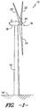
- FIG. 1 illustrates a perspective view of one embodiment of a wind turbine 10.
- the wind turbine 10 generally includes a tower 12 extending from a support surface 14, a nacelle 16 mounted on the tower 12, and a rotor 18 coupled to the nacelle 16.
- the rotor 18 includes a rotatable hub 20 and at least one rotor blade 22 coupled to and extending outwardly from the hub 20.
- the rotor 18 includes three rotor blades 22.
- the rotor 18 may include more or less than three rotor blades 22.
- Each rotor blade 22 may be spaced about the hub 20 to facilitate rotating the rotor 18 to enable kinetic energy to be transferred from the wind into usable mechanical energy, and subsequently, electrical energy.
- the hub 20 may be rotatably coupled to an electric generator (not shown) positioned within the nacelle 16 to permit electrical energy to be produced.
- the rotor blade 22 generally includes a blade root 24 configured for mounting the rotor blade 22 to the hub 20 of the wind turbine 10 ( FIG. 1 ) and a blade tip 26 disposed opposite the blade root 24.
- a body 28 of the rotor blade 22 may generally be configured to extend between the blade root 24 and the blade tip 26 and may serve as the outer casing/skin of the blade 22.
- the body 28 may define a substantially aerodynamic profile, such as by defining a symmetrical or cambered airfoil-shaped cross-section.
- the body 28 may include a pressure side 30 and a suction side 32 extending between a leading edge 34 and a trailing edge 36.
- the rotor blade 22 may have a span 38 defining the total length between the blade root 22 and the blade tip 24 and a chord 40 defining the total length between the leading edge 34 and the trailing edge 36.
- the chord 40 may vary in length with respect to the span 38 as the rotor blade 22 extends from the blade root 22 to the blade tip 24.
- the body 28 of the rotor blade 22 may be formed as a single, unitary component.
- the body 28 may be formed from a plurality of shell components.
- the body 28 may be manufactured from a first shell half generally defining the pressure side 30 of the rotor blade 22 and a second shell half generally defining the suction side 32 of the rotor blade 20, with the shell halves being secured to one another at the leading and trailing edges 34, 36 of the blade 22.
- the body 28 may generally be formed from any suitable material.
- the body 28 may be formed entirely from a laminate composite material, such as a carbon fiber reinforced laminate composite or a glass fiber reinforced laminate composite.
- one or more portions of the body 28 may be configured as a layered construction and may include a core material 42 (e.g., as shown in FIG. 6 ), formed from a lightweight material such as wood (e.g., balsa), foam (e.g., extruded polystyrene foam) or a combination of such materials, disposed between layers of laminate composite material.
- a core material 42 e.g., as shown in FIG. 6
- a lightweight material such as wood (e.g., balsa), foam (e.g., extruded polystyrene foam) or a combination of such materials, disposed between layers of laminate composite material.
- the rotor blade 22 may also include one or more longitudinally extending structural components configured to provide increased stiffness, buckling resistance and/or strength to the rotor blade 22.
- the rotor blade 22 may include a pair of spar caps (e.g., a top spar cap 44 and a bottom spar cap 46) and one or more shear webs 48 extending between the opposed spar caps 44, 46 (e.g., as shown in FIG. 6 ).
- the rotor blade assembly 100 may include a first blade segment 102, a second blade segment 104 and a blade insert 106 configured to be coupled between the first and second blade segments 102, 104.
- the rotor blade assembly 100 may be configured such that, when the first and second blade segments 102, 104 are coupled together via the blade insert 106, a complete rotor blade is formed.
- the first and second blade segments 102, 104 may be formed by dividing a pre-existing rotor blade 22 into two separate blade sections.
- the illustrated rotor blade 22 may be divided into the first and second blade segments 102, 104 by cutting the rotor blade 22 along a joint or cut line 108.
- the first blade segment 102 may correspond to a root segment of the rotor blade 22 and may extend between the blade root 24 and a first joint end 110 formed at the cut line 108.
- the second blade segment 104 may correspond a tip segment of the rotor blade 22 and may extend between the blade tip 26 and a second joint end 112 formed at the cut line 108.
- first blade segment 102 is shown as a root segment and the second blade segment 104 is shown as a tip segment
- first blade segment and second blade segment may generally refer to any suitable segments or sections of the rotor blade 22.
- first blade segment 102 may correspond to a tip segment of the rotor blade 22 and the second blade segment 104 may correspond to a root segment of the rotor blade 22.
- first and second blade segments 102, 104 may correspond to shorter segments of the rotor blade 22.
- first blade segment and second blade segment need not be limited to a single, continuous blade segment.
- first blade segment 102 may be formed from a single, unitary blade segment extending between the blade root 24 and the first joint end 110 or the first blade segment 102 may be formed from two or more blade segments that, when coupled together, extend between blade root 24 and the first joint end 110.
- second blade segment 104 may be formed from a single, unitary blade segment extending between the second joint end 112 and the blade tip 26 or the second blade segment 104 may be formed from two or more blade segments that, when coupled together, extend between the second joint end 112 and the blade tip 26.
- the cut line 108 may generally be located at any suitable position along the span 38 of the rotor blade 22.
- the distance of the cut line 108 from the blade root 24 may range from about 40% to about 95% of the span 38, such as from about 40% to about 80% of the span 28 or from about 50% to about 65% of the span 38.
- the distance of the cut line 108 from the blade root 34 may be less than 40% of the span 38 or greater than 95% of the span 38.
- first and second blade segments 102, 104 need not be formed by cutting or otherwise dividing a pre-existing rotor blade 22 into two separate blade sections.
- first and second blade segments 102, 104 may be separately manufactured and assembled together with the blade insert 106 to form the disclosed rotor blade assembly 100.
- the blade insert 106 of the rotor blade assembly 100 may generally comprise an elongated, aerodynamic body 114 extending between a forward end 116 and an aft end 118, thereby forming a separate blade segment of the rotor blade assembly 100.
- the blade insert 106 may be configured to be coupled between the first and second blade segments 102, 104 in order to form the rotor blade assembly 100.
- the forward end 116 of the blade insert 106 may be configured to be coupled to the joint end 110 of the first blade segment 102 and the aft end 118 of the blade insert 106 may be configured to be coupled to the joint end 112 of the second blade segment 104.
- Suitable configurations and methods for attaching the blade insert 106 between the first and second blade segments 102, 104 will generally be described below with reference to FIGS. 4-16 .
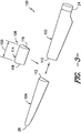
- FIGS. 4-6 one embodiment of a particular blade insert/segment configuration that may be used to effectively and efficiently secure a blade insert 106 between first and second blade segments 102, 104 of a rotor blade assembly 100 is illustrated in accordance with aspects of the present subject matter.
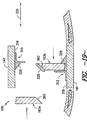
- FIG. 4 illustrates a perspective view of the blade insert 106
- FIG. 5 illustrates a partial, cross-sectional view of the blade insert 106 shown in FIG. 4 taken about line 5-5.
- FIG. 6 illustrates a perspective view of a corresponding configuration that may be used for the first blade segment 102 and/or the second blade segment 104.
- the blade insert 106 may generally include an elongated body 114 extending spanwise between a forward end 116 and an aft end 118, with the forward end 116 configured to be coupled to the joint end 110 of the first blade segment 102 and the aft end 118 being configured to be coupled to the joint end 112 of the second blade segment 104.
- the body 114 may be configured to define a substantially aerodynamic profile, such as by defining a symmetric or cambered airfoil-shaped cross-section.
- the body 114 may include a top side 120 (e.g., a pressure side) and a bottom side 122 (e.g., suction side) extending between a leading edge 124 and a trailing edge 126. Additionally, as shown, the top side 120 of the body 114 may be configured to extend spanwise between a forward edge 128 disposed at the forward end 116 of the blade insert 106) and an aft edge 130 disposed at the aft end 118 of the blade insert 106.
- a top side 120 e.g., a pressure side
- a bottom side 122 e.g., suction side
- the bottom side 122 of the body 114 may be configured to extend spanwise between a forward edge 132 (disposed at the forward end 116 of the blade insert 106 and an aft edge 134 disposed at the aft end 118 of the blade insert 106.
- the blade insert 106 may also include the same or similar internal structural components as the first and second blade segments 102, 104.
- the blade insert 106 may include a pair of longitudinally extending spar caps (e.g., a top spar cap 142 and a bottom spar cap 144), with each spar cap 142, 144 being integrated into and/or forming part of either the top side 120 or the bottom side 122 of the blade insert 106.
- the blade insert 106 may include one or more shear webs 146 ( FIG. 5 ) extending between the opposed spar caps 142, 144.
- a portion of the top side 120 of the blade insert 106 may be recessed or offset from the forward and aft edges 132, 134 of the bottom side 122 of the blade insert 106.
- portions of the top side 120 may be inwardly offset from the forward edge 132 of the bottom side 122 by a first spanwise distance 136 along either side of the top spar cap 142, thereby defining separate offset portions of the forward edge 128 of the top side 120.
- portions of the top side 120 may also be inwardly offset from the aft edge 134 of the bottom side 122 by a second spanwise distance 138 along either side of the top spar cap 142, thereby defining separate offset portions of the aft edge 130 of the top side 120.
- portions of the top side 120 may also be inwardly offset from the aft edge 134 of the bottom side 122 by a second spanwise distance 138 along either side of the top spar cap 142, thereby defining separate offset portions of the aft edge 130 of the top side 120.
- separate access windows 140, 141 may be defined at each end 116, 118 of the blade insert 106 when the insert 106 is positioned between the first and second blade segments 102, 104.
- Such access windows 140, 141 may generally allow for service workers to access the interior of the rotor blade assembly 100, thereby allowing various components to be positioned within the assembly 100 to facilitate securing the blade insert 106 between the blade segments 102, 104.
- a shear web insert 183 may be inserted through one of the access windows 240, 241 and installed horizontally between the blade insert 106 and the blade segment 102 to couple the shear web 48 of the blade segment 102 to the shear web 146 of the blade insert 106.
- first and second spanwise distances 136, 138 may generally correspond to any suitable distance. Additionally, in one embodiment, the first spanwise distance 136 may be equal to the second spanwise distance 138. Alternatively, the first spanwise distance 136 may be greater or less than the second spanwise distance 138.
- the terms "forward” and “aft” are simply used to distinguish the opposed ends 110, 112 and/or edges 128, 130, 132, 134 of the blade insert 106.
- the forward end 110 of the blade insert 106 is described herein as being configured to be coupled to the joint end 110 of the first blade segment 102, the aft end 112 of the blade insert 106 may instead be configured to be coupled to the first blade segment 102.
- the terms “top” and “bottom” are simply used to distinguish the opposed sides 120, 122 of the blade insert 106.
- the top side 120 of the blade insert 106 corresponds to the pressure side while the bottom side 122 corresponds to the suction side.
- the top side 120 of the blade insert 106 may correspond to the suction side while the bottom side 122 may correspond to the pressure side.
- a portion(s) of the top side 120 of the blade insert 106 may also be configured to extend beyond the forward and aft edges 132, 134 of the bottom side 122 of the blade insert 106.
- elongated portions 147 of the top side 120 may extend beyond the forward and aft edges 132, 134 of the bottom side 122, thereby defining extended portions of the forward and aft edges 128, 130 of the top side 120.
- such elongated portions 147 of the top side 120 may be configured to extend to a location at and/or adjacent to the joint ends 110, 112 of the blade segments 102, 104 when the blade insert 106 is positioned between the blade segments 102, 104.
- one or more tapered or scarfed sections may be defined along the top and bottom sides 120, 122 of the blade insert 106.
- first and second top scarfed sections 152, 154 may be defined along the outer surface of the top side 120, with the first top scarfed section 152 extending from an inner edge 156 to the forward edge 128 of the elongated portion 147 of the top side 120 and the second top scarfed section 254 extending from an inner edge 158 to the aft edge 130 of the elongated portion 147 of the top side 120.
- first and second top scarfed sections 152, 154 may be defined along the outer surface of the top side 120, with the first top scarfed section 152 extending from an inner edge 156 to the forward edge 128 of the elongated portion 147 of the top side 120 and the second top scarfed section 254 extending from an inner edge 158 to the aft edge 130 of the elongated portion 147 of the top side 120.
- first and second bottom scarfed sections 160, 162 may be defined along the inner surface of the bottom side 122, with the first bottom scarfed section 160 extending from an inner edge 164 to the forward edge 132 of the bottom side 122 and the second top scarfed section 162 extending from an inner edge (not shown) to the aft edge 134 of the bottom side 122.
- each scarfed section 152, 154, 160, 162 may be configured to taper outwardly from its inner edge 156, 158, 164 (i.e., with the height of each scarfed section 152, 154, 160, 162 increasing from its inner edge 156, 158, 164 to the respective forward or aft edges 128, 130, 132, 134 of the top and bottom sides 120, 122 of the blade insert 106).
- the scarfed sections 152, 154, 160, 162 may generally be defined at any suitable chordwise location along the top and bottom sides 120, 122 of the blade insert 106.
- the scarfed sections 152, 154, 160, 162 may be aligned with the spar caps 142, 144 of the blade insert 106.
- the top scarfed sections 152, 154 are generally aligned with the top spar cap 142 while the bottom scarfed sections 160, 162 are generally aligned with the bottom spar cap 144.
- a width 168 FIG.
- each scarfed section 152, 154, 160, 162 may generally correspond to the width of the spar caps 142, 144.
- the width 168 of each scarfed section 152, 154, 160, 162 may be greater or less than the width of the spar caps 142, 144.
- a portion of the shell(s) forming the blade insert 106 may be recessed relative to the forward and aft edges 128, 130, 132, 134 of the top and bottom sides 120, 122.
- only an inner layer of the top side shell e.g., one or more layers of laminate composite
- only an outer layer of the bottom side shell e.g., one or more layers of laminate composite
- top and bottom flanges 172, 174 may facilitate securing the blade insert 106 between the first and second blade segments 102, 104.
- the outer layers of the shell(s) e.g., one or more outer layers of laminate composite and/or one or more layers of core material 42
- FIG. 6 a perspective view of a suitable segment configuration for attaching each blade segment 102, 104 to the blade insert 106 shown in FIGS. 4 and 5 is illustrated in accordance with aspects of the present subject matter.
- FIG. 6 illustrates a perspective view of the joint end 110 of the first blade segment 102.
- the joint end 112 of the second blade segment 104 may be configured the same as or similar to the joint end 110 shown in FIG. 6 .
- the blade segment 102 may be modified to include scarfed sections 175, 176 configured to be aligned with the scarfed sections 152, 160 of the blade insert 106.
- the blade segment 102 includes a top scarfed section 175 defined along the outer surface of its pressure side 30 that is configured to be aligned with top scarfed section 152 defined at the forward edge 128 of the top side 120 of the blade insert 106.
- the blade segment 102 includes a bottom scarfed section 176 defined along the inner surface of its suction side 32 that is configured to be aligned with the bottom scarfed section 160 defined at the forward edge 132 of the bottom side 122 of the blade insert 106.
- a scarfed connector(s) may be positioned across each aligned pair of scarfed sections 152, 160, 175, 176 to provide a means for securing the blade segment 102 to the blade insert 106.
- the blade segment 102 may include an offset edge(s) 177 at its joint end 110 that is offset from the edge(s) of the opposing side of the blade segment 102 by a given spanwise distance 178.
- a portion of the shell forming the pressure side 30 may be removed between the joint end 110 of the blade segment 102 and a front edge of the top scarfed section 175, thereby defining the offset edge 177.
- this removed portion of the shell may form part of the access window(s) 140, 141 defined between the blade segment 102 and the blade insert 106 when such components are positioned adjacent to one another.
- a portion of the shell(s) forming the pressure and suction sides 30, 32 of the blade segment 102 may be recessed relative to the joint end 110 of the blade segment 102.
- an inner layer of the shell(s) e.g., one or more layers of laminate composite
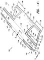
- FIGS. 7-9 several assembly views of the blade insert 106 shown in FIGS. 4 and 5 and the blade segment 102 shown in FIG. 6 are illustrated in accordance with aspects of the present subject matter.
- FIG. 7 illustrates a perspective view of the blade insert 106 and the blade segment 102 positioned end-to-end, with suitable components for securing the blade insert 106 to the blade segment 102 being exploded outward.
- FIG. 8 illustrates a perspective, assembled view of the various components shown in FIG. 7
- FIG. 9 illustrates a cross-sectional view of the assembly shown in FIG. 8 taken about line 9-9.
- access windows e.g., a first access window 140 and a second access window 141
- Such access windows 140, 141 may generally allow a service worker(s) to access the interior of the rotor blade assembly 100, thereby facilitating the installation of many of the assembly components shown in FIG. 7 .
- a bottom scarfed connector 181, bottom shell inserts 182 and a shear web insert 183 may be installed within the rotor blade assembly 100 via the access provided by the access windows 140, 141.
- the access windows 140, 141 may be covered by suitable window covers 184a, 184b to allow the assembly process to be finalized.
- the bottom scarfed section 160 at the forward end 116 of the blade insert 106 may be configured to be aligned with the bottom scarfed section 176 of the blade segment 102.
- the aligned bottom scarfed sections 160, 176 may be configured to abut one another when the blade insert 106 and blade segment 102 are positioned together.
- a bottom scarfed connector 181 may be positioned across the bottom scarfed sections 160, 176 in order to facilitate coupling the blade insert 106 to the blade segment 102.
- the bottom scarfed connector 181 may generally define a tapered profile corresponding to the tapered profiles defined by the bottom scarfed sections 160, 176.
- the bottom scarfed connector 181 may be configured to extend across the interface defined between the blade segment 102 and the blade insert 106 so as to fill the open area defined by the bottom scarfed sections 160, 176.
- the bottom scarfed connector 181 may comprise a pre-fabricated component configured to be separately installed within the rotor blade assembly 100 (via one of the access windows 140, 141) and secured across the aligned bottom scarfed sections 160, 176, such as by securing the scarfed connector 181 within the bottom scarfed sections 160, 176 using suitable adhesives and/or mechanical fasteners (e.g., bolts, screws, pins, rivets, brackets and/or the like).
- suitable adhesives and/or mechanical fasteners e.g., bolts, screws, pins, rivets, brackets and/or the like.
- the bottom scarfed connector 181 may be formed or otherwise built-up within the aligned bottom scarfed sections 160, 176.
- the scarfed connector 181 may be formed using a wet lay-up process, wherein a plurality of plies (including a reinforcement material such as glass or carbon fibers) are positioned across and/or within the bottom scarfed sections 160, 176 and a resin or other suitable matrix material is rolled over or otherwise applied to the surface of the plies and allowed to cure.
- a plurality of plies including a reinforcement material such as glass or carbon fibers
- a resin or other suitable matrix material is rolled over or otherwise applied to the surface of the plies and allowed to cure.
- the bottom flanges 174, 180 of the blade insert 106 and the blade segment 102 may also be configured to abut one another when the blade insert 106 is positioned end-to-end with the blade segment 102.
- suitable bottom shell inserts 182 may be secured across the bottom flanges 174, 180 along either side of the bottom scarfed connector 181 to further secure the blade insert 106 and the blade segment 102 to one another
- the bottom shell inserts 182 may generally configured to extend across the interface defined between the blade segment 102 and the blade insert 106 so as to fill the open area defined by bottom flanges 174, 180. For example, as shown in FIG.
- the bottom shell inserts 182 may generally define a profile matching the profile of the corresponding portions of the shells for the blade insert 106 and the blade segment 102 and may also be formed from the same material (e.g., one or more layers of laminate component and/or one or more layers of core material 44). It should be appreciated that, similar to the bottom scarfed connector 181, the bottom shell inserts 182 may be pre-fabricated components or may be formed or otherwise built-up within the open area defined by the bottom flanges 174, 180.
- a shear web insert 183 may also be installed within the rotor blade assembly 100 via one of the access windows 140, 141.
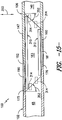
- the shear web insert 183 may generally include a first side face 302 and a second side face 304 extending between first and second ends 306, 308.
- the shear web insert 183 may be configured to extend spanwise between the terminating ends of the shear webs 48, 146 for the blade segment 102 and the blade insert 106. Specifically, as shown in FIG.
- the shear web insert 183 may be configured to a define a length 185 between its first and second ends 306, 308 generally corresponding to the gap defined between the end of the shear web 48 for the blade segment 102 and the end of the shear web 146 for the blade insert 106.
- the shear web insert 183 may be inserted within the rotor blade assembly 100 via one of the access windows 140, 141 and subsequently secured between the shear webs 48, 146.
- one or more positioning devices 310, 312, 314 and/or one or more retention devices may be coupled along the inner surfaces of the rotor blade assembly 100 (e.g., the inner surface 316 ( FIG. 11 ) defined along the pressure side of the assembly 100 and the inner surface 318 ( FIG. 11 ) defined along the suction side of the assembly 100) to assist in installing the shear web insert 183 between the shear webs 48, 146.
- suitable window covers 184a, 184b may then installed between the blade insert 106 and the blade segment 106 so as to cover at least a portion of each access window 140, 141.
- a first window cover 184a may be configured to extend across and/or cover at least a portion of the first access window 140.
- a second window cover 184b may be configured to extend across and/or cover at least a portion of the second access window 141.
- the window covers 184a, 184b may generally have a similar construction to that of the shells used to form the blade insert 106 and the blade segment 102.
- the window covers 184a, 184b may be formed from a layered construction, including one or more layers laminate material and one or more layers of core material 42.
- a portion of the shell(s) forming the window covers 184a, 184b may be recessed or offset, thereby defining cover flanges 188 around the edges of the window covers 184a, 184b.
- the cover flanges 188 may be configured to abut against the top flanges 172, 179 of the blade insert 106 and the blade segment 102.
- a suitable top shell insert 189 may be secured across each interface defined between the blade segment 212 and the window covers 184a, 184b and across each interface defined between the blade insert 106 and the window covers 184a, 184b so as to fill the open area defined by the top and cover flanges 172, 179, 188.
- the top shell inserts 189 may generally define a profile matching the profile of the corresponding portions of the shells for the blade insert 106 and the blade segment 212 and may also be formed from the same material (e.g., one or more layers of laminate component and/or one or more layers of core material 42).
- the rotor blade assembly 100 may also include a top scarfed connector 190 configured to be positioned across the aligned top scarfed sections 152, 175 of the blade insert 106 and the blade segment 102.
- the top scarfed connector 190 may define a tapered profile corresponding to the tapered profiles defined by the top scarfed sections 151, 175.
- the top scarfed connector 190 may be configured to extend across the interface defined between the blade segment 102 and the blade insert 106 so as to fill the area defined by the aligned top scarfed sections 152,175.
- the top scarfed connector 190 and the tip shell inserts 189 may be pre-fabricated components or may be formed or otherwise built-up during assembly of the rotor blade assembly 100.
- an overlaminate may be applied around the outer surface of the assembly 100 to ensure a smooth aerodynamic transition between the blade segment 102 and the blade insert 106.
- the overlaminate may be applied using a wet lay-up process, wherein one or more plies (including a reinforcement material such as glass or carbon fibers) are positioned along the outer surface and a resin or other suitable matrix material is rolled over or otherwise applied to the surface of the plies to form a smooth profile.
- blade insert 106 was described with reference to FIGS. 7-9 as simply being secured to one of the blade segments (e.g., the first blade segment 102), the same or a similar methodology, as well as the same or similar components, may be used to secure the blade insert 106 to the other blade segment (e.g., the second blade segment 104).
- a bottom scarfed connector 181, bottom shell inserts 182, a shear web insert 183, window cover(s) 184a, 184b, top shell inserts 189 and a top scarfed connector 190 may be installed between the aft end 118 of the blade insert 106 and the joint end 112 of the second blade segment 104 to allow such components to be secured to another in the same manner that the blade insert 106 and the first blade segment 102 were secured together (e.g., as shown in FIGS. 7-9 ).
- the blade insert 106 described herein may be considered as a blade segment.
- the disclosed rotor blade assembly 100 may include one or a plurality of blade inserts 106, with each blade insert forming an individual segment of the rotor blade assembly 100.
- FIG. 10 a flow diagram of one embodiment of a method 200 for installing a shear web insert 183 between the blade insert 106 and one of the blade segments 102, 104 will be described in accordance with aspects of the present subject matter.
- the shear web insert 183 must be installed horizontally. Specifically, the shear web 183 must be inserted through one of the access windows 140, 141 and then inserted horizontally between the shear web 146 for the blade insert 106 and the shear web 48 for the corresponding blade segment 102, 104.
- the method 200 will generally be described herein with reference to installing a shear web insert 183 between the blade insert 106 and the first blade segment 102. However, the same methodology may also be utilized for installing a shear web insert 183 between the blade insert 106 and the second blade segment 102.
- the shear web 48 of the first blade segment 102 will be referred to as a "first shear web 48" and the shear web 146 of the blade insert 106 will be described as a "second shear web 146.”
- method elements in FIG. 10 are shown in a particular order, the elements may generally be performed in any suitable order consistent with the disclosure provided herein.
- the method 200 incudes coupling one or more positioning devices to an inner surface(s) of the rotor blade assembly.
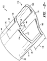
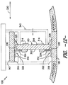
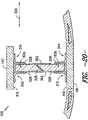
- FIG. 11 illustrates a partially assembled, cross-sectional view of a portion of the disclosed rotor blade assembly 100 having positioning devices 310, 312 installed therein.
- a positioning device(s) 310, 312 may be configured to be coupled along each side of the rotor blade assembly 100.
- a first positioning device 310 may be coupled to the inner surface 316 defined along the pressure side of the rotor blade assembly 100 (e.g., the inner surface 316 defined by the elongated portion 147 of the blade insert 106).
- a second positioning device 312 may be coupled to the inner surface 318 defined along the suction side of the rotor blade assembly 100 (e.g., the inner surface defined by the bottom scarfed connector 191 extending across the interface between the blade insert 106 and the blade segment 102).
- the positioning devices 310, 312 may have any suitable configuration that allows such devices 310, 312 to serve as mechanical stops for positioning the shear web insert 183 between the first and second shear webs 48, 146.
- the positioning devices 310, 312 may each define an "L" shaped structure having a horizontal portion 322 coupled to the inner surface 316, 318 of the assembly 100 (e.g., using a suitable adhesive(s) or mechanical fastener(s)) and a vertical portion 324 extending generally perpendicularly from the horizontal portion 322.
- each positioning device 310, 312 may generally be configured to serve as a mechanical stop for the shear web insert 183 as it is being inserted between the first and second shear webs 48, 146.
- the positioning devices 310, 312 may have any other suitable configuration that allows such devices to function as described herein.
- the first and second positioning devices 310, 312 may generally be configured to be aligned with one another in the horizontal or chordwise direction of the rotor blade assembly 100 (i.e., indicated by arrow 320). Specifically, in several embodiments, the vertical portions 324 of the positioning devices 310, 312 may be aligned at a first chordwise position (indicated by the line 326) that generally corresponds to the location at which the first side face 302 of the shear web insert 183 is to be positioned when the insert 183 is properly installed between the first and second shear webs 48, 146.
- the positioning devices 310, 312 may be configured to extend in the spanwise direction (indicated by arrow 326 in FIG. 9 ) along all or a substantial portion of the length 185 of the shear web insert 183.
- the positioning devices 310, 312 define a length (not shown) generally corresponding to the length 185 of the shear web insert 183.
- the positioning devices 310, 312 may be configured to define a length that is shorter than the overall length 185 of the shear web insert 183.
- a plurality of positioning devices 310, 312 may, for example, be spaced apart along the length 185 of the shear web insert 183.
- the positioning devices 310, 312 may also be used as a means for transferring loads through the rotor blade assembly 100. For example, by coupling one or more positioning devices 310, 312 along the length 185 of the shear web insert 183, shear loads may be transferred between the shear web insert 183 and the body 114 of the blade insert 106 and/or the body 28 of the blade segment 102.
- one or more secondary positioning devices 314 may also be coupled to the shear web insert 183.
- secondary positioning devices 314 may be coupled to the second side face 304 of the shear web insert 183 such that the devices 314 extend outwardly from each end 306, 108 of the insert 183.
- the secondary positioning devices 314 may contact the first and second shear webs 48, 146 when the insert 183 is properly positioned between such shear webs 48, 146 (e.g., as shown in FIG. 16 ).
- the method 200 includes applying an adhesive 328 along the inner surface(s) 316, 318 of the rotor blade assembly 100 at a location adjacent to the positioning device(s) 310, 312.
- a volume of adhesive 328 may be applied in a manner so that the adhesive 328 that extends from the vertical portions 324 of the positioning devices 310, 412 outward along the inner surfaces 316, 318.
- the adhesive 328 may be uniformly spread between the shear web insert 183 and the positioning devices 310, 312 and between the shear web insert 183 and the inner surfaces 316, 318 of the rotor blade assembly 100.
- any suitable adhesive 328 known in the art may be utilized for securing the shear web insert 183 between the first and second shear webs 48, 146.
- the adhesive 328 may be applied along the inner surfaces 316, 318 of the rotor blade assembly 100 so as to form any suitable cross-sectional shape.
- the adhesive 328 forms a triangular cross-sectional shape, which may be advantageous for ensuring proper squeeze out of the adhesive 328.
- the adhesive 328 may be applied to the inner surfaces 316, 318 so as to form any other cross-sectional shape.
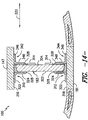
- the method 200 includes inserting the shear web insert 183 horizontally between the first and second shear webs 48, 146.
- the shear web insert 183 may be inserted between the first and second shear webs 48, 146 until the first side face 320 of the insert 183 engages the positioning devices 310, 312 (and/or until the secondary positioning devices 314 engage the first and second shear webs 48, 146), thereby indicating that the shear web insert 183 is properly positioned within the rotor blade assembly 100.
- the shear web insert 183 may be engaged with the positioning devices 310, 312 by contacting the devices 310, 312 directly or by contacting the devices 310, 312 indirectly (e.g., via the adhesive 328).
- the shear web insert 183 may be considered to be engaged with the positioning devices 310 312 even through a layer of adhesive 328 is present between the first side face 302 of the shear web insert 183 and the vertical portion 324 of each positioning device 310, 312.
- a top face 330 and/or a bottom face 332 of the shear web insert 182 may be shaped or otherwise configured to assist in allowing a proper squeeze out of the adhesive 183.
- the top and bottom faces 330, 332 may be angled relative to the inner surfaces 316, 318 of the rotor blade assembly 100.
- the top and bottom faces 330, 332 may be angled towards the positioning devices 310, 312 so that a first gap 334 defined between the top and bottom faces 330, 332 and the inner surfaces 316, 318 at the first side face 302 of the shear web insert 183 is larger than a second gap 336 defined between the top and bottom faces 330, 332 and the inner surfaces 316, 318 at the second side face 304 of the shear web insert 183.
- the top and bottom faces 330, 332 may be configured to define an angle 338 relative to the inner surfaces 316, 318 that ranges from about 5 degrees to about 50 degrees, such as from about 10 degrees to about 45 degrees or from about 10 degrees to about 25 degrees and any other subranges therebetween.
- the adhesive 328 may advantageously spread between the shear web insert 183 and the inner surfaces/positioning devices 316, 318, 310, 312 when the shear web insert 182 is properly positioned between the first and second shear webs 48, 146.
- the gaps 334, 336 defined between the shear web insert 183 and the inner surfaces 316, 318 may generally correspond to any suitable distance.
- the first gap 334 may generally range from about 5 millimeters (mm) to about 50 mm, such as from about 10 mm to about 40 mm or from about 10 mm to about 30 mm and any other subranges therebetween.
- the second gap 336 may generally range from 0 mm to about 30 mm, such as from 0 mm to about 25 mm or from about 5 mm to about 20 mm and any other subranges therebetween.
- the insert 183 may be clamped or otherwise secured within the rotor blade assembly 100 to allow the adhesive 328 to cure.
- a clamp 340 (shown in dashed lines) may be used to clamp the shear web insert 183 to the positioning devices 310, 312 in order to hold the insert 183 in position while the adhesive 328 cures.
- the method 200 includes coupling one or more retention devices 342, 344 to the inner surface(s) 316, 318 of the rotor blade assembly 100 so that the retention devices 342, 344 are positioned adjacent to and/or otherwise engage the second side face 304 of the shear web insert 183.
- a first retention device 342 may be coupled to the inner surface 316 defined along the pressure side of the rotor blade assembly 100.
- a second retention device 344 may be coupled to the inner surface 318 defined along the suction side of the rotor blade assembly 100, with the second retention device 344 being generally aligned with the first retention device 342 in the chordwise direction 320.
- the retention devices 342, 344 may generally be configured to serve as means for retaining the shear web insert 183 within the rotor blade assembly 100. In addition, the retention devices 342, 344 may also be configured to serve as a means for transferring loads between the shear web insert 183 and the body 28, 114 of the rotor blade assembly 102 and/or the blade insert 106.
- the retention devices 342, 344 may generally have any suitable configuration that allows such device(s) 342, 344 to function as described herein.
- the retention devices 342, 344 may be configured similarly to the positioning devices 310, 312 described above and, thus, may include a horizontal portion 346 configured to be coupled to the inner surfaces 316, 318 (e.g., using a suitable adhesive(s) or mechanical fastener(s)) and a vertical portion 348 extending generally perpendicularly from the horizontal portion 346 so as to define a generally "L" shaped structure.
- the retention devices 342, 344 may have any other suitable configuration.
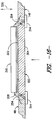
- perpendicularly oriented interfaces may be defined between the ends 306, 308 of the shear web insert 183 and the corresponding ends of the first and second shear webs 48, 146.
- the ends of the insert 183 and the shear webs 48, 146 extend perpendicularly from the inner surfaces 316, 318 of the rotor assembly 100 in a flap wise direction (indicated by arrow 350), thereby defining perpendicular interfaces between the insert 183 and the shear webs 48, 146 in such direction 350.
- angled interfaces may be defined between the shear web insert 183 and the first and second shear webs 48, 146.
- each angled interface may generally define any suitable angle 352, such as an angle 352 ranging from 0 degrees to about 50 degrees or from about 5 degrees to about 50 degrees or from about 10 degrees to about 45 degrees and any other subranges therebetween.
- an angled interface may also be defined between the shear web insert 183 and each shear web 48, 146 in the horizontal or chordwise direction 320.
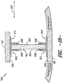
- FIG. 16 illustrates a cross-sectional view of the rotor blade assembly 100 shown in FIG. 9 taken about line 16-16.
- the ends of the insert 183 and the shear webs 48, 146 are angled relative to the chordwise direction 320 such that an angled interface is defined between the insert 183 and each shear web 48, 146.
- the angled interfaces may serve as a positioning or wedging feature when the shear web insert 183 is installed horizontally between the first and second shear webs 48, 146.
- each angled interface may generally define any suitable angle 354, such as an angle 354 ranging from 0 degrees to about 50 degrees or from about 5 degrees to about 50 degrees or from about 10 degrees to about 45 degrees and any other subranges therebetween.
- method element (202) may be performed by coupling the positioning devices 310, 312 to the inner surfaces 316, 318 so that the devices 310, 312 engage opposite faces 302, 304 of the shear web insert 183 (as opposed to coupling the positioning devices 310, 312 along a common face of the shear web insert 183 as shown in FIG. 11 ).
- FIGS. 17 and 18 An example of such an embodiment is illustrated in FIGS. 17 and 18 . As shown in FIG.
- the first positioning device 310 may be coupled to the inner surface 316 at a location for engaging the second side face 304 of the shear web insert 183 and the second positioning device 312 may be coupled to the inner surface 318 at a location for engaging the first side face 302 of the shear web insert 183.
- a suitable adhesive 328 may be applied to the inner surfaces 316, 318 adjacent to each positioning device 310, 312.
- the shear web insert 182 when the shear web insert 182 is inserted through the access window 104, 141 and positioned horizontally between the shear webs 48, 146, the shear web insert 183 may be rotated (as indicated by the dashed lines) until the second side face 304 engages the first positioning device 310 and the first side face 302 engages the second positioning device 312.
- the retention devices 342, 344 may then be coupled to the inner surfaces 316, 318.
- the first retention device 342 may be coupled to the inner surface 316 adjacent to the first side face 302 and the second retention device 344 may be coupled to the inner surface 318 adjacent to the second side face 304.
- shear web insert 183 may be formed from multiple shear web segments coupled to one another within the rotor blade assembly 100. Specifically, embodiments including a multi-piece shear web insert 183 may be advantageous when sufficient access to the interior of the rotor blade assembly 100 is not available via the access windows 140, 141.
- FIGS. 19 and 20 illustrate example installation views of one embodiment of a shear web insert 183 formed from two shear web segments (i.e., an upper shear web segment 183a and a lower shear web segment 183b).
- one of the shear web segments e.g., the lower shear web segment 183b
- a suitable adhesive 328 may be applied along the surface of the installed shear web segment (e.g., angled surface 360) at the location at which the interface between the two shear web segments 183a, 183b will be defined.
- the other shear web segment (e.g., the upper shear web segment 183a) may then be installed within the rotor blade assembly 100, such as by inserting the upper shear web segment 183a horizontally within the assembly 100 until it engages a corresponding positioning device 310 and/or the lower shear web insert 183b.
- suitable retaining devices 342, 344 may also be installed along the shear web segments 183a, 183b opposite the positioning devices 310, 312.
- an overlaminate 362 ( FIG. 20 ) may be applied along each side of the interface defined between the shear web segments 183a, 183b to further secure the connection joint.
- FIGS. 21 and 22 illustrate example installation views of one embodiment of a shear web insert formed from three shear web segments (i.e., an upper shear web segment 183a, a lower shear web segment 183b and a middle shear web segment183c).
- the upper and lower shear web segments 183a, 183b may be initially installed within the rotor blade assembly 100, such as by inserting the upper and lower segments 183a, 183b horizontally within the assembly 100 until each segment 183a, 183b engages its corresponding positioning device 310, 312.
- Suitable retaining devices 342, 344 may also be installed along the upper and lower shear web segments 183a, 183b opposite the positioning devices 310, 312.
- an adhesive 328 may be applied along the surfaces of the installed shear web segments 183a, 183b (e.g., angled surfaces 360) at the locations at which the interfaces between the middle shear web segment 183c and the upper and lower shear web segments 183a, 183b will be defined.
- the middle shear web segment 183c may then be installed horizontally between the upper and lower shear web segments 183a, 183b. As shown in FIG.
- one or more secondary positioning devices 314 may be coupled to the middle shear web segment 183c to ensure that the segment 183c is properly installed between the upper and lower segments 183a, 183b (e.g., by moving the middle shear web segment 183c horizontally until the positioning devices 314 contact the upper and lower shear web segments 183a, 183b. Thereafter, the secondary positioning devices 314 may be removed and an overlaminate 362 may be applied along each side of the interfaces defined between the shear web segments 183a, 183b, 183c to further secure the connection joints. of the claims.
Claims (15)
- Procédé (200) pour installer un insert d'âme de cisaillement (183) entre un segment de pale (212) et un insert de pale d'un ensemble de pales de rotor (100), le segment de pale (212) comprenant une première âme de cisaillement et l'insert de pale comprenant une seconde âme de cisaillement, le procédé comprenant les étapes consistant à :coupler (202) un premier dispositif de positionnement (310) le long d'une surface interne d'un premier côté d'un ensemble de pales de rotor (100) ;insérer (206) le premier insert âme de cisaillement (183) horizontalement entre la première et la seconde âme de cisaillement jusqu'à ce qu'une première face latérale de l'insert d'âme de cisaillement s'engage sur le premier dispositif de positionnement ; etcoupler (208) un premier dispositif de rétention (342) le long de la surface interne du premier côté de l'ensemble de pales de rotor (100) de sorte que le premier dispositif de rétention (342) soit adjacent à une seconde face latérale de l'insert d'âme de cisaillement (183), la seconde face latérale étant en regard de la première face latérale.
- Procédé (200) selon la revendication 1, comprenant en outre le couplage d'un second dispositif de positionnement (312) le long d'une surface interne d'un second côté de l'ensemble de pales de rotor (100), le second dispositif de positionnement (312) étant généralement aligné avec le premier dispositif de positionnement dans le sens de la corde de l'ensemble de pales de rotor.
- Procédé (200) selon la revendication 2, dans lequel l'insert d'âme de cisaillement (183) est inséré horizontalement entre la première et la seconde âme de cisaillement jusqu'à ce que la première face latérale de l'insert d'âme de cisaillement s'engage sur le premier et le second dispositif de positionnement (310, 312).
- Procédé (200) selon l'une quelconque des revendications précédentes, comprenant en outre le couplage d'un second dispositif de rétention (344) le long de la surface interne du second côté de l'ensemble de pales de rotor (100) de sorte que le second dispositif de rétention (344) soit adjacent à la seconde face latérale de l'insert d'âme de cisaillement (183), le second dispositif de rétention (344) étant généralement aligné avec le premier dispositif de rétention (342) dans le sens de la corde.
- Procédé (200) selon l'une quelconque des revendications précédentes, comprenant en outre l'insertion de l'insert d'âme de cisaillement (183) horizontalement entre la première et la seconde âme de cisaillement de sorte qu'un premier intervalle (334) soit défini entre la surface interne et une face supérieure (330) de l'insert d'âme de cisaillement le long de la première face latérale de l'insert d'âme de cisaillement et qu'un second intervalle (336) soit défini entre la surface interne et la face supérieure le long de la seconde face latérale de l'insert d'âme de cisaillement.
- Procédé (200) selon la revendication 5, dans lequel la face supérieure (330) est oblique de sorte que le premier intervalle (334) soit plus grand que le second intervalle (336).
- Procédé (200) selon la revendication 5 ou la revendication 6, dans lequel la face supérieure (330) est orientée selon un angle allant d'environ 5 degrés à environ 50 degrés.
- Procédé (200) selon l'une quelconque des revendications 5 à 7, dans lequel le premier intervalle (334) se situe dans une plage d'environ 5 millimètres à environ 50 millimètres et le second intervalle (336) dans un intervalle de 0 millimètre à environ 30 millimètres.
- Procédé (200) selon l'une quelconque des revendications précédentes, comprenant en outre l'application d'un adhésif (328) le long de la surface interne à un emplacement adjacent au premier dispositif de positionnement (310) avant d'insérer l'insert d'âme de cisaillement (183) entre la première et la seconde âme de cisaillement.
- Procédé (200) selon l'une quelconque des revendications précédentes, dans lequel une fenêtre d'accès est définie entre le segment de pale et l'insert de pale, comprenant en outre l'insertion de l'insert d'âme de cisaillement à travers la fenêtre d'accès avant d'insérer l'insert d'âme de cisaillement (183) horizontalement entre la première et la seconde âme de cisaillement.
- Procédé (200) selon l'une quelconque des revendications précédentes, dans lequel une interface oblique est définie entre l'insert d'âme de cisaillement (183) et au moins l'une de la première âme de cisaillement ou de la seconde âme de cisaillement, l'interface oblique étant inclinée par rapport au sens de la corde de l'ensemble de pales de rotor.
- Procédé (200) selon l'une quelconque des revendications précédentes, dans lequel une interface oblique est définie entre l'insert d'âme de cisaillement (183) et au moins l'une de la première âme de cisaillement ou de la seconde âme de cisaillement, l'interface oblique étant inclinée par rapport au sens de battement de l'ensemble de pales de rotor.
- Procédé (200) selon l'une quelconque des revendications précédentes, comprenant en outre le couplage d'un dispositif de positionnement secondaire avec la seconde face latérale de sorte que le dispositif de positionnement secondaire soit configuré pour venir en contact avec l'une de la première âme de cisaillement ou de la seconde âme de cisaillement lorsque l'insert d'âme de cisaillement est inséré entre la première et la seconde âme de cisaillement.
- Procédé (200) selon l'une quelconque des revendications précédentes, comprenant en outre le couplage d'un second dispositif de positionnement le long d'une surface interne d'un second côté de l'ensemble de pales de rotor, dans lequel l'insertion de l'insert d'âme de cisaillement horizontalement entre la première et la seconde âme de cisaillement comprend la rotation de l'insert d'âme de cisaillement entre la première et la seconde âme de cisaillement jusqu'à ce que l'insert d'âme de cisaillement s'engage dans le premier et le second dispositif de positionnement (310, 312).
- Ensemble de pales de rotor (100) pour une éolienne, l'ensemble de pales de rotor comprenant :un segment de pale définissant une extrémité de jonction, le segment de pale comprenant une première âme de cisaillement ;un insert de pale couplé à l'extrémité de jonction du segment de pale, l'insert de pale comprenant une seconde âme de cisaillement ;un insert d'âme de cisaillement (183) s'étendant entre la première et la seconde âme de cisaillement, l'insert d'âme de cisaillement définissant une première face latérale et une seconde face latérale disposée en regard de la première face latérale ;un premier dispositif de positionnement (310) couplé à une surface interne d'au moins l'un du segment de pale ou de l'insert de pale le long d'un premier côté de l'ensemble de pales de rotor (100), le premier dispositif de positionnement étant configuré pour s'engager sur la première face latérale de l'insert d'âme de cisaillement (183) ; etun premier dispositif de retenue (342) couplé à la surface interne le long du premier côté de l'ensemble de pales de rotor (100), le premier dispositif de retenue (342) étant adjacent à la seconde face latérale de l'insert d'âme de cisaillement (183).
Applications Claiming Priority (1)
| Application Number | Priority Date | Filing Date | Title |
|---|---|---|---|
| US14/012,192 US9506452B2 (en) | 2013-08-28 | 2013-08-28 | Method for installing a shear web insert within a segmented rotor blade assembly |
Publications (2)
| Publication Number | Publication Date |
|---|---|
| EP2843227A1 EP2843227A1 (fr) | 2015-03-04 |
| EP2843227B1 true EP2843227B1 (fr) | 2016-06-15 |
Family
ID=51357732
Family Applications (1)
| Application Number | Title | Priority Date | Filing Date |
|---|---|---|---|
| EP14180650.5A Active EP2843227B1 (fr) | 2013-08-28 | 2014-08-12 | Procédé d'installation d'un insert âme de cisaillement au sein d'un ensemble de lame de rotor segmenté |
Country Status (3)
| Country | Link |
|---|---|
| US (1) | US9506452B2 (fr) |
| EP (1) | EP2843227B1 (fr) |
| ES (1) | ES2583406T3 (fr) |
Cited By (1)
| Publication number | Priority date | Publication date | Assignee | Title |
|---|---|---|---|---|
| CN111094740A (zh) * | 2017-08-17 | 2020-05-01 | 通用电气公司 | 未对准翼梁帽的嵌接接头连接 |
Families Citing this family (19)
| Publication number | Priority date | Publication date | Assignee | Title |
|---|---|---|---|---|
| US20150152838A1 (en) * | 2013-12-02 | 2015-06-04 | General Electric Company | Spar caps-shear web assembly configuration for wind turbine blades, and methods thereof |
| US20150167473A1 (en) * | 2013-12-17 | 2015-06-18 | General Electric Company | Modified rotor blade assemblies with access windows and methods for making the same |
| ES2872401T3 (es) * | 2014-03-10 | 2021-11-02 | Siemens Gamesa Renewable Energy As | Un método para fabricar una pala de rotor para una turbina eólica |
| GB2527587A (en) | 2014-06-27 | 2015-12-30 | Vestas Wind Sys As | Improvements relating to wind turbine blade manufacture |
| GB2529186A (en) * | 2014-08-12 | 2016-02-17 | Vestas Wind Sys As | Improvements relating to wind turbine blade manufacture |
| DK3165762T3 (da) * | 2015-11-06 | 2024-03-04 | Nordex Energy Spain S A | Vindmølle-rotorblad |
| US10519927B2 (en) * | 2017-02-20 | 2019-12-31 | General Electric Company | Shear web for a wind turbine rotor blade |
| US10828843B2 (en) | 2017-03-16 | 2020-11-10 | General Electric Company | Shear webs for wind turbine rotor blades and methods for manufacturing same |
| CN108626076A (zh) * | 2017-03-21 | 2018-10-09 | 中材科技风电叶片股份有限公司 | 叶根挡板与叶根的连接结构 |
| US10502181B2 (en) * | 2017-06-22 | 2019-12-10 | General Electric Company | Bonded window cover with joint assembly for a wind turbine rotor blade |
| US10544776B2 (en) | 2017-07-27 | 2020-01-28 | General Electric Company | Injection method and device for connecting and repairing a shear web |
| CN107559156A (zh) * | 2017-10-26 | 2018-01-09 | 中材科技风电叶片股份有限公司 | 叶根挡板以及风电叶片 |
| CN112469894B (zh) * | 2018-06-01 | 2023-08-22 | 维斯塔斯风力系统有限公司 | 模块化风力涡轮机叶片 |
| EP3890954B1 (fr) * | 2018-12-03 | 2023-11-01 | Vestas Wind Systems A/S | Améliorations apportées à la fabrication dune pale d'éolienne |
| WO2020119870A1 (fr) * | 2018-12-10 | 2020-06-18 | Vestas Wind Systems A/S | Améliorations apportées à la fabrication de pales d'éolienne |
| EP3808972A1 (fr) | 2019-10-18 | 2021-04-21 | VENSYS Energy AG | Raccordement entre les segments longitudinaux d'une pale de rotor du rotor d'une éolienne |
| EP3974643A1 (fr) * | 2020-09-25 | 2022-03-30 | Siemens Gamesa Renewable Energy Innovation & Technology S.L. | Pale de rotor d'une éolienne et éolienne |
| CN116547128A (zh) * | 2020-11-12 | 2023-08-04 | 维斯塔斯风力系统有限公司 | 在抗剪腹板与壳体之间具有改进的粘接接头的风力涡轮机叶片 |
| CN112848350B (zh) * | 2021-03-23 | 2023-01-03 | 国电联合动力技术(保定)有限公司 | 一种叶片腹板避雷导线的定位装置 |
Family Cites Families (103)
| Publication number | Priority date | Publication date | Assignee | Title |
|---|---|---|---|---|
| US2312219A (en) | 1941-04-21 | 1943-02-23 | Sensenich Brothers | Aircraft propeller |
| US4295790A (en) * | 1979-06-21 | 1981-10-20 | The Budd Company | Blade structure for use in a windmill |
| US4474536A (en) | 1980-04-09 | 1984-10-02 | Gougeon Brothers, Inc. | Wind turbine blade joint assembly and method of making wind turbine blades |
| DE3113079C2 (de) | 1981-04-01 | 1985-11-21 | Messerschmitt-Bölkow-Blohm GmbH, 8000 München | Aerodynamischer Groß-Flügel und Verfahren zu dessen Herstellung |
| US4671470A (en) * | 1985-07-15 | 1987-06-09 | Beech Aircraft Corporation | Method for fastening aircraft frame elements to sandwich skin panels covering same using woven fiber connectors |
| US5088665A (en) | 1989-10-31 | 1992-02-18 | The United States Of America As Represented By The Administrator Of The National Aeronautics And Space Administration | Serrated trailing edges for improving lift and drag characteristics of lifting surfaces |
| EE200100306A (et) | 1998-12-09 | 2002-08-15 | Wobben Aloys | Tuuleenergiaseadme rootorilaba |
| US6513757B1 (en) * | 1999-07-19 | 2003-02-04 | Fuji Jukogyo Kabushiki Kaisha | Wing of composite material and method of fabricating the same |
| DE19962454A1 (de) | 1999-12-22 | 2001-07-05 | Aerodyn Eng Gmbh | Rotorblatt für Windenergieanlagen |
| DE19962989B4 (de) | 1999-12-24 | 2006-04-13 | Wobben, Aloys, Dipl.-Ing. | Rotorblatt für Windenergieanlagen |
| JP3825346B2 (ja) | 2001-03-27 | 2006-09-27 | 三菱重工業株式会社 | 風力発電装置用複合材ブレード |
| US6726439B2 (en) | 2001-08-22 | 2004-04-27 | Clipper Windpower Technology, Inc. | Retractable rotor blades for power generating wind and ocean current turbines and means for operating below set rotor torque limits |
| JP2003254225A (ja) | 2002-03-05 | 2003-09-10 | Ebara Corp | 風車の気流騒音低減装置 |
| DK175562B1 (da) | 2002-03-19 | 2004-12-06 | Lm Glasfiber As | Vindmöllevinge med kulfibertip |
| DK175275B1 (da) | 2002-03-19 | 2004-08-02 | Lm Glasfiber As | Overgangsområde i vindmöllevinge |
| US6972498B2 (en) | 2002-05-28 | 2005-12-06 | General Electric Company | Variable diameter wind turbine rotor blades |
| US6902370B2 (en) | 2002-06-04 | 2005-06-07 | Energy Unlimited, Inc. | Telescoping wind turbine blade |
| DE10235496B4 (de) | 2002-08-02 | 2015-07-30 | General Electric Co. | Verfahren zum Herstellen eines Rotorblattes, Rotorblatt und Windenergieanlage |
| WO2004076852A2 (fr) | 2003-02-28 | 2004-09-10 | Vestas Wind Systems A/S | Procede de fabrication d'une pale d'eolienne, pale d'eolienne, capot avant et utilisation d'un capot avant |
| ES2270058T3 (es) | 2003-03-06 | 2007-04-01 | Vestas Wind Systems A/S | Conexion entre elementos. |
| EP1603735B1 (fr) | 2003-03-06 | 2007-03-07 | Vestas Wind System A/S | Connexion entre des composites ayant des proprietes non compatibles et procede de preparation |
| DE10336461A1 (de) | 2003-08-05 | 2005-03-03 | Aloys Wobben | Verfahren zur Herstellung eines Rotorblattes einer Windenergieanlage |
| JP2005061320A (ja) | 2003-08-12 | 2005-03-10 | Kunio Miyazaki | 風力発電装置における風車構造 |
| DK1668246T3 (en) | 2003-09-29 | 2015-01-19 | Vestas Wind Sys As | WINDOW LOCK PROTECTION SYSTEM FOR A WIND MILL |
| FR2864175B1 (fr) | 2003-12-22 | 2008-03-28 | Airbus | Eolienne |
| US7581926B1 (en) | 2004-03-22 | 2009-09-01 | Clipper Windpower Technology, Inc. | Servo-controlled extender mechanism for extendable rotor blades for power generating wind and ocean current turbines |
| EP1584817A1 (fr) | 2004-04-07 | 2005-10-12 | Gamesa Eolica, S.A. (Sociedad Unipersonal) | Pale d'éolienne |
| CN1977108B (zh) | 2004-06-30 | 2011-09-14 | 维斯塔斯风力系统有限公司 | 由两个分离的部分制成的风轮机叶片以及装配方法 |
| US8419362B2 (en) | 2004-08-31 | 2013-04-16 | Hamilton Sundstrand Corporation | Foldable blades for wind turbines |
| US7381029B2 (en) | 2004-09-30 | 2008-06-03 | General Electric Company | Multi-piece wind turbine rotor blades and wind turbines incorporating same |
| US7246998B2 (en) | 2004-11-18 | 2007-07-24 | Sikorsky Aircraft Corporation | Mission replaceable rotor blade tip section |
| DK176176B1 (da) | 2004-11-24 | 2006-11-27 | Siemens Wind Power As | Fremgangsmåde og samlestykke til samling af en vinge, fortrinsvis vindmöllevinge, i sektioner |
| CA2593477C (fr) | 2004-12-29 | 2010-02-09 | Vestas Wind Systems A/S | Methode de fabrication pour organe de coque de pale d'eolienne avec organe de fixation et pale d'eolienne a organe de fixation |
| DK176564B1 (da) | 2004-12-29 | 2008-09-01 | Lm Glasfiber As | Fiberforstærket samling |
| US7582977B1 (en) | 2005-02-25 | 2009-09-01 | Clipper Windpower Technology, Inc. | Extendable rotor blades for power generating wind and ocean current turbines within a module mounted atop a main blade |
| ES2265760B1 (es) | 2005-03-31 | 2008-01-16 | GAMESA INNOVATION & TECHNOLOGY, S.L. | Pala para generadores eolicos. |
| US7393488B2 (en) * | 2005-05-25 | 2008-07-01 | The Boeing Company | Methods of joining structures and joints formed thereby |
| DK200500899A (da) | 2005-06-17 | 2006-12-18 | Lm Glasfiber As | Vinge med hængslet vingetip |
| US7637721B2 (en) | 2005-07-29 | 2009-12-29 | General Electric Company | Methods and apparatus for producing wind energy with reduced wind turbine noise |
| US7690895B2 (en) | 2005-07-29 | 2010-04-06 | General Electric Company | Multi-piece passive load reducing blades and wind turbines using same |
| EP1754886B1 (fr) | 2005-08-17 | 2012-10-10 | General Electric Company | Aube de rotor pour éolienne |
| US7458777B2 (en) | 2005-09-22 | 2008-12-02 | General Electric Company | Wind turbine rotor assembly and blade having acoustic flap |
| ES2318925B1 (es) | 2005-09-22 | 2010-02-11 | GAMESA INNOVATION & TECHNOLOGY, S.L. | Aerogenerador con un rotor de palas que reduce el ruido. |
| ES2297998B1 (es) | 2005-10-28 | 2009-07-20 | GAMESA INNOVATION & TECHNOLOGY, S.L. | Pala partida para aerogeneradores. |
| US7393184B2 (en) | 2005-11-10 | 2008-07-01 | General Electric Company | Modular blades and methods for making same |
| US7798780B2 (en) | 2005-12-19 | 2010-09-21 | General Electric Company | Modularly constructed rotorblade and method for construction |
| US7427189B2 (en) | 2006-02-13 | 2008-09-23 | General Electric Company | Wind turbine rotor blade |
| NL1031223C1 (nl) | 2006-02-23 | 2007-08-24 | Stichting Nationaal Lucht En R | Reductie van windturbinegeluid door borstels op de achterrand van de bladen. |
| US7517198B2 (en) | 2006-03-20 | 2009-04-14 | Modular Wind Energy, Inc. | Lightweight composite truss wind turbine blade |
| US20070243387A1 (en) | 2006-04-13 | 2007-10-18 | Lin Wendy W | Dual cure resin composite system and method of manufacturing the same |
| US7654799B2 (en) | 2006-04-30 | 2010-02-02 | General Electric Company | Modular rotor blade for a wind turbine and method for assembling same |
| DE102006022279B4 (de) | 2006-05-11 | 2016-05-12 | Aloys Wobben | Rotorblatt für eine Windenergieanlage |
| US8608441B2 (en) | 2006-06-12 | 2013-12-17 | Energyield Llc | Rotatable blade apparatus with individually adjustable blades |
| BRPI0714341A2 (pt) | 2006-07-21 | 2013-03-12 | Clipper Windpower Tecnology Inc | estrutura de pÁ de rotor retratÍl |
| WO2008108881A2 (fr) | 2006-09-08 | 2008-09-12 | Steven Sullivan | Procédé et dispositif pour atténuer des sillages de tourbillon d'attaque de corps générateurs de levage ou de poussée |
| US7810757B2 (en) * | 2006-11-02 | 2010-10-12 | The Boeing Company | Mounting device for an aircraft |
| US7811063B2 (en) | 2006-11-03 | 2010-10-12 | General Electric Company | Damping element for a wind turbine rotor blade |
| US20080166241A1 (en) | 2007-01-04 | 2008-07-10 | Stefan Herr | Wind turbine blade brush |
| JP5242920B2 (ja) | 2007-01-23 | 2013-07-24 | 株式会社日立製作所 | 風車用分割翼 |
| WO2008089765A2 (fr) * | 2007-01-25 | 2008-07-31 | Danmarks Tekniske Universitet | Pale d'éolienne renforcée |
| US7976282B2 (en) | 2007-01-26 | 2011-07-12 | General Electric Company | Preform spar cap for a wind turbine rotor blade |
| ES2342638B1 (es) | 2007-02-28 | 2011-05-13 | GAMESA INNOVATION & TECHNOLOGY, S.L. | Una pala de aerogenerador multi-panel. |
| WO2008113349A2 (fr) | 2007-03-20 | 2008-09-25 | Vestas Wind Systems A/S | Éolienne à rotation lente dotée de pales plus effilées |
| US20080232966A1 (en) | 2007-03-20 | 2008-09-25 | Wen-Chang Wang | Detachable blade assembly for horizontal-axis wind turbine |
| ES2345583B1 (es) | 2007-05-31 | 2011-07-28 | GAMESA INNOVATION & TECHNOLOGY, S.L. | Pala de aerogenerador con dispositivos anti-ruido. |
| US7927078B2 (en) | 2007-07-12 | 2011-04-19 | General Electric Company | Wind turbine blade tip vortex breakers |
| NL2000821C2 (nl) | 2007-08-17 | 2009-02-18 | Stichting Energie | Windturbine en rotorblad. |
| DE102007041649A1 (de) | 2007-09-03 | 2009-03-05 | Daubner & Stommel GbR Bau-Werk-Planung (vertretungsberechtigter Gesellschafter: Matthias Stommel, 27777 Ganderkesee) | Rotorblatt, Windenergieanlage sowie Verfahren zum Betreiben einer Windenergieanlage |
| ES2337645B1 (es) | 2007-09-14 | 2011-03-11 | GAMESA INNOVATION & TECHNOLOGY, S.L. | Union de pala sensorizada. |
| US8123488B2 (en) | 2007-09-17 | 2012-02-28 | General Electric Company | System and method for joining turbine blades |
| US20090074585A1 (en) | 2007-09-19 | 2009-03-19 | General Electric Company | Wind turbine blades with trailing edge serrations |
| EP2053240B1 (fr) | 2007-10-22 | 2011-03-30 | Actiflow B.V. | Éolienne avec contrôle de couche limite |
| US8221085B2 (en) | 2007-12-13 | 2012-07-17 | General Electric Company | Wind blade joint bonding grid |
| US8171633B2 (en) | 2007-12-19 | 2012-05-08 | General Electric Company | Method for assembling a multi-segment wind turbine blade |
| US7740453B2 (en) * | 2007-12-19 | 2010-06-22 | General Electric Company | Multi-segment wind turbine blade and method for assembling the same |
| US8167569B2 (en) * | 2007-12-21 | 2012-05-01 | General Electric Company | Structure and method for self-aligning rotor blade joints |
| US8231351B2 (en) | 2007-12-27 | 2012-07-31 | General Electric Company | Adaptive rotor blade for a wind turbine |
| US8240962B2 (en) | 2007-12-28 | 2012-08-14 | General Electric Company | Integrated shipping fixture and assembly method for jointed wind turbine blades |
| EP2288807B1 (fr) | 2008-05-07 | 2013-09-18 | Vestas Wind Systems A/S | Aube sectionnelle |
| US7975965B2 (en) | 2008-05-13 | 2011-07-12 | The Boeing Company | Wing tip joint in airfoils |
| EP2138716B2 (fr) | 2008-06-27 | 2024-02-14 | Siemens Gamesa Renewable Energy Innovation & Technology, S.L. | Insert de pale |
| DE102008038620A1 (de) | 2008-06-27 | 2009-12-31 | Powerblades Gmbh | Verfahren und Fertigungsform zur Fertigung eines Rotorblattes für eine Windenergieanlage |
| US8807954B2 (en) * | 2008-08-25 | 2014-08-19 | Vestas Wind Systems A/S | Assembly and method of preparing an assembly |
| US7866951B2 (en) | 2008-08-29 | 2011-01-11 | General Electric Company | Wind turbine blades with cross webs |
| JP5249684B2 (ja) * | 2008-09-04 | 2013-07-31 | 三菱重工業株式会社 | 風車翼 |
| US7891947B2 (en) | 2008-12-12 | 2011-02-22 | General Electric Company | Turbine blade and method of fabricating the same |
| DK2391807T3 (en) | 2009-01-27 | 2015-07-27 | Vestas Wind Sys As | TITLE BY wind turbine blade |
| US7841835B2 (en) * | 2009-02-20 | 2010-11-30 | General Electric Company | Spar cap for wind turbine blades |
| US7854594B2 (en) | 2009-04-28 | 2010-12-21 | General Electric Company | Segmented wind turbine blade |
| US7998303B2 (en) | 2009-05-28 | 2011-08-16 | General Electric Company | Method for assembling jointed wind turbine blade |
| US7927077B2 (en) | 2009-07-09 | 2011-04-19 | General Electric Company | Wind blade spar cap laminate repair |
| GB201011539D0 (en) | 2010-07-08 | 2010-08-25 | Blade Dynamics Ltd | A wind turbine blade |
| US7976275B2 (en) | 2010-08-30 | 2011-07-12 | General Electric Company | Wind turbine rotor blade assembly having an access window and related methods |
| US7922454B1 (en) * | 2010-10-29 | 2011-04-12 | General Electric Company | Joint design for rotor blade segments of a wind turbine |
| US8393871B2 (en) * | 2011-07-19 | 2013-03-12 | General Electric Company | Wind turbine blade shear web connection assembly |
| US8235671B2 (en) | 2011-07-19 | 2012-08-07 | General Electric Company | Wind turbine blade shear web connection assembly |
| US8257048B2 (en) * | 2011-07-19 | 2012-09-04 | General Electric Company | Wind turbine blade multi-component shear web with intermediate connection assembly |
| US8517689B2 (en) | 2011-10-13 | 2013-08-27 | General Electric Company | Multi-segment wind turbine rotor blade with span-wise offset joints |
| IN2012DE00572A (fr) * | 2012-02-29 | 2015-06-05 | Gen Electric | |
| IN2012DE00573A (fr) * | 2012-02-29 | 2015-06-05 | Gen Electric | |
| US8449259B1 (en) * | 2012-05-15 | 2013-05-28 | Modular Wind Energy, Inc. | Lightning protection for wind turbine blades, and associated systems and methods |
| US8973871B2 (en) * | 2013-01-26 | 2015-03-10 | The Boeing Company | Box structures for carrying loads and methods of making the same |
| US9605651B2 (en) * | 2013-12-04 | 2017-03-28 | General Electric Company | Spar assembly for a wind turbine rotor blade |
-
2013
- 2013-08-28 US US14/012,192 patent/US9506452B2/en active Active
-
2014
- 2014-08-12 ES ES14180650.5T patent/ES2583406T3/es active Active
- 2014-08-12 EP EP14180650.5A patent/EP2843227B1/fr active Active
Cited By (1)
| Publication number | Priority date | Publication date | Assignee | Title |
|---|---|---|---|---|
| CN111094740A (zh) * | 2017-08-17 | 2020-05-01 | 通用电气公司 | 未对准翼梁帽的嵌接接头连接 |
Also Published As
| Publication number | Publication date |
|---|---|
| ES2583406T3 (es) | 2016-09-20 |
| US20150064014A1 (en) | 2015-03-05 |
| EP2843227A1 (fr) | 2015-03-04 |
| US9506452B2 (en) | 2016-11-29 |
Similar Documents
| Publication | Publication Date | Title |
|---|---|---|
| EP2843227B1 (fr) | Procédé d'installation d'un insert âme de cisaillement au sein d'un ensemble de lame de rotor segmenté | |
| US9297357B2 (en) | Blade insert for a wind turbine rotor blade | |
| EP2634417B1 (fr) | Insert pour pale de rotor de turbine éolienne | |
| EP2634418B1 (fr) | Insert de lame pour pale de rotor de turbine éolienne et procédés associés | |
| EP3708826B1 (fr) | Système de pointe d'une pale de turbine éolienne | |
| US7922454B1 (en) | Joint design for rotor blade segments of a wind turbine | |
| US10544776B2 (en) | Injection method and device for connecting and repairing a shear web | |
| US20110243736A1 (en) | Joint sleeve for a rotor blade assembly of a wind turbine | |
| US10920743B2 (en) | Misaligned spar cap scarf joint connection | |
| US8622707B2 (en) | Root attachment for a rotor blade assembly | |
| EP3418558B1 (fr) | Couverture de fenêtre liée avec ensemble de joint pour pale de rotor de turbine éolienne | |
| EP2728169A2 (fr) | Éléments structurels pour pale de rotor d'éolienne | |
| US9951751B2 (en) | Segmented wind turbine rotor blade with rod and tube joint connection | |
| CN112912615A (zh) | 具有中空弦向延伸销的风力涡轮接合的转子叶片 | |
| CN112969850A (zh) | 针对利用替换叶梢节段改装而预先分级的风轮机转子叶片 |
Legal Events
| Date | Code | Title | Description |
|---|---|---|---|
| 17P | Request for examination filed |
Effective date: 20140812 |
|
| AK | Designated contracting states |
Kind code of ref document: A1 Designated state(s): AL AT BE BG CH CY CZ DE DK EE ES FI FR GB GR HR HU IE IS IT LI LT LU LV MC MK MT NL NO PL PT RO RS SE SI SK SM TR |
|
| AX | Request for extension of the european patent |
Extension state: BA ME |
|
| PUAI | Public reference made under article 153(3) epc to a published international application that has entered the european phase |
Free format text: ORIGINAL CODE: 0009012 |
|
| R17P | Request for examination filed (corrected) |
Effective date: 20150904 |
|
| RBV | Designated contracting states (corrected) |
Designated state(s): AL AT BE BG CH CY CZ DE DK EE ES FI FR GB GR HR HU IE IS IT LI LT LU LV MC MK MT NL NO PL PT RO RS SE SI SK SM TR |
|
| GRAP | Despatch of communication of intention to grant a patent |
Free format text: ORIGINAL CODE: EPIDOSNIGR1 |
|
| INTG | Intention to grant announced |
Effective date: 20160126 |
|
| GRAS | Grant fee paid |
Free format text: ORIGINAL CODE: EPIDOSNIGR3 |
|
| GRAA | (expected) grant |
Free format text: ORIGINAL CODE: 0009210 |
|
| AK | Designated contracting states |
Kind code of ref document: B1 Designated state(s): AL AT BE BG CH CY CZ DE DK EE ES FI FR GB GR HR HU IE IS IT LI LT LU LV MC MK MT NL NO PL PT RO RS SE SI SK SM TR |
|
| REG | Reference to a national code |
Ref country code: CH Ref legal event code: EP Ref country code: GB Ref legal event code: FG4D |
|
| REG | Reference to a national code |
Ref country code: IE Ref legal event code: FG4D |
|
| REG | Reference to a national code |
Ref country code: AT Ref legal event code: REF Ref document number: 806645 Country of ref document: AT Kind code of ref document: T Effective date: 20160715 |
|
| REG | Reference to a national code |
Ref country code: DE Ref legal event code: R096 Ref document number: 602014002312 Country of ref document: DE |
|
| REG | Reference to a national code |
Ref country code: DK Ref legal event code: T3 Effective date: 20160728 |
|
| REG | Reference to a national code |
Ref country code: ES Ref legal event code: FG2A Ref document number: 2583406 Country of ref document: ES Kind code of ref document: T3 Effective date: 20160920 |
|
| REG | Reference to a national code |
Ref country code: LT Ref legal event code: MG4D |
|
| REG | Reference to a national code |
Ref country code: NL Ref legal event code: MP Effective date: 20160615 |
|
| PG25 | Lapsed in a contracting state [announced via postgrant information from national office to epo] |
Ref country code: FI Free format text: LAPSE BECAUSE OF FAILURE TO SUBMIT A TRANSLATION OF THE DESCRIPTION OR TO PAY THE FEE WITHIN THE PRESCRIBED TIME-LIMIT Effective date: 20160615 Ref country code: NO Free format text: LAPSE BECAUSE OF FAILURE TO SUBMIT A TRANSLATION OF THE DESCRIPTION OR TO PAY THE FEE WITHIN THE PRESCRIBED TIME-LIMIT Effective date: 20160915 Ref country code: LT Free format text: LAPSE BECAUSE OF FAILURE TO SUBMIT A TRANSLATION OF THE DESCRIPTION OR TO PAY THE FEE WITHIN THE PRESCRIBED TIME-LIMIT Effective date: 20160615 |
|
| REG | Reference to a national code |
Ref country code: AT Ref legal event code: MK05 Ref document number: 806645 Country of ref document: AT Kind code of ref document: T Effective date: 20160615 |
|
| PG25 | Lapsed in a contracting state [announced via postgrant information from national office to epo] |
Ref country code: RS Free format text: LAPSE BECAUSE OF FAILURE TO SUBMIT A TRANSLATION OF THE DESCRIPTION OR TO PAY THE FEE WITHIN THE PRESCRIBED TIME-LIMIT Effective date: 20160615 Ref country code: HR Free format text: LAPSE BECAUSE OF FAILURE TO SUBMIT A TRANSLATION OF THE DESCRIPTION OR TO PAY THE FEE WITHIN THE PRESCRIBED TIME-LIMIT Effective date: 20160615 Ref country code: LV Free format text: LAPSE BECAUSE OF FAILURE TO SUBMIT A TRANSLATION OF THE DESCRIPTION OR TO PAY THE FEE WITHIN THE PRESCRIBED TIME-LIMIT Effective date: 20160615 Ref country code: SE Free format text: LAPSE BECAUSE OF FAILURE TO SUBMIT A TRANSLATION OF THE DESCRIPTION OR TO PAY THE FEE WITHIN THE PRESCRIBED TIME-LIMIT Effective date: 20160615 Ref country code: GR Free format text: LAPSE BECAUSE OF FAILURE TO SUBMIT A TRANSLATION OF THE DESCRIPTION OR TO PAY THE FEE WITHIN THE PRESCRIBED TIME-LIMIT Effective date: 20160916 Ref country code: NL Free format text: LAPSE BECAUSE OF FAILURE TO SUBMIT A TRANSLATION OF THE DESCRIPTION OR TO PAY THE FEE WITHIN THE PRESCRIBED TIME-LIMIT Effective date: 20160615 |
|
| PG25 | Lapsed in a contracting state [announced via postgrant information from national office to epo] |
Ref country code: BE Free format text: LAPSE BECAUSE OF NON-PAYMENT OF DUE FEES Effective date: 20160831 |
|
| PG25 | Lapsed in a contracting state [announced via postgrant information from national office to epo] |
Ref country code: SK Free format text: LAPSE BECAUSE OF FAILURE TO SUBMIT A TRANSLATION OF THE DESCRIPTION OR TO PAY THE FEE WITHIN THE PRESCRIBED TIME-LIMIT Effective date: 20160615 Ref country code: CZ Free format text: LAPSE BECAUSE OF FAILURE TO SUBMIT A TRANSLATION OF THE DESCRIPTION OR TO PAY THE FEE WITHIN THE PRESCRIBED TIME-LIMIT Effective date: 20160615 Ref country code: EE Free format text: LAPSE BECAUSE OF FAILURE TO SUBMIT A TRANSLATION OF THE DESCRIPTION OR TO PAY THE FEE WITHIN THE PRESCRIBED TIME-LIMIT Effective date: 20160615 Ref country code: IS Free format text: LAPSE BECAUSE OF FAILURE TO SUBMIT A TRANSLATION OF THE DESCRIPTION OR TO PAY THE FEE WITHIN THE PRESCRIBED TIME-LIMIT Effective date: 20161015 Ref country code: RO Free format text: LAPSE BECAUSE OF FAILURE TO SUBMIT A TRANSLATION OF THE DESCRIPTION OR TO PAY THE FEE WITHIN THE PRESCRIBED TIME-LIMIT Effective date: 20160615 Ref country code: IT Free format text: LAPSE BECAUSE OF FAILURE TO SUBMIT A TRANSLATION OF THE DESCRIPTION OR TO PAY THE FEE WITHIN THE PRESCRIBED TIME-LIMIT Effective date: 20160615 |
|
| PG25 | Lapsed in a contracting state [announced via postgrant information from national office to epo] |
Ref country code: PL Free format text: LAPSE BECAUSE OF FAILURE TO SUBMIT A TRANSLATION OF THE DESCRIPTION OR TO PAY THE FEE WITHIN THE PRESCRIBED TIME-LIMIT Effective date: 20160615 Ref country code: BE Free format text: LAPSE BECAUSE OF FAILURE TO SUBMIT A TRANSLATION OF THE DESCRIPTION OR TO PAY THE FEE WITHIN THE PRESCRIBED TIME-LIMIT Effective date: 20160615 Ref country code: PT Free format text: LAPSE BECAUSE OF FAILURE TO SUBMIT A TRANSLATION OF THE DESCRIPTION OR TO PAY THE FEE WITHIN THE PRESCRIBED TIME-LIMIT Effective date: 20161017 Ref country code: AT Free format text: LAPSE BECAUSE OF FAILURE TO SUBMIT A TRANSLATION OF THE DESCRIPTION OR TO PAY THE FEE WITHIN THE PRESCRIBED TIME-LIMIT Effective date: 20160615 Ref country code: SM Free format text: LAPSE BECAUSE OF FAILURE TO SUBMIT A TRANSLATION OF THE DESCRIPTION OR TO PAY THE FEE WITHIN THE PRESCRIBED TIME-LIMIT Effective date: 20160615 |
|
| REG | Reference to a national code |
Ref country code: DE Ref legal event code: R097 Ref document number: 602014002312 Country of ref document: DE |
|
| PG25 | Lapsed in a contracting state [announced via postgrant information from national office to epo] |
Ref country code: MC Free format text: LAPSE BECAUSE OF FAILURE TO SUBMIT A TRANSLATION OF THE DESCRIPTION OR TO PAY THE FEE WITHIN THE PRESCRIBED TIME-LIMIT Effective date: 20160615 |
|
| PLBE | No opposition filed within time limit |
Free format text: ORIGINAL CODE: 0009261 |
|
| STAA | Information on the status of an ep patent application or granted ep patent |
Free format text: STATUS: NO OPPOSITION FILED WITHIN TIME LIMIT |
|
| 26N | No opposition filed |
Effective date: 20170316 |
|
| REG | Reference to a national code |
Ref country code: FR Ref legal event code: ST Effective date: 20170428 |
|
| REG | Reference to a national code |
Ref country code: IE Ref legal event code: MM4A |
|
| PG25 | Lapsed in a contracting state [announced via postgrant information from national office to epo] |
Ref country code: IE Free format text: LAPSE BECAUSE OF NON-PAYMENT OF DUE FEES Effective date: 20160812 Ref country code: FR Free format text: LAPSE BECAUSE OF NON-PAYMENT OF DUE FEES Effective date: 20160831 |
|
| PG25 | Lapsed in a contracting state [announced via postgrant information from national office to epo] |
Ref country code: LU Free format text: LAPSE BECAUSE OF NON-PAYMENT OF DUE FEES Effective date: 20160812 Ref country code: SI Free format text: LAPSE BECAUSE OF FAILURE TO SUBMIT A TRANSLATION OF THE DESCRIPTION OR TO PAY THE FEE WITHIN THE PRESCRIBED TIME-LIMIT Effective date: 20160615 |
|
| REG | Reference to a national code |
Ref country code: CH Ref legal event code: PL |
|
| PG25 | Lapsed in a contracting state [announced via postgrant information from national office to epo] |
Ref country code: LI Free format text: LAPSE BECAUSE OF NON-PAYMENT OF DUE FEES Effective date: 20170831 Ref country code: CH Free format text: LAPSE BECAUSE OF NON-PAYMENT OF DUE FEES Effective date: 20170831 |
|
| PG25 | Lapsed in a contracting state [announced via postgrant information from national office to epo] |
Ref country code: HU Free format text: LAPSE BECAUSE OF FAILURE TO SUBMIT A TRANSLATION OF THE DESCRIPTION OR TO PAY THE FEE WITHIN THE PRESCRIBED TIME-LIMIT; INVALID AB INITIO Effective date: 20140812 |
|
| PG25 | Lapsed in a contracting state [announced via postgrant information from national office to epo] |
Ref country code: MT Free format text: LAPSE BECAUSE OF NON-PAYMENT OF DUE FEES Effective date: 20160831 Ref country code: CY Free format text: LAPSE BECAUSE OF FAILURE TO SUBMIT A TRANSLATION OF THE DESCRIPTION OR TO PAY THE FEE WITHIN THE PRESCRIBED TIME-LIMIT Effective date: 20160615 Ref country code: MK Free format text: LAPSE BECAUSE OF FAILURE TO SUBMIT A TRANSLATION OF THE DESCRIPTION OR TO PAY THE FEE WITHIN THE PRESCRIBED TIME-LIMIT Effective date: 20160615 |
|
| PG25 | Lapsed in a contracting state [announced via postgrant information from national office to epo] |
Ref country code: BG Free format text: LAPSE BECAUSE OF FAILURE TO SUBMIT A TRANSLATION OF THE DESCRIPTION OR TO PAY THE FEE WITHIN THE PRESCRIBED TIME-LIMIT Effective date: 20160615 |
|
| PG25 | Lapsed in a contracting state [announced via postgrant information from national office to epo] |
Ref country code: AL Free format text: LAPSE BECAUSE OF FAILURE TO SUBMIT A TRANSLATION OF THE DESCRIPTION OR TO PAY THE FEE WITHIN THE PRESCRIBED TIME-LIMIT Effective date: 20160615 Ref country code: TR Free format text: LAPSE BECAUSE OF FAILURE TO SUBMIT A TRANSLATION OF THE DESCRIPTION OR TO PAY THE FEE WITHIN THE PRESCRIBED TIME-LIMIT Effective date: 20160615 |
|
| GBPC | Gb: european patent ceased through non-payment of renewal fee |
Effective date: 20180812 |
|
| PG25 | Lapsed in a contracting state [announced via postgrant information from national office to epo] |
Ref country code: GB Free format text: LAPSE BECAUSE OF NON-PAYMENT OF DUE FEES Effective date: 20180812 |
|
| P01 | Opt-out of the competence of the unified patent court (upc) registered |
Effective date: 20230522 |
|
| PGFP | Annual fee paid to national office [announced via postgrant information from national office to epo] |
Ref country code: ES Payment date: 20230901 Year of fee payment: 10 |
|
| PGFP | Annual fee paid to national office [announced via postgrant information from national office to epo] |
Ref country code: DK Payment date: 20230721 Year of fee payment: 10 Ref country code: DE Payment date: 20230720 Year of fee payment: 10 |
|
| REG | Reference to a national code |
Ref country code: DE Ref legal event code: R081 Ref document number: 602014002312 Country of ref document: DE Owner name: LM WIND POWER A/S, DK Free format text: FORMER OWNER: GENERAL ELECTRIC CO., SCHENECTADY, N.Y., US |