EP2842415A1 - Means for vertical cultivation of plants and method of providing such means - Google Patents
Means for vertical cultivation of plants and method of providing such means Download PDFInfo
- Publication number
- EP2842415A1 EP2842415A1 EP14182076.1A EP14182076A EP2842415A1 EP 2842415 A1 EP2842415 A1 EP 2842415A1 EP 14182076 A EP14182076 A EP 14182076A EP 2842415 A1 EP2842415 A1 EP 2842415A1
- Authority
- EP
- European Patent Office
- Prior art keywords
- water
- end surface
- plants
- panel member
- means according
- Prior art date
- Legal status (The legal status is an assumption and is not a legal conclusion. Google has not performed a legal analysis and makes no representation as to the accuracy of the status listed.)
- Withdrawn
Links
- 238000000034 method Methods 0.000 title claims description 7
- XLYOFNOQVPJJNP-UHFFFAOYSA-N water Substances O XLYOFNOQVPJJNP-UHFFFAOYSA-N 0.000 claims description 53
- 239000011324 bead Substances 0.000 claims description 12
- 239000007788 liquid Substances 0.000 claims description 4
- 230000000295 complement effect Effects 0.000 claims description 2
- 238000003780 insertion Methods 0.000 claims description 2
- 230000037431 insertion Effects 0.000 claims description 2
- 239000011810 insulating material Substances 0.000 claims description 2
- 241000196324 Embryophyta Species 0.000 description 17
- 239000002344 surface layer Substances 0.000 description 11
- 230000008020 evaporation Effects 0.000 description 9
- 238000001704 evaporation Methods 0.000 description 9
- 239000000463 material Substances 0.000 description 8
- 235000015097 nutrients Nutrition 0.000 description 7
- 230000008901 benefit Effects 0.000 description 5
- 239000010410 layer Substances 0.000 description 4
- 238000002845 discoloration Methods 0.000 description 2
- 235000016709 nutrition Nutrition 0.000 description 2
- 230000035764 nutrition Effects 0.000 description 2
- 230000000717 retained effect Effects 0.000 description 2
- 240000001140 Mimosa pudica Species 0.000 description 1
- 235000016462 Mimosa pudica Nutrition 0.000 description 1
- 238000004873 anchoring Methods 0.000 description 1
- 230000004888 barrier function Effects 0.000 description 1
- 238000009395 breeding Methods 0.000 description 1
- 230000001488 breeding effect Effects 0.000 description 1
- 230000008859 change Effects 0.000 description 1
- 238000009826 distribution Methods 0.000 description 1
- 239000003337 fertilizer Substances 0.000 description 1
- 230000005484 gravity Effects 0.000 description 1
- 238000009413 insulation Methods 0.000 description 1
- 238000005304 joining Methods 0.000 description 1
- 238000004519 manufacturing process Methods 0.000 description 1
- 239000002184 metal Substances 0.000 description 1
- 239000007787 solid Substances 0.000 description 1
- 230000006641 stabilisation Effects 0.000 description 1
- 238000011105 stabilization Methods 0.000 description 1
- 230000000087 stabilizing effect Effects 0.000 description 1
Images


Classifications
-
- A—HUMAN NECESSITIES
- A01—AGRICULTURE; FORESTRY; ANIMAL HUSBANDRY; HUNTING; TRAPPING; FISHING
- A01G—HORTICULTURE; CULTIVATION OF VEGETABLES, FLOWERS, RICE, FRUIT, VINES, HOPS OR SEAWEED; FORESTRY; WATERING
- A01G9/00—Cultivation in receptacles, forcing-frames or greenhouses; Edging for beds, lawn or the like
- A01G9/02—Receptacles, e.g. flower-pots or boxes; Glasses for cultivating flowers
- A01G9/022—Pots for vertical horticulture
- A01G9/025—Containers and elements for greening walls
-
- Y—GENERAL TAGGING OF NEW TECHNOLOGICAL DEVELOPMENTS; GENERAL TAGGING OF CROSS-SECTIONAL TECHNOLOGIES SPANNING OVER SEVERAL SECTIONS OF THE IPC; TECHNICAL SUBJECTS COVERED BY FORMER USPC CROSS-REFERENCE ART COLLECTIONS [XRACs] AND DIGESTS
- Y02—TECHNOLOGIES OR APPLICATIONS FOR MITIGATION OR ADAPTATION AGAINST CLIMATE CHANGE
- Y02P—CLIMATE CHANGE MITIGATION TECHNOLOGIES IN THE PRODUCTION OR PROCESSING OF GOODS
- Y02P60/00—Technologies relating to agriculture, livestock or agroalimentary industries
- Y02P60/20—Reduction of greenhouse gas [GHG] emissions in agriculture, e.g. CO2
Definitions
- the invention relates to a means for vertical cultivation by growing of plants comprising a panel member arranged on its end having a outer layer, in which lead-throughs for plants are provided, and an upper end surface adjoining a front side as well as a back side of the panel member.
- the invention also relates to the use of an insulated wall unit in order to provide a means according to the above.
- the invention also relates to a method of providing such a means.
- EP 24 28 110 There are prior art means for standing-up, substantially vertical, cultivation.
- a hydrophilic felt material is arranged between a rear, waterproof layer and a front surface layer, in which there are openings for plants. Further, there is comprised a net or grid in order to hold the felt material. All of the layers are soft so that the means can be wound up.
- a perforated tube is inserted at the top of the means for the supply of water and water soluble nutrients. Surplus water is let out at the bottom of the means through openings.
- the soft means is intended to be arranged at a wall or the like, partly since it is not self-supporting, and partly since it is one-sided.
- the disclosed structure works relatively well, at least in some climates and for certain plant types, but still exhibits drawbacks. Since the water is drained at the bottom, it is only suitable for outside use, and then above such a ground where the water dripping out of the means does not cause damages or discoloration, which are difficult to remove. At the same time it is necessary to arrange it adjacent to a wall, which limits the option with regard to its placement.
- FR 26 34 971 shows another example of a similar means, which has a waterproof, standing-up panel, which is covered with a felt material. Bands of felt are arranged thereon, in order to hold plants. Again, water is added through a perforated tube at the upper edge of the means. At the bottom a tray is arranged for collecting and recirculation of water, which is supplied to the felt material.
- this means has some disadvantages. Certainly, it is self-supporting and has a collecting vessel for taking care of superfluous water, but there is an immediate risk that it will be difficult to control the water supply. With a low feed and a high surrounding temperature there is a great risk that the evaporation from the felt material is so extensive that only the plants in the upper part of the means, close to the water supply, will get enough water. The evaporation can also result in a change of concentration of the nutrient in the water, which might affect sensitive plants negatively.
- a higher water feed can compensate for the loss through evaporation, but involves a risk that the plants in the upper part will be given to large amounts of water. Further, if the temperature drops, the evaporation will be reduced and there is a risk that also the plants in the lower part of the means will receive a too large water feed, which only partly can be compensated for by water being drained off at the lower edge of the means. The problems become more expressed with an increasing size of the means, since the evaporation is related to the surface of the means.
- the aim of the invention will be achieved if the means described in the preamble is given the characterizing feature that the member along the edges of its upper end surface is provided with at least one elongated chute.
- the aim is achieved if the method is characterized in that a prefabricated insulated wall unit is arranged so that an end surface having chutes is turned upwards, and in that lead-throughs are taken up through an outer layer of the member for the insertion of plants.
- a growing-wall 1 comprising four mutually connected panel members 2, 3. Since the members 2, 3 are connected to each other only one watering unit is needed, being arranged substantially at the upper end surface 5 of the upper panel members 3.
- the panel members 2, 3 have lead-throughs 6 through their surface layers 9, at least on the sides intended to be their front sides 7, but also the back sides can be provided with lead-throughs 6 for those applications where a growing-wall having plants on both sides is desired.
- At the bottom, at the lower edge of the lower panel members 2, is arranged a collecting vessel 8 for collecting water oozing out from the bottom of the lower panel members 1.
- a pump 16 for supply of water to the growing-wall 1 is also arranged in association with the collecting vessel 8.
- Each of the panel members 2, 3 has a surface layer 9, which, as is mentioned above, is completely or partly provided with lead-throughs 6. Plants are arranged in the lead-throughs 6, so that their roots extend inwards for a shorter or longer distance into the filling 15 of the respective panel member 2, 3.
- the lead-throughs 6 can be arranged in different configurations, such as in rows and columns, in rows in which the lead-throughs 6 are displaced in relation to those on the row above, such as is shown in Fig. 1 , in circles or in random configurations.
- the surface layer 9 consists of some suitable material, such as metal or hard plastic, which in itself is form-stable so that a self-supporting member is formed, which does not need any support to be kept standing in an upright, substantially vertical position.
- the material should also in principle be water impermeable, despite form the lead-throughs 6.
- water is prevented from evaporation through the surface layer 9 in a hard-to-control way.
- the water which is not consumed by the plants will be led downwards through the member 2, 3 and only the consumption by the plants controls how much water and nutrition have to be supplied. Further the concentration of the nutrition in the water is kept substantially constant in the whole member 2, 3.
- the filling 15 is preferably a water absorbing insulation panel, which conducts water well.
- Superfluous water which is not directly used by the plants, will not be retained, but is instead led downwards under the influence of gravity. There is no risk for the plants to receive to much water, since the superfluous water is led away. Since the water does not stand still there is no breeding ground for mildew or bad smell.
- the panel members 2, 3 can be joined to each other so that a growing-wall 1 with an optional size and configuration can be built up.
- the upper and lower end surfaces on the respective member 2, 3 are open, so that water from a watering means can be let in and pass from an upper member 3 to a lower member 2, and finally be drained at the very bottom to the collecting vessel 8.
- it is desirable that the interconnection is free from leakage. It is further an aesthetic advantage, in case the surface layer 9 of the members 2, 3 are visible when plants are sitting in the lead-throughs, since leakage could discoloration the surfaces or cause deposits thereon.
- the panel members 2, 3 can be anchored at each other with the aid of some of the existing fittings which are known in the art for connecting two members positioned adjacent to each other in one and the same plane.
- a horizontal joint 13 is provided by folding the upper and lower edges, respectively, of the surface layers, so that these can be joined to each other.
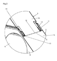
- a folding is arranged having at least one chute 10, as is shown in the cross sectional view of Fig. 2 .
- a corresponding folding is arranged having a bead 11 with a complementary form and placement at the edges of the end surface 12 of the respective panel member 2, 3.
- the respective bead 11 in the preferred embodiment is designed in the same way as a chute 10, but with an orientation and aim which makes it easily connectable with a chute 10 on an adjacent member.
- the chutes 10 and beads 11 have several functions.
- a first function is that the foldings with chutes 10 and beads 11 have a guiding function when the panel members shall be positioned in one and the same plane in order to be joined together with the optional fittings which are discussed above.
- the beads 11 cooperate with the chutes 10 the panel members 2, 3 are guided in their entirety to extend in the same plane, before the assembly, and distorsions in the growing-wall 1 established by the panel members 2, 3 are avoided.
- the guiding-in is sufficient for holding the members 2, 3 in place in relation to each other, and further anchoring is superfluous.
- interior fittings 19 are used, which are arranged around longitudinal, outwards angled flanges 19 on each of the two members 3 to be joined together, in order to provide a substantially vertical joint 20.
- Stabilizing plates 4 are arranged in the preferred embodiment in order to keep the filling 15 of the members 3 in place.
- the interior fittings 18 extend preferably over the whole or a larger part of the length of the vertical joint 20, but shorter variants of the fittings 18 are also conceivable. In that case they are arranged close to the end surfaces of the panel members 2, 3 in order to be accessible when joining together of the panel members 2, 3.
- further fittings which are previously known, such as different forms of flat bars or angle bars, can be used in order to anchor the growing-wall to a base or in relation to an upstanding surface, such as a wall.
- the supply of water takes place through a watering unit, which comprises a perforated drip hose, which extends upwards from a pump 16 coupled to a water supply.
- the water supply is controlled by controlling the pressure of the water coming from the pump 16. The pressure must be high enough to transport the water up to the upper end surface 5 of the upper element 3, and the exceeding pressure will decide the supplied amount of water to the growing-wall 1.
- a metering unit is also coupled to the pump 16 for the supply of nutrients to the water. Sensors for sensing the moisture content in the wall and the nutrient concentration in the supplied water is advantageously also included in the system for supply of water and nutrient.
- One alternative is that the supply of water and nutrient is controlled manually.
- Cover plates 21 are suitably arranged at the side edges and at the upper end surface 5, partly in order to prevent undesired evaporation, and partly in order to obtain an aesthetically advantageous look, where the open side surfaces of the panel members as well as the hoses for the supply of water are concealed.
- prefabricated insulating wall units are used as the panel members 2, 3.
- the described folding is present in some types of wall units, with the aim to prevent liquid from intruding inside of the surface layer.
- the existing wall units are intended to be mounted so that the end surfaces, which are provided with chutes, are turned downwards. As is described above an opposite function is obtained, i.e. a leakage from the inside and outwards is prevented if the wall units are turned upside down.
- a watering system comprising a drip hose, a collecting vessel 8 and a pump 16 must be arranged in the way described above.
- lead-throughs 6, as has been described above, have to be taken up in one or both of the surface layers 9.
- cover plates 21 are arranged at the end surfaces and side surfaces which are not arranged adjacent to any other wall unit. Further undesired evaporation is prevented, as was described above.
- insulated wall units of the type described make possible a god adjustment to the surroundings with its modules.
- the wall units also have the necessary qualities for interconnection, attachment and anchorage at walls also in this new field of use.
- the growing-wall according to the invention has a great number of fields of use, e.g. public areas, offices, shopping malls, parks, urban environments. It may also work as a noise barrier at roads, railways, airports or adjacent to machines, e.g. in factories. In all these functions both single and double faced growing-walls can be used.
Landscapes
- Life Sciences & Earth Sciences (AREA)
- Environmental Sciences (AREA)
- Cultivation Receptacles Or Flower-Pots, Or Pots For Seedlings (AREA)
Abstract
Description
- The invention relates to a means for vertical cultivation by growing of plants comprising a panel member arranged on its end having a outer layer, in which lead-throughs for plants are provided, and an upper end surface adjoining a front side as well as a back side of the panel member.
- The invention also relates to the use of an insulated wall unit in order to provide a means according to the above.
- Finally, the invention also relates to a method of providing such a means.
- There are prior art means for standing-up, substantially vertical, cultivation. One example of such a means is disclosed in
EP 24 28 110 . In this means a hydrophilic felt material is arranged between a rear, waterproof layer and a front surface layer, in which there are openings for plants. Further, there is comprised a net or grid in order to hold the felt material. All of the layers are soft so that the means can be wound up. A perforated tube is inserted at the top of the means for the supply of water and water soluble nutrients. Surplus water is let out at the bottom of the means through openings. The soft means is intended to be arranged at a wall or the like, partly since it is not self-supporting, and partly since it is one-sided. - The disclosed structure works relatively well, at least in some climates and for certain plant types, but still exhibits drawbacks. Since the water is drained at the bottom, it is only suitable for outside use, and then above such a ground where the water dripping out of the means does not cause damages or discoloration, which are difficult to remove. At the same time it is necessary to arrange it adjacent to a wall, which limits the option with regard to its placement.
-
FR 26 34 971 - Also this means has some disadvantages. Certainly, it is self-supporting and has a collecting vessel for taking care of superfluous water, but there is an immediate risk that it will be difficult to control the water supply. With a low feed and a high surrounding temperature there is a great risk that the evaporation from the felt material is so extensive that only the plants in the upper part of the means, close to the water supply, will get enough water. The evaporation can also result in a change of concentration of the nutrient in the water, which might affect sensitive plants negatively.
- A higher water feed can compensate for the loss through evaporation, but involves a risk that the plants in the upper part will be given to large amounts of water. Further, if the temperature drops, the evaporation will be reduced and there is a risk that also the plants in the lower part of the means will receive a too large water feed, which only partly can be compensated for by water being drained off at the lower edge of the means. The problems become more expressed with an increasing size of the means, since the evaporation is related to the surface of the means.
- Common for the two means is also that they are limited in size, and the possibilities of adjusting their size to the place where they are supposed to be placed are very small.
- Accordingly, there is a need for a means for vertical cultivation by growing where the size and placement are selectable at will, and wherein the water feed in the means is not problematic in the ways that have been described above.
- The aim of the invention will be achieved if the means described in the preamble is given the characterizing feature that the member along the edges of its upper end surface is provided with at least one elongated chute.
- Further advantages will be achieved if the means is also given one or several characterizing features according to the claims 2 -7.
- Regarding the method of providing the means, the aim is achieved if the method is characterized in that a prefabricated insulated wall unit is arranged so that an end surface having chutes is turned upwards, and in that lead-throughs are taken up through an outer layer of the member for the insertion of plants.
- Further advantages are achieved when the method is further given characterizing features according to
claim 10. - The invention will now be described with references to the accompanying drawings. In these the respective Figures show:
- Fig. 1
- a partly cut-up view in perspective of a means according to the invention comprising a number of panel members;
- Fig. 2
- a cross sectional view in perspective of a horizontal joint between two members according to
Fig. 1 ; and - Fig. 3
- a view according to
Fig. 2 showing a vertical joint between two panel members. - In
Fig. 1 is shown a growing-wall 1 according to the invention, comprising four mutually connectedpanel members members upper end surface 5 of theupper panel members 3. Thepanel members throughs 6 through theirsurface layers 9, at least on the sides intended to be their front sides 7, but also the back sides can be provided with lead-throughs 6 for those applications where a growing-wall having plants on both sides is desired. At the bottom, at the lower edge of thelower panel members 2, is arranged acollecting vessel 8 for collecting water oozing out from the bottom of thelower panel members 1. Apump 16 for supply of water to the growing-wall 1 is also arranged in association with thecollecting vessel 8. - Each of the
panel members surface layer 9, which, as is mentioned above, is completely or partly provided with lead-throughs 6. Plants are arranged in the lead-throughs 6, so that their roots extend inwards for a shorter or longer distance into thefilling 15 of therespective panel member - The lead-
throughs 6 can be arranged in different configurations, such as in rows and columns, in rows in which the lead-throughs 6 are displaced in relation to those on the row above, such as is shown inFig. 1 , in circles or in random configurations. - The
surface layer 9 consists of some suitable material, such as metal or hard plastic, which in itself is form-stable so that a self-supporting member is formed, which does not need any support to be kept standing in an upright, substantially vertical position. The material should also in principle be water impermeable, despite form the lead-throughs 6. Hereby water is prevented from evaporation through thesurface layer 9 in a hard-to-control way. The water which is not consumed by the plants will be led downwards through themember whole member - The
filling 15 is preferably a water absorbing insulation panel, which conducts water well. Superfluous water, which is not directly used by the plants, will not be retained, but is instead led downwards under the influence of gravity. There is no risk for the plants to receive to much water, since the superfluous water is led away. Since the water does not stand still there is no breeding ground for mildew or bad smell. - The
panel members wall 1 with an optional size and configuration can be built up. The upper and lower end surfaces on therespective member upper member 3 to alower member 2, and finally be drained at the very bottom to thecollecting vessel 8. In order to keep the above advantages with minimizing the losses of water and fertilizer, which pass through the member, it is desirable that the interconnection is free from leakage. It is further an aesthetic advantage, in case thesurface layer 9 of themembers - The
panel members Fig. 2 , a horizontal joint 13 is provided by folding the upper and lower edges, respectively, of the surface layers, so that these can be joined to each other. - Along the edges of the
upper end surface 5 on each of thepanel members chute 10, as is shown in the cross sectional view ofFig. 2 . In the preferred embodiment a corresponding folding is arranged having abead 11 with a complementary form and placement at the edges of theend surface 12 of therespective panel member respective bead 11 in the preferred embodiment is designed in the same way as achute 10, but with an orientation and aim which makes it easily connectable with achute 10 on an adjacent member. In the preferred embodiment there are foldings with thechute 10 and thebead 11 on each side of thepanel member chutes 10 andbeads 11 have several functions. - A first function is that the foldings with
chutes 10 andbeads 11 have a guiding function when the panel members shall be positioned in one and the same plane in order to be joined together with the optional fittings which are discussed above. When thebeads 11 cooperate with thechutes 10 thepanel members wall 1 established by thepanel members members - When the growing-
wall 1 is erected it is unavoidable that thejoints 13 between themembers panel members panel members chutes 10 and thebeads 11 along the large part of the joint 13. This will result in a considerably stronger joint 13. - Finally the folding will also prevent leakage through the joint 13 from its filling material to the outside. Water moving downwards inside the
upper panel member 3 will be caught in the inside of thebeads 11 to the extent it is transported close to thesurface layer 9. When the insides of thebeads 11 are filled up with water this will begin to ooze over theinner edge 14 of the bead and further down into thelower panel member 2. Inside thefoldings panel members respective panel member panel members panel members walls 1 of practically any size can be built up with thepanel members - In the preferred embodiment shown in the Figs., especially in
Fig. 3 ,interior fittings 19 are used, which are arranged around longitudinal, outwards angledflanges 19 on each of the twomembers 3 to be joined together, in order to provide a substantially vertical joint 20. Stabilizing plates 4 are arranged in the preferred embodiment in order to keep the filling 15 of themembers 3 in place. Theinterior fittings 18 extend preferably over the whole or a larger part of the length of the vertical joint 20, but shorter variants of thefittings 18 are also conceivable. In that case they are arranged close to the end surfaces of thepanel members panel members - If desired, further fittings, which are previously known, such as different forms of flat bars or angle bars, can be used in order to anchor the growing-wall to a base or in relation to an upstanding surface, such as a wall.
- The supply of water takes place through a watering unit, which comprises a perforated drip hose, which extends upwards from a
pump 16 coupled to a water supply. The water supply is controlled by controlling the pressure of the water coming from thepump 16. The pressure must be high enough to transport the water up to theupper end surface 5 of theupper element 3, and the exceeding pressure will decide the supplied amount of water to the growing-wall 1. In a preferred embodiment, a metering unit is also coupled to thepump 16 for the supply of nutrients to the water. Sensors for sensing the moisture content in the wall and the nutrient concentration in the supplied water is advantageously also included in the system for supply of water and nutrient. One alternative is that the supply of water and nutrient is controlled manually. - Since the evaporation from the growing-wall is minimal it will be easy to achieve an equilibrium condition wherein the amount of liquid consumed of the plant is supplied through the drip hose. The actual consumption is decisive for the watering demand, and a surplus will be drained to the collecting
vessel 8, where it can be recirculated to the growing-wall 1 through thepump 16. The liquid distribution within thewall 1 will be comparatively even, since water not taken up to a large degree will be transported on downwards. If the water supply is increased, an evenly distributed increase of the water resources will result in the whole growing-wall 1. -
Cover plates 21 are suitably arranged at the side edges and at theupper end surface 5, partly in order to prevent undesired evaporation, and partly in order to obtain an aesthetically advantageous look, where the open side surfaces of the panel members as well as the hoses for the supply of water are concealed. - An especially preferred variant of the invention, which is described immediately above, is that prefabricated insulating wall units are used as the
panel members surface layers 9 as well as a filling 15 of insulating material in place as a result of a rational manufacture in large series. Also the described folding is present in some types of wall units, with the aim to prevent liquid from intruding inside of the surface layer. In order to make this work the existing wall units are intended to be mounted so that the end surfaces, which are provided with chutes, are turned downwards. As is described above an opposite function is obtained, i.e. a leakage from the inside and outwards is prevented if the wall units are turned upside down. - However, certain adjustments of the existing, prefabricated wall units have to be made if the result shall be a growing-
wall 1 according to the invention. A watering system, comprising a drip hose, a collectingvessel 8 and apump 16 must be arranged in the way described above. Of course also lead-throughs 6, as has been described above, have to be taken up in one or both of the surface layers 9. - Further, it is an aesthetic advantage if
cover plates 21 are arranged at the end surfaces and side surfaces which are not arranged adjacent to any other wall unit. Further undesired evaporation is prevented, as was described above. In a special, advantageous embodiment there is also a control unit for automatic control of the pressure of the pump, based on the surrounding temperature and the moisture content of the wall. - Besides, insulated wall units of the type described make possible a god adjustment to the surroundings with its modules. The wall units also have the necessary qualities for interconnection, attachment and anchorage at walls also in this new field of use.
- Thus, the growing-wall according to the invention has a great number of fields of use, e.g. public areas, offices, shopping malls, parks, urban environments. It may also work as a noise barrier at roads, railways, airports or adjacent to machines, e.g. in factories. In all these functions both single and double faced growing-walls can be used.
- Finally should be mentioned the possibility to use tempered water inside the panel members. Because of the good insulating properties inside the members the risk for the water to freeze is reduced, and cultivation by growing in the growing-wall can be maintained also during colder periods with risk of frost.
- The invention can be further modified within the scope of the appended claims.
Claims (10)
- A means for vertical cultivation by growing of plants comprising a panel member (2, 3) arranged on its end having an outer layer (9), in which lead-throughs (6) for plants are provided, and an upper end surface (5) adjoining a front side as well as a back side of the panel member (2, 3), characterized in that the member (2, 3) is provided with at least one elongated chute (10) alongside the edges of its upper end surface (5).
- The means according to claim 1, characterized in that the panel member is provided with at least one elongated bead (11) alongside the edges of its lower end surface (12).
- The means according to claim 2, characterized in that the form of the bead (11) and the form of the chute (10) are complementary for interconnection of two panel members (2, 3).
- The means according to any of the claims 1 - 3, characterized in that the panel member (2, 3) has an interior filling (15) of insulating material.
- The means according to any of the claims 1 - 4, characterized in that a perforated hose for water supply to the panel member (2, 3) is arranged alongside its upper end surface (5).
- The means according to any of the claims 1 - 5, characterized in that a collecting vessel (8) is arranged beneath the lower edge of the panel member (2, 3) for collecting liquid therefrom.
- The means according to any of the claims 1 - 6, characterized in that an existing, prefabricated wall unit is used as panel member (2, 3).
- Use of an insulated wall unit for providing of a means (1) according to any of the claims 1 - 7.
- A method of providing a means according to any of the claims 1- 7, characterized in that a prefabricated, insulated wall unit (2, 3) is arranged in such a way that one end surface (5) having chutes (10) is turned upwards, and lead-throughs (6) through an outer layer (9) of the element (2, 3) are taken up for the insertion of plants.
- The method according to claim 9, characterized in that a number of wall units (2, 3) are arranged in such a way that at least one upper end surface (5) of a first wall unit (2) is arranged to adjoin a lower end surface (12) of a second wall unit (3).
Applications Claiming Priority (1)
| Application Number | Priority Date | Filing Date | Title |
|---|---|---|---|
| SE1300559A SE537507C2 (en) | 2013-08-26 | 2013-08-26 | Device for cultivation and methods for producing it |
Publications (1)
| Publication Number | Publication Date |
|---|---|
| EP2842415A1 true EP2842415A1 (en) | 2015-03-04 |
Family
ID=51752979
Family Applications (1)
| Application Number | Title | Priority Date | Filing Date |
|---|---|---|---|
| EP14182076.1A Withdrawn EP2842415A1 (en) | 2013-08-26 | 2014-08-25 | Means for vertical cultivation of plants and method of providing such means |
Country Status (2)
| Country | Link |
|---|---|
| EP (1) | EP2842415A1 (en) |
| SE (1) | SE537507C2 (en) |
Cited By (3)
| Publication number | Priority date | Publication date | Assignee | Title |
|---|---|---|---|---|
| DE102019132124A1 (en) * | 2019-11-27 | 2021-05-27 | Richard Brink Gmbh & Co. Kg | Kit for assembling a plantable wall garden |
| US11672215B2 (en) | 2020-01-12 | 2023-06-13 | Sentient Design, Inc. | Aeroponic plant growing system |
| USD1067000S1 (en) | 2020-08-11 | 2025-03-18 | Sentient Design, Inc. | Aeroponic plant growing system |
Citations (8)
| Publication number | Priority date | Publication date | Assignee | Title |
|---|---|---|---|---|
| FR2634971A1 (en) | 1988-08-08 | 1990-02-09 | Blanc Patrick | Device for growing plants without soil on a vertical surface |
| US20080000153A1 (en) * | 2005-01-07 | 2008-01-03 | Nobuo Sugiyama | Temporary Structural Body for Seeding and Planting |
| WO2010031181A1 (en) * | 2008-09-18 | 2010-03-25 | Eco Innovations Inc. | Plant propagation and display panel and assembly |
| WO2011014124A1 (en) * | 2009-07-31 | 2011-02-03 | Housing And Development Board | A plant housing device |
| US20110093122A1 (en) * | 2009-10-20 | 2011-04-21 | Sotiri Koumoudis | Green Wall Lighting and Irrigation Control System and Method |
| EP2428110A1 (en) | 2010-09-14 | 2012-03-14 | Gaia Eau Creation | Soilless plant cultivation device for a green wall |
| KR101234615B1 (en) * | 2012-02-03 | 2013-02-20 | 주식회사 그리움 | Planter for green wall |
| EP2564689A1 (en) * | 2011-08-30 | 2013-03-06 | Saint-Gogain Cultilene BV | Vegetated panel and associated vegetated wall |
-
2013
- 2013-08-26 SE SE1300559A patent/SE537507C2/en unknown
-
2014
- 2014-08-25 EP EP14182076.1A patent/EP2842415A1/en not_active Withdrawn
Patent Citations (8)
| Publication number | Priority date | Publication date | Assignee | Title |
|---|---|---|---|---|
| FR2634971A1 (en) | 1988-08-08 | 1990-02-09 | Blanc Patrick | Device for growing plants without soil on a vertical surface |
| US20080000153A1 (en) * | 2005-01-07 | 2008-01-03 | Nobuo Sugiyama | Temporary Structural Body for Seeding and Planting |
| WO2010031181A1 (en) * | 2008-09-18 | 2010-03-25 | Eco Innovations Inc. | Plant propagation and display panel and assembly |
| WO2011014124A1 (en) * | 2009-07-31 | 2011-02-03 | Housing And Development Board | A plant housing device |
| US20110093122A1 (en) * | 2009-10-20 | 2011-04-21 | Sotiri Koumoudis | Green Wall Lighting and Irrigation Control System and Method |
| EP2428110A1 (en) | 2010-09-14 | 2012-03-14 | Gaia Eau Creation | Soilless plant cultivation device for a green wall |
| EP2564689A1 (en) * | 2011-08-30 | 2013-03-06 | Saint-Gogain Cultilene BV | Vegetated panel and associated vegetated wall |
| KR101234615B1 (en) * | 2012-02-03 | 2013-02-20 | 주식회사 그리움 | Planter for green wall |
Cited By (4)
| Publication number | Priority date | Publication date | Assignee | Title |
|---|---|---|---|---|
| DE102019132124A1 (en) * | 2019-11-27 | 2021-05-27 | Richard Brink Gmbh & Co. Kg | Kit for assembling a plantable wall garden |
| DE102019132124B4 (en) | 2019-11-27 | 2023-02-23 | Richard Brink Gmbh & Co. Kg | Kit for assembling a plantable wall garden |
| US11672215B2 (en) | 2020-01-12 | 2023-06-13 | Sentient Design, Inc. | Aeroponic plant growing system |
| USD1067000S1 (en) | 2020-08-11 | 2025-03-18 | Sentient Design, Inc. | Aeroponic plant growing system |
Also Published As
| Publication number | Publication date |
|---|---|
| SE537507C2 (en) | 2015-05-26 |
| SE1300559A1 (en) | 2015-02-27 |
Similar Documents
| Publication | Publication Date | Title |
|---|---|---|
| US8234814B2 (en) | Plant growing assembly | |
| US10383287B2 (en) | Vertical planter for growing plants | |
| RU2553649C2 (en) | Device for vertical or inclined placement of crops out of topsoil | |
| US7788848B1 (en) | Green wall planting module, support structure and irrigation control system | |
| KR101125247B1 (en) | A water culture device having had multilayer structure | |
| US9374947B2 (en) | Wall planting module | |
| EP2885963B1 (en) | Vertical garden | |
| JP6249153B2 (en) | Vertical plant cultivation equipment | |
| CN103262783A (en) | Three-dimensional soil-less cultivating device | |
| US11399474B2 (en) | Integrated fence irrigation and grow system | |
| WO2009122210A1 (en) | A planting tray | |
| EP3533319A1 (en) | Verticle grow box module and module and system of vertical grow boxes that incorporates it | |
| TW201605328A (en) | Grow board and method | |
| EP2842415A1 (en) | Means for vertical cultivation of plants and method of providing such means | |
| EP0222755A1 (en) | System for the water-culture of plants on a capillary substrate within a light-selective film | |
| KR101726567B1 (en) | Vertical Typed Apparatus For Cultivating Plant | |
| CN107105621A (en) | Culture apparatus and cultural method | |
| US20150334926A1 (en) | Plantation installation | |
| AU2006274753A1 (en) | Vegetated wall and constitutive elements thereof | |
| US20130333281A1 (en) | Apparatus and system for growing plants | |
| US20110232185A1 (en) | Collapsible rack and row planters | |
| JP4928992B2 (en) | Bottom irrigation water supply panel, cultivation pot for the panel, and cultivation system using them | |
| KR101828846B1 (en) | Vertical Typed Apparatus For Cultivating Plant | |
| KR20130131822A (en) | Cultivation system | |
| JP2010029096A (en) | Multistage container-type cultivation device |
Legal Events
| Date | Code | Title | Description |
|---|---|---|---|
| 17P | Request for examination filed |
Effective date: 20140825 |
|
| AK | Designated contracting states |
Kind code of ref document: A1 Designated state(s): AL AT BE BG CH CY CZ DE DK EE ES FI FR GB GR HR HU IE IS IT LI LT LU LV MC MK MT NL NO PL PT RO RS SE SI SK SM TR |
|
| AX | Request for extension of the european patent |
Extension state: BA ME |
|
| PUAI | Public reference made under article 153(3) epc to a published international application that has entered the european phase |
Free format text: ORIGINAL CODE: 0009012 |
|
| R17P | Request for examination filed (corrected) |
Effective date: 20150904 |
|
| RBV | Designated contracting states (corrected) |
Designated state(s): AL AT BE BG CH CY CZ DE DK EE ES FI FR GB GR HR HU IE IS IT LI LT LU LV MC MK MT NL NO PL PT RO RS SE SI SK SM TR |
|
| GRAP | Despatch of communication of intention to grant a patent |
Free format text: ORIGINAL CODE: EPIDOSNIGR1 |
|
| STAA | Information on the status of an ep patent application or granted ep patent |
Free format text: STATUS: GRANT OF PATENT IS INTENDED |
|
| INTG | Intention to grant announced |
Effective date: 20200720 |
|
| STAA | Information on the status of an ep patent application or granted ep patent |
Free format text: STATUS: THE APPLICATION IS DEEMED TO BE WITHDRAWN |
|
| 18D | Application deemed to be withdrawn |
Effective date: 20201201 |