EP2840704A1 - Retarder - Google Patents
Retarder Download PDFInfo
- Publication number
- EP2840704A1 EP2840704A1 EP13777862.7A EP13777862A EP2840704A1 EP 2840704 A1 EP2840704 A1 EP 2840704A1 EP 13777862 A EP13777862 A EP 13777862A EP 2840704 A1 EP2840704 A1 EP 2840704A1
- Authority
- EP
- European Patent Office
- Prior art keywords
- induction motor
- rotation speed
- vehicle
- control
- transmission
- Prior art date
- Legal status (The legal status is an assumption and is not a legal conclusion. Google has not performed a legal analysis and makes no representation as to the accuracy of the status listed.)
- Withdrawn
Links
Images


Classifications
-
- B—PERFORMING OPERATIONS; TRANSPORTING
- B60—VEHICLES IN GENERAL
- B60L—PROPULSION OF ELECTRICALLY-PROPELLED VEHICLES; SUPPLYING ELECTRIC POWER FOR AUXILIARY EQUIPMENT OF ELECTRICALLY-PROPELLED VEHICLES; ELECTRODYNAMIC BRAKE SYSTEMS FOR VEHICLES IN GENERAL; MAGNETIC SUSPENSION OR LEVITATION FOR VEHICLES; MONITORING OPERATING VARIABLES OF ELECTRICALLY-PROPELLED VEHICLES; ELECTRIC SAFETY DEVICES FOR ELECTRICALLY-PROPELLED VEHICLES
- B60L7/00—Electrodynamic brake systems for vehicles in general
- B60L7/10—Dynamic electric regenerative braking
- B60L7/14—Dynamic electric regenerative braking for vehicles propelled by AC motors
-
- B—PERFORMING OPERATIONS; TRANSPORTING
- B60—VEHICLES IN GENERAL
- B60K—ARRANGEMENT OR MOUNTING OF PROPULSION UNITS OR OF TRANSMISSIONS IN VEHICLES; ARRANGEMENT OR MOUNTING OF PLURAL DIVERSE PRIME-MOVERS IN VEHICLES; AUXILIARY DRIVES FOR VEHICLES; INSTRUMENTATION OR DASHBOARDS FOR VEHICLES; ARRANGEMENTS IN CONNECTION WITH COOLING, AIR INTAKE, GAS EXHAUST OR FUEL SUPPLY OF PROPULSION UNITS IN VEHICLES
- B60K6/00—Arrangement or mounting of plural diverse prime-movers for mutual or common propulsion, e.g. hybrid propulsion systems comprising electric motors and internal combustion engines
- B60K6/20—Arrangement or mounting of plural diverse prime-movers for mutual or common propulsion, e.g. hybrid propulsion systems comprising electric motors and internal combustion engines the prime-movers consisting of electric motors and internal combustion engines, e.g. HEVs
- B60K6/42—Arrangement or mounting of plural diverse prime-movers for mutual or common propulsion, e.g. hybrid propulsion systems comprising electric motors and internal combustion engines the prime-movers consisting of electric motors and internal combustion engines, e.g. HEVs characterised by the architecture of the hybrid electric vehicle
- B60K6/48—Parallel type
-
- B—PERFORMING OPERATIONS; TRANSPORTING
- B60—VEHICLES IN GENERAL
- B60L—PROPULSION OF ELECTRICALLY-PROPELLED VEHICLES; SUPPLYING ELECTRIC POWER FOR AUXILIARY EQUIPMENT OF ELECTRICALLY-PROPELLED VEHICLES; ELECTRODYNAMIC BRAKE SYSTEMS FOR VEHICLES IN GENERAL; MAGNETIC SUSPENSION OR LEVITATION FOR VEHICLES; MONITORING OPERATING VARIABLES OF ELECTRICALLY-PROPELLED VEHICLES; ELECTRIC SAFETY DEVICES FOR ELECTRICALLY-PROPELLED VEHICLES
- B60L15/00—Methods, circuits, or devices for controlling the traction-motor speed of electrically-propelled vehicles
- B60L15/20—Methods, circuits, or devices for controlling the traction-motor speed of electrically-propelled vehicles for control of the vehicle or its driving motor to achieve a desired performance, e.g. speed, torque, programmed variation of speed
- B60L15/2009—Methods, circuits, or devices for controlling the traction-motor speed of electrically-propelled vehicles for control of the vehicle or its driving motor to achieve a desired performance, e.g. speed, torque, programmed variation of speed for braking
-
- B—PERFORMING OPERATIONS; TRANSPORTING
- B60—VEHICLES IN GENERAL
- B60L—PROPULSION OF ELECTRICALLY-PROPELLED VEHICLES; SUPPLYING ELECTRIC POWER FOR AUXILIARY EQUIPMENT OF ELECTRICALLY-PROPELLED VEHICLES; ELECTRODYNAMIC BRAKE SYSTEMS FOR VEHICLES IN GENERAL; MAGNETIC SUSPENSION OR LEVITATION FOR VEHICLES; MONITORING OPERATING VARIABLES OF ELECTRICALLY-PROPELLED VEHICLES; ELECTRIC SAFETY DEVICES FOR ELECTRICALLY-PROPELLED VEHICLES
- B60L50/00—Electric propulsion with power supplied within the vehicle
- B60L50/10—Electric propulsion with power supplied within the vehicle using propulsion power supplied by engine-driven generators, e.g. generators driven by combustion engines
- B60L50/16—Electric propulsion with power supplied within the vehicle using propulsion power supplied by engine-driven generators, e.g. generators driven by combustion engines with provision for separate direct mechanical propulsion
-
- B—PERFORMING OPERATIONS; TRANSPORTING
- B60—VEHICLES IN GENERAL
- B60K—ARRANGEMENT OR MOUNTING OF PROPULSION UNITS OR OF TRANSMISSIONS IN VEHICLES; ARRANGEMENT OR MOUNTING OF PLURAL DIVERSE PRIME-MOVERS IN VEHICLES; AUXILIARY DRIVES FOR VEHICLES; INSTRUMENTATION OR DASHBOARDS FOR VEHICLES; ARRANGEMENTS IN CONNECTION WITH COOLING, AIR INTAKE, GAS EXHAUST OR FUEL SUPPLY OF PROPULSION UNITS IN VEHICLES
- B60K6/00—Arrangement or mounting of plural diverse prime-movers for mutual or common propulsion, e.g. hybrid propulsion systems comprising electric motors and internal combustion engines
- B60K6/20—Arrangement or mounting of plural diverse prime-movers for mutual or common propulsion, e.g. hybrid propulsion systems comprising electric motors and internal combustion engines the prime-movers consisting of electric motors and internal combustion engines, e.g. HEVs
- B60K6/42—Arrangement or mounting of plural diverse prime-movers for mutual or common propulsion, e.g. hybrid propulsion systems comprising electric motors and internal combustion engines the prime-movers consisting of electric motors and internal combustion engines, e.g. HEVs characterised by the architecture of the hybrid electric vehicle
- B60K6/48—Parallel type
- B60K2006/4808—Electric machine connected or connectable to gearbox output shaft
-
- B—PERFORMING OPERATIONS; TRANSPORTING
- B60—VEHICLES IN GENERAL
- B60L—PROPULSION OF ELECTRICALLY-PROPELLED VEHICLES; SUPPLYING ELECTRIC POWER FOR AUXILIARY EQUIPMENT OF ELECTRICALLY-PROPELLED VEHICLES; ELECTRODYNAMIC BRAKE SYSTEMS FOR VEHICLES IN GENERAL; MAGNETIC SUSPENSION OR LEVITATION FOR VEHICLES; MONITORING OPERATING VARIABLES OF ELECTRICALLY-PROPELLED VEHICLES; ELECTRIC SAFETY DEVICES FOR ELECTRICALLY-PROPELLED VEHICLES
- B60L2210/00—Converter types
- B60L2210/40—DC to AC converters
-
- B—PERFORMING OPERATIONS; TRANSPORTING
- B60—VEHICLES IN GENERAL
- B60L—PROPULSION OF ELECTRICALLY-PROPELLED VEHICLES; SUPPLYING ELECTRIC POWER FOR AUXILIARY EQUIPMENT OF ELECTRICALLY-PROPELLED VEHICLES; ELECTRODYNAMIC BRAKE SYSTEMS FOR VEHICLES IN GENERAL; MAGNETIC SUSPENSION OR LEVITATION FOR VEHICLES; MONITORING OPERATING VARIABLES OF ELECTRICALLY-PROPELLED VEHICLES; ELECTRIC SAFETY DEVICES FOR ELECTRICALLY-PROPELLED VEHICLES
- B60L2220/00—Electrical machine types; Structures or applications thereof
- B60L2220/10—Electrical machine types
- B60L2220/12—Induction machines
-
- B—PERFORMING OPERATIONS; TRANSPORTING
- B60—VEHICLES IN GENERAL
- B60L—PROPULSION OF ELECTRICALLY-PROPELLED VEHICLES; SUPPLYING ELECTRIC POWER FOR AUXILIARY EQUIPMENT OF ELECTRICALLY-PROPELLED VEHICLES; ELECTRODYNAMIC BRAKE SYSTEMS FOR VEHICLES IN GENERAL; MAGNETIC SUSPENSION OR LEVITATION FOR VEHICLES; MONITORING OPERATING VARIABLES OF ELECTRICALLY-PROPELLED VEHICLES; ELECTRIC SAFETY DEVICES FOR ELECTRICALLY-PROPELLED VEHICLES
- B60L2240/00—Control parameters of input or output; Target parameters
- B60L2240/10—Vehicle control parameters
- B60L2240/12—Speed
-
- B—PERFORMING OPERATIONS; TRANSPORTING
- B60—VEHICLES IN GENERAL
- B60L—PROPULSION OF ELECTRICALLY-PROPELLED VEHICLES; SUPPLYING ELECTRIC POWER FOR AUXILIARY EQUIPMENT OF ELECTRICALLY-PROPELLED VEHICLES; ELECTRODYNAMIC BRAKE SYSTEMS FOR VEHICLES IN GENERAL; MAGNETIC SUSPENSION OR LEVITATION FOR VEHICLES; MONITORING OPERATING VARIABLES OF ELECTRICALLY-PROPELLED VEHICLES; ELECTRIC SAFETY DEVICES FOR ELECTRICALLY-PROPELLED VEHICLES
- B60L2240/00—Control parameters of input or output; Target parameters
- B60L2240/40—Drive Train control parameters
- B60L2240/42—Drive Train control parameters related to electric machines
- B60L2240/421—Speed
-
- B—PERFORMING OPERATIONS; TRANSPORTING
- B60—VEHICLES IN GENERAL
- B60L—PROPULSION OF ELECTRICALLY-PROPELLED VEHICLES; SUPPLYING ELECTRIC POWER FOR AUXILIARY EQUIPMENT OF ELECTRICALLY-PROPELLED VEHICLES; ELECTRODYNAMIC BRAKE SYSTEMS FOR VEHICLES IN GENERAL; MAGNETIC SUSPENSION OR LEVITATION FOR VEHICLES; MONITORING OPERATING VARIABLES OF ELECTRICALLY-PROPELLED VEHICLES; ELECTRIC SAFETY DEVICES FOR ELECTRICALLY-PROPELLED VEHICLES
- B60L2240/00—Control parameters of input or output; Target parameters
- B60L2240/40—Drive Train control parameters
- B60L2240/42—Drive Train control parameters related to electric machines
- B60L2240/423—Torque
-
- B—PERFORMING OPERATIONS; TRANSPORTING
- B60—VEHICLES IN GENERAL
- B60L—PROPULSION OF ELECTRICALLY-PROPELLED VEHICLES; SUPPLYING ELECTRIC POWER FOR AUXILIARY EQUIPMENT OF ELECTRICALLY-PROPELLED VEHICLES; ELECTRODYNAMIC BRAKE SYSTEMS FOR VEHICLES IN GENERAL; MAGNETIC SUSPENSION OR LEVITATION FOR VEHICLES; MONITORING OPERATING VARIABLES OF ELECTRICALLY-PROPELLED VEHICLES; ELECTRIC SAFETY DEVICES FOR ELECTRICALLY-PROPELLED VEHICLES
- B60L2240/00—Control parameters of input or output; Target parameters
- B60L2240/40—Drive Train control parameters
- B60L2240/42—Drive Train control parameters related to electric machines
- B60L2240/425—Temperature
-
- B—PERFORMING OPERATIONS; TRANSPORTING
- B60—VEHICLES IN GENERAL
- B60L—PROPULSION OF ELECTRICALLY-PROPELLED VEHICLES; SUPPLYING ELECTRIC POWER FOR AUXILIARY EQUIPMENT OF ELECTRICALLY-PROPELLED VEHICLES; ELECTRODYNAMIC BRAKE SYSTEMS FOR VEHICLES IN GENERAL; MAGNETIC SUSPENSION OR LEVITATION FOR VEHICLES; MONITORING OPERATING VARIABLES OF ELECTRICALLY-PROPELLED VEHICLES; ELECTRIC SAFETY DEVICES FOR ELECTRICALLY-PROPELLED VEHICLES
- B60L2240/00—Control parameters of input or output; Target parameters
- B60L2240/40—Drive Train control parameters
- B60L2240/44—Drive Train control parameters related to combustion engines
- B60L2240/441—Speed
-
- B—PERFORMING OPERATIONS; TRANSPORTING
- B60—VEHICLES IN GENERAL
- B60L—PROPULSION OF ELECTRICALLY-PROPELLED VEHICLES; SUPPLYING ELECTRIC POWER FOR AUXILIARY EQUIPMENT OF ELECTRICALLY-PROPELLED VEHICLES; ELECTRODYNAMIC BRAKE SYSTEMS FOR VEHICLES IN GENERAL; MAGNETIC SUSPENSION OR LEVITATION FOR VEHICLES; MONITORING OPERATING VARIABLES OF ELECTRICALLY-PROPELLED VEHICLES; ELECTRIC SAFETY DEVICES FOR ELECTRICALLY-PROPELLED VEHICLES
- B60L2240/00—Control parameters of input or output; Target parameters
- B60L2240/40—Drive Train control parameters
- B60L2240/44—Drive Train control parameters related to combustion engines
- B60L2240/443—Torque
-
- B—PERFORMING OPERATIONS; TRANSPORTING
- B60—VEHICLES IN GENERAL
- B60L—PROPULSION OF ELECTRICALLY-PROPELLED VEHICLES; SUPPLYING ELECTRIC POWER FOR AUXILIARY EQUIPMENT OF ELECTRICALLY-PROPELLED VEHICLES; ELECTRODYNAMIC BRAKE SYSTEMS FOR VEHICLES IN GENERAL; MAGNETIC SUSPENSION OR LEVITATION FOR VEHICLES; MONITORING OPERATING VARIABLES OF ELECTRICALLY-PROPELLED VEHICLES; ELECTRIC SAFETY DEVICES FOR ELECTRICALLY-PROPELLED VEHICLES
- B60L2240/00—Control parameters of input or output; Target parameters
- B60L2240/40—Drive Train control parameters
- B60L2240/48—Drive Train control parameters related to transmissions
- B60L2240/486—Operating parameters
-
- B—PERFORMING OPERATIONS; TRANSPORTING
- B60—VEHICLES IN GENERAL
- B60W—CONJOINT CONTROL OF VEHICLE SUB-UNITS OF DIFFERENT TYPE OR DIFFERENT FUNCTION; CONTROL SYSTEMS SPECIALLY ADAPTED FOR HYBRID VEHICLES; ROAD VEHICLE DRIVE CONTROL SYSTEMS FOR PURPOSES NOT RELATED TO THE CONTROL OF A PARTICULAR SUB-UNIT
- B60W2510/00—Input parameters relating to a particular sub-units
- B60W2510/02—Clutches
- B60W2510/0208—Clutch engagement state, e.g. engaged or disengaged
-
- B—PERFORMING OPERATIONS; TRANSPORTING
- B60—VEHICLES IN GENERAL
- B60W—CONJOINT CONTROL OF VEHICLE SUB-UNITS OF DIFFERENT TYPE OR DIFFERENT FUNCTION; CONTROL SYSTEMS SPECIALLY ADAPTED FOR HYBRID VEHICLES; ROAD VEHICLE DRIVE CONTROL SYSTEMS FOR PURPOSES NOT RELATED TO THE CONTROL OF A PARTICULAR SUB-UNIT
- B60W2510/00—Input parameters relating to a particular sub-units
- B60W2510/06—Combustion engines, Gas turbines
- B60W2510/0638—Engine speed
- B60W2510/0652—Speed change rate
-
- B—PERFORMING OPERATIONS; TRANSPORTING
- B60—VEHICLES IN GENERAL
- B60W—CONJOINT CONTROL OF VEHICLE SUB-UNITS OF DIFFERENT TYPE OR DIFFERENT FUNCTION; CONTROL SYSTEMS SPECIALLY ADAPTED FOR HYBRID VEHICLES; ROAD VEHICLE DRIVE CONTROL SYSTEMS FOR PURPOSES NOT RELATED TO THE CONTROL OF A PARTICULAR SUB-UNIT
- B60W2510/00—Input parameters relating to a particular sub-units
- B60W2510/10—Change speed gearings
- B60W2510/1005—Transmission ratio engaged
- B60W2510/101—Transmission neutral state
-
- Y—GENERAL TAGGING OF NEW TECHNOLOGICAL DEVELOPMENTS; GENERAL TAGGING OF CROSS-SECTIONAL TECHNOLOGIES SPANNING OVER SEVERAL SECTIONS OF THE IPC; TECHNICAL SUBJECTS COVERED BY FORMER USPC CROSS-REFERENCE ART COLLECTIONS [XRACs] AND DIGESTS
- Y02—TECHNOLOGIES OR APPLICATIONS FOR MITIGATION OR ADAPTATION AGAINST CLIMATE CHANGE
- Y02T—CLIMATE CHANGE MITIGATION TECHNOLOGIES RELATED TO TRANSPORTATION
- Y02T10/00—Road transport of goods or passengers
- Y02T10/60—Other road transportation technologies with climate change mitigation effect
- Y02T10/62—Hybrid vehicles
-
- Y—GENERAL TAGGING OF NEW TECHNOLOGICAL DEVELOPMENTS; GENERAL TAGGING OF CROSS-SECTIONAL TECHNOLOGIES SPANNING OVER SEVERAL SECTIONS OF THE IPC; TECHNICAL SUBJECTS COVERED BY FORMER USPC CROSS-REFERENCE ART COLLECTIONS [XRACs] AND DIGESTS
- Y02—TECHNOLOGIES OR APPLICATIONS FOR MITIGATION OR ADAPTATION AGAINST CLIMATE CHANGE
- Y02T—CLIMATE CHANGE MITIGATION TECHNOLOGIES RELATED TO TRANSPORTATION
- Y02T10/00—Road transport of goods or passengers
- Y02T10/60—Other road transportation technologies with climate change mitigation effect
- Y02T10/64—Electric machine technologies in electromobility
-
- Y—GENERAL TAGGING OF NEW TECHNOLOGICAL DEVELOPMENTS; GENERAL TAGGING OF CROSS-SECTIONAL TECHNOLOGIES SPANNING OVER SEVERAL SECTIONS OF THE IPC; TECHNICAL SUBJECTS COVERED BY FORMER USPC CROSS-REFERENCE ART COLLECTIONS [XRACs] AND DIGESTS
- Y02—TECHNOLOGIES OR APPLICATIONS FOR MITIGATION OR ADAPTATION AGAINST CLIMATE CHANGE
- Y02T—CLIMATE CHANGE MITIGATION TECHNOLOGIES RELATED TO TRANSPORTATION
- Y02T10/00—Road transport of goods or passengers
- Y02T10/60—Other road transportation technologies with climate change mitigation effect
- Y02T10/7072—Electromobility specific charging systems or methods for batteries, ultracapacitors, supercapacitors or double-layer capacitors
-
- Y—GENERAL TAGGING OF NEW TECHNOLOGICAL DEVELOPMENTS; GENERAL TAGGING OF CROSS-SECTIONAL TECHNOLOGIES SPANNING OVER SEVERAL SECTIONS OF THE IPC; TECHNICAL SUBJECTS COVERED BY FORMER USPC CROSS-REFERENCE ART COLLECTIONS [XRACs] AND DIGESTS
- Y02—TECHNOLOGIES OR APPLICATIONS FOR MITIGATION OR ADAPTATION AGAINST CLIMATE CHANGE
- Y02T—CLIMATE CHANGE MITIGATION TECHNOLOGIES RELATED TO TRANSPORTATION
- Y02T10/00—Road transport of goods or passengers
- Y02T10/60—Other road transportation technologies with climate change mitigation effect
- Y02T10/72—Electric energy management in electromobility
Definitions
- the present invention relates to a retarder used in a vehicle, and more particularly to a retarder equipped with an induction motor capable of performing brake application, electric power generation, and torque generation.
- the engines mounted on vehicles tend to be downsized.
- the downsizing of the engines reduces the effect of exhaust brake and engine brake, and necessitates the combined use of retarders for assisting in braking ability of vehicles.
- eddy current systems and fluid systems are commonly known, but with respect to the eddy current retarders of these systems, conventional eddy current retarders have been neither able to generate electric power nor regenerate energy generated during braking so that they have not been unable to satisfy the recent demand for low energy consumption. Further, such retarders have not been able to produce driving torque by themselves for assisting in the engine output so that they have not been used as auxiliary power of vehicles.
- the principle of the sensor-less control proposed in the past is to detect a deviation between the theoretical value and the actual value in induced electromotive force generated in the stator when the rotor is controlled so as to rotate at a predetermined rotation speed, and to estimate and control the rotation speed of the rotor by controlling the command value of rotation speed based on the amount of deviation.
- the method allows the control according to the principle if rotation control is performed from the state in which the rotor is stopped, but if the rotation control is performed from the state in which the rotor is rotating, the control according to the principle cannot be performed because the amount of deviation described above may become excessive depending on the operation state of the rotor at the time of control and stable control becomes difficult.
- the present invention has been developed in view of the circumstances described above, and it is an object of the present invention to provide, in retarders equipped with induction motors, a retarder capable of performing accurate sensor-less control regardless of the operation state of the motor.
- a retarder of the present invention is a retarder used in a vehicle in which an axle is driven by an internal combustion engine via a transmission, the retarder including an induction motor coupled to an output shaft of the transmission, and a control means that derives a rotation speed of the induction motor based on information detected by a rotation speed sensor for the internal combustion engine provided in the vehicle and information indicating a gear state of the transmission obtained from the vehicle, and controls the induction motor based on the derived rotation speed.
- the transmission may be any type of transmission, such as MT (Manual Transmission), AT (Automatic Transmission), CVT (Continuously Variable Transmission), or the like.
- MT Manual Transmission
- AT Automatic Transmission
- CVT Continuous Variable Transmission
- the "information detected by a rotation speed sensor for the internal combustion engine (engine)” may be any signal as long as it corresponds to the rotation speed of the engine, such as the output signal of the engine rotation speed sensor itself (e.g., a signal so-called a rotation pulse signal), a digital signal corresponding to the engine rotation speed flowing through an in-vehicle digital communication system, such as CAN (Controlled Area Network), or the like.
- the "information indicating a gear state” may be any form of information as long as it eventually allows the speed reduction ratio of the transmission to be identified other than information of gear stage (including neutral). In a case where the control means obtains only the gear stage from the vehicle side, information of reduction rate at each gear stage needs to be obtained in advance.
- the phrase "derives a rotation speed of the induction motor based on information detected by a rotation speed sensor for the internal combustion engine and information indicating a gear state of the transmission obtained from the vehicle” refers to obtain information of speed which is proportional to the rotation speed of the output shaft of the transmission, for example, by diving the rotation speed of the internal combustion engine by the speed reduction ratio of the transmission or the like.
- the control means may be a means that, if a variation in rotation speed of the internal combustion engine per unit time exceeds a predetermined threshold value, i.e., if the rotation speed of the internal combustion engine is increased rapidly, puts the induction motor into uncontrolled state in which any control to the induction motor is stopped or controls the induction motor such that neither driving torque nor braking torque is generated, assuming that the clutch is being disconnected or the gear is being in neutral.
- control means may be a means that puts the induction motor into uncontrolled state in which any control to the induction motor is stopped or controls the induction motor such that neither driving torque nor braking torque is generated if information indicating disconnection of a clutch provided in the vehicle is obtained or if the gear of the transmission is in neutral.
- the induction motor may be controlled based also on the information detected by the vehicle speed sensor.
- the induction motor may be controlled by the processing easier than to derive the rotation speed of the induction motor (i.e., rotation speed of the output shaft of the transmission) based on the information detected by the rotation speed sensor for the internal combustion engine and the information indicating the gear state of the transmission.
- the speed detection accuracy of the rotation speed sensor for the internal combustion engine which is a sensor identical to the vehicle speed sensor is not so high in the low speed region as in the vehicle speed sensor, but, unless the speed reduction ratio of the transmission falls below 1, the rotation speed of the rotation speed sensor for the internal combustion engine is higher than that of the vehicle speed sensor, so that higher speed detection accuracy may be obtained by deriving the rotation speed of the induction motor based on the information detected by the rotation speed sensor for the internal combustion engine and the information indicating the gear state of the transmission under such circumstances.
- control means may further include a function to control the induction motor based on information detected by a vehicle speed sensor provided in the vehicle, and the control means may be a means that performs switching, based on at least one of the information detected by the vehicle speed sensor and the information indicating a gear state of the transmission, whether to control the induction motor based on the information detected by the rotation speed sensor and the information indicating a gear state of the transmission or to control the induction motor based on the information detected by the vehicle speed sensor.
- the "information detected by a vehicle speed sensor provided in the vehicle” may be any signal as long as it corresponds to the vehicle speed, such as the output signal of the vehicle speed sensor itself (e.g., a signal so-called a vehicle speed pulse signal), a digital signal corresponding to the vehicle speed flowing through an in-vehicle digital communication system, such as CAN (Controlled Area Network), or the like.
- a vehicle speed pulse signal e.g., a signal so-called a vehicle speed pulse signal
- a digital signal corresponding to the vehicle speed flowing through an in-vehicle digital communication system such as CAN (Controlled Area Network), or the like.
- control the induction motor based on the information detected by the vehicle speed sensor refers to control the induction motor based on the information described above and if, for example, the induction motor is controlled based on the vehicle speed pulse signal, the control circuit (control means) of the retarder is configured to control the induction motor based on the output signal of the rotation speed sensor originally provided in the induction motor, such as a resolver, because the vehicle speed sensor generally detects the rotation speed of the output shaft of the transmission to which the induction motor is coupled, and if the output signal of the rotation speed sensor original provided in the induction motor is identical to the vehicle speed pulse signal, the received vehicle speed pulse signal may be deemed as the output signal of the rotation speed sensor and the existing control circuit of the induction motor may be used directly.
- the control circuit (control means) of the retarder is configured to control the induction motor based on the output signal of the rotation speed sensor originally provided in the induction motor, such as a resolver, because the vehicle speed sensor generally detects the rotation speed of the output shaft of the transmission to which the
- control circuit (control means) of the retarder is configured to control the induction motor based on the output signal of the rotation speed sensor originally provided in the induction motor, if the output signal of the rotation speed sensor originally provided in the induction motor and the vehicle speed pulse signal are different types of signals or if a digital signal corresponding to the vehicle speed flowing through the in-vehicle digital communication system, such as CAN (Controller Area Network), is received, the received signal needs to be converted so as to correspond to the signal indicating the rotation speed of the induction motor in the control circuit of the induction motor.
- CAN Controller Area Network
- control means may be a means that derives a rotation speed of the induction motor based on the information detected by the vehicle speed sensor and controls the induction motor based on the derived rotation speed.
- a control method of the present invention is a method in a retarder used in a vehicle in which an axle is driven by an internal combustion engine via a transmission, the method controlling an induction motor coupled to an output shaft of the transmission, wherein the method derives a rotation speed of the induction motor based on information detected by a rotation speed sensor for the internal combustion engine provided in the vehicle and information indicating a gear state of the transmission obtained from the vehicle, and controls the induction motor based on the derived rotation speed.
- the control method of the present invention may put the induction motor into uncontrolled state in which any control to the induction motor is stopped or controls the induction motor such that neither driving torque nor braking torque is generated if a variation in rotation speed of the internal combustion engine per unit time exceeds a predetermined threshold value.
- control method may put the induction motor into uncontrolled state in which any control to the induction motor is stopped or controls the induction motor such that neither driving torque nor braking torque is generated if information indicating disconnection of a clutch provided in the vehicle is obtained or if the gear of the transmission is in neutral.
- control method may further obtain information detected by a vehicle speed sensor provided in the vehicle and the method may perform switching, based on at least one of the information detected by the vehicle speed sensor and the information indicating a gear state of the transmission, whether to control the induction motor based on the information detected by the rotation speed sensor and the information indicating a gear state of the transmission or to control the induction motor based on the information detected by the vehicle speed sensor.
- control method may derive a rotation speed of the induction motor based on the information detected by the vehicle speed sensor and control the induction motor based on the derived rotation speed.
- a rotation speed of an induction motor is derived based on information detected by a rotation speed sensor for the internal combustion engine provided in the vehicle and information indicating a gear state of the transmission obtained from the vehicle, and the induction motor is controlled based on the derived rotation speed, thereby allowing the rotation speed of the induction motor to be obtained without mounting a rotation speed sensor on the induction motor.
- This allows accurate sensor-less control regardless of the operation state of the motor with low cost.
- the retarder of the present invention may be applied to any type of vehicle regardless of the type of vehicle on which it is mounted.
- the retarder may be prevented from falling into a dangerous operating condition based on inaccurate information by putting the induction motor into uncontrolled state in which any control to the induction motor is stopped or controlled such that neither driving torque nor braking torque is generated, assuming that the clutch is being disconnected or the gear is being in neutral.
- the identical effect to that of the foregoing may also be obtained if the induction motor is put into uncontrolled state in which any control to the induction motor is stopped or controlled such that neither driving torque nor braking torque is generated when information indicating disconnection of a clutch provided in the vehicle is obtained or when the gear of the transmission is in neutral.
- the speed detection accuracy may be improved by the use of a method of controlling the induction motor based on the information detected by the rotation speed sensor and information indicating the gear state of the transmission in the low speed (rotation speed) region where the speed detection accuracy is degraded, while controlling the induction motor using a method of controlling the induction motor based on the information which may be processed easily detected by the vehicle sensor, so that the induction motor may be controlled efficiently.
- the induction motor maybe controlled accurately even when the form of the signal received from the vehicle side and the form of the signal indicating the rotation speed of the induction motor in the control circuit (control means) are different.
- Figure 1 is a schematic configuration diagram of a vehicle equipped with a retarder according to a first embodiment of the present invention
- Figure 2 is a graph illustrating the characteristics of an induction motor mounted on the retarder described above.
- a vehicle 1 basically includes an engine 40 for driving the axle of the vehicle, a transmission 42 that performs conversion between the output rotation speed of the engine 40 and the torque by a combination of gears, a clutch for joining/separating connection between the engine 40 and the transmission 42, a retarder 10 for applying braking or torque to the rotation of the main shaft of the engine 40 (output shaft of the transmission 42) or generating electric power by the rotation of the main shaft of the engine 40, a battery 44 for storing/supplying electric power, and the like.
- the retarder 10 of the present embodiment is capable of performing any of brake application, electric power generation, and torque generation, and includes an induction motor 11 coupled to the output shaft 43 of the transmission 42 and a control unit (control means) 12 for controlling the induction motor 11.
- the control unit 12 includes a speed control unit 20 that performs speed control of the induction motor 11 by receiving an operation control command from the vehicle 1 side (outside of the retarder 10), a drive signal generation unit 21 that generates a drive signal for driving an inverter circuit 22, to be described later, based on an instruction from the speed control unit 20, the inverter circuit 22 for controlling the induction motor 11 and sending electric power generated by the induction motor 11 to the battery 44, and an electric current detection unit 23 that detects an amount of electric current flowing in and out of the induction motor 11.
- a speed control unit 20 that performs speed control of the induction motor 11 by receiving an operation control command from the vehicle 1 side (outside of the retarder 10)
- a drive signal generation unit 21 that generates a drive signal for driving an inverter circuit 22, to be described later, based on an instruction from the speed control unit 20, the inverter circuit 22 for controlling the induction motor 11 and sending electric power generated by the induction motor 11 to the battery 44
- an electric current detection unit 23 that detects an amount
- control unit 12 includes an engine rotation speed detection unit 24 that receives information detected by a rotation speed sensor for the engine 40 from the vehicle 1 side (outside of the retarder 10), a gear state detection unit 25 that receives information indicating a gear state of the transmission 42 (in the present embodiment, information indicating a gear stage) also from the vehicle 1 side (outside of the retarder 10), a motor rotation speed calculation unit 26 that performs signal conversion to a form that allows the speed control unit 20 to correctly recognize the rotation speed of the induction motor 11 based on the information detected by the rotation speed sensor for the engine 40 and information indicating the gear state of the transmission 42, and a rotation speed detection switching unit 27 that switches whether or not to send a rotation speed signal obtained by the motor rotation speed calculation unit 26 to the speed control unit 20.
- engine rotation speed detection unit 24 that receives information detected by a rotation speed sensor for the engine 40 from the vehicle 1 side (outside of the retarder 10)
- gear state detection unit 25 that receives information indicating a gear state of the transmission 42 (in the present embodiment,
- the rotation speed of the induction motor 11 may be obtained by calculating the rotation speed of the output shaft 43 based on the information detected by the rotation speed sensor for the engine 40 and the information indicating the gear state of the transmission 42.
- information received by the engine rotation speed detection unit 24 and the gear state detection unit 25 is a digital signal flowing through an in-vehicle digital communication system, such as CAN (Controlled Area Network) or the like, within the vehicle 1.
- CAN Controlled Area Network
- the engine rotation speed detection unit 24 and the gear state detection unit 25 are depicted independently in Figure 1 , but a configuration may be adopted in which the information detected by the rotation speed sensor for the engine 40 and the information indicating the gear state of the transmission 42 are received by the same signal receiving unit.
- the motor rotation speed calculation unit 26 has information of speed reduction ratio at each gear stage in advance, calculates a numerical value of the rotation speed of the output shaft of the transmission 42 by dividing the rotation speed of the engine 40 by the current speed reduction ratio of the transmission 42, then based on the numerical value, performs signal conversion to a form that allows the speed control unit 20 to recognize the rotation speed of the induction motor 11, and outputs the converted rotation speed signal to the speed control unit 20.
- the speed control unit 20 Based on an operation control command from the vehicle 1 side (outside of the retarder 10), the speed control unit 20 performs appropriate control of the induction motor 11 by adjusting the slip amount of the induction motor 11 according to the characteristics of induction motor shown in Figure 2 based on the rotation speed signal outputted from the motor rotation speed calculation unit 26.
- the retarder 10 of the present embodiment is capable of performing any of brake application, electric power generation, and torque generation, and controls the induction motor 11 such that the slip becomes greater than a value of 1 during braking. Further, it controls the induction motor 11 such that the slip is greater than a value of 0 and smaller than a value of 1 during motor assisting (torque generation).
- the induction motor 11 controls the induction motor 11 such that the slip is smaller than a value of 0 during regenerative operation (electric power generation) . It is common that the slip is set close to 0 where the electric power generation amount is large (region where the value of regenerative electric power shown by the dash-dot line is small in the vertical axis direction in Figure 2 ) but, if the storage capacity of the battery 44 becomes full during the regenerative operation, the regenerative operation cannot be continued.
- the regenerative operation may be continued without interruption by increasing the slip in the negative direction and shifting to a region where electric power consumption exceeds the regenerative electric power (region where the value of regenerative electric power shown by the dash-dot line becomes plus in the vertical axis direction in Figure 2 ).
- the retarder 10 may be prevented from falling into a dangerous operating condition based on inaccurate information by putting the induction motor 11 into uncontrolled state in which any control to the induction motor is stopped or controlling the induction motor such that neither driving torque nor braking torque is generated, assuming that the clutch is being disconnected or the gear is being in neutral.
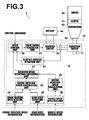
- Figure 3 is a schematic configuration diagram of a vehicle equipped with a retarder according to a second embodiment of the present invention
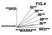
- Figure 4 is a graph illustrating the relationship between the engine rotation speed and the motor rotation speed.
- the configuration of the control unit 12 is changed in comparison with the first embodiment. Note that the elements identical to those of Figure 1 are given the same reference numerals and will not be elaborated upon further here unless otherwise specifically required, and only the difference is basically described here.
- the control unit 12 includes a speed control unit 20 that performs speed control of an induction motor 11 by receiving an operation control command from the vehicle 2 side (outside of the retarder 10'), a drive signal generation unit 21 that generates a drive signal for driving an inverter circuit 22, to be described later, based on an instruction from the speed control unit 20, the inverter circuit 22 for controlling the induction motor 11 and sending electric power generated by the induction motor 11 to the battery 44, and an electric current detection unit 23 that detects an amount of electric current flowing in and out of the induction motor 11.
- control unit 12 includes an engine rotation speed detection unit 24 that receives information detected by a rotation speed sensor for the engine 40 from the vehicle 2 side (outside of the retarder 10'), a gear state detection unit 25 that receives information indicating a gear state of the transmission 42 also from the vehicle 2 side (outside of the retarder 10'), a motor rotation speed calculation unit 26 that performs signal conversion to a form that allows the speed control unit 20 to correctly recognize the rotation speed of the induction motor 11 based on the information detected by the rotation speed sensor for the engine 40 and information indicating the gear state of the transmission 42, a vehicle speed detection unit 28 that receives information detected by a vehicle speed sensor for the vehicle 2 from the vehicle 2 side (outside of the retarder 10'), a motor rotation speed calculation unit 29 that performs signal conversion to a form that allows the speed control unit 20 to correctly recognize the rotation speed of the induction motor 11 based on the information (signal) detected by the vehicle speed sensor, and a rotation speed detection switching unit 27 that performs switching to send a rotation speed signal obtained by
- information received by the engine rotation speed detection unit 24, the gear state detection unit 25, and the vehicle speed detection unit 28 is a digital signal flowing through an in-vehicle digital communication system, such as CAN (Controlled Area Network) or the like, within the vehicle 2.
- CAN Controlled Area Network
- the engine rotation speed detection unit 24, the gear state detection unit 25, and the vehicle speed detection unit 28 are depicted independently in Figure 3 , but a configuration may be adopted in which the information detected by the rotation speed sensor for the engine 40, the information indicating the gear state of the transmission 42, and information detected by the vehicle speed sensor are received by the same signal receiving unit.
- the induction motor 11 may be controlled based also on the information detected by the vehicle speed sensor and, in this case, the induction motor 11 may be controlled by the processing easier than to derive the rotation speed of the induction motor 11 (i.e., rotation speed of the output shaft of the transmission 42) based on the information detected by the rotation speed sensor for the engine 40 and the information indicating the gear state of the transmission 42.
- Vehicle speed sensors which generally use rotation sensors, such as resolvers and the like, the speed detection accuracy is not so high in a low speed (low rotation) region and the induction motor may not be controlled accurately in the low speed region.
- the speed detection accuracy of the rotation speed sensor for the engine 40 which is a sensor identical to the vehicle speed sensor is not so high in the low speed region as in the vehicle speed sensor but, unless the speed reduction ratio of the transmission 42 falls below 1, the rotation speed of the rotation speed sensor for the engine 40 is higher than that of the vehicle speed sensor, so that higher speed detection accuracy may be obtained by deriving the rotation speed of the induction motor 11 based on the information detected by the rotation speed sensor for the engine 40 and the information indicating the gear state of the transmission 42 under such circumstances.
- the rotation speed detection switching unit 27 obtains information detected by the rotation speed sensor for the engine 40 and information indicating the gear state of the transmission 42, and performs switching such that the rotation speed signal obtained by the motor rotation speed calculation unit 26 (rotation speed signal based on the rotation speed of the engine 40 and the gear state) is sent to the speed control unit 20 if the gear is in the first speed stage and the rotation speed of the engine 40 is in the region lower than a predetermined rotation speed. In all the other states, the rotation speed detection switching unit 27 performs switching such that the rotation speed signal obtained by the motor rotation speed calculation unit 29 (rotation speed signal based on the vehicle speed sensor) is sent to the speed control unit 20.
- the switching may be performed such that the rotation speed signal obtained by the motor rotation speed calculation unit 26 (rotation speed signal based on the rotation speed of the engine 40 and the gear state) is sent to the speed control unit 20 not only in the first speed stage but also in all gear stages other than that in which the speed reduction ratio is less than 1 in the region where the rotation speed of the induction motor 11 is low and the accuracy of the rotation speed signal based on the vehicle speed sensor is not so high (the region below the dotted line in Figure 4 ).
- the speed control unit 20 Based on an operation control command from the vehicle 2 side (outside of the retarder 10'), the speed control unit 20 performs appropriate control of the induction motor 11 by adjusting the slippage of the induction motor 11 according to the characteristics of induction motor as shown in Figure 2 based on the rotation speed signal outputted from the rotation speed detection switching unit 27.
- the speed detection accuracy may be improved by the use of a method of controlling the induction motor 11 based on the information detected by the rotation speed sensor for the engine 40 and information indicating the gear state of the transmission 42 in the low speed (rotation speed) region where the speed detection accuracy is degraded, so that the induction motor 11 may be controlled efficiently.
- the information received from the vehicle 1, 2 (retarder 10, 10') as the information detected by the rotation speed sensor for the engine 40 or the information detected by the vehicle speed sensor is not limited to the digital signal described above and may be the output signal itself of each sensor (so-called a rotation pulse signal or vehicle speed pulse signal), and in that case, the received pulse signal may be converted to a signal that allows the speed control unit 20 to correctly recognize the rotation speed of the induction motor 11 in the motor rotation speed calculation unit 26, 29 and outputted. If the vehicle speed pulse signal is in an identical form to that of the signal that allows the speed control unit 20 to correctly recognize the rotation speed of the induction motor 11, the conversion is not required.
Landscapes
- Engineering & Computer Science (AREA)
- Transportation (AREA)
- Mechanical Engineering (AREA)
- Power Engineering (AREA)
- Chemical & Material Sciences (AREA)
- Combustion & Propulsion (AREA)
- Electric Propulsion And Braking For Vehicles (AREA)
- Hybrid Electric Vehicles (AREA)
- Control Of Eletrric Generators (AREA)
- Control Of Ac Motors In General (AREA)
Abstract
Description
- The present invention relates to a retarder used in a vehicle, and more particularly to a retarder equipped with an induction motor capable of performing brake application, electric power generation, and torque generation.
- Recently, in response to the demand for low fuel consumption of vehicles, the engines mounted on vehicles tend to be downsized. The downsizing of the engines reduces the effect of exhaust brake and engine brake, and necessitates the combined use of retarders for assisting in braking ability of vehicles.
- As for the retarders, eddy current systems and fluid systems are commonly known, but with respect to the eddy current retarders of these systems, conventional eddy current retarders have been neither able to generate electric power nor regenerate energy generated during braking so that they have not been unable to satisfy the recent demand for low energy consumption. Further, such retarders have not been able to produce driving torque by themselves for assisting in the engine output so that they have not been used as auxiliary power of vehicles.
- Therefore, in the eddy current retarders, retarders equipped with an induction motor capable of applying braking, generating electric power, and producing torque have recently been proposed (e.g.,
Patent Documents 1 and 2). - In torque control of the induction motor, it is important to control the relative speed which is the difference between the synchronous speed and the actual rotation speed, and the amount of "slip" which is a ratio with respect to the synchronous speed. Therefore, in the retarders of such induction motor systems, it is generally necessary to obtain the actual rotation speed of the induction motor for controlling the induction motor.
- Thus, it is necessary to mount a rotation speed sensor, such as a resolver or the like, on an induction motor. In mounting a rotation speed sensor on an induction motor, however, it is necessary to attach the rotation speed sensor to the high temperature rotor without being affected by the heat, thereby causing the structure of the entire motor to be complicated and giving rise to a problem of leading to cost increase, in addition to the cost of the rotation speed sensor itself.
-
- Patent Document 1: Japanese Unexamined Patent Publication No.
8 (1996)-126118 - Patent Document 2: Japanese Unexamined Patent Publication No.
10 (1998)-225096 - In order to reduce the cost of an induction motor, a sensor-less control that does not require a rotation speed sensor is proposed.
- The principle of the sensor-less control proposed in the past is to detect a deviation between the theoretical value and the actual value in induced electromotive force generated in the stator when the rotor is controlled so as to rotate at a predetermined rotation speed, and to estimate and control the rotation speed of the rotor by controlling the command value of rotation speed based on the amount of deviation.
- The method allows the control according to the principle if rotation control is performed from the state in which the rotor is stopped, but if the rotation control is performed from the state in which the rotor is rotating, the control according to the principle cannot be performed because the amount of deviation described above may become excessive depending on the operation state of the rotor at the time of control and stable control becomes difficult.
- The present invention has been developed in view of the circumstances described above, and it is an object of the present invention to provide, in retarders equipped with induction motors, a retarder capable of performing accurate sensor-less control regardless of the operation state of the motor.
- A retarder of the present invention is a retarder used in a vehicle in which an axle is driven by an internal combustion engine via a transmission, the retarder including an induction motor coupled to an output shaft of the transmission, and a control means that derives a rotation speed of the induction motor based on information detected by a rotation speed sensor for the internal combustion engine provided in the vehicle and information indicating a gear state of the transmission obtained from the vehicle, and controls the induction motor based on the derived rotation speed.
- In the retarder of the present invention, the transmission may be any type of transmission, such as MT (Manual Transmission), AT (Automatic Transmission), CVT (Continuously Variable Transmission), or the like.
- The "information detected by a rotation speed sensor for the internal combustion engine (engine)" may be any signal as long as it corresponds to the rotation speed of the engine, such as the output signal of the engine rotation speed sensor itself (e.g., a signal so-called a rotation pulse signal), a digital signal corresponding to the engine rotation speed flowing through an in-vehicle digital communication system, such as CAN (Controlled Area Network), or the like.
- Further, the "information indicating a gear state" may be any form of information as long as it eventually allows the speed reduction ratio of the transmission to be identified other than information of gear stage (including neutral). In a case where the control means obtains only the gear stage from the vehicle side, information of reduction rate at each gear stage needs to be obtained in advance.
- The phrase "derives a rotation speed of the induction motor based on information detected by a rotation speed sensor for the internal combustion engine and information indicating a gear state of the transmission obtained from the vehicle" refers to obtain information of speed which is proportional to the rotation speed of the output shaft of the transmission, for example, by diving the rotation speed of the internal combustion engine by the speed reduction ratio of the transmission or the like.
- In the retarder of the present invention, it is difficult to accurately derive the rotation speed of the induction motor under the state in which no driving force is conveyed between the internal combustion engine and the output shaft of the transmission, such as the case where a clutch provided in the vehicle is disconnected or the gear is in neutral. Therefore, the control means may be a means that, if a variation in rotation speed of the internal combustion engine per unit time exceeds a predetermined threshold value, i.e., if the rotation speed of the internal combustion engine is increased rapidly, puts the induction motor into uncontrolled state in which any control to the induction motor is stopped or controls the induction motor such that neither driving torque nor braking torque is generated, assuming that the clutch is being disconnected or the gear is being in neutral.
- Further, the control means may be a means that puts the induction motor into uncontrolled state in which any control to the induction motor is stopped or controls the induction motor such that neither driving torque nor braking torque is generated if information indicating disconnection of a clutch provided in the vehicle is obtained or if the gear of the transmission is in neutral.
- As vehicle speed sensors provided in vehicles are generally detect the rotation speed of the output shaft of the transmission, the induction motor may be controlled based also on the information detected by the vehicle speed sensor. In this case, the induction motor may be controlled by the processing easier than to derive the rotation speed of the induction motor (i.e., rotation speed of the output shaft of the transmission) based on the information detected by the rotation speed sensor for the internal combustion engine and the information indicating the gear state of the transmission.
- The vehicle speed sensors for which rotation detection sensors, such as tachogenerators and the like, are generally used, however, the speed detection accuracy is not so high in a low speed (low rotation) region and the induction motor may not be controlled accurately in the low speed region. The speed detection accuracy of the rotation speed sensor for the internal combustion engine which is a sensor identical to the vehicle speed sensor is not so high in the low speed region as in the vehicle speed sensor, but, unless the speed reduction ratio of the transmission falls below 1, the rotation speed of the rotation speed sensor for the internal combustion engine is higher than that of the vehicle speed sensor, so that higher speed detection accuracy may be obtained by deriving the rotation speed of the induction motor based on the information detected by the rotation speed sensor for the internal combustion engine and the information indicating the gear state of the transmission under such circumstances.
- Therefore, the control means may further include a function to control the induction motor based on information detected by a vehicle speed sensor provided in the vehicle, and the control means may be a means that performs switching, based on at least one of the information detected by the vehicle speed sensor and the information indicating a gear state of the transmission, whether to control the induction motor based on the information detected by the rotation speed sensor and the information indicating a gear state of the transmission or to control the induction motor based on the information detected by the vehicle speed sensor.
- The "information detected by a vehicle speed sensor provided in the vehicle" may be any signal as long as it corresponds to the vehicle speed, such as the output signal of the vehicle speed sensor itself (e.g., a signal so-called a vehicle speed pulse signal), a digital signal corresponding to the vehicle speed flowing through an in-vehicle digital communication system, such as CAN (Controlled Area Network), or the like.
- The phrase "control the induction motor based on the information detected by the vehicle speed sensor" refers to control the induction motor based on the information described above and if, for example, the induction motor is controlled based on the vehicle speed pulse signal, the control circuit (control means) of the retarder is configured to control the induction motor based on the output signal of the rotation speed sensor originally provided in the induction motor, such as a resolver, because the vehicle speed sensor generally detects the rotation speed of the output shaft of the transmission to which the induction motor is coupled, and if the output signal of the rotation speed sensor original provided in the induction motor is identical to the vehicle speed pulse signal, the received vehicle speed pulse signal may be deemed as the output signal of the rotation speed sensor and the existing control circuit of the induction motor may be used directly.
- Even in the case where the control circuit (control means) of the retarder is configured to control the induction motor based on the output signal of the rotation speed sensor originally provided in the induction motor, if the output signal of the rotation speed sensor originally provided in the induction motor and the vehicle speed pulse signal are different types of signals or if a digital signal corresponding to the vehicle speed flowing through the in-vehicle digital communication system, such as CAN (Controller Area Network), is received, the received signal needs to be converted so as to correspond to the signal indicating the rotation speed of the induction motor in the control circuit of the induction motor.
- In this case, therefore, the control means may be a means that derives a rotation speed of the induction motor based on the information detected by the vehicle speed sensor and controls the induction motor based on the derived rotation speed.
- A control method of the present invention is a method in a retarder used in a vehicle in which an axle is driven by an internal combustion engine via a transmission, the method controlling an induction motor coupled to an output shaft of the transmission, wherein the method derives a rotation speed of the induction motor based on information detected by a rotation speed sensor for the internal combustion engine provided in the vehicle and information indicating a gear state of the transmission obtained from the vehicle, and controls the induction motor based on the derived rotation speed.
- The control method of the present invention may put the induction motor into uncontrolled state in which any control to the induction motor is stopped or controls the induction motor such that neither driving torque nor braking torque is generated if a variation in rotation speed of the internal combustion engine per unit time exceeds a predetermined threshold value.
- Further, the control method may put the induction motor into uncontrolled state in which any control to the induction motor is stopped or controls the induction motor such that neither driving torque nor braking torque is generated if information indicating disconnection of a clutch provided in the vehicle is obtained or if the gear of the transmission is in neutral.
- Still further, the control method may further obtain information detected by a vehicle speed sensor provided in the vehicle and the method may perform switching, based on at least one of the information detected by the vehicle speed sensor and the information indicating a gear state of the transmission, whether to control the induction motor based on the information detected by the rotation speed sensor and the information indicating a gear state of the transmission or to control the induction motor based on the information detected by the vehicle speed sensor.
- In this case, the control method may derive a rotation speed of the induction motor based on the information detected by the vehicle speed sensor and control the induction motor based on the derived rotation speed.
- According to the retarder and control method of the present invention, a rotation speed of an induction motor is derived based on information detected by a rotation speed sensor for the internal combustion engine provided in the vehicle and information indicating a gear state of the transmission obtained from the vehicle, and the induction motor is controlled based on the derived rotation speed, thereby allowing the rotation speed of the induction motor to be obtained without mounting a rotation speed sensor on the induction motor. This allows accurate sensor-less control regardless of the operation state of the motor with low cost. Note that the retarder of the present invention may be applied to any type of vehicle regardless of the type of vehicle on which it is mounted.
- Further, if a variation in rotation speed of the internal combustion engine per unit time exceeds a predetermined threshold value, i.e., if the rotation speed of the internal combustion engine is increased rapidly, the retarder may be prevented from falling into a dangerous operating condition based on inaccurate information by putting the induction motor into uncontrolled state in which any control to the induction motor is stopped or controlled such that neither driving torque nor braking torque is generated, assuming that the clutch is being disconnected or the gear is being in neutral.
- Further, the identical effect to that of the foregoing may also be obtained if the induction motor is put into uncontrolled state in which any control to the induction motor is stopped or controlled such that neither driving torque nor braking torque is generated when information indicating disconnection of a clutch provided in the vehicle is obtained or when the gear of the transmission is in neutral.
- Still further, if information detected by a vehicle speed sensor provided in the vehicle is further obtained and switching is performed, based on at least one of the information detected by the vehicle speed sensor and the information indicating a gear state of the transmission, whether to control the induction motor based on the information detected by the rotation speed sensor and the information indicating a gear state of the transmission or to control the induction motor based on the information detected by the vehicle speed sensor, the speed detection accuracy may be improved by the use of a method of controlling the induction motor based on the information detected by the rotation speed sensor and information indicating the gear state of the transmission in the low speed (rotation speed) region where the speed detection accuracy is degraded, while controlling the induction motor using a method of controlling the induction motor based on the information which may be processed easily detected by the vehicle sensor, so that the induction motor may be controlled efficiently.
- In this case, if an arrangement is adopted in which a rotation speed of the induction motor is derived based on the information detected by the vehicle speed sensor and the induction motor is controlled based on the derived rotation speed, the induction motor maybe controlled accurately even when the form of the signal received from the vehicle side and the form of the signal indicating the rotation speed of the induction motor in the control circuit (control means) are different.
-
-
Figure 1 is a schematic configuration diagram of a vehicle equipped with a retarder according to a first embodiment of the present invention. -
Figure 2 is a graph illustrating the characteristics of an induction motor mounted on the retarder described above. -
Figure 3 is a schematic configuration diagram of a vehicle equipped with a retarder according to a second embodiment of the present invention. -
Figure 4 is a graph illustrating the relationship between the engine rotation speed and the motor rotation speed. - Hereinafter, a first embodiment of the retarder of the present invention will be described in detail with reference to the accompanying drawings.
Figure 1 is a schematic configuration diagram of a vehicle equipped with a retarder according to a first embodiment of the present invention andFigure 2 is a graph illustrating the characteristics of an induction motor mounted on the retarder described above. - A
vehicle 1 basically includes anengine 40 for driving the axle of the vehicle, atransmission 42 that performs conversion between the output rotation speed of theengine 40 and the torque by a combination of gears, a clutch for joining/separating connection between theengine 40 and thetransmission 42, aretarder 10 for applying braking or torque to the rotation of the main shaft of the engine 40 (output shaft of the transmission 42) or generating electric power by the rotation of the main shaft of theengine 40, abattery 44 for storing/supplying electric power, and the like. - The
retarder 10 of the present embodiment is capable of performing any of brake application, electric power generation, and torque generation, and includes aninduction motor 11 coupled to theoutput shaft 43 of thetransmission 42 and a control unit (control means) 12 for controlling theinduction motor 11. - The
control unit 12 includes aspeed control unit 20 that performs speed control of theinduction motor 11 by receiving an operation control command from thevehicle 1 side (outside of the retarder 10), a drivesignal generation unit 21 that generates a drive signal for driving aninverter circuit 22, to be described later, based on an instruction from thespeed control unit 20, theinverter circuit 22 for controlling theinduction motor 11 and sending electric power generated by theinduction motor 11 to thebattery 44, and an electriccurrent detection unit 23 that detects an amount of electric current flowing in and out of theinduction motor 11. - Further, the
control unit 12 includes an engine rotationspeed detection unit 24 that receives information detected by a rotation speed sensor for theengine 40 from thevehicle 1 side (outside of the retarder 10), a gearstate detection unit 25 that receives information indicating a gear state of the transmission 42 (in the present embodiment, information indicating a gear stage) also from thevehicle 1 side (outside of the retarder 10), a motor rotationspeed calculation unit 26 that performs signal conversion to a form that allows thespeed control unit 20 to correctly recognize the rotation speed of theinduction motor 11 based on the information detected by the rotation speed sensor for theengine 40 and information indicating the gear state of thetransmission 42, and a rotation speeddetection switching unit 27 that switches whether or not to send a rotation speed signal obtained by the motor rotationspeed calculation unit 26 to thespeed control unit 20. - As the rotor of the
induction motor 11 is coupled to theoutput shaft 43 of thetransmission 42 and the rotation speed of theinduction motor 11 is the same as that of theoutput shaft 43, the rotation speed of theinduction motor 11 may be obtained by calculating the rotation speed of theoutput shaft 43 based on the information detected by the rotation speed sensor for theengine 40 and the information indicating the gear state of thetransmission 42. - In the present embodiment, information received by the engine rotation
speed detection unit 24 and the gearstate detection unit 25 is a digital signal flowing through an in-vehicle digital communication system, such as CAN (Controlled Area Network) or the like, within thevehicle 1. - As a functional block diagram, the engine rotation
speed detection unit 24 and the gearstate detection unit 25 are depicted independently inFigure 1 , but a configuration may be adopted in which the information detected by the rotation speed sensor for theengine 40 and the information indicating the gear state of thetransmission 42 are received by the same signal receiving unit. - The motor rotation
speed calculation unit 26 has information of speed reduction ratio at each gear stage in advance, calculates a numerical value of the rotation speed of the output shaft of thetransmission 42 by dividing the rotation speed of theengine 40 by the current speed reduction ratio of thetransmission 42, then based on the numerical value, performs signal conversion to a form that allows thespeed control unit 20 to recognize the rotation speed of theinduction motor 11, and outputs the converted rotation speed signal to thespeed control unit 20. - Based on an operation control command from the
vehicle 1 side (outside of the retarder 10), thespeed control unit 20 performs appropriate control of theinduction motor 11 by adjusting the slip amount of theinduction motor 11 according to the characteristics of induction motor shown inFigure 2 based on the rotation speed signal outputted from the motor rotationspeed calculation unit 26. - The term "slip" as used herein refers to the ratio of the relative speed, which is the difference between the synchronous speed NS (rpm) and the actual rotation speed N (rpm), to the synchronous speed NS, and represented by a formula (1) given below:

- The
retarder 10 of the present embodiment is capable of performing any of brake application, electric power generation, and torque generation, and controls theinduction motor 11 such that the slip becomes greater than a value of 1 during braking. Further, it controls theinduction motor 11 such that the slip is greater than a value of 0 and smaller than a value of 1 during motor assisting (torque generation). - Further, it controls the
induction motor 11 such that the slip is smaller than a value of 0 during regenerative operation (electric power generation) . It is common that the slip is set close to 0 where the electric power generation amount is large (region where the value of regenerative electric power shown by the dash-dot line is small in the vertical axis direction inFigure 2 ) but, if the storage capacity of thebattery 44 becomes full during the regenerative operation, the regenerative operation cannot be continued. Therefore, if the storage capacity of thebattery 44 becomes full during the regenerative operation, the regenerative operation may be continued without interruption by increasing the slip in the negative direction and shifting to a region where electric power consumption exceeds the regenerative electric power (region where the value of regenerative electric power shown by the dash-dot line becomes plus in the vertical axis direction inFigure 2 ). - Such arrangement described above allows the rotation speed of the motor to be obtained without mounting a rotation speed sensor on the
induction motor 11 itself, whereby accurate sensor-less control is possible at low cost and regardless of the operation state of the motor. - If information of disconnection of a clutch 41 of the
vehicle 1 is obtained, or when the gear of thetransmission 42 is in neutral, or further if the rotation speed of theengine 40 is increased rapidly, theretarder 10 may be prevented from falling into a dangerous operating condition based on inaccurate information by putting theinduction motor 11 into uncontrolled state in which any control to the induction motor is stopped or controlling the induction motor such that neither driving torque nor braking torque is generated, assuming that the clutch is being disconnected or the gear is being in neutral. - Next, a second embodiment of the retarder of the present invention will be described in detail.
Figure 3 is a schematic configuration diagram of a vehicle equipped with a retarder according to a second embodiment of the present invention, andFigure 4 is a graph illustrating the relationship between the engine rotation speed and the motor rotation speed. In the present embodiment, the configuration of thecontrol unit 12 is changed in comparison with the first embodiment. Note that the elements identical to those ofFigure 1 are given the same reference numerals and will not be elaborated upon further here unless otherwise specifically required, and only the difference is basically described here. - The
control unit 12 includes aspeed control unit 20 that performs speed control of aninduction motor 11 by receiving an operation control command from thevehicle 2 side (outside of the retarder 10'), a drivesignal generation unit 21 that generates a drive signal for driving aninverter circuit 22, to be described later, based on an instruction from thespeed control unit 20, theinverter circuit 22 for controlling theinduction motor 11 and sending electric power generated by theinduction motor 11 to thebattery 44, and an electriccurrent detection unit 23 that detects an amount of electric current flowing in and out of theinduction motor 11. - Further, the control unit 12 includes an engine rotation speed detection unit 24 that receives information detected by a rotation speed sensor for the engine 40 from the vehicle 2 side (outside of the retarder 10'), a gear state detection unit 25 that receives information indicating a gear state of the transmission 42 also from the vehicle 2 side (outside of the retarder 10'), a motor rotation speed calculation unit 26 that performs signal conversion to a form that allows the speed control unit 20 to correctly recognize the rotation speed of the induction motor 11 based on the information detected by the rotation speed sensor for the engine 40 and information indicating the gear state of the transmission 42, a vehicle speed detection unit 28 that receives information detected by a vehicle speed sensor for the vehicle 2 from the vehicle 2 side (outside of the retarder 10'), a motor rotation speed calculation unit 29 that performs signal conversion to a form that allows the speed control unit 20 to correctly recognize the rotation speed of the induction motor 11 based on the information (signal) detected by the vehicle speed sensor, and a rotation speed detection switching unit 27 that performs switching to send a rotation speed signal obtained by the motor rotation speed calculation unit 26, to send a rotation speed signal obtained by the motor rotation speed calculation unit 29, or not to send any rotation speed signal to the speed control unit 20.
- In the present embodiment, information received by the engine rotation
speed detection unit 24, the gearstate detection unit 25, and the vehiclespeed detection unit 28 is a digital signal flowing through an in-vehicle digital communication system, such as CAN (Controlled Area Network) or the like, within thevehicle 2. - As a functional block diagram, the engine rotation
speed detection unit 24, the gearstate detection unit 25, and the vehiclespeed detection unit 28 are depicted independently inFigure 3 , but a configuration may be adopted in which the information detected by the rotation speed sensor for theengine 40, the information indicating the gear state of thetransmission 42, and information detected by the vehicle speed sensor are received by the same signal receiving unit. - As the vehicle speed sensor for the
vehicle 2 is a sensor which generally detects the rotation speed of the output shaft of thetransmission 42, theinduction motor 11 may be controlled based also on the information detected by the vehicle speed sensor and, in this case, theinduction motor 11 may be controlled by the processing easier than to derive the rotation speed of the induction motor 11 (i.e., rotation speed of the output shaft of the transmission 42) based on the information detected by the rotation speed sensor for theengine 40 and the information indicating the gear state of thetransmission 42. - Vehicle speed sensors which generally use rotation sensors, such as resolvers and the like, the speed detection accuracy is not so high in a low speed (low rotation) region and the induction motor may not be controlled accurately in the low speed region. The speed detection accuracy of the rotation speed sensor for the
engine 40 which is a sensor identical to the vehicle speed sensor is not so high in the low speed region as in the vehicle speed sensor but, unless the speed reduction ratio of thetransmission 42 falls below 1, the rotation speed of the rotation speed sensor for theengine 40 is higher than that of the vehicle speed sensor, so that higher speed detection accuracy may be obtained by deriving the rotation speed of theinduction motor 11 based on the information detected by the rotation speed sensor for theengine 40 and the information indicating the gear state of thetransmission 42 under such circumstances. - An example relationship between the engine rotation speed and the motor rotation speed is illustrated in the graph of
Figure 4 . As illustrated in the graph, the rotation speed of theengine 40 is high with respect to the rotation speed of the induction motor 11 (i. e., rotation speed of the output shaft of the transmission 42), in particular, while the gear is in the first speed stage. Therefore, the rotation speeddetection switching unit 27 obtains information detected by the rotation speed sensor for theengine 40 and information indicating the gear state of thetransmission 42, and performs switching such that the rotation speed signal obtained by the motor rotation speed calculation unit 26 (rotation speed signal based on the rotation speed of theengine 40 and the gear state) is sent to thespeed control unit 20 if the gear is in the first speed stage and the rotation speed of theengine 40 is in the region lower than a predetermined rotation speed. In all the other states, the rotation speeddetection switching unit 27 performs switching such that the rotation speed signal obtained by the motor rotation speed calculation unit 29 (rotation speed signal based on the vehicle speed sensor) is sent to thespeed control unit 20. - Note that, as the rotation speed sensor for the
engine 40 is higher than that of the vehicle speed sensor in all gear stages other than that in which the speed reduction ratio is less than 1, the switching may be performed such that the rotation speed signal obtained by the motor rotation speed calculation unit 26 (rotation speed signal based on the rotation speed of theengine 40 and the gear state) is sent to thespeed control unit 20 not only in the first speed stage but also in all gear stages other than that in which the speed reduction ratio is less than 1 in the region where the rotation speed of theinduction motor 11 is low and the accuracy of the rotation speed signal based on the vehicle speed sensor is not so high (the region below the dotted line inFigure 4 ). - Based on an operation control command from the
vehicle 2 side (outside of the retarder 10'), thespeed control unit 20 performs appropriate control of theinduction motor 11 by adjusting the slippage of theinduction motor 11 according to the characteristics of induction motor as shown inFigure 2 based on the rotation speed signal outputted from the rotation speeddetection switching unit 27. - Such arrangement described above allows identical effects to those of the first embodiment to be obtained. Further, while controlling the
induction motor 11 using a method of controlling theinduction motor 11 based on the easily processed information detected by the vehicle sensor, the speed detection accuracy may be improved by the use of a method of controlling theinduction motor 11 based on the information detected by the rotation speed sensor for theengine 40 and information indicating the gear state of thetransmission 42 in the low speed (rotation speed) region where the speed detection accuracy is degraded, so that theinduction motor 11 may be controlled efficiently. - So far, the preferred embodiments of the present invention have been described, but the present invention is not limited to the aforementioned embodiments.
- For example, in each of the first and the second embodiments, the information received from the
vehicle 1, 2 (retarder 10, 10') as the information detected by the rotation speed sensor for theengine 40 or the information detected by the vehicle speed sensor is not limited to the digital signal described above and may be the output signal itself of each sensor (so-called a rotation pulse signal or vehicle speed pulse signal), and in that case, the received pulse signal may be converted to a signal that allows thespeed control unit 20 to correctly recognize the rotation speed of theinduction motor 11 in the motor rotationspeed calculation unit speed control unit 20 to correctly recognize the rotation speed of theinduction motor 11, the conversion is not required. - It should be understood that various modifications and changes other than the foregoing may also be made without departing from the spirit of the present invention.
Claims (12)
- A retarder used in a vehicle in which an axle is driven by an internal combustion engine via a transmission, the retarder comprising:an induction motor coupled to an output shaft of the transmission; anda control means that derives a rotation speed of the induction motor based on information detected by a rotation speed sensor for the internal combustion engine provided in the vehicle and information indicating a gear state of the transmission obtained from the vehicle, and controls the induction motor based on the derived rotation speed.
- The retarder as claimed in claim 1, wherein the control means is a means that puts the induction motor into uncontrolled state in which any control to the induction motor is stopped or controls the induction motor such that neither driving torque nor braking torque is generated if a variation in rotation speed of the internal combustion engine per unit time exceeds a predetermined threshold value.
- The retarder as claimed in claim 1 or 2, wherein:the vehicle comprises a clutch between the internal combustion engine and the transmission; andthe control means is a means that puts the induction motor into uncontrolled state in which any control to the induction motor is stopped or controls the induction motor such that neither driving torque nor braking torque is generated if information indicating disconnection of the clutch is obtained.
- The retarder as claimed in any of claims 1 to 3, wherein the control means is a means that puts the induction motor into uncontrolled state in which any control to the induction motor is stopped or controls the induction motor such that neither driving torque nor braking torque is generated if the gear of the transmission is in neutral.
- The retarder as claimed in any of claims 1 to 4, wherein:the control means further includes a function to control the induction motor based on information detected by a vehicle speed sensor provided in the vehicle; andthe control means is a means that performs switching, based on at least one of the information detected by the vehicle speed sensor and the information indicating a gear state of the transmission, whether to control the induction motor based on the information detected by the rotation speed sensor and the information indicating a gear state of the transmission or to control the induction motor based on the information detected by the vehicle speed sensor.
- The retarder as claimed in claim 5, wherein the control means is a means that derives a rotation speed of the induction motor based on the information detected by the vehicle speed sensor and controls the induction motor based on the derived rotation speed.
- A control method in a retarder used in a vehicle in which an axle is driven by an internal combustion engine via a transmission, the method controlling an induction motor coupled to an output shaft of the transmission,
wherein the method derives a rotation speed of the induction motor based on information detected by a rotation speed sensor for the internal combustion engine provided in the vehicle and information indicating a gear state of the transmission obtained from the vehicle, and controls the induction motor based on the derived rotation speed. - The control method as claimed in claim 7, wherein the control method puts the induction motor into uncontrolled state in which any control to the induction motor is stopped or controls the induction motor such that neither driving torque nor braking torque is generated if a variation in rotation speed of the internal combustion engine per unit time exceeds a predetermined threshold value.
- The control method as claimed in claim 7 or 8, wherein the control method puts the induction motor into uncontrolled state in which any control to the induction motor is stopped or controls the induction motor such that neither driving torque nor braking torque is generated if information indicating disconnection of a clutch provided in the vehicle is obtained.
- The control method as claimed in any of claims 7 to 9, wherein the control method puts the induction motor into uncontrolled state in which any control to the induction motor is stopped or controls the induction motor such that neither driving torque nor braking torque is generated if the gear of the transmission is in neutral.
- The control method as claimed in any of claims 7 to 10, wherein:the method further obtains information detected by a vehicle speed sensor provided in the vehicle; andthe method performs switching, based on at least one of the information detected by the vehicle speed sensor and the information indicating a gear state of the transmission, whether to control the induction motor based on the information detected by the rotation speed sensor and the information indicating a gear state of the transmission or to control the induction motor based on the information detected by the vehicle speed sensor.
- The control method as claimed in claim 11, wherein the control method derives a rotation speed of the induction motor based on the information detected by the vehicle speed sensor and controls the induction motor based on the derived rotation speed.
Applications Claiming Priority (2)
| Application Number | Priority Date | Filing Date | Title |
|---|---|---|---|
| JP2012095472A JP5964641B2 (en) | 2012-04-19 | 2012-04-19 | Retarder |
| PCT/JP2013/002541 WO2013157239A1 (en) | 2012-04-19 | 2013-04-15 | Retarder |
Publications (2)
| Publication Number | Publication Date |
|---|---|
| EP2840704A1 true EP2840704A1 (en) | 2015-02-25 |
| EP2840704A4 EP2840704A4 (en) | 2016-06-01 |
Family
ID=49383210
Family Applications (1)
| Application Number | Title | Priority Date | Filing Date |
|---|---|---|---|
| EP13777862.7A Withdrawn EP2840704A4 (en) | 2012-04-19 | 2013-04-15 | Retarder |
Country Status (4)
| Country | Link |
|---|---|
| EP (1) | EP2840704A4 (en) |
| JP (1) | JP5964641B2 (en) |
| KR (1) | KR20150004811A (en) |
| WO (1) | WO2013157239A1 (en) |
Families Citing this family (2)
| Publication number | Priority date | Publication date | Assignee | Title |
|---|---|---|---|---|
| KR101671975B1 (en) * | 2014-04-16 | 2016-11-03 | 가부시키가이샤 티비케이 | Resonant motor system |
| JP6068560B2 (en) * | 2015-06-03 | 2017-01-25 | 株式会社シマノ | Bicycle control device |
Family Cites Families (23)
| Publication number | Priority date | Publication date | Assignee | Title |
|---|---|---|---|---|
| JPH08126118A (en) * | 1987-02-18 | 1996-05-17 | Hino Motors Ltd | Electric braking device |
| JP2579828B2 (en) * | 1990-05-18 | 1997-02-12 | 日野自動車工業株式会社 | Electric braking and auxiliary accelerators for vehicles |
| JP2561554B2 (en) * | 1990-05-31 | 1996-12-11 | 日野自動車工業株式会社 | Electric braking and auxiliary accelerators for vehicles |
| JPH04328024A (en) * | 1991-04-26 | 1992-11-17 | Hino Motors Ltd | Auxiliary braking acceleration device of automobile |
| JPH0968064A (en) * | 1995-08-31 | 1997-03-11 | Hino Motors Ltd | Automatic stopping starting device of engine |
| JP3607960B2 (en) * | 1996-02-14 | 2005-01-05 | トヨタ自動車株式会社 | Motor control device and control method |
| JPH1022509A (en) | 1996-06-28 | 1998-01-23 | Omron Corp | Sensor device |
| EP1759915A3 (en) * | 1998-07-21 | 2007-03-14 | TOKYO R&D CO., LTD. | Hybrid vehicle and method of controlling its running |
| JP3542932B2 (en) * | 1999-08-04 | 2004-07-14 | 本田技研工業株式会社 | Method and apparatus for judging permission of deceleration regeneration / charging of hybrid vehicle |
| JP3824821B2 (en) * | 1999-10-08 | 2006-09-20 | 本田技研工業株式会社 | Regenerative control device for hybrid vehicle |
| JP3656242B2 (en) * | 1999-10-26 | 2005-06-08 | スズキ株式会社 | Vehicle motor control device |
| ATE300445T1 (en) * | 2000-02-02 | 2005-08-15 | Pacific Scient Electro Kinetic | INTEGRATED RETARDER AND ACCESSORIES |
| JP3485905B2 (en) * | 2001-04-26 | 2004-01-13 | 本田技研工業株式会社 | Motor control device |
| US6750626B2 (en) * | 2002-09-11 | 2004-06-15 | Ford Global Technologies, Llc | Diagnostic strategy for an electric motor using sensorless control and a position sensor |
| JP3777165B2 (en) * | 2003-02-25 | 2006-05-24 | 日野自動車株式会社 | Hybrid car |
| JP4230276B2 (en) * | 2003-05-19 | 2009-02-25 | 本田技研工業株式会社 | Brushless DC motor control device |
| JP4609069B2 (en) * | 2004-12-27 | 2011-01-12 | 日産自動車株式会社 | Electric vehicle charge / discharge control device |
| JP4192992B2 (en) * | 2007-02-15 | 2008-12-10 | トヨタ自動車株式会社 | Power output device and hybrid vehicle equipped with the power output device |
| JP5131051B2 (en) * | 2008-06-23 | 2013-01-30 | 株式会社デンソー | Rotating machine control device and rotating machine control system |
| JP5126080B2 (en) * | 2009-01-13 | 2013-01-23 | 株式会社デンソー | Start / stop control device for internal combustion engine and control device for rotating machine |
| JP5412845B2 (en) * | 2009-01-23 | 2014-02-12 | 日産自動車株式会社 | Vehicle motor control apparatus and method |
| JP5240004B2 (en) * | 2009-03-30 | 2013-07-17 | アイシン精機株式会社 | Vehicle control device |
| US8535201B2 (en) * | 2010-09-30 | 2013-09-17 | Ford Global Technologies, Llc | Method and strategy to detect the lock-up of planetary gear in power split hybrid vehicles |
-
2012
- 2012-04-19 JP JP2012095472A patent/JP5964641B2/en active Active
-
2013
- 2013-04-15 KR KR1020147029658A patent/KR20150004811A/en not_active Ceased
- 2013-04-15 WO PCT/JP2013/002541 patent/WO2013157239A1/en not_active Ceased
- 2013-04-15 EP EP13777862.7A patent/EP2840704A4/en not_active Withdrawn
Also Published As
| Publication number | Publication date |
|---|---|
| KR20150004811A (en) | 2015-01-13 |
| WO2013157239A1 (en) | 2013-10-24 |
| EP2840704A4 (en) | 2016-06-01 |
| JP5964641B2 (en) | 2016-08-03 |
| JP2013223399A (en) | 2013-10-28 |
Similar Documents
| Publication | Publication Date | Title |
|---|---|---|
| EP1798099B1 (en) | Control apparatus for electric motor and abnormality detection method for electric motor control | |
| US8307927B2 (en) | Rotating electrical machine control system and vehicle drive system including rotating electrical machine control system | |
| US9707860B2 (en) | Vehicle control device and vehicle control method | |
| EP2873576B1 (en) | Hybrid vehicle control device and hybrid vehicle control method | |
| CN104290756B (en) | Method and apparatus for the failure mitigation in the torque machine of power assembly system | |
| JP2012222856A (en) | Motor drive control method in electric vehicle | |
| US9428079B2 (en) | Electric vehicle | |
| US20130278195A1 (en) | Control apparatus of rotating electrical machine | |
| CN110466499B (en) | Method and system for driving hybrid vehicle | |
| CN112654541A (en) | Engine start control device for hybrid vehicle and hybrid vehicle | |
| JP5163707B2 (en) | Control device for hybrid vehicle | |
| US9738273B2 (en) | Vehicle control apparatus | |
| EP2840704A1 (en) | Retarder | |
| WO2014157183A1 (en) | Error detection device for hybrid vehicles and error detection method | |
| EP3272603B1 (en) | Control device and control method for hybrid vehicle | |
| WO2007107091A1 (en) | Gearshift power compensator | |
| JP2011172324A (en) | Inverter controller | |
| JP2009202710A (en) | Vehicle behavior control device and method thereof | |
| JP4419996B2 (en) | Slip determination device and slip determination method | |
| US20200331335A1 (en) | Synchronous machine drive control device, and vehicle equipped with synchronous machine subjected to drive control by said synchronous machine drive control device | |
| JP3620137B2 (en) | Auxiliary drive apparatus and drive method for electric vehicle | |
| KR102555514B1 (en) | Motor control apparatus in parallel hybrid vehicle and method for diagnosing motor failure thereof | |
| JP4325610B2 (en) | Drive device for hybrid vehicle | |
| JPH0998519A (en) | Electric vehicle drive | |
| KR20120104672A (en) | Unit for driving oil pump for plug-in hybrid vehicle and method thereof |
Legal Events
| Date | Code | Title | Description |
|---|---|---|---|
| PUAI | Public reference made under article 153(3) epc to a published international application that has entered the european phase |
Free format text: ORIGINAL CODE: 0009012 |
|
| 17P | Request for examination filed |
Effective date: 20141106 |
|
| AK | Designated contracting states |
Kind code of ref document: A1 Designated state(s): AL AT BE BG CH CY CZ DE DK EE ES FI FR GB GR HR HU IE IS IT LI LT LU LV MC MK MT NL NO PL PT RO RS SE SI SK SM TR |
|
| AX | Request for extension of the european patent |
Extension state: BA ME |
|
| DAX | Request for extension of the european patent (deleted) | ||
| RA4 | Supplementary search report drawn up and despatched (corrected) |
Effective date: 20160429 |
|
| RIC1 | Information provided on ipc code assigned before grant |
Ipc: B60L 11/14 20060101ALI20160422BHEP Ipc: B60L 7/14 20060101ALI20160422BHEP Ipc: B60L 15/20 20060101ALI20160422BHEP Ipc: B60K 6/48 20071001ALI20160422BHEP Ipc: H02P 23/00 20160101ALI20160422BHEP Ipc: H02P 15/00 20060101AFI20160422BHEP |
|
| STAA | Information on the status of an ep patent application or granted ep patent |
Free format text: STATUS: THE APPLICATION IS DEEMED TO BE WITHDRAWN |
|
| 18D | Application deemed to be withdrawn |
Effective date: 20161129 |