EP2840412A1 - System und Verfahren zur Ausleuchtung und Abbildung eines Objekts - Google Patents
System und Verfahren zur Ausleuchtung und Abbildung eines Objekts Download PDFInfo
- Publication number
- EP2840412A1 EP2840412A1 EP13196029.6A EP13196029A EP2840412A1 EP 2840412 A1 EP2840412 A1 EP 2840412A1 EP 13196029 A EP13196029 A EP 13196029A EP 2840412 A1 EP2840412 A1 EP 2840412A1
- Authority
- EP
- European Patent Office
- Prior art keywords
- radiation
- polarization
- reflector element
- antenna
- reflected
- Prior art date
- Legal status (The legal status is an assumption and is not a legal conclusion. Google has not performed a legal analysis and makes no representation as to the accuracy of the status listed.)
- Granted
Links
Images




Classifications
-
- G—PHYSICS
- G01—MEASURING; TESTING
- G01S—RADIO DIRECTION-FINDING; RADIO NAVIGATION; DETERMINING DISTANCE OR VELOCITY BY USE OF RADIO WAVES; LOCATING OR PRESENCE-DETECTING BY USE OF THE REFLECTION OR RERADIATION OF RADIO WAVES; ANALOGOUS ARRANGEMENTS USING OTHER WAVES
- G01S7/00—Details of systems according to groups G01S13/00, G01S15/00, G01S17/00
- G01S7/02—Details of systems according to groups G01S13/00, G01S15/00, G01S17/00 of systems according to group G01S13/00
- G01S7/024—Details of systems according to groups G01S13/00, G01S15/00, G01S17/00 of systems according to group G01S13/00 using polarisation effects
-
- G—PHYSICS
- G01—MEASURING; TESTING
- G01S—RADIO DIRECTION-FINDING; RADIO NAVIGATION; DETERMINING DISTANCE OR VELOCITY BY USE OF RADIO WAVES; LOCATING OR PRESENCE-DETECTING BY USE OF THE REFLECTION OR RERADIATION OF RADIO WAVES; ANALOGOUS ARRANGEMENTS USING OTHER WAVES
- G01S13/00—Systems using the reflection or reradiation of radio waves, e.g. radar systems; Analogous systems using reflection or reradiation of waves whose nature or wavelength is irrelevant or unspecified
- G01S13/88—Radar or analogous systems specially adapted for specific applications
- G01S13/887—Radar or analogous systems specially adapted for specific applications for detection of concealed objects, e.g. contraband or weapons
-
- G—PHYSICS
- G01—MEASURING; TESTING
- G01S—RADIO DIRECTION-FINDING; RADIO NAVIGATION; DETERMINING DISTANCE OR VELOCITY BY USE OF RADIO WAVES; LOCATING OR PRESENCE-DETECTING BY USE OF THE REFLECTION OR RERADIATION OF RADIO WAVES; ANALOGOUS ARRANGEMENTS USING OTHER WAVES
- G01S13/00—Systems using the reflection or reradiation of radio waves, e.g. radar systems; Analogous systems using reflection or reradiation of waves whose nature or wavelength is irrelevant or unspecified
- G01S13/02—Systems using reflection of radio waves, e.g. primary radar systems; Analogous systems
- G01S13/06—Systems determining position data of a target
- G01S13/46—Indirect determination of position data
- G01S2013/462—Indirect determination of position data using multipath signals
Definitions
- the present invention relates to a system for illuminating and imaging objects by means of electromagnetic radiation, for example. Millimeter radiation, and an operating method for such a system.
- Microwaves in particular millimeter waves, are increasingly becoming u.a. used for personal scanner.
- Millimeter waves are suitable for the detection of metallic as well as non-metallic objects, for example ceramic objects such as knives.
- air and other materials such as those used for clothing are transparent to such radiation.
- millimeter-waves for non-contact scanners can be used for detection under the clothing of hidden objects.
- Such scanners are superior to metal detectors and can supplement or replace them, for example in the area of security controls at airports or security-related public facilities.
- a microwave signal of a given bandwidth is generated and emitted by at least one antenna in the direction of a human body with possibly hidden under the clothing objects.
- the microwave signals are reflected by the body and the hidden objects.
- a scanner may also include a plurality of transmitting and / or receiving antennas.
- Such a scanner can be operated, for example, in a multistatic mode, in a transmitter antenna emits a signal, and reflections of this signal according to amplitude and phase of several or all receiving antennas are received.
- multiple transmit antennas may transmit simultaneously, with the reflected signal of each transmit antenna being received by a plurality of receive antennas, respectively.
- Methods of aperture synthesis may be used, for example, digital beamforming (DBF) techniques which include focusing the emitted and / or received radiation for object scanning without mechanical movement of the antennas and without electromagnetic focusing by lenses or Like. Can take place; instead, focusing takes place only by targeted control of the transmitting antennas and / or evaluation of the signals detected by the receiving antennas. In the case of the latter, for example, a software-based algorithm evaluates a signal reflected from a given point in space in the direction of a plurality of antennas and received there.
- DBF digital beamforming
- DE 10 2011 078 539 A1 describes a device for illuminating a test object, wherein the device comprises at least one reflector element for reflecting microwave signals. In addition to the beams radiated directly onto the object and reflected by it, further microwave signals passing over the reflector element are received and used to reconstruct the image of the test object. Synthetic focusing is based on the idea of one or more virtual transmitting or receiving antennas whose positions correspond to the real positions of real transmitting or receiving antennas mirrored on a mirror axis.
- the reflector element allows for improved illumination of object areas that are illuminated by directly emitted signals too little or not at all. However, the mirroring of the object caused by the reflector element can lead to disturbances in the reconstruction, ie the imaging of the object.
- An object of the present invention is to propose a system and a method for imaging an object, in which disturbances in the reconstruction caused by a reflection element can be minimized, and thus both an improved illumination and an improved imaging quality can be achieved.
- a system for imaging an object which comprises at least one transmitting antenna for emitting electromagnetic radiation of a first polarization state for illuminating the object.
- At least one receiving antenna is provided for receiving radiation reflected by the object of a second polarization state.
- At least one reflector element is used for reflection of radiation emitted by the transmission antenna in the direction of the object and / or for reflection of radiation reflected by the object in the direction of the reception antenna.
- a polarization-effective material layer is provided on the reflector element in order to convert a radiation component reflected by the reflector element into a polarization state in such a way that the Radiation component at the receiving antenna in the second polarization state is.
- a processing unit is for determining the image of the object based on the radiation received by the receiving antenna.
- the system may be designed to illuminate and depict an object, such as a human or even an animal or inanimate object.
- Certain embodiments of the system have the purpose of detecting objects hidden on a person's body under their clothing which may include non-metallic objects such as ceramic weapons or sculpted plastic explosives objects.
- the transmitting and / or receiving antennas may, for example, be horn antennas.
- the electromagnetic radiation may comprise microwaves, for example radiation in the wavelength range from 1 millimeter to 10 millimeters.
- the first polarization state of the emitted radiation and the second polarization state of the received radiation may coincide or may be different, i. the transmitting and receiving antennas can be designed to emit or receive radiation of the same polarization state, or the receiving antenna is designed to receive radiation of a polarization state which differs from the polarization state of the emitted radiation.
- a polarization state can also relate to the emission or reception of unpolarized radiation.
- both the first polarization state and the second polarization state are concerned in each case a linear polarization, ie the transmitting antenna is designed to emit linearly polarized radiation, and the receiving antenna is designed to receive linearly polarized radiation.
- the transmitting antenna may be designed to emit linearly polarized radiation of a first vibration direction
- the receiving antenna may be configured to receive linearly polarized radiation of a second vibration direction.
- the first and second directions of vibration may be the same, or may be different, and may, for example, be tilted from each other by 80 ° to 100 °, preferably 90 °.
- the reflector element may have a flat or curved reflective surface.
- the reflector element can be made of a reflective metallic material.
- the polarization-effective material layer may comprise a coating, overlay, plate, disc, foil, coating, plating or deposition on the reflector element.
- the material layer may be operative to transform a linear polarization of incident radiation into an elliptical polarization of the reflected radiation.
- an elliptical polarization should also include the special case of a circular polarization.
- the polarization-effective material layer may also be designed to transform a linear polarization into another linear polarization, or to cause a reflection at the reflector element such that a linear polarization is maintained, ie a direction of oscillation of the incident and emergent radiation remains unchanged.
- the material of the layer may comprise a dielectric.
- the coating may preferably comprise polyethylene terephthalate (PET), polyvinyl chloride (PVC), polycarbonate (PC), glass, acrylic, and / or rubber; however, this listing is not exhaustive and, alternatively or additionally, other dielectrically active and / or insulating materials may be used.
- Embodiments of polarization-effective coatings or coatings may include, for example, grating or equivalent arrangements, such as laminations or coatings with electromagnetically active particles, such as nanoparticles.
- one of two provided reflector elements may be provided with a coating which introduces a polarization in a radiation, and the other reflector element may act on an existing polarization, for example by transforming a linear into an elliptical polarization.
- a thickness of the material layer may be selected to be less than a quarter of a wavelength of the electromagnetic radiation.
- the thickness may be chosen to be greater than one quarter of the wavelength, but should be outside a range of one quarter of the wavelength at which incident radiation is undesirably strongly absorbed.
- the thickness may suitably be less than one quarter of the wavelength, or more than one quarter of the wavelength but less than half the wavelength, and so on.
- Disturbances in the reconstruction of the object can u. U. also by a suitable adjustment of the reception level the reflections at the receiving antenna are minimized. Material and / or thickness of the coating material can therefore also be selected for general reflection or absorption capacity in the relevant wavelength range.
- a relative permittivity of the material of the layer may be between 2 and 4, preferably between 2.5 and 3.5. In alternative embodiments, a relative permittivity number of the layer material is chosen to be greater than 5, preferably greater than or equal to 6.
- the material layer is formed in such a way that a radiation fraction which is simply reflected by the reflector element is preferably detected at the receiving antenna. Additionally or alternatively, the reception of other radiation components on the receiving antenna can be suppressed, for example by multipath components of the radiation, which are reflected twice on the reflector element.
- the material layer is polarization-effective such that a superimposition of the simply reflected radiation component and a radiation component reflected twice by the reflector element is detected at the receiving antenna.
- Both components can, for example, be polarized in such a way that they couple approximately equally strongly to the receiving antenna.
- the system may include a plurality of transmitting and / or receiving antennas in a monostatic, bistatic or multistatic constellation.
- the processing unit may be designed to perform a transmitter-side and / or receiver-side synthetic focusing.
- a method for imaging an object comprising the following steps: emitting electromagnetic radiation of a first polarization state for illuminating the object; Reflection of at least one reflector element, radiation emitted by the transmitting antenna in the direction of the object and / or radiation reflected by the object in the direction of the receiving antenna, wherein a polarization-effective material layer on the reflector element, a reflected from the reflector element radiation component is converted into a polarization state such that the radiation component at the receiving antenna is in the second polarization state; Receiving from the object reflected radiation of a second polarization state; and determining the image of the object based on the radiation received by the receiving antenna.
- a known imaging system with uncoated reflector element only a special case in which certain mirror images are preferably detectable, while others are suppressed.
- the polarity-effective coating provided according to the invention, it is possible to influence which of the mirror images generated by the reflector element are detected by the receiving antennas and in which strength; this also includes desired superpositions of mirror images. This gives the person skilled in the art additional configuration options in order to optimize both the illumination and the imaging quality of a specific system.
- the illumination in peripheral areas of a detector can be improved, for example in the foot or floor area of personal scanners, whereby disturbances in the reconstruction can be minimized.
- the range of application of reflector elements for improved illumination of objects is extended; For example, additional reflector elements can be added to existing configurations to further improve illumination.
- a coating according to the invention can be realized in a simple manner by applying or bonding layers, films, mats or plates of commercially available materials such as PVC or glass on a metallic reflector example element cost. If an activation of the transmit antennas and / or evaluation of the received signals should be adapted, this usually requires only changes to a software, so that in addition to the provision of coated reflector plates, for example a coated floor plate, no further changes to a hardware constellation are required. An upgrade of existing systems is thus easily possible by providing an existing reflector with a coating or by a coated reflector is replaced, and if necessary, a software update is made.
- FIG. 1 an embodiment of an imaging system 100 according to the invention is shown schematically.
- the system 100 includes a vertical frame 102 in which a plurality of transmit antennas 104 and receive antennas 106 are disposed.
- the receiving antennas 104 are configured to irradiate linearly polarized microwaves into a region 108 in front of the frame 102 in order to illuminate an object located there, for example a person.
- the receiving antennas 106 serve to receive radiation reflected by the object and are designed to receive linearly polarized radiation.
- a processing unit 110 serves to drive the antennas 104, 106 and to determine an image of the object based on signals which represent the radiation received by the receiving antennas 106.
- the processing unit 110 may be designed for transmitter and / or receiver synthetic focussing.
- the antennas 104, 106 can be operated, for example, in a multistatic configuration.
- a bottom plate 112 with a reflector element 114 On the floor in front of the frame 102 is a bottom plate 112 with a reflector element 114. Plate 112 and element 114 are at an angle of 90 ° to the frame 102 with the antennas 104, 106 and define the illumination area 108, in this example downwards. Microwaves emitted by the transmit antennas 104 are reflected by the reflector element 114 toward the object. In addition, radiation reflected from the object is reflected toward the receiving antennas 106.
- the element 114 may comprise, for example, a metallic reflecting plate on which a person to be illuminated stands in an area indicated by the symbol 116.
- a polarization-effective coating 118 is applied on the reflector element 114, i. on its side facing the illumination area 108. This serves to convert a radiation component reflected by the reflector element 114 into a polarization state such that this radiation component is detected at the receiver antennas 106 because its polarization state coincides with the linear polarization of the antennas 106.
- the coating 118 transforms incident linearly polarized radiation into elliptically polarized radiation.
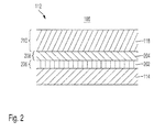
- Fig. 2 is a schematic sectional view of the bottom plate 112 with reflector element 114 and coating 118.
- the element 114 may, for example, be designed as a reflective metal plate, wherein the metal may be about aluminum.
- the metallic layer 112 may be sufficiently thick to be suitable, for example, for use as or in a bottom plate 112. Additionally or alternatively, the reflector element 112 may be mechanically stabilized by further layers or plates (not shown) which are attached to the reflector element 112 on the side facing away from the illumination region 108.
- a resist layer 202 may be applied to the reflector element 112.
- the layer 202 may serve to protect the reflector element 112 from mechanical and / or chemical stress and may, for example, comprise a clearcoat. at In other embodiments, a protective or lacquer layer can also be omitted.
- an adhesive layer 204 is applied, which serves the mechanical attachment of the overlying coating 118 on the reflector element 114 and the bottom plate 112.
- the material of the adhesive layer 204 should be selected depending on the materials of the adjacent layers 118 and 202 and 112, respectively, as well as the desired manufacturing process; For example, a hot melt adhesive may be used for a heat bonding process for adhering the coating 114 to the reflector element 112.
- An attachment of the coating 114 on the reflector element can be done differently instead of by gluing, for example.
- a mechanical attachment by means of clips, screws or rivets can be done.
- the reflector element is part of a base plate, a polarization-effective layer, plate or support can in the simplest case also be placed on the reflector element without further attachment; For example, reflector element and support can be held by a common frame.
- the adhesive layer 204 as well as the lacquer layer 202 may be omitted in other embodiments.
- one or more layers such as a resist layer comparable to layer 202, an adhesive layer comparable to layer 204, and / or other or other layers, these may contribute to the polarization efficiency of coating 118.
- layers such as layers 202 and 204 are for coating 118 attributable. In the following, for reasons of clarity, this aspect is not explicitly mentioned each time.
- the polarization-effective coating 118 may comprise a dielectric material.
- the coating 118 may be made of, for example, a material such as glass or a vitreous material including polycarbonate (PC), polymethyl methacrylate (PMMA) or acrylic or plexiglass, polyethylene terephthalate (PET), or other plastic glasses. Additionally or alternatively, the material of the coating 118 may also comprise other polarization-effective materials, such as, for example, polyethylene terephthalate (EPT), polyvinyl chloride (PVC) or rubber, for example polyacrylic rubber and / or C1 rubber. Also usable are materials with adjustable or controllable permittivity, which contain, for example, liquid crystals.
- a thickness 206 of the lacquer layer 202 may be between 10 microns and 70 microns, preferably between 10 microns and 60 microns, more preferably between 10 microns and 50 microns.
- a thickness 208 of the adhesive layer 204 may be between 10 microns and 70 microns, preferably between 10 microns and 60 microns, more preferably between 10 microns and 50 microns.
- the thicknesses 206 and 208 should each be as thin as possible.
- a polarization efficiency of the layers 202 and / or 204 is well known and can contribute to a desired polarization efficiency, this can be considered for the overall polarization efficiency.
- embodiments are conceivable in which is applied to a reflector element only one layer, for example, both serves as protection (protective lacquer) as well as polarization in the desired manner.
- a thickness 210 of the coating 118 is to be chosen depending on the desired polarization efficiency.
- the (effective) radiation thickness 210 may be designed to be less than one quarter of a wavelength of the radiation used, with respect to a dielectric permittivity of a dielectric, if used for the coating 118.
- frequencies of the radiation used in the range of 30 gigahertz to 100 gigahertz, preferably in the range of 70 gigahertz to 80 gigahertz resulting wavelengths of about 10 millimeters to 3 millimeters, preferably about 3.7 millimeters to 4.3 millimeters.
- the coating material selected is, for example, acrylic glass with a relative permittivity of 2.8
- a thickness 210 between 250 micrometers and 600 micrometers, preferably 300 micrometers and 400 micrometers can be selected.
- the thickness 210 of the acrylic glass used may be selected to be 350 microns.
- an effective relative permittivity of about 3.1 can be established for a lacquer layer 202 with a thickness 206 of 50 micrometers and an adhesive layer 204 with a thickness 208 of 50 micrometers; the detailed value depends on the optical properties of the paint and adhesive layers.
- a thickness 210 of this layer 118 may be between 200 micrometers and 500 microns, preferably 200 microns and 300 microns. In a particular embodiment, the thickness 210 of the PVC layer 118 used may be selected to be 220 microns.
- FIGS. 3A-3D schematically show possible different paths of rays from an antenna element 120 of the system 100 Fig. 1 in the direction of an object 302.
- multipath signals are generated, ie different mirror images occur at the location of the antenna element 120.
- the element 120 includes a plurality of transmit antennas 104 and a plurality of receive antennas 106.
- the transmit antennas 104 may be stacked in a vertical pattern 122 and the receive antennas 106 disposed in a separate horizontal pattern 124.
- Such an arrangement will be hereinafter referred to for the sake of explanation.
- transmitting and receiving antennas can also be arranged in other, also overlapping, patterns, for example alternately in a common pattern.
- Fig. 3A illustrates a direct path 304 of radiation emitted by the antenna element 120, more particularly the structure 122.
- the radiation impinges on the object 302 and passes directly back to the antenna element 120, ie without reflection at the reflector element 114, where it can be detected by the receiving antennas of the structure 124.
- Fig. 3B illustrates a simple reflection of the object 302 by the reflector element 114, namely a reflection of the received signal. Radiation emitted on the path 304 is reflected at the object 302 in the direction of the reflector element 114, is reflected at the reflector element 114 and thus reaches the receiving structures 124 on the path 306, 308.
- This is equivalent to a virtual path 306, 310, in which the reflector element or the mirror 114 is omitted and the radiation reflected by the object 302 passes on the path 306, 310 to virtual receiving structures 312, which are located below the reflector element 114 or the associated bottom plate.
- the position of the receiving structures 312 corresponds to that of the receiving structures 124, but mirrored on a mirror axis which lies in the plane of the reflector plate 114.
- Fig. 3C illustrates a further simple reflection of the object 302 by the reflector element 114, namely a reflection of the transmission signal. Radiation emitted on the path 308 is reflected at the reflector element 114 in the direction of the object 302, is reflected again at the object 302, and thus reaches the receiving structures 106 on the path 304. This is equivalent to a virtual path 310, 306 in which radiation falls from a virtual transmission structure 314 below the reflector element 118 on the object 302 and from there in the direction of the real receiving structure 106 passes.
- FIG. 2 illustrates a twofold reflection of the object 302 by the reflector element 114.
- radiation emitted on the path 308 is reflected by the reflector element 114 in the direction of the object 302.
- the radiation is reflected back to the reflector element 114 and reflected there in the direction of the receiving structures 106.
- This is equivalent to a virtual path 310, 306, 306, 310, in which radiation from the virtual transmission structure 314 below the reflector element 118 falls on the object 302 and from there goes back towards the virtual reception structure 312.
- the in the Figs. 3B and 3C illustrated simple reflection causes a gapless enlargement of the effectively illuminated aperture in the direction of the mirror surface, ie in the example of Fig. 1 Under the floor or the bottom plate 112.
- the illumination of objects or object areas can be improved, which extend substantially parallel to the antenna or sensor array, ie approximately parallel to the frame 102 in Fig. 1 .
- the reflector element, ie the mirror surface must extend in a suitable manner between the antenna assembly and the frame.
- illumination of the lower leg, including any objects present there may improve when the person is standing on (or immediately behind) a metallic floor panel and, for example, on the icon 116 of the system 100 in FIG Fig. 1 stands.
- Fig. 3D illustrated dual mirroring causes an improvement in the detection of highly tilted with respect to the plane of the antenna array objects. This includes the initial or improved detection of edges.
- the multi-path signal can be controlled, ie it can be a desired combination of simple and double reflections with an optimized for the specific application illumination with minimal disturbances in the reconstruction brought about. This is achieved via a polarization-effective coating according to the invention on the reflector element.
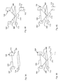
- FIG. 12 again schematically illustrates a path of radiation emitted by a transmit antenna 402 over a path 404 toward an object 406. From the object 406, the radiation is reflected via a path 408 in the direction of an uncoated reflector element 410. From the element 410, the radiation is reflected via a path 412 to a receiving antenna 414.
- Fig. 4B schematically illustrates a polarization direction 420 of the transmitting antenna 402, wherein it is assumed that the antenna 402 emits linearly polarized radiation.
- the z-coordinate of a local right-handed coordinate system corresponds to the propagation direction of an electromagnetic Wave
- the x- and y-coordinates correspond to an s- or p-axis, wherein the s- or p-axis an orientation perpendicular or parallel to a normal vector of a just assumed surface of the reflector element 410 denote.
- Conditions are considered in which radiation is incident on the reflector element 410 at approximately an angle of 45 ° to a normal vector of the surface of the reflector element 410, or is reflected by the surface of the reflector element 410. These conditions are approximately at the in Fig. 1
- the system shown in FIG. 1 approximately fulfills the near-ground antenna arrangement 120 with respect to, for example, illuminating lower legs of a person standing on the symbol 116. However, the discussion also applies to incidence or angle of departure in the vicinity of 45 °, that is approximately in a range of 30 ° to 60 °.
- the polarization of the radiation emitted by the antenna 402 is inclined by 45 ° in the s / p coordinate system, as in FIG Fig. 4B shown.
- Fig. 4C The polarization 422 of the receive antenna 414 is identical to the polarization 420 of the transmit antenna 402. Due to the FSA convention, the transmit and receive polarizations appear orthogonal, ie the polarization 422 of the receive antenna 414 is in the s / p coordinate system also tilted by 45 °, however, appears rotated by 90 ° with respect to the polarization 420 of the transmitting antenna (compare the different orientation of the s-axis in the Figs. 4B and 4C ).
- Fig. 4D illustrates a linear polarization 424 of the radiation emitted by the transmit antenna 402 on the Path 404, as determined by the polarization 420 of the transmitting antenna according to Fig. 4B results.
- Fig. 4E Figure 4 shows a polarization 426 of the radiation after reflection on the object 406 on the path 408.
- reflection takes place on non-depolarizing surfaces of the object 406, as is the case for human skin surfaces or smooth metallic surfaces.
- Fig. 4F shows a polarization state 428 of the radiation reflected by the reflector element 410 radiation on the path 412.
- the radiation arrives at the location of the receiving antenna 414 a.
- the Fig. 4G shows the same polarization state 428 as the Fig. 4F , but with a representation analogous to that of Fig. 4C in which the s-axis points to the right instead of to the right.
- the polarization 422 of the receiving antenna 414 is shown in dashed lines.
- the polarizations 428 of the incident radiation which is simply reflected at the reflector element 410 is orthogonal to the polarization 422 of the reception antenna 414, ie the reception or detection of this simple reflection is suppressed when using an uncoated mirror.
- FIG. 12 schematically illustrates a path of radiation emitted by a transmitting antenna 502 along a path 504 toward an object 506. From the object 506, the radiation is reflected via a path 508 in the direction of a reflector element 510 with coating 511. From Element 510, 511, the radiation is reflected via a path 512 to a receiving antenna 514.
- Fig. 5B illustrates a polarization direction 520 of the transmitting antenna 502, wherein the antenna 502 in turn emits linearly polarized radiation.
- the polarization of the radiation emitted by the antenna 502 in the s / p coordinate system is in turn inclined by 45 °.
- Fig. 5C shows a polarization 522 of the receiving antenna 514, which is identical to the polarization 520 of the transmitting antenna 502, but also in the s / p coordinate system also inclined by 45 °, but tilted by 90 ° relative to the polarization 520 of the transmitting antenna.
- FIG. 12 illustrates a linear polarization 524 of the radiation emitted by the transmit antenna 502 on the path 504 as resulting from the polarization 520 of the transmit antenna in FIG Fig. 5B results.
- Fig. 4E shows a polarization 526 of the radiation after reflection on the object 506 on the pathway 508.
- Fig. 5F FIG. 12 shows a polarization state 528 of the radiation reflected by the reflector element 510 and its coating 511 on the path 512. The influence of the eg dielectric coating 511 transforms the linear polarization 526 into the elliptical polarization 528.
- the radiation thus arrives at the location of the receiving antenna 514 with elliptical polarization or polarization.
- the Fig. 5G shows the same polarization state 528 as Fig. 5F , but with a representation analogous to that of Fig. 5C with the s-axis instead of pointing to the right.
- the polarization 522 of the receiving antenna 514 is shown in dashed lines.
- a semiaxis of the elliptical polarization 528 of the incident, radiation simply reflected at the coated reflector element 410 is in the direction of the polarization 522 of the receiving antenna 514, so that the reception or the detection of this simple reflection is less strongly suppressed than when using an uncoated mirror, cf. Fig. 4G , Thus, this simple reflection with coated mirror can be better detected than with uncoated mirror.
- Figs. 6A-6G polarization states for a simple reflection of the received signal according to Fig. 3C illustrated on an uncoated mirror.
- the type of representation in the Figs. 7A-7G corresponds to that of Fig. 4A - 4G
- Fig. 6A shows again in schematic form a path of the radiation, which is emitted by a transmitting antenna 602 via a path 604 in the direction of a reflector element 606.
- the reflector element 606 reflects the radiation over a path 608 in the direction of an object 610. From the object 610, the radiation is reflected via a path 612 to a receiving antenna 614.
- Fig. 6B schematically illustrates a polarization direction 620 of the transmitting antenna 602, wherein it is assumed that the antenna 602 emits linearly polarized radiation.
- the polarization 620 of the radiation emitted by the antenna 602 in the s / p coordinate system is inclined by 45 °.
- Fig. 6C shows a polarization 622 of the receiving antenna 614, which is identical to the polarization 620 of the transmitting antenna 602, but also in the s / p coordinate system also inclined by 45 °, but tilted by 90 ° relative to the polarization 620 of the transmitting antenna.
- FIG. 12 illustrates a linear polarization 624 of the radiation emitted by the transmit antenna 602 on the path 604 as resulting from the polarization 620 of the transmit antenna in FIG Fig. 6B results.
- Fig. 6E shows a polarization 626 of the radiation after reflection on the reflector element 606 on the path 608.
- Fig. 6F shows a polarization state 628 of the radiation reflected by the object 610 on the path 612. In the polarization state 628, the radiation arrives at the location of the reception antenna 614.
- the Fig. 6G shows the same polarization state 628 as the Fig. 6F , but with a representation analogous to that of Fig. 6C in which the s-axis points to the right instead of to the right.
- the polarization 622 of the receive antenna 614 is off Fig. 6C taken over and dashed lines drawn here.
- the polarizations 628 of the incident radiation which is simply reflected at the reflector element 610 is orthogonal to the polarization 622 of the reception antenna 614, ie the reception or detection of this variant of the simple reflection is also suppressed when using an uncoated mirror.
- FIG. 12 schematically shows a path of radiation emitted by a transmitting antenna 702 via a path 704 towards a reflector element 706 with polarization-effective coating 707. From the element 706, 707, the radiation is via a path 708 in the direction of Object 710 reflected. The object 710 reflects the radiation via a path 712 to a receiving antenna 714.
- Fig. 7B illustrates a polarization direction 720 of the transmitting antenna 702, wherein the antenna 702 is again intended to emit linearly polarized radiation.
- the polarization of the radiation emitted by the antenna 702 in the s / p coordinate system is inclined by 45 °.
- Fig. 7C shows a polarization 722 of the receiving antenna 714, which is identical to the polarization 720 of the transmitting antenna 702, however, also tilted in the s / p coordinate system by 45 °, but tilted by 90 ° relative to the polarization 720 of the transmitting antenna.
- FIG. 12 illustrates a linear polarization 724 of the radiation emitted by the transmit antenna 702 on the path 704 as resulting from the polarization 720 of the transmit antenna in FIG Fig. 7B results.
- Fig. 7E shows a polarization 726 of the radiation after reflection on the reflector element 706 with coating 707 on the path 708. Due to the influence of the example dielectric coating 707, the linear polarization 726 is transformed into the elliptical polarization 728.
- Fig. 7F shows a polarization state 728 of the radiation reflected by the object 710 on the path 712.
- the radiation is further elliptically polarized and thus arrives at the location of the receiving antenna 714.
- the Fig. 7G shows the same polarization state 728 as Fig. 7F , but with a representation analogous to that of Fig. 7C with the s-axis instead of pointing to the right.
- the polarization 722 of the receiving antenna 714 is shown in dashed lines.
- a semi-axis of the elliptical Polarization 728 of the incident radiation, which is simply reflected at the coated reflector element 706, 707, is in the direction of the polarization 722 of the receiving antenna 714, so that the reception or detection of this simple reflection is less strongly suppressed than when using an uncoated mirror, cf. Fig. 6G , ie also this variant of the simple mirroring can be better detected with coated mirror than with uncoated mirror.
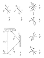
- FIG. 12 schematically illustrates a path of radiation emitted by a transmit antenna 802 via a path 804 toward a reflector element 806.
- the reflector element 806 reflects the radiation over a path 808 in the direction of an object 810. From the object 810, the radiation is reflected by a path 812 back to the reflector element 806. From the reflector element 806, the radiation is reflected on a path 814 to a receiving antenna 816.
- Fig. 8B schematically illustrates a polarization direction 820 of the transmitting antenna 802, wherein it is assumed that the antenna 802 emits linearly polarized radiation.
- the polarization 820 of the radiation emitted by the antenna 802 in the s / p coordinate system is inclined by 45 °.
- Fig. 8C shows a polarization 822 of the receiving antenna 816, which is identical to the polarization 820 of the transmitting antenna 802, but in the s / p coordinate system, although also inclined by 45 °, however tilted by 90 ° relative to the polarization 820 of the transmitting antenna appears.
- FIG. 12 illustrates a linear polarization 824 of the radiation emitted by the transmitting antenna 802 on the path 804 as resulting from the polarization 820 of the transmitting antenna according to FIG Fig. 8B results.
- Fig. 8E shows a polarization 826 of the radiation after the first reflection on the reflector element 806 on the path 808.
- Fig. 8F shows a polarization state 828 of the radiation reflected by the object 810 on the path 812.
- Fig. 8G shows a polarization 830 of the radiation after the second reflection on the reflector element 806 on the path 814. In the polarization state 830, the radiation arrives at the location of the receiving antenna 816.
- the Fig. 8G shows the same polarization state 830 as the Fig. 8F , but with a representation analogous to that of Fig. 8C in which the s-axis points to the right instead of to the right.
- the polarization 822 of the receiving antenna 816 is off Fig. 8C taken over and dashed lines drawn here.
- the polarization 830 of the incident radiation reflected twice at the reflector element 806 lies in the same plane as the polarization 822 of the receiving antenna 816, ie the reception or the detection of the double reflection is preferred when using an uncoated mirror.
- Figs. 9A-9H become polarization states for a two-fold reflection of the received signal according to Fig. 3D illustrated on a mirror with polarization-effective coating.
- the type of representation in the Figs. 9A-9H corresponds to that of Fig. 4A - 4G
- Fig. 9A shows in schematic form a path of the radiation emitted by a transmission antenna 902 is emitted via a path 904 in the direction of a reflector element 906 with polarization-effective coating 907. From the element 906, 907 the radiation is reflected via a path 908 towards an object 910. From the object 710, the radiation is reflected on a path 912 back to the coated reflector element 906, 907. From the reflector element 906, 907 the radiation passes via a path 914 to a receiving antenna 916.
- Fig. 9B illustrates a polarization direction 920 of the transmitting antenna 902, wherein the antenna 902 is again intended to emit linearly polarized radiation.
- the polarization of the radiation emitted by the antenna 902 in the s / p coordinate system is inclined by 45 °.
- Fig. 9C shows a polarization 922 of the receiving antenna 914, which is identical to the polarization 920 of the transmitting antenna 902, but also in the s / p coordinate system also inclined by 45 °, but tilted by 90 ° relative to the polarization 920 of the transmitting antenna.
- FIG. 12 illustrates a linear polarization 924 of the radiation emitted by the transmitting antenna 902 on the path 904 as resulting from the polarization 920 of the transmitting antenna according to FIG Fig. 9B results.
- Fig. 9E shows a polarization 926 of the radiation after reflection on the reflector element 906 with coating 907 on the path 908. Due to the influence of the example dielectric coating 907, the linear polarization 926 is transformed into the elliptical polarization 928.
- Fig. 9F shows a polarization state 928 of the radiation reflected by the object 910 on the path 912.
- the radiation is further elliptically polarized and strikes so on the coated reflector element 906, 907 a.
- FIG. 9G shows a polarization state 930 of the radiation reflected by the coated reflector element 906, 907 on the path 914.
- the renewed influence of the polarization-effective coating 907 can result, for example, in a circular polarization 930, as in FIG Fig. 9G shown.
- the radiation arrives at the location of the receiving antenna 714.
- the Fig. 9H shows the same polarization state 930 as Fig. 9G , but with a representation analogous to that of Fig. 9C with the s-axis instead of pointing to the right.
- the polarization 922 of the receiving antenna 914 is shown in dashed lines. Only a portion of the incident, twice reflected at the coated reflector element 906, 907 and now circularly polarized 930 radiation oscillates in the direction of polarization 922 of the receiving antenna 914, so that the reception or detection of this double mirroring is less preferred than when using an uncoated Mirror, cf. Fig. 8H That is, the double mirroring can be suppressed with a coated mirror, if this is desirable for a specific imaging system or a specific scanner.
- FIG. 4A - 9H illustrates an aspect of an imaging system according to the invention, for example, a targeted generation of a multipath signal by combining an imaging radar sensor or an array of transmitting and receiving antennas with a reflector element, for example.
- a reflective metallic surface A targeted selection of certain portions of the multipath signal is, for example, by transformation of a linear polarization in an elliptical polarization by the reflection on a polarization-effective in this way coating of the reflector element possible.
- the transmitting / receiving antennas should, for example, emit linearly polarized radiation or be sensitive to linearly polarized radiation.
- polarization-effective mirror coating which converts a linear polarization into an elliptical polarization, can increase a reception power of the multiply-mirrored multipath signals compared to an uncoated mirror. In this case, maximizing the reception level of the simple mirroring can lead to a minimization of the reception power of the double mirroring.
- a detected power of a certain portion of a multipath signal is dependent on the presence or absence of a coating, and the exact characteristics of the coating, as further discussed below.
- a low level of simple reflection is detected without coating, ie these signal components are suppressed, while with coating a detectability of this signal component is improved can.
- a maximum level is detected in these arrangements without coating, ie this signal component is emphasized. With a coating, this proportion of the multipath signal in the detection can be reduced.
- a multipath signal can be used especially for improving a frontal object illumination. This is achieved by making the simple reflections particularly well detectable. If the multipath signal is to be used especially for the selective detection of further reflection features, such as e.g. Edges can be achieved by favoring twofold reflections over simple reflections. Such a use is the only one that can be achieved under certain circumstances by means of uncoated mirror. Moreover, according to the invention, it is also possible to use overlays of single and double reflections, if this appears appropriate for optimum imaging quality including good illumination with the best possible suppression of disturbances during image reconstruction.
- the described aspects can be realized for any antenna arrangements, for example for mono- or multistatic constellations, and / or for one-, two- or three-dimensional antenna arrangements.
- Digital Focusing (DBF) methods known in the art may be used.
- the coating of the reflector element can be done with a preferably low-loss dielectric;
- a nonconducting dielectric ie an insulating material, which is to be applied to the reflector element in order to set the preferred use of the available multipath signal with specific thickness and permittivity as a coating.
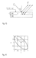
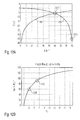
- Fig. 10 is an adjustment of the reception level of certain portions of a multipath signal in the case of a transformation of a linearly polarized electromagnetic wave in an elliptically polarized wave, in particular for the selective selection of single and / or double reflection by applying the Fresnel reflection formulas for a plane-parallel homogeneous dielectric 1002 demonstrated on a metallic half space 1004. This is based on a linearly polarized wave, which is tilted by 45 ° to the surface normal.
- the matrix on the left side of the equation is the scattering matrix of the coated mirror surface using the FSA convention.
- Fig. 11 shows the resulting polarization ellipse 1100.
- the phase shift ⁇ ⁇ determines the shape of the polarization ellipse 1100.
- the line labeled "B" semi-axis represents the relevant polarization axis for the simple reflections.
- the semiaxis marked “A” represents the relevant polarization axis for the two-fold reflection, as shown in FIGS Fig. 4-9 is illustrated.
- the desired phase shift ⁇ ⁇ may be between the perpendicular and parallel polarization components as a function of a desired locking or coupling (more details see below) to the receiving antennas for the simple and doubly mirrored multipath signal components. Then, the relative permittivity of the coating can be determined, with which the desired phase shift ⁇ ⁇ can be achieved. Furthermore, the coating thickness d be set so that the reflection properties in the operating frequency range and for the expected angle of incidence ⁇ i are optimal.
- a coupling C as a function of a phase shift ⁇ ⁇ , between a reflected electric field He and a receiving antenna.
- the coupling or coupling C can be estimated, for example, assuming a metallic non-depolarizing scatterer. With regard to the scattering matrices and the polarization vectors, the FSA convention is again used.
- T ⁇ 1 2 ⁇ 1 1 T
- Fig. 12A illustrates these relationships for easy 1202 and twice in 1204 Spieglung graphically.
- the phase shift ⁇ ⁇ C the maximum coupling between the receiving antenna and reflected electric field He, which in Fig. 12A is represented as a weakening of a reception strength pin decibel (dB).
- Fig. 12B represents the maximum phase shift ⁇ ⁇ as a function of the relative permittivity ⁇ r of the coating material
- Figs. 12A and 12B can the requirements for the permittivity of the coating material determine which are required to achieve a certain constellation of multipath signal components at the receiving antenna.
- Fig. 13 13 illustrates, in the form of a flowchart, a method 1300 for imaging an object 1302.
- the method 1300 may be implemented, for example, as an operating method of an imaging system, such as a personal scanner.
- electromagnetic radiation in a first polarization state is emitted for illuminating the object.
- the radiation can be emitted approximately linearly polarized with a certain vibration level in space from a transmitting antenna.
- a radiation component reflected by the reflector element is converted by a polarization-effective material layer on the reflector element into a polarization state such that the radiation component at the receiver antenna is in the second polarization state.
- a step 1308 radiation of a second polarization state reflected by the object is received.
- the radiation may be received by a receiving antenna, which is preferably sensitive to linear polarization with a particular plane of vibration.
- the oscillation planes of transmit and receive antennas may coincide, or may be tilted relative to each other.
- an image of the object is determined based on the radiation received by the receiving antenna.
- Techniques of synthetic focusing may be upstream of step 1304 on the transmitter side, and / or performed on the receiver side as part of step 1310. These techniques can be adapted to the multipath signal components to be preferably detected.
- the steps are multiple, and may be executed in whole or in part in parallel.
- step 1312 ends in step 1312, for example, with the output of the particular image on a display screen.
Landscapes
- Engineering & Computer Science (AREA)
- Remote Sensing (AREA)
- Radar, Positioning & Navigation (AREA)
- Physics & Mathematics (AREA)
- Computer Networks & Wireless Communication (AREA)
- General Physics & Mathematics (AREA)
- Electromagnetism (AREA)
- Aerials With Secondary Devices (AREA)
- Radar Systems Or Details Thereof (AREA)
Abstract
Description
- Die vorliegende Erfindung betrifft ein System zur Ausleuchtung und Abbildung von Objekten mithilfe elektromagnetischer Strahlung, bspw. Millimeterstrahlung, sowie ein Betriebsverfahren für ein derartiges System.
- Mikrowellen, insbesondere Millimeterwellen, werden zunehmend u.a. für Personenscanner eingesetzt. Millimeterwellen eignen sich zur Detektion metallischer wie auch nichtmetallischer Objekte, bspw. keramischer Objekte wie Messer Gleichzeitig sind Luft und andere Materialien, wie sie etwa für Kleidung verwendet werden, transparent für derartige Strahlung. Somit können Millimeterwellen für berührungslose Scanner zur Detektion unter der Kleidung verborgener Gegenstände eingesetzt werden. Derartige Scanner sind Metalldetektoren überlegen und können diese ergänzen oder ersetzen, bspw. im Bereich von Sicherheitskontrollen an Flughäfen oder sicherheitsrelevanten öffentlichen Einrichtungen.
- Beim Betrieb eines derartigen Scanners wird ein Mikrowellensignal mit einer gegebenen Bandbreite erzeugt und von mindestens einer Antenne in Richtung eines menschlichen Körpers mit ggf. unter der Kleidung verborgenen Objekten ausgesendet. Die Mikrowellensignale werden vom Körper und von den versteckten Objekten reflektiert. Die Reflektionen werden von mindestens einer Antenne empfangen. Sende- und Empfangsantenne können separat vorgesehen sein.
- Ein Scanner kann auch eine Vielzahl von Sende- und/oder Empfangsantennen umfassen. Ein derartiger Scanner kann bspw. in einem multistatischen Modus betrieben werden, bei dem eine Sendeantenne ein Signal aussendet, und Reflektionen dieses Signals nach Amplitude und Phasenlage von mehreren oder allen Empfangsantennen empfangen werden. In einem anderen multistatischen Modus können auch mehrere Sendeantennen gleichzeitig senden, wobei das reflektierte Signal jeder einzelnen Sendeantenne von jeweils einer Mehrzahl von Empfangsantennen empfangen wird.
- Es können Verfahren der Apertursynthese zur Anwendung kommen, bspw. Verfahren der digitalen Keulenformung ("Digital Beamforming", DBF), bei denen eine Fokussierung der ausgesendeten und/oder der empfangenen Strahlung zur Objektabtastung ohne mechanische Bewegung der Antennen und ohne elektromagnetische Bündelung durch Linsen oder dgl. erfolgen kann; stattdessen erfolgt eine Fokussierung nur durch gezielte Ansteuerung der Sendeantennen und/oder Auswertung der von den Empfangsantennen detektierten Signale. Bei letzteren wird bspw. durch einen softwarebasierten Algorithmus ein von einem gegebenen Raumpunkt in Richtung auf mehrere Antennen reflektiertes und dort empfangenes Signal ausgewertet.
-
DE 10 2011 078 539 A1 beschreibt eine Vorrichtung zur Ausleuchtung eines Prüfobjekts, wobei die Vorrichtung mindestens ein Reflektorelement zur Reflektion von Mikrowellensignalen umfasst. Zusätzlich zu den direkt auf das Objekt abgestrahlten und von diesem reflektierten Strahlen werden weitere über das Reflektorelement verlaufende Mikrowellensignale empfangen und zur Rekonstruktion der Abbildung des Prüfobjekts verwendet. Für die synthetische Fokussierung wird dabei von der Vorstellung einer oder mehrerer virtueller Sende- bzw. Empfangsantennen ausgegangen, deren Positionen den an einer Spiegelachse gespiegelten realen Positionen realer Sende- bzw. Empfangsantennen entsprechen. Das Reflektorelement ermöglicht eine verbesserte Ausleuchtung von Objektbereichen, die durch direkt abgestrahlte Signale zu wenig oder gar nicht ausgeleuchtet werden. Allerdings kann es durch die vom Reflektorelement verursachten Spiegelungen des Objekts zu Störungen in der Rekonstruktion, d.h. der Abbildung des Objekts kommen. - Eine Aufgabe der vorliegenden Erfindung besteht darin, ein System und ein Verfahren zur Abbildung eines Objekts vorzuschlagen, bei dem durch ein Reflektionselement verursachte Störungen in der Rekonstruktion minimiert werden können, und damit sowohl eine verbesserte Ausleuchtung als auch eine verbesserte Abbildungsqualität erzielt werden können.
- Die Aufgabe wird für das System durch die Merkmale des Anspruchs 1 und für das Verfahren durch die Merkmale des Anspruchs 13 gelöst.
- Erfindungsgemäß wird ein System zur Abbildung eines Objekts vorgeschlagen, welches mindestens eine Sendeantenne zur Aussendung elektromagnetischer Strahlung eines ersten Polarisationszustandes zur Ausleuchtung des Objekts umfasst. Mindestens eine Empfangsantenne ist zum Empfang vom Objekt reflektierter Strahlung eines zweiten Polarisationszustandes vorgesehen. Mindestens ein Reflektorelement dient zur Reflektion von der Sendeantenne ausgesendeter Strahlung in Richtung auf das Objekt und/oder zur Reflektion vom Objekt reflektierter Strahlung in Richtung auf die Empfangsantenne. Eine polarisationswirksame Materialschicht ist auf dem Reflektorelement vorgesehen, um einen vom Reflektorelement reflektierten Strahlungsanteil in einen Polarisationszustand derart zu überführen, dass der Strahlungsanteil an der Empfangsantenne im zweiten Polarisationszustand ist. Eine Verarbeitungseinheit dient zur Bestimmung der Abbildung des Objekts basierend auf der von der Empfangsantenne empfangenen Strahlung.
- Das System kann zur Ausleuchtung und Abbildung eines Objekts wie etwa eines Menschen oder auch eines Tieres oder unbelebten Objekts ausgelegt sein. Bestimmte Ausführungsformen des Systems haben den Verwendungszweck, am Körper eines Menschen unter dessen Kleidung verborgene Objekte zu detektieren, was nicht-metallische Objekte wie etwa keramische Waffen oder körpernah geformte Objekte aus plastischen Sprengstoffen einschließen kann.
- Bei den Sende- und/oder Empfangsantennen kann es sich bspw. um Hornantennen handeln. Die elektromagnetische Strahlung kann etwa Mikrowellen umfassen, also bspw. Strahlung im Wellenlängenbereich von 1 Millimeter bis 10 Millimeter.
- Der erste Polarisationszustand der ausgesendeten Strahlung und der zweite Polarisationszustand der empfangenen Strahlung können übereinstimmen oder können unterschiedlich sein, d.h. die Sende- und die Empfangsantenne können zur Aussendung bzw. zum Empfang von Strahlung ein- und desselben Polarisationszustandes ausgebildet sein, oder die Empfangsantenne ist zum Empfang von Strahlung eines Polarisationszustandes ausgebildet, der sich vom Polarisationszustand der ausgesendeten Strahlung unterscheidet. Ein Polarisationszustand kann auch die Aussendung bzw. den Empfang unpolarisierter Strahlung betreffen.
- Bei bestimmten Ausführungsformen betrifft sowohl der erste Polarisationszustand als auch der zweite Polarisationszustand jeweils eine lineare Polarisation, d.h. die Sendeantenne ist zur Aussendung linear polarisierter Strahlung ausgebildet, und die Empfangsantenne ist zum Empfang linear polarisierter Strahlung ausgebildet. Bspw. kann die Sendeantenne zur Aussendung linear polarisierter Strahlung einer ersten Schwingungsrichtung ausgebildet sein, und die Empfangsantenne kann zum Empfang linear polarisierter Strahlung einer zweiten Schwingungsrichtung ausgebildet sein. Die erste und die zweite Schwingungsrichtung können gleich sein, oder können unterschiedlich sein, und können bspw. um 80° bis 100°, bevorzugt 90°, gegeneinander gekippt sein.
- Das Reflektorelement kann eine ebene oder auch gekrümmte reflektierende Oberfläche haben. Das Reflektorelement kann etwa aus einem spiegelnden metallischen Material bestehen.
- Die polarisationswirksame Materialschicht kann eine Beschichtung, Auflage, Platte, Scheibe, Folie, einen Überzug, eine Plattierung oder Abscheidung auf dem Reflektorelement umfassen. Die Materialschicht kann wirksam sein, um eine lineare Polarisierung einfallender Strahlung in eine elliptische Polarisierung der reflektierten Strahlung zu transformieren. Hier und im Folgenden soll eine elliptische Polarisierung auch den Sonderfall einer zirkularen Polarisierung mit umfassen.
- Die polarisationswirksame Materialschicht kann auch ausgebildet sein, um eine lineare Polarisation in eine andere lineare Polarisation zu transformieren, oder um eine Reflektion am Reflektorelement so zu bewirken, dass eine lineare Polarisation beibehalten wird, d.h. eine Schwingungsrichtung der ein- und ausfallenden Strahlung unverändert bleibt.
- Das Material der Schicht kann ein Dielektrikum umfassen. Die Beschichtung kann bevorzugt Polyethylenterephthalat (PET), Polyvinylchlorid (PVC), Polycarbonat (PC), Glas, Acrylglas, und/oder Kautschuk umfassen; diese Auflistung ist jedoch nicht abschließend und es können alternativ oder zusätzlich andere dielektrisch wirksame und/oder isolierende Materialien verwendet werden.
- Ausführungsformen polarisationswirksamer Auflagen oder Beschichtungen können etwa Strichgitter oder vergleichbar wirkende Anordnungen wie etwa Schichtungen oder Beschichtungen mit elektromagnetisch wirksamen Partikeln wie etwa Nanopartikeln umfassen. Beispielsweise kann von zwei vorgesehenen Reflektorelementen eines mit einer Beschichtung versehen sein, die eine Polarisation in eine Strahlung einbringt, und das andere Reflektorelement kann auf eine vorhandene Polarisation einwirken, indem sie bspw. eine lineare in eine elliptische Polarisation transformiert.
- Eine Dicke der Materialschicht kann kleiner als ein Viertel einer Wellenlänge der elektromagnetischen Strahlung gewählt werden. Die Dicke kann auch größer als ein Viertel der Wellenlänge gewählt werden, sie sollte jedoch außerhalb eines Bereiches um ein Viertel der Wellenlänge herum liegen, bei der eine einfallende Strahlung unerwünscht stark absorbiert wird. Bei verschiedenen Ausführungsformen kann die Dicke also in geeigneter Weise unter einem Viertel der Wellenlänge liegen, oder über einem Viertel der Wellenlänge, aber unter der halben Wellenlänge liegen, usw..
- Störungen in der Rekonstruktion des Objekts können u. U. auch durch eine geeignete Einstellung der Empfangspegel der Spiegelungen an der Empfangsantenne minimiert werden. Material und/oder Dicke des Beschichtungsmaterials kann daher auch nach allgemeinem Reflexions- bzw. Absorptionsvermögen im betreffenden Wellenlängenbereich ausgewählt werden.
- Eine relative Permittivitätszahl des Materials der Schicht kann zwischen 2 und 4 liegen, bevorzugt zwischen 2,5 und 3,5. Bei alternativen Ausführungsformen wird eine relative Permittivitätszahl des Schichtmaterials größer als 5, bevorzugt größer oder gleich 6 gewählt.
- Bei Ausführungsformen des erfindungsgemäßen Systems ist die Materialschicht derart ausgebildet, dass ein vom Reflektorelement einfach reflektierter Strahlungsanteil bevorzugt an der Empfangsantenne detektiert wird. Zusätzlich oder alternativ kann der Empfang anderer Strahlungsanteile an der Empfangsantenne unterdrückt sein, etwa von Mehrwegeanteilen der Strahlung, die zweifach am Reflektorelement reflektiert werden.
- Bei einigen der vorgenannten Ausführungsformen ist die Materialschicht derart polarisationswirksam ausgebildet, dass an der Empfangsantenne eine Überlagerung aus dem einfach reflektierten Strahlungsanteil und einem vom Reflektorelement zweifach reflektierten Strahlungsanteil detektiert wird. Beide Anteile können bspw. derart polarisiert sein, dass sie etwa gleich stark an die Empfangsantenne ankoppeln.
- Bei manchen Ausführungsformen des erfindungsgemäßen Systems ist das Reflektorelement mit der Materialschicht in Bezug auf eine Ebene, in der die Sende- und/oder Empfangsantennen angeordnet sind, um 45° bis 135°, bevorzugt 80° bis 100°, verkippt. Sind die Antennen in einer senkrechten Ebene über einem Boden angeordnet, kann das Reflektorelement sich parallel zum Boden erstrecken, und kann etwa auf dem Boden liegen oder eine Bodenplatte des Systems bilden, oder kann in Überkopfhöhe parallel zum Boden angeordnet sein.
- Das System kann eine Mehrzahl von Sende- und/oder Empfangsantennen in einer monostatischen, bistatischen oder multistatischen Konstellation umfassen. Die Verarbeitungseinheit kann ausgebildet sein, um eine senderseitige und/oder empfangsseitige synthetische Fokussierung vorzunehmen.
- Erfindungsgemäß wird weiterhin ein Verfahren zur Abbildung eines Objekts vorgeschlagen, welches die folgenden Schritte umfasst: Aussenden elektromagnetischer Strahlung eines ersten Polarisationszustandes zur Ausleuchtung des Objekts; Reflektion, von mindestens einem Reflektorelement, von der Sendeantenne ausgesendeter Strahlung in Richtung auf das Objekt und/oder vom Objekt reflektierter Strahlung in Richtung auf die Empfangsantenne, wobei durch eine polarisationswirksame Materialschicht auf dem Reflektorelement ein vom Reflektorelement reflektierter Strahlungsanteil in einen Polarisationszustand derart überführt wird, dass der Strahlungsanteil an der Empfangsantenne im zweiten Polarisationszustand ist; Empfangen vom Objekt reflektierter Strahlung eines zweiten Polarisationszustandes; und Bestimmen der Abbildung des Objekts basierend auf der von der Empfangsantenne empfangenen Strahlung.
- Aus Sicht der Erfindung stellt ein bekanntes Abbildungssystem mit unbeschichtetem Reflektorelement nur einen Sonderfall dar, bei dem bestimmte Spiegelbilder bevorzugt detektierbar sind, andere hingegen unterdrückt werden. Mit der erfindungsgemäß vorgesehenen polaritätswirksamen Beschichtung kann jedoch Einfluss darauf genommen werden, welche der von dem Reflektorelement erzeugten Spiegelbilder in welcher Stärke von den Empfangsantennen detektiert werden; dies umfasst auch gewünschte Überlagerungen von Spiegelbildern. Dadurch erhält der Fachmann zusätzliche Konfigurationsmöglichkeiten an die Hand, um sowohl Ausleuchtung als auch Abbildungsqualität eines konkreten Systems zu optimieren.
- So kann die Ausleuchtung in Randbereichen eines Detektors verbessert werden, etwa im Fuß- bzw. Fußbodenbereich von Personenscannern, wobei Störungen in der Rekonstruktion minimiert werden können. Der Einsatzbereich von Reflektorelementen zur verbesserten Ausleuchtung von Objekten wird erweitert; so können etwa bei existierenden Konfigurationen weitere Reflektorelemente hinzugefügt werden, um eine Ausleuchtung weiter zu verbessern.
- Eine erfindungsgemäße Beschichtung kann auf einfache Weise durch Auflegen oder Kleben von Schichten, Folien, Matten oder Platten aus handelsüblichen Materialien wie PVC oder Glas auf ein z.B. metallisches Reflektorelement kostengünstig realisiert werden. Sollte eine Ansteuerung der Sendeantennen und/oder Auswertung der empfangenen Signale anzupassen sein, erfordert dies meist lediglich Änderungen an einer Software, so dass neben dem Vorsehen beschichteter Reflektorplatten, bspw. einer beschichteten Fußbodenplatte, keine weiteren Änderungen an einer Hardwarekonstellation erforderlich sind. Eine Aufrüstung existierender Systeme ist somit einfach möglich, indem ein existierender Reflektor mit einer Beschichtung versehen oder durch einen beschichteten Reflektor ersetzt wird, und ggf. eine Softwareaktualisierung vorgenommen wird.
- Weitere Aspekte und Vorteile der Erfindung werden nachfolgend anhand der beigefügten Zeichnungen beschrieben. Hierbei zeigen:
- Fig. 1A
- in schematischer Form ein Ausführungsbeispiel eines erfindungsgemäßen Abbildungssystems;
- Fig. 1B
- eine Detailansicht einer Antennenanordnung des Abbildungssystems aus
Fig. 1A ; - Fig. 2
- eine Schnittansicht eines Ausführungsbeispiels eines erfindungsgemäß beschichteten Reflektorelements;
- Fig. 3A-D
- schematische Darstellungen verschiedener Laufwege von ausgesendeten und reflektierten Strahlen im System der
Fig. 1A ; - Fig. 4A-G
- schematische Darstellungen zur Transformation von Polarisationszuständen entlang des Laufweges der
Fig. 3B bei einem unbeschichteten Reflektorelement; - Fig. 5A-G
- schematische Darstellungen zur Transformation von Polarisationszuständen entlang des Laufweges der
Fig. 3B bei einem beschichteten Reflektorelement; - Fig. 6A-G
- schematische Darstellungen zur Transformation von Polarisationszuständen entlang des Laufweges der
Fig. 3C bei einem unbeschichteten Reflektorelement; - Fig. 7A-G
- schematische Darstellungen zur Transformation von Polarisationszuständen entlang des Laufweges der
Fig. 3C bei einem beschichteten Reflektorelement; - Fig. 8A-H
- schematische Darstellungen zur Transformation von Polarisationszuständen entlang des Laufweges der
Fig. 3D bei einem unbeschichteten Reflektorelement; - Fig. 9A-H
- schematische Darstellungen zur Transformation von Polarisationszuständen entlang des Laufweges der
Fig. 3D bei einem beschichteten Reflektorelement; - Fig. 10
- ein Diagramm zur Reflektion einer elektromagnetischen Welle an einem erfindungsgemäß beschichteten Reflektorelement;
- Fig. 11
- eine Veranschaulichung einer elliptischen Polarisation nach Reflektion an einem erfindungsgemäß beschichteten Reflektorelement;
- Fig. 12A
- ein Diagramm zur Ankopplung einer reflektierten elektromagnetischen Welle in Abhängigkeit von einem Phasenversatz nach Reflektion an einem erfindungsgemäß beschichteten Reflektorelement;
- Fig. 12B
- ein Diagramm zur Darstellung eines maximalen Phasenversatzes in Abhängigkeit von einer Permittivität eines Beschichtungsmaterials; und
- Fig. 13
- ein Diagramm zur Veranschaulichung einer Betriebsweise des Systems aus
Fig. 1 . - In
Fig. 1 ist ein Ausführungsbeispiel eines erfindungsgemäßen Abbildungssystems 100 schematisch dargestellt. Das System 100 umfasst einen senkrechten Rahmen 102, in dem eine Vielzahl Sendeantennen 104 sowie Empfangsantennen 106 angeordnet sind. Die Empfangsantennen 104 sind ausgebildet, um linear polarisierte Mikrowellen in einen Bereich 108 vor dem Rahmen 102 einzustrahlen, um ein dort befindliches Objekt auszuleuchten, bspw. eine Person.
Die Empfangsantennen 106 dienen zum Empfang vom Objekt reflektierter Strahlung und sind zum Empfang linear polarisierter Strahlung ausgebildet. - Eine Verarbeitungseinheit 110 dient der Ansteuerung der Antennen 104, 106 und der Bestimmung einer Abbildung des Objekts basierend auf Signalen, welche die von den Empfangsantennen 106 empfangene Strahlung repräsentieren. Die Verarbeitungseinheit 110 kann zur sender- und/oder empfangsseitigen synthetischen Fokussierung ausgebildet sein. Die Antennen 104, 106 können bspw. in einer multistatischen Konfiguration betrieben werden.
- Auf dem Boden vor dem Rahmen 102 befindet sich eine Bodenplatte 112 mit einem Reflektorelement 114. Platte 112 und Element 114 sind einem Winkel von 90° zum Rahmen 102 mit den Antennen 104, 106 angeordnet und begrenzen den Ausleuchtungsbereich 108, in diesem Beispiel nach unten. Von den Sendeantennen 104 ausgesendete Mikrowellen werden durch das Reflektorelement 114 in Richtung auf das Objekt reflektiert. Außerdem wird vom Objekt reflektierte Strahlung in Richtung auf die Empfangsantennen 106 reflektiert. Das Element 114 kann etwa eine metallische reflektierende Platte umfassen, auf die sich eine auszuleuchtende Person in einem durch das Symbol 116 bezeichneten Bereich stellt.
- Auf das Reflektorelement 114, d.h. auf dessen dem Ausleuchtungsbereich 108 zugewandter Seite, ist eine polarisationswirksame Beschichtung 118 aufgebracht. Diese dient dazu, einen vom Reflektorelement 114 reflektierten Strahlungsanteil in einen Polarisationszustand derart zu überführen, dass dieser Strahlungsanteil an den Empfangsantennen 106 detektiert wird, weil sein Polarisationszustand mit der linearen Polarisation der Antennen 106 übereinstimmt. Im vorliegenden Beispiel transformiert die Beschichtung 118 auftreffende, linear polarisierte Strahlung in elliptisch polarisierte Strahlung.
-
Fig. 2 ist eine schematisierte Schnittansicht der Bodenplatte 112 mit Reflektorelement 114 und Beschichtung 118. Das Element 114 kann bspw. als reflektierende Metallplatte ausgeführt sein, wobei das Metall etwa Aluminium sein kann. Die metallische Schicht 112 kann ausreichend dick sein, um bspw. für eine Verwendung als eine oder in einer Bodenplatte 112 geeignet zu sein. Zusätzlich oder alternativ kann das Reflektorelement 112 durch weitere Schichten oder Platten (nicht gezeigt) mechanisch stabilisiert sein, die dem Reflektorelement 112 an der dem Ausleuchtungsbereich 108 abgewandten Seite angelagert sind. - In Richtung auf den Ausleuchtungsbereich 108 kann auf das Reflektorelement 112 eine Lackschicht 202 aufgebracht sein. Die Schicht 202 kann dem Schutz des Reflektorelements 112 vor mechanischer und/oder chemischer Beanspruchung dienen und kann bspw. einen Klarlack umfassen. Bei anderen Ausführungsbeispielen kann eine Schutz- bzw. Lackschicht auch weggelassen werden.
- Auf der Lackschicht 202 ist eine Klebeschicht 204 aufgebracht, die der mechanischen Befestigung der darüberliegenden Beschichtung 118 am Reflektorelement 114 bzw. der Bodenplatte 112 dient. Das Material der Klebeschicht 204 sollte in Abhängigkeit von den Materialien der angrenzenden Schichten 118 und 202 bzw. 112 sowie gemäß dem gewünschten Herstellungsprozess gewählt werden; für ein Heißklebeverfahren zum Aufkleben der Beschichtung 114 auf das Reflektorelement 112 kann bspw. ein Schmelzklebstoff verwendet werden.
- Eine Befestigung der Beschichtung 114 auf dem Reflektorelement kann statt durch Kleben auch anders erfolgen, bspw. kann eine mechanische Befestigung mittels Klammern, Schrauben oder Nieten erfolgen. Ist das Reflektorelement Teil einer Bodenplatte, kann eine polarisationswirksame Schicht, Platte oder Auflage im einfachsten Fall ohne weitere Befestigung auch nur auf das Reflektorelement aufgelegt werden; bspw. können Reflektorelement und Auflage durch einen gemeinsamen Rahmen gehalten werden.
- Somit kann die Klebeschicht 204 wie auch die Lackschicht 202 bei anderen Ausführungsbeispielen auch weggelassen werden. Sind jedoch eine oder mehrere Schichten vorhanden, wie eine Lackschicht vergleichbar zur Schicht 202, eine Klebeschicht vergleichbar zur Schicht 204, und/oder weitere oder andere Schichten, tragen diese u.U. zur Polarisationswirksamkeit der Beschichtung 118 bei. In diesem Sinne sind Schichten wie die Schichten 202 und 204 zur Beschichtung 118 zuzurechnen. Nachfolgend wird dieser Aspekt aus Gründen der Klarheit nicht jedesmal explizit erwähnt.
- Die polarisationswirksame Beschichtung 118 kann ein dielektrisches Material umfassen. Die Beschichtung 118 kann etwa aus einem Material wie bspw. Glas oder einem glasartigen Material bestehen, einschließlich Polycarbonat (PC), Polymethylmethacrylat (PMMA) bzw. Acryl- oder Plexiglas, Polyethylenterephthalat (PET), oder anderen Kunststoffgläsern. Zusätzlich oder alternativ kann das Material der Beschichtung 118 auch andere polarisationswirksame Materialien umfassen, wie bspw. Polyethylenterephthalat (EPT), Polyvinylchlorid (PVC) oder Kautschuk, bspw. Polyacryl-Kautschuk und/oder C1-Kautschuk. Verwendbar sind auch Materialien mit einstellbarer bzw. ansteuerbarer Permittivität, die bspw. Flüssigkristalle enthalten.
- Eine Dicke 206 der Lackschicht 202 kann zwischen 10 Mikrometern und 70 Mikrometern liegen, bevorzugt zwischen 10 Mikrometern und 60 Mikrometern, besonders bevorzugt zwischen 10 Mikrometern und 50 Mikrometern. Eine Dicke 208 der Klebeschicht 204 kann zwischen 10 Mikrometern und 70 Mikrometern betragen, bevorzugt zwischen 10 Mikrometern und 60 Mikrometern, besonders bevorzugt zwischen 10 Mikrometern und 50 Mikrometern.
- Soll die Polarisationswirksamkeit im wesentlichen durch die Beschichtung 118 bestimmt sein, sollten die Dicken 206 und 208 jeweils möglichst dünn gewählt werden. Ist alternativ eine Polarisationswirksamkeit der Schichten 202 und/oder 204 gut bekannt und kann zu einer gewünschten Polarisationswirksamkeit beitragen, kann diese für die effektive bzw. gesamte Polarisationswirksamkeit in Betracht gezogen werden. So sind Ausführungsbeispiele denkbar, bei denen auf ein Reflektorelement lediglich eine Schicht aufgetragen ist, die bspw. sowohl als Schutz dient (Schutzlack) als auch in der gewünschten Weise polarisationswirksam ist.
- Eine Dicke 210 der Beschichtung 118 ist abhängig von der gewünschten Polarisationswirksamkeit zu wählen. Die (effektive bzw. strahlungswirksame) Dicke 210 kann bspw. so ausgelegt werden, dass sie kleiner ist als ein Viertel einer Wellenlänge der verwendeten Strahlung unter Beachtung einer Permittivitätszahl eines Dielektrikums, wenn ein solches für die Beschichtung 118 verwendet wird. Bei Frequenzen der verwendeten Strahlung im Bereich von 30 Gigahertz bis 100 Gigahertz, bevorzugt im Bereich von 70 Gigahertz bis 80 Gigahertz, ergeben sich Wellenlängen von etwa 10 Millimetern bis 3 Millimetern, bevorzugt etwa 3,7 Millimetern bis 4,3 Millimetern.
- Wird als Beschichtungsmaterial etwa Acrylglas mit einer relativen Permittivitätszahl von 2,8 gewählt, kann eine Dicke 210 zwischen 250 Mikrometern und 600 Mikrometern, bevorzugt 300 Mikrometern und 400 Mikrometern, gewählt werden. Bei einem konkreten Ausführungsbeispiel kann die Dicke 210 des verwendeten Acrylglases zu 350 Mikrometern gewählt werden. Hierbei kann berücksichtigt werden, dass sich bei einer Lackschicht 202 mit einer Dicke 206 von 50 Mikrometern und einer Klebeschicht 204 mit einer Dicke 208 von 50 Mikrometern eine effektive relative Permittivität von etwa 3,1 einstellen kann; der detaillierte Wert ist abhängig von den optischen Eigenschaften der Lack- und Klebeschicht.
- Wird als Material der Schicht 118 PVC gewählt, so kann eine Dicke 210 dieser Schicht 118 zwischen 200 Mikrometern und 500 Mikrometern, bevorzugt 200 Mikrometern und 300 Mikrometern, gewählt werden. Bei einem konkreten Ausführungsbeispiel kann die Dicke 210 der verwendeten PVC-Schicht 118 zu 220 Mikrometern gewählt werden.
- Die
Figuren 3A - 3D zeigen schematisch mögliche unterschiedliche Laufwege von Strahlen, die von einem Antennenelement 120 des Systems 100 ausFig. 1 in Richtung auf ein Objekt 302 ausgesendet werden. Durch die Verwendung des Reflektorelements 114 werden Mehrwegesignale erzeugt, d.h. es entstehen unterschiedliche Spiegelbilder am Ort des Antennenelements 120. - In
Fig. 1B wird der Aufbau des Antennenelements 120 skizziert. Das Element 120 umfasst eine Mehrzahl von Sendeantennen 104 und eine Mehrzahl von Empfangsantennen 106. Die Sendeantennen 104 können in einem senkrechten Muster 122 übereinander und die Empfangsantennen 106 in einem separaten horizontalen Muster 124 angeordnet sein. Auf eine derartige Anordnung wird aus Gründen der Erläuterung nachfolgend Bezug genommen. Alternativ können Sende- und Empfangsantennen aber auch in anderen, auch überlappenden Mustern, angeordnet sein, bspw. alternierend in einem gemeinsamen Muster. -
Fig. 3A veranschaulicht einen direkten Laufweg 304 von Strahlung, die vom Antennenelement 120, genauer der Struktur 122 ausgesendet wird. Die Strahlung trifft auf das Objekt 302 und gelangt unmittelbar, d.h. ohne Reflektion am Reflektorelement 114, zurück zum Antennenelement 120 und kann dort von den Empfangsantennen der Struktur 124 detektiert werden. -
Fig. 3B veranschaulicht eine einfache Spiegelung des Objekts 302 durch das Reflektorelement 114, nämlich eine Spiegelung des Empfangssignals. Auf dem Laufweg 304 ausgesendete Strahlung wird am Objekt 302 in Richtung auf das Reflektorelement 114 reflektiert, wird am Reflektorelement 114 reflektiert und gelangt somit auf dem Laufweg 306, 308 zu den Empfangsstrukturen 124. Dies ist äquivalent zu einem virtuellen Laufweg 306, 310, bei dem gedacht das Reflektorelement bzw. der Spiegel 114 wegfällt und die vom Objekt 302 reflektierte Strahlung auf dem Laufweg 306, 310 an virtuelle Empfangsstrukturen 312 gelangt, die sich unterhalb des Reflektorelements 114 bzw. der dazugehörigen Bodenplatte befinden. Die Position der Empfangsstrukturen 312 entspricht derjenigen der Empfangsstrukturen 124, jedoch gespiegelt an einer Spiegelachse, die in der Ebene der Reflektorplatte 114 liegt. -
Fig. 3C veranschaulicht eine weitere einfache Spiegelung des Objekts 302 durch das Reflektorelement 114, nämlich eine Spiegelung des Sendesignals. Auf dem Laufweg 308 ausgesendete Strahlung wird am Reflektorelement 114 in Richtung auf das Objekt 302 reflektiert, wird am Objekt 302 nochmals reflektiert und gelangt so auf dem Laufweg 304 zu den Empfangsstrukturen 106. Dies ist äquivalent zu einem virtuellen Laufweg 310, 306, bei dem Strahlung von einer virtuellen Sendestruktur 314 unterhalb des Reflektorelements 118 auf das Objekt 302 fällt und von dort in Richtung auf die reale Empfangsstruktur 106 gelangt. -
Fig. 3D veranschaulicht eine zweifache Spiegelung des Objekts 302 durch das Reflektorelement 114. Hierbei wird auf dem Laufweg 308 ausgesendete Strahlung am Reflektorelement 114 in Richtung auf das Objekt 302 reflektiert. Am Objekt 302 wird die Strahlung zurück zum Reflektorelement 114 reflektiert und dort in Richtung auf die Empfangsstrukturen 106 reflektiert. Dies ist äquivalent zu einem virtuellen Laufweg 310, 306, 306, 310, bei dem Strahlung von der virtuellen Sendestruktur 314 unterhalb des Reflektorelements 118 auf das Objekt 302 fällt und von dort zurück in Richtung auf die virtuelle Empfangsstruktur 312 gelangt. - Die in den
Fig. 3B und 3C veranschaulichte einfache Spiegelung bewirkt eine lückenlose Vergrößerung der effektiv ausgeleuchteten Apertur in Richtung der Spiegelfläche, d.h. im Beispiel derFig. 1 unter den Boden bzw. die Bodenplatte 112. Insbesondere kann die Ausleuchtung von Objekten bzw. Objektbereichen verbessert werden, die sich im wesentlichen parallel zur Antennen- bzw. Sensoranordnung erstrecken, also etwa parallel zum Rahmen 102 inFig. 1 . Hierzu muss sich das Reflektorelement, d.h. die Spiegelfläche in geeigneter Weise zwischen Antennenanordnung und Rahmen erstrecken. Im Beispiel eines Personenscanners kann sich die Ausleuchtung des Unterschenkels einschließlich dort etwa vorhandener Objekte verbessern, wenn die Person auf (oder unmittelbar hinter) einer metallischen Bodenplatte steht, und z.B. auf dem Symbol 116 des Systems 100 inFig. 1 steht. - Die in
Fig. 3D veranschaulichte zweifache Spiegelung bewirkt eine Verbesserung der Detektion von in Bezug auf die Ebene der Antennenanordnung stark geneigten Objekten. Dies schließt die erstmalige oder verbesserte Detektion von Kanten ein. - Mit unbeschichtetem Reflektorelement wird lediglich ein bestimmtes Mehrwegesignal erzeugt, d.h. eine bestimmte Überlagerung von einfachen und zweifachen Spiegelungen. Mit erfindungsgemäß beschichteten Spiegeln kann die Art des Mehrwegesignals kontrolliert werden, d.h. es kann eine gewünschte Kombination von einfachen und zweifachen Spiegelungen mit einer für den konkreten Anwendungsfall optimierten Ausleuchtung bei minimalen Störungen in der Rekonstruktion herbeigeführt werden. Dies wird über eine erfindungsgemäße polarisationswirksame Beschichtung auf dem Reflektorelement erreicht.
- Nachfolgend werden zunächst für beispielhafte Konstellationen von einfachen und zweifachen Spiegelungen Änderungen von Polarisationszuständen entlang von Strahlungs- bzw. Signalwegen beschrieben, und zwar jeweils für ein unbeschichtetes Reflektorelement und für ein beschichtetes Reflektorelement.
- In den
Fig. 4A - 4G werden Polarisationszustände für eine einfache Spiegelung des Empfangssignals gemäßFig. 3B an einem unbeschichteten Spiegel veranschaulicht.Fig. 4A zeigt nochmals in schematischer Form einen Laufweg der Strahlung, die von einer Sendeantenne 402 über einen Pfad bzw. Weg 404 in Richtung auf ein Objekt 406 ausgesendet wird. Vom Objekt 406 wird die Strahlung über einen Laufweg 408 in Richtung auf ein unbeschichtetes Reflektorelement 410 reflektiert. Vom Element 410 wird die Strahlung über einen Laufweg 412 zu einer Empfangsantenne 414 reflektiert. -
Fig. 4B veranschaulicht schematisch eine Polarisationsrichtung 420 der Sendeantenne 402, wobei angenommen wird, dass die Antenne 402 linear polarisierte Strahlung aussendet. Bei der Darstellung inFig. 4A wird die FSA("Forward Scattering Alignment")-Konvention zugrundegelegt. Hierbei entspricht die z-Koordinate eines lokalen rechtshändigen Koordinatensystems der Ausbreitungsrichtung einer elektromagnetischen Welle, die x- und y-Koordinaten entsprechen einer s- bzw. p-Achse, wobei die s- bzw. p-Achse eine Orientierung senkrecht bzw. parallel zu einem Normalenvektor einer als eben angenommenen Oberfläche des Reflektorelements 410 bezeichnen. - Es werden Verhältnisse betrachtet, bei der Strahlung etwa unter einem Winkel von 45° zu einem Normalenvektor der Oberfläche des Reflektorelements 410 auf das Reflektorelement 410 einfällt, bzw. von der Oberfläche des Reflektorelements 410 reflektiert wird. Diese Verhältnisse sind etwa bei dem in
Fig. 1 dargestellten System näherungsweise für die in Bodennähe befindliche Antennenanordnung 120 erfüllt, und zwar in Bezug etwa auf eine Ausleuchtung von Unterschenkeln einer Person, die auf dem Symbol 116 steht. Die Diskussion gilt aber ebenso für Einfalls- bzw. Ausfallswinkel in der Nähe von 45°, also etwa in einem Bereich von 30° bis 60°. - Die Polarisation der von der Antenne 402 ausgesendeten Strahlung ist im s/p-Koordinatensystem um 45° geneigt, wie in
Fig. 4B gezeigt.Fig. 4C zeigt eine Polarisation 422 der Empfangsantenne 414. Die Polarisation 422 der Empfangsantenne 414 ist identisch zur Polarisation 420 der Sendeantenne 402. Aufgrund der FSA-Konvention erscheinen die Sende- und Empfangspolarisation orthogonal, d.h. die Polarisation 422 der Empfangsantenne 414 ist im s/p-Koordinatensystem ebenfalls um 45° geneigt, erscheint allerdings um 90° gegenüber der Polarisation 420 der Sendeantenne gedreht (vergleiche die unterschiedliche Orientierung der s-Achse in denFig. 4B und 4C ). -
Fig. 4D veranschaulicht eine lineare Polarisation 424 der von der Sendeantenne 402 ausgesendeten Strahlung auf dem Laufweg 404, wie sie sich aus der Polarisation 420 der Sendeantenne gemäßFig. 4B ergibt.Fig. 4E zeigt eine Polarisation 426 der Strahlung nach der Reflektion am Objekt 406 auf dem Laufweg 408. Hierbei wird angenommen, dass eine Reflektion an nicht depolarisierenden Oberflächen des Objekts 406 erfolgt, wie dies etwa für menschliche Hautoberflächen oder glatte metallische Flächen der Fall ist. -
Fig. 4F zeigt einen Polarisationszustand 428 der vom Reflektorelement 410 reflektierten Strahlung auf dem Laufweg 412. Im Polarisationszustand 428 trifft die Strahlung am Ort der Empfangsantenne 414 ein. DieFig. 4G zeigt denselben Polarisationszustand 428 wie dieFig. 4F , allerdings mit einer Darstellungsweise analog zu derjenigen derFig. 4C , bei der die s-Achse statt nach rechts nach links zeigt. Die Polarisation 422 der Empfangsantenne 414 ist gestrichelt eingezeichnet. Die Polarisationen 428 der einfallenden, einfach am Reflektorelement 410 reflektierten Strahlung ist orthogonal zur Polarisation 422 der Empfangsantenne 414, d.h. der Empfang bzw. die Detektion dieser einfachen Spiegelung ist bei Verwendung eines unbeschichteten Spiegels unterdrückt. - In den
Fig. 5A - 5G werden Polarisationszustände für eine einfache Spiegelung des Empfangssignals gemäßFig. 3B an einem Spiegel mit polarisationswirksamer Beschichtung veranschaulicht. Die Art der Darstellung in denFig. 5A - 5G entspricht derjenigen derFig. 4A - 4G .Fig. 5A zeigt in schematischer Form einen Laufweg der Strahlung, die von einer Sendeantenne 502 über einen Weg 504 in Richtung auf ein Objekt 506 ausgesendet wird. Vom Objekt 506 wird die Strahlung über einen Laufweg 508 in Richtung auf ein Reflektorelement 510 mit Beschichtung 511 reflektiert. Vom Element 510, 511 wird die Strahlung über einen Laufweg 512 zu einer Empfangsantenne 514 reflektiert. -
Fig. 5B veranschaulicht eine Polarisationsrichtung 520 der Sendeantenne 502, wobei die Antenne 502 wiederum linear polarisierte Strahlung aussendet. Die Polarisation der von der Antenne 502 ausgesendeten Strahlung im s/p-Koordinatensystem ist wiederum um 45° geneigt.Fig. 5C zeigt eine Polarisation 522 der Empfangsantenne 514, die identisch zur Polarisation 520 der Sendeantenne 502 ist, die jedoch im s/p-Koordinatensystem zwar ebenfalls um 45° geneigt, allerdings um 90° gegenüber der Polarisation 520 der Sendeantenne gekippt erscheint. -
Fig. 5D veranschaulicht eine lineare Polarisation 524 der von der Sendeantenne 502 ausgesendeten Strahlung auf dem Laufweg 504, wie sie sich aus der Polarisation 520 der Sendeantenne gemäßFig. 5B ergibt.Fig. 4E zeigt eine Polarisation 526 der Strahlung nach der Reflektion am Objekt 506 auf dem Laufweg 508.Fig. 5F zeigt einen Polarisationszustand 528 der vom Reflektorelement 510 und dessen Beschichtung 511 reflektierten Strahlung auf dem Laufweg 512. Durch den Einfluss der z.B. dielektrischen Beschichtung 511 wird die lineare Polarisation 526 in die elliptische Polarisation 528 transformiert. - Die Strahlung trifft also mit elliptischer Polarisierung bzw. Polarisation am Ort der Empfangsantenne 514 ein. Die
Fig. 5G zeigt denselben Polarisationszustand 528 wieFig. 5F , allerdings mit einer Darstellungsweise analog zu derjenigen derFig. 5C , wobei die s-Achse statt nach rechts nach links zeigt. Die Polarisation 522 der Empfangsantenne 514 ist gestrichelt eingezeichnet. Eine Halbachse der elliptischen Polarisation 528 der einfallenden, einfach am beschichteten Reflektorelement 410 reflektierten Strahlung steht in Richtung der Polarisation 522 der Empfangsantenne 514, so dass der Empfang bzw. die Detektion dieser einfachen Spiegelung weniger stark unterdrückt ist als bei Verwendung eines unbeschichteten Spiegels, vgl.Fig. 4G . Somit kann diese einfache Spiegelung mit beschichtetem Spiegel besser detektiert werden als mit unbeschichtetem Spiegel. - In den
Fig. 6A - 6G werden Polarisationszustände für eine einfache Spiegelung des Empfangssignals gemäßFig. 3C an einem unbeschichteten Spiegel veranschaulicht. Die Art der Darstellung in denFig. 7A - 7G entspricht derjenigen derFig. 4A - 4G .Fig. 6A zeigt nochmals in schematischer Form einen Laufweg der Strahlung, die von einer Sendeantenne 602 über einen Weg 604 in Richtung auf ein Reflektorelement 606 ausgesendet wird. Vom Reflektorelement 606 wird die Strahlung über einen Laufweg 608 in Richtung auf ein Objekt 610 reflektiert. Vom Objekt 610 wird die Strahlung über einen Laufweg 612 zu einer Empfangsantenne 614 reflektiert. -
Fig. 6B veranschaulicht schematisch eine Polarisationsrichtung 620 der Sendeantenne 602, wobei angenommen wird, dass die Antenne 602 linear polarisierte Strahlung aussendet. Unter den oben in Bezug auf dieFig. 4A - 4G diskutierten Annahmen ist die Polarisation 620 der von der Antenne 602 ausgesendeten Strahlung im s/p-Koordinatensystem um 45° geneigt.Fig. 6C zeigt eine Polarisation 622 der Empfangsantenne 614, die identisch zur Polarisation 620 der Sendeantenne 602 ist, die jedoch im s/p-Koordinatensystem zwar ebenfalls um 45° geneigt, allerdings um 90° gegenüber der Polarisation 620 der Sendeantenne gekippt erscheint. -
Fig. 6D veranschaulicht eine lineare Polarisation 624 der von der Sendeantenne 602 ausgesendeten Strahlung auf dem Laufweg 604, wie sie sich aus der Polarisation 620 der Sendeantenne gemäßFig. 6B ergibt.Fig. 6E zeigt eine Polarisation 626 der Strahlung nach der Reflektion am Reflektorelement 606 auf dem Laufweg 608.Fig. 6F zeigt einen Polarisationszustand 628 der vom Objekt 610 reflektierten Strahlung auf dem Laufweg 612. Im Polarisationszustand 628 trifft die Strahlung am Ort der Empfangsantenne 614 ein. - Die
Fig. 6G zeigt denselben Polarisationszustand 628 wie dieFig. 6F , allerdings mit einer Darstellungsweise analog zu derjenigen derFig. 6C , bei der die s-Achse statt nach rechts nach links zeigt. Die Polarisation 622 der Empfangsantenne 614 ist ausFig. 6C übernommen und hier gestrichelt eingezeichnet. Die Polarisationen 628 der einfallenden, einfach am Reflektorelement 610 reflektierten Strahlung ist orthogonal zur Polarisation 622 der Empfangsantenne 614, d.h. der Empfang bzw. die Detektion auch dieser Variante der einfachen Spiegelung ist bei Verwendung eines unbeschichteten Spiegels unterdrückt. - In den
Fig. 7A - 7G werden Polarisationszustände für eine einfache Spiegelung des Empfangssignals gemäßFig. 3C an einem Spiegel mit polarisationswirksamer Beschichtung veranschaulicht. Die Art der Darstellung in denFig. 7A - 7G entspricht derjenigen derFig. 4A - 4G .Fig. 7A zeigt in schematischer Form einen Laufweg der Strahlung, die von einer Sendeantenne 702 über einen Weg 704 in Richtung auf ein Reflektorelement 706 mit polarisationswirksamer Beschichtung 707 ausgesendet wird. Vom Element 706, 707 wird die Strahlung über einen Laufweg 708 in Richtung auf ein Objekt 710 reflektiert. Vom Objekt 710 wird die Strahlung über einen Laufweg 712 zu einer Empfangsantenne 714 reflektiert. -
Fig. 7B veranschaulicht eine Polarisationsrichtung 720 der Sendeantenne 702, wobei die Antenne 702 wiederum linear polarisierte Strahlung aussenden soll. Die Polarisation der von der Antenne 702 ausgesendeten Strahlung im s/p-Koordinatensystem ist um 45° geneigt.Fig. 7C zeigt eine Polarisation 722 der Empfangsantenne 714, die identisch zur Polarisation 720 der Sendeantenne 702 ist, die jedoch im s/p-Koordinatensystem zwar ebenfalls um 45° geneigt, allerdings um 90° gegenüber der Polarisation 720 der Sendeantenne gekippt erscheint. -
Fig. 7D veranschaulicht eine lineare Polarisation 724 der von der Sendeantenne 702 ausgesendeten Strahlung auf dem Laufweg 704, wie sie sich aus der Polarisation 720 der Sendeantenne gemäßFig. 7B ergibt.Fig. 7E zeigt eine Polarisation 726 der Strahlung nach der Reflektion am Reflektorelement 706 mit Beschichtung 707 auf dem Laufweg 708. Durch den Einfluss der z.B. dielektrischen Beschichtung 707 wird die lineare Polarisation 726 in die elliptische Polarisation 728 transformiert. -
Fig. 7F zeigt einen Polarisationszustand 728 der vom Objekt 710 reflektierten Strahlung auf dem Laufweg 712. Die Strahlung ist weiterhin elliptisch polarisiert und trifft so am Ort der Empfangsantenne 714 ein. DieFig. 7G zeigt denselben Polarisationszustand 728 wieFig. 7F , allerdings mit einer Darstellungsweise analog zu derjenigen derFig. 7C , wobei die s-Achse statt nach rechts nach links zeigt. Die Polarisation 722 der Empfangsantenne 714 ist gestrichelt eingezeichnet. Eine Halbachse der elliptischen Polarisation 728 der einfallenden, einfach am beschichteten Reflektorelement 706, 707 reflektierten Strahlung steht in Richtung der Polarisation 722 der Empfangsantenne 714, so dass der Empfang bzw. die Detektion dieser einfachen Spiegelung weniger stark unterdrückt ist als bei Verwendung eines unbeschichteten Spiegels, vgl.Fig. 6G , d.h. auch diese Variante der einfachen Spiegelung kann mit beschichtetem Spiegel besser detektiert werden als mit unbeschichtetem Spiegel. - In den
Fig. 8A - 8H werden Polarisationszustände für eine zweifache Spiegelung des Empfangssignals gemäßFig. 3D an einem unbeschichteten Spiegel veranschaulicht. Die Art der Darstellung in denFig. 8A - 8G entspricht derjenigen derFig. 4A - 4G .Fig. 8A zeigt in schematischer Form einen Laufweg der Strahlung, die von einer Sendeantenne 802 über einen Weg 804 in Richtung auf ein Reflektorelement 806 ausgesendet wird. Vom Reflektorelement 806 wird die Strahlung über einen Laufweg 808 in Richtung auf ein Objekt 810 reflektiert. Vom Objekt 810 wird die Strahlung über einen Laufweg 812 zurück zum Reflektorelement 806 reflektiert. Vom Reflektorelement 806 wird die Strahlung auf einem Laufweg 814 zu einer Empfangsantenne 816 reflektiert. -
Fig. 8B veranschaulicht schematisch eine Polarisationsrichtung 820 der Sendeantenne 802, wobei angenommen wird, dass die Antenne 802 linear polarisierte Strahlung aussendet. Unter den oben in Bezug auf dieFig. 4A - 4G diskutierten Annahmen ist die Polarisation 820 der von der Antenne 802 ausgesendeten Strahlung im s/p-Koordinatensystem um 45° geneigt.Fig. 8C zeigt eine Polarisation 822 der Empfangsantenne 816, die identisch zur Polarisation 820 der Sendeantenne 802 ist, die jedoch im s/p-Koordinatensystem zwar ebenfalls um 45° geneigt, allerdings um 90° gegenüber der Polarisation 820 der Sendeantenne gekippt erscheint. -
Fig. 8D veranschaulicht eine lineare Polarisation 824 der von der Sendeantenne 802 ausgesendeten Strahlung auf dem Laufweg 804, wie sie sich aus der Polarisation 820 der Sendeantenne gemäßFig. 8B ergibt.Fig. 8E zeigt eine Polarisation 826 der Strahlung nach der ersten Reflektion am Reflektorelement 806 auf dem Laufweg 808.Fig. 8F zeigt einen Polarisationszustand 828 der vom Objekt 810 reflektierten Strahlung auf dem Laufweg 812.Fig. 8G zeigt eine Polarisation 830 der Strahlung nach der zweiten Reflektion am Reflektorelement 806 auf dem Laufweg 814. Im Polarisationszustand 830 trifft die Strahlung am Ort der Empfangsantenne 816 ein. - Die
Fig. 8G zeigt denselben Polarisationszustand 830 wie dieFig. 8F , allerdings mit einer Darstellungsweise analog zu derjenigen derFig. 8C , bei der die s-Achse statt nach rechts nach links zeigt. Die Polarisation 822 der Empfangsantenne 816 ist ausFig. 8C übernommen und hier gestrichelt eingezeichnet. Die Polarisation 830 der einfallenden, zweifach am Reflektorelement 806 reflektierten Strahlung liegt in der gleichen Ebene wie die Polarisation 822 der Empfangsantenne 816, d.h. der Empfang bzw. die Detektion der zweifachen Spiegelung ist bei Verwendung eines unbeschichteten Spiegels bevorzugt. - In den
Fig. 9A - 9H werden Polarisationszustände für eine zweifache Spiegelung des Empfangssignals gemäßFig. 3D an einem Spiegel mit polarisationswirksamer Beschichtung veranschaulicht. Die Art der Darstellung in denFig. 9A - 9H entspricht derjenigen derFig. 4A - 4G .Fig. 9A zeigt in schematischer Form einen Laufweg der Strahlung, die von einer Sendeantenne 902 über einen Weg 904 in Richtung auf ein Reflektorelement 906 mit polarisationswirksamer Beschichtung 907 ausgesendet wird. Vom Element 906, 907 wird die Strahlung über einen Laufweg 908 in Richtung auf ein Objekt 910 reflektiert. Vom Objekt 710 wird die Strahlung auf einem Laufweg 912 zurück zum beschichteten Reflektorelement 906, 907 reflektiert. Vom Reflektorelement 906, 907 gelangt die Strahlung über einen Laufweg 914 zu einer Empfangsantenne 916. -
Fig. 9B veranschaulicht eine Polarisationsrichtung 920 der Sendeantenne 902, wobei die Antenne 902 wiederum linear polarisierte Strahlung aussenden soll. Die Polarisation der von der Antenne 902 ausgesendeten Strahlung im s/p-Koordinatensystem ist um 45° geneigt.Fig. 9C zeigt eine Polarisation 922 der Empfangsantenne 914, die identisch zur Polarisation 920 der Sendeantenne 902 ist, die jedoch im s/p-Koordinatensystem zwar ebenfalls um 45° geneigt, allerdings um 90° gegenüber der Polarisation 920 der Sendeantenne gekippt erscheint. -
Fig. 9D veranschaulicht eine lineare Polarisation 924 der von der Sendeantenne 902 ausgesendeten Strahlung auf dem Laufweg 904, wie sie sich aus der Polarisation 920 der Sendeantenne gemäßFig. 9B ergibt.Fig. 9E zeigt eine Polarisation 926 der Strahlung nach der Reflektion am Reflektorelement 906 mit Beschichtung 907 auf dem Laufweg 908. Durch den Einfluss der z.B. dielektrischen Beschichtung 907 wird die lineare Polarisation 926 in die elliptische Polarisation 928 transformiert. -
Fig. 9F zeigt einen Polarisationszustand 928 der vom Objekt 910 reflektierten Strahlung auf dem Laufweg 912. Die Strahlung ist weiterhin elliptisch polarisiert und trifft so am beschichteten Reflektorelement 906, 907 ein.Fig. 9G zeigt einen Polarisationszustand 930 der vom beschichteten Reflektorelement 906, 907 reflektierten Strahlung auf dem Laufweg 914. Durch den erneuten Einfluss der polarisationswirksamen Beschichtung 907 kann sich z.B. eine zirkulare Polarisation 930 ergeben wie inFig. 9G dargestellt. In dieser Form trifft die Strahlung am Ort der Empfangsantenne 714 ein. - Die
Fig. 9H zeigt denselben Polarisationszustand 930 wieFig. 9G , allerdings mit einer Darstellungsweise analog zu derjenigen derFig. 9C , wobei die s-Achse statt nach rechts nach links zeigt. Die Polarisation 922 der Empfangsantenne 914 ist gestrichelt eingezeichnet. Nur noch ein Teil der einfallenden, zweifach am beschichteten Reflektorelement 906, 907 reflektierten und nunmehr zirkular polarisierten 930 Strahlung schwingt in Richtung der Polarisation 922 der Empfangsantenne 914, so dass der Empfang bzw. die Detektion dieser zweifachen Spiegelung weniger bevorzugt ist als bei Verwendung eines unbeschichteten Spiegels, vgl.Fig. 8H , d.h. die zweifache Spiegelung kann mit einem beschichtetem Spiegel unterdrückt werden, wenn dies für ein konkretes Abbildungssystem bzw. einen konkreten Scanner wünschenswert ist. - Wie mit den vorstehenden
Figuren 4A - 9H veranschaulicht, betrifft ein Aspekt eines erfindungsgemäßen Abbildungssystem z.B. eine gezielte Erzeugung eines Mehrwegesignals durch Kombination eines bildgebenden Radarsensors bzw. einer Anordnung von Sende- und Empfangsantennen mit einem Reflektorelement, bspw. einer spiegelnden metallischen Fläche. Eine gezielte Selektion bestimmter Anteile des Mehrwegesignals ist bspw. mittels Transformation einer linearen Polarisation in eine elliptische Polarisation durch die Reflexion an einer in dieser Weise polarisationswirksamen Beschichtung des Reflektorelements möglich. Hierauf abgestimmt sollten die Sende-/Empfangsantennen bspw. linear polarisierte Strahlung aussenden bzw. für linear polarisierte Strahlung empfindlich sein. - Das Vorsehen einer polarisationswirksamen Spiegelbeschichtung, die eine lineare Polarisation in eine elliptische Polarisation überführt, kann im Vergleich zu einem unbeschichteten Spiegel eine Empfangsleistung der einfach gespiegelten Mehrwegesignale erhöhen. Dabei kann eine Maximierung des Empfangspegels der einfachen Spiegelung zu einer Minimierung der Empfangsleistung der zweifachen Spiegelung führen.
- Mit anderen Worten ist eine detektierte Leistung eines bestimmten Anteils eines Mehrwegesignals abhängig vom Vorhandensein oder Nichtvorhandensein einer Beschichtung, und der genauen Eigenschaften der Beschichtung, wie unten weiter diskutiert wird. So gilt für Anordnungen wie die oben diskutierte bei einer ungeradzahligen Anzahl an Reflektionen an der Beschichtung, z.B. für einfache Spiegelung, dass ohne Beschichtung ein geringer Pegel der einfachen Spiegelung detektiert wird, d.h. diese Signalanteile werden unterdrückt, während mit Beschichtung eine Detektierbarkeit dieses Signalanteils verbessert werden kann. Für eine geradzahlige Anzahl an Reflektionen, bspw. zweifache Spiegelungen, wird bei diesen Anordnungen ohne Beschichtung ein maximaler Pegel detektiert, d.h. dieser Signalanteil wird betont. Mit einer Beschichtung kann dieser Anteil des Mehrwegesignals in der Detektion verringert werden.
- Entsprechend dem unterschiedlichen Charakter der einfachen und zweifachen Spiegelung kann ein Mehrwegesignal besonders zur Verbesserung einer frontalen Objektausleuchtung genutzt werden. Dies wird erreicht, indem die einfachen Spiegelungen besonders gut detektierbar gemacht werden. Soll das Mehrwegesignal besonders zur selektiven Detektion weiterer Reflexionsmerkmale wie z.B. Kanten genutzt werden, kann dies erreicht werden, indem zweifache Spiegelungen gegenüber einfachen Spiegelungen bevorzugt werden. Eine derartige Nutzungsart ist die einzige, die unter Umständen auch mittels unbeschichteter Spiegel erreicht werden kann. Erfindungsgemäß lassen sich darüber hinaus auch Überlagerungen einfacher und zweifacher Spiegelungen nutzen, sofern dies angezeigt erscheint für eine optimale Abbildungsqualität einschließlich guter Ausleuchtung bei bestmöglicher Unterdrückung von Störungen bei der Bildrekonstruktion.
- Die beschriebenen Aspekte können für beliebige Antennenanordnungen realisiert werden, bspw. für mono- oder multistatische Konstellationen, und/oder für ein-, zwei- oder dreidimensionale Antennenanordnungen. An sich bekannte Verfahren der digitalen Fokussierung (DBF) können verwendet werden.
- Die Beschichtung des Reflektorelements kann mit einem vorzugsweise verlustarmen Dielektrikum erfolgen; es kann bspw. ein nichtleitendes Dielektrikum, d.h. ein isolierendes Material verwendet werden, welches zur Einstellung der bevorzugten Nutzung des verfügbaren Mehrwegesignals mit spezifischer Dicke und Permittivität als Beschichtung auf das Reflektorelement aufzubringen ist.
- Unter Bezug auf
Fig. 10 wird nachfolgend eine Einstellung des Empfangspegels bestimmter Anteile eines Mehrwegesignals für den Fall einer Transformation einer linear polarisierten elektromagnetischen Welle in eine elliptisch polarisierte Welle, insbesondere zur gezielten Selektion der einfachen und/oder zweifachen Spiegelung durch Anwendung der Fresnel'schen Reflexionsformeln für ein planparalleles homogenes Dielektrikum 1002 auf einem metallischen Halbraum 1004 demonstriert. Hierbei wird von einer linear polarisierten Welle ausgegangen, die um 45° zur Flächennormalen gekippt ist. - Für den Reflektionsfaktor der Beschichtung gilt (k = p,s):

- Für das Ausbreitungsmaß im Dielektrikum gilt:

- Der Grenzschichtreflektionsfaktor für parallele Polarisation lautet:

- Für den Grenzschichtreflektionsfaktor für senkrechte Polarisation gilt:

- Für ein verlustloses Dielektrikum mit Rückmetallisierung gilt:

- Damit gilt für den Reflexionsfaktor der Beschichtung (k = p,s):

- Für die einfallende Welle in der
Fig. 10 gilt:
- Für die reflektierte Welle ergibt sich:

- Hierbei ist die Matrix auf der linken Seite der Gleichung die Streumatrix der beschichteten Spiegelfläche unter Verwendung der FSA-Konvention.
- In obigen Gleichungen bedeuten:
- f:
- Frequenz der Strahlung
- θ:
- Einfallswinkel
- d:
- Dicke des Dielektrikums
- εr :
- relative Permittivität
- ϕ k:
- Phasenfaktor
- C0:
- Lichtgeschwindigkeit im Vakuum
- Bei einem verlustlosen Dielektrikum mit metallisierter Rückseite wird die gesamte Leistung reflektiert. Allerdings resultiert nach der Reflektion an der dielektrischen Schicht ein Phasenversatz Δϕ zwischen senkrechter (s) und paralleler (p) Polarisationskomponente des reflektierten E-Feldes. Die Ursache hierfür ist ein unterschiedlicher Reflexionsfaktor RS bzw. RP für die beiden Polarisationskomponenten.
-
Fig. 11 zeigt die resultierende Polarisationsellipse 1100. Der Phasenversatz Δϕ bestimmt die Form der Polarisationsellipse 1100. Die mit "B" bezeichnete Halbachse repräsentiert die relevante Polarisationsachse für die einfachen Spiegelungen. Die mit "A" bezeichnete Halbachse repräsentiert die relevante Polarisationsachse für die zweifache Spiegelung, wie dies in denFig. 4 - 9 veranschaulicht ist. - Zur Auslegung einer Beschichtung für ein konkretes System kann wie folgt vorgegangen werden: Zunächst kann der gewünschte Phasenversatz Δϕ zwischen den senkrechten und parallelen Polarisationskomponenten in Abhängigkeit von einer gewünschten Ver- bzw. Ankopplung (mehr Details hierzu weiter unten) an die Empfangsantennen für die einfach und zweifach gespiegelten Mehrwegesignalanteile bestimmt werden. Sodann kann die relative Permittivität der Beschichtung festgelegt werden, mit welcher der gewünschte Phasenversatz Δϕ erreicht werden kann. Weiterhin kann die Beschichtungsdicke d festgelegt so werden, dass die Reflexionseigenschaften im Betriebsfrequenzbereich und für die erwarteten Einfallswinkel θi optimal sind.
- Diese Schritte können auch in anderer als der angegebenen Reihenfolge durchgeführt werden. Sollen bspw. handelsüblich Beschichtungsmaterialien und/oder Konfektionierungen eingesetzt werden, sind ggf. die angegebenen Schritte mehrfach iterativ zu durchlaufen.
- Als ein Maß für die mögliche Unterdrückung oder Betonung einfach bzw. zweifach gespiegelter Mehrwegesignalanteile kann eine Verkopplung C, in Abhängigkeit von einem Phasenversatz Δϕ, zwischen einem reflektierten elektrischen Feld Er und einer Empfangsantenne berechnet werden. Die Ver- bzw. Ankoppelung C kann bspw. unter der Annahme eines metallischen nicht-depolarisierenden Streuers abgeschätzt werden. Bezüglich der Streumatrizen und der Polarisationsvektoren wird wieder die FSA-Konvention verwendet.
- Für den Polarisationsvektor der Sendeantenne gilt:

- Für den Polarisationsvektor der Empfangsantenne gilt:

- Die Streumatrix eines metallischen Ziels lautet:

- Die Streumatrix der beschichteten Spiegelfläche lautet:

- Für die Ankopplung eines einfach gespiegelten Signals gilt dann:

- Für die Ankopplung eines zweifach gespiegelten Signals, die abhängig vom zweifachen Phasenversatz Δϕ ist, weil die Welle zweimal an der Beschichtung reflektiert wird, gilt:

-
Fig. 12A stellt diese Zusammenhänge für die einfache 1202 und die zweifache 1204 Spieglung graphisch dar. Bei einem nicht depolarisierenden Objekt bestimmt also im wesentlichen der Phasenversatz Δϕ die maximale Verkopplung C zwischen Empfangsantenne und reflektiertem elektrischen Feld Er, welches inFig. 12A als Abschwächung einer Empfangsstärke Pin Dezibel (dB) repräsentiert ist. -
Fig. 12B stellt den maximalen Phasenversatz Δϕ in Abhängigkeit von der relativen Permittivität εr des Beschichtungsmaterials dar. Aus denFig. 12A und 12B lassen sich die Anforderungen an die Permittivität des Beschichtungsmaterials ermitteln, die erforderlich sind, um eine bestimmte Konstellation von Mehrwegesignalanteilen an der Empfangsantenne zu erreichen. - Soll bspw. eine Überlagerung von einfachen und zweifachen Spiegelungen an der Antenne detektierbar sein, dann bedeutet dies eine etwa gleich starke Ankoppelung an die Antenne, d.h. die durch den Kreis 1206 bezeichnete Position im Graph der
Fig. 12A . Aus der Position 1206 ergibt sich ein Phasenversatz von etwa 60°, der bei einer relativen Permittivität von etwa εr = 3 erreicht wird, wie sich ausFig. 12B , Ziffer 1208 ergibt. Derartige Permittivitäten werden etwa mit Plexiglas erreicht, wie oben anhand vonFig. 2 diskutiert. - Soll die zweifache Spiegelung unterdrückt werden und die einfache Spiegelung bevorzugt detektierbar sein, dann entspricht dies einem Phasenversatz im Bereich von 90° in der
Fig. 12A , Ziffer 1210. Aus derFig. 12B ergibt sich die erforderliche Permittivität zu etwa εr = 6 (Ziffer 1212). Beispielsweise verfügt C1-Kautschuk über eine Permittivität in diesem Bereich. -
Fig. 13 veranschaulicht in Form eines Flussdiagramms ein Verfahren 1300 zur Abbildung eines Objekts 1302. Das Verfahren 1300 kann etwa als Betriebsverfahren eines Abbildungssystems, etwa eines Personenscanners, implementiert werden. - In einem Schritt 1304 wird elektromagnetische Strahlung in einem ersten Polarisationszustand zur Ausleuchtung des Objekts ausgesendet. Die Strahlung kann etwa linear polarisiert mit einer bestimmten Schwingungsebene im Raum von einer Sendeantenne ausgesendet werden.
- In einem Schritt 1306 kommt es zur Reflektion, an mindestens einem Reflektorelement, von der Sendeantenne ausgesendeter Strahlung in Richtung auf das Objekt und/oder zur Reflektion vom Objekt reflektierter Strahlung in Richtung auf eine Empfangsantenne. Hierbei wird ein vom Reflektorelement reflektierter Strahlungsanteil durch eine polarisationswirksame Materialschicht auf dem Reflektorelement in einen Polarisationszustand derart überführt, dass der Strahlungsanteil an der Empfangsantenne im zweiten Polarisationszustand ist.
- In einem Schritt 1308 wird vom Objekt reflektierte Strahlung eines zweiten Polarisationszustandes empfangen. Bspw. kann die Strahlung von einer Empfangsantenne empfangen werden, die für eine lineare Polarisation mit einer bestimmten Schwingungsebene bevorzugt empfindlich ist. Die Schwingungsebenen von Sende- und Empfangsantennen können übereinstimmen, oder können gegeneinander gekippt sein.
- In einem Schritt 1310 wird eine Abbildung des Objekts basierend auf der von der Empfangsantenne empfangenen Strahlung bestimmt. Techniken der synthetischen Fokussierung können senderseitig dem Schritt 1304 vorgelagert, und/oder empfängerseitig als Teil des Schritts 1310 durchgeführt werden. Diese Techniken können an die bevorzugt zu detektierenden Mehrwegesignalanteile angepasst werden.
- Für Systeme mit einer Mehrzahl an Empfangs- und/oder Sendeantennen, die etwa in einem multistatischen Modus betrieben werden, sind die Schritte mehrfach, und ggf. ganz oder teilweise parallel auszuführen.
- Das Verfahren endet im Schritt 1312 bspw. mit der Ausgabe der bestimmten Abbildung auf einem Anzeigeschirm.
- Theoretische Erklärungen von der Erfindung bewirkter technischer Effekte sollen den Geltungsbereich der Erfindung nicht einschränken. Auch ist die Erfindung nicht auf die hier beschriebenen Ausführungsbeispiele und die darin hervorgehobenen Aspekte beschränkt; vielmehr sind innerhalb des durch die anhängenden Ansprüche angegebenen Bereichs eine Vielzahl von Abwandlungen möglich, die im Rahmen fachmännischen Handelns liegen. Insbesondere sind dem Fachmann bestimmte Kombinationen von vorstehend separat beschriebenen Merkmalen als zweckmäßig oder vorteilhaft ersichtlich.
Claims (13)
- System zur Abbildung eines Objekts, mit mindestens einer Sendeantenne (104, 502, 702, 902) zur Aussendung elektromagnetischer Strahlung eines ersten Polarisationszustandes (520, 720, 920) zur Ausleuchtung des Objekts (506, 710, 910);
mindestens einer Empfangsantenne (106, 514, 714, 916) zum Empfang vom Objekt (506, 710, 910) reflektierter Strahlung eines zweiten Polarisationszustandes (522, 722, 922); mindestens einem Reflektorelement (114, 510, 706, 906) zur Reflektion von der Sendeantenne (104, 702, 902) ausgesendeter Strahlung in Richtung auf das Objekt (710, 910) und/oder zur Reflektion vom Objekt (506, 910) reflektierter Strahlung in Richtung auf die Empfangsantenne (112, 514, 916);
einer polarisationswirksamen Materialschicht (118, 511, 707, 907) auf dem Reflektorelement (114, 510, 706, 906), um einen vom Reflektorelement (114, 510, 706, 906) reflektierten Strahlungsanteil in einen Polarisationszustand (528, 728, 930) derart zu überführen, dass der Strahlungsanteil an der Empfangsantenne im zweiten Polarisationszustand (522, 722, 922) ist; und
einer Verarbeitungseinheit (110) zur Bestimmung der Abbildung des Objekts (506, 710, 910) basierend auf der von der Empfangsantenne (106, 514, 714, 916) empfangenen Strahlung. - System nach Anspruch 1,
dadurch gekennzeichnet, dass
die Materialschicht (118, 511, 707, 907) wirksam ist, um eine lineare Polarisation (526, 724, 924) in eine elliptische Polarisation (528, 726, 926) zu transformieren. - System nach Anspruch 2,
dadurch gekennzeichnet, dass
die Materialschicht (118) ein Dielektrikum umfasst. - System nach einem der vorhergehenden Ansprüche, dadurch gekennzeichnet, dass
die Materialschicht (511, 707) derart ausgebildet ist, dass ein vom Reflektorelement (510, 706) einfach reflektierter Strahlungsanteil an der Empfangsantenne (514, 714) detektiert wird. - System nach Anspruch 4,
dadurch gekennzeichnet, dass
die Materialschicht derart ausgebildet ist, dass an der Empfangsantenne eine Überlagerung aus dem einfach reflektierten Strahlungsanteil und einem vom Reflektorelement (906) zweifach reflektierten Strahlungsanteil detektiert wird. - System nach einem der vorhergehenden Ansprüche, dadurch gekennzeichnet, dass
die Sendeantenne (502, 702, 902) zur Aussendung linear polarisierter Strahlung (520, 720, 920) ausgebildet ist, und die Empfangsantenne (514, 714, 916) zum Empfang linear polarisierter Strahlung (522, 722, 922) ausgebildet ist. - System nach Anspruch 6,
dadurch gekennzeichnet, dass
das Reflektorelement (114) mit der Materialschicht (118) in Bezug auf eine Ebene (102), in der die Sende- und/oder Empfangsantennen angeordnet sind, um 45° bis 135°, bevorzugt 80° bis 100°, verkippt ist. - System nach einem der vorhergehenden Ansprüche, dadurch gekennzeichnet, dass
die Beschichtung (118) Polyethylenterephthalat, Polycarbonat, Glas, Acrylglas, und/oder Kautschuk aufweist. - System nach einem der vorhergehenden Ansprüche, dadurch gekennzeichnet, dass
eine Dicke (210) der Materialschicht (118) kleiner als ein Viertel einer Wellenlänge der Strahlung ist. - System nach einem der vorhergehenden Ansprüche, dadurch gekennzeichnet, dass
die relative Permittivitätszahl des Materials der Schicht (118) 2 bis 4,5 ist, bevorzugt 2,5 bis 3,5, oder dass die relative Permittivitätszahl des Materials der Schicht (118) größer als 5 ist, bevorzugt größer oder gleich 6. - System nach einem der vorhergehenden Ansprüche, gekennzeichnet durch
eine Mehrzahl von Sende (104)- und/oder Empfangsantennen (106) zum Betrieb in einer monostatischen oder einer multistatischen Konstellation. - System nach einem der vorhergehenden Ansprüche, dadurch gekennzeichnet, dass
die Verarbeitungseinheit (110) ausgebildet ist, um eine senderseitige und/oder empfangsseitige synthetische Fokussierung vorzunehmen. - Verfahren zur Abbildung eines Objekts, mit den folgenden Schritten:Aussenden (1304) elektromagnetischer Strahlung eines ersten Polarisationszustandes zur Ausleuchtung des Objekts;Reflektieren (1306) von zumindest einer Sendeantenne ausgesendeter Strahlung an mindestens einem Reflektorelement in Richtung auf das Objekt und/oder vom Objekt reflektierter Strahlung in Richtung auf zumindest eine Empfangsantenne, wobei durch eine polarisationswirksame Materialschicht auf dem Reflektorelement ein vom Reflektorelement reflektierter Strahlungsanteil in einen Polarisationszustand derart überführt wird, dass der Strahlungsanteil an der Empfangsantenne im zweiten Polarisationszustand ist;Empfangen (1308) vom Objekt reflektierter Strahlung eines zweiten Polarisationszustandes; undBestimmen (1310) der Abbildung des Objekts basierend auf der von der Empfangsantenne empfangenen Strahlung.
Applications Claiming Priority (2)
| Application Number | Priority Date | Filing Date | Title |
|---|---|---|---|
| DE102013214141 | 2013-07-18 | ||
| DE102013218555.3A DE102013218555A1 (de) | 2013-07-18 | 2013-09-17 | System und Verfahren zur Ausleuchtung und Abbildung eines Objekts |
Publications (3)
| Publication Number | Publication Date |
|---|---|
| EP2840412A1 true EP2840412A1 (de) | 2015-02-25 |
| EP2840412B1 EP2840412B1 (de) | 2019-04-03 |
| EP2840412B8 EP2840412B8 (de) | 2019-06-05 |
Family
ID=52131438
Family Applications (1)
| Application Number | Title | Priority Date | Filing Date |
|---|---|---|---|
| EP13196029.6A Active EP2840412B8 (de) | 2013-07-18 | 2013-12-06 | System und Verfahren zur Ausleuchtung und Abbildung eines Objekts |
Country Status (3)
| Country | Link |
|---|---|
| US (1) | US9658320B2 (de) |
| EP (1) | EP2840412B8 (de) |
| DE (1) | DE102013218555A1 (de) |
Families Citing this family (5)
| Publication number | Priority date | Publication date | Assignee | Title |
|---|---|---|---|---|
| CN106291732B (zh) * | 2016-08-18 | 2018-03-02 | 华讯方舟科技有限公司 | 基于毫米波成像的全方位安检系统 |
| US20220366614A1 (en) * | 2019-10-25 | 2022-11-17 | Nec Corporation | Image generation apparatus, image generation method, and non-transitory computer readable medium |
| WO2021102642A1 (zh) * | 2019-11-25 | 2021-06-03 | 华为技术有限公司 | 一种信号处理方法和网络设备 |
| US11575858B2 (en) * | 2021-02-26 | 2023-02-07 | Comcast Cable Communications, Llc | Video device with electromagnetically reflective elements |
| WO2026011012A1 (en) * | 2024-07-03 | 2026-01-08 | Cubic Transportation Systems, Inc. | Machine learning based object detection for transit systems |
Citations (8)
| Publication number | Priority date | Publication date | Assignee | Title |
|---|---|---|---|---|
| US2736895A (en) * | 1951-02-16 | 1956-02-28 | Elliott Brothers London Ltd | High frequency radio aerials |
| US3235870A (en) * | 1961-03-09 | 1966-02-15 | Hazeltine Research Inc | Double-reflector antenna with polarization-changing subreflector |
| US5227800A (en) * | 1988-04-19 | 1993-07-13 | Millitech Corporation | Contraband detection system |
| US5680139A (en) * | 1994-01-07 | 1997-10-21 | Millitech Corporation | Compact microwave and millimeter wave radar |
| EP1506447A1 (de) * | 2002-05-17 | 2005-02-16 | Qinetiq Limited | Vorrichtung zum umlenken von strahlung zur beleuchtung eines objekts |
| DE60318075T2 (de) * | 2002-07-11 | 2009-01-15 | Commonwealth Scientific And Industrial Research Organisation | Echtzeitmillimeterwellenabbildungssystem mittels kreuzkorrelation |
| US20100117885A1 (en) * | 2005-02-15 | 2010-05-13 | Holbrook David S | Electromagnetic scanning imager |
| DE102011078539A1 (de) | 2011-06-08 | 2012-12-13 | Rohde & Schwarz Gmbh & Co. Kg | Verfahren und Vorrichtung zur Erweiterung der Ausleuchtung eines Prüfobjekts |
Family Cites Families (13)
| Publication number | Priority date | Publication date | Assignee | Title |
|---|---|---|---|---|
| FR1438482A (fr) * | 1965-03-31 | 1966-05-13 | Csf | Antenne à double réflecteur sans ombre de source |
| US3737904A (en) * | 1970-06-22 | 1973-06-05 | Abex Corp | Thin film polarization rotation microwave reflectors |
| IL66327A0 (de) * | 1982-07-15 | 1982-11-30 | ||
| US4910523A (en) * | 1987-11-06 | 1990-03-20 | Millitech Corporation | Micrometer wave imaging device |
| US4901084A (en) * | 1988-04-19 | 1990-02-13 | Millitech Corporation | Object detection and location system |
| US5202692A (en) * | 1986-06-16 | 1993-04-13 | Millitech Corporation | Millimeter wave imaging sensors, sources and systems |
| US5982326A (en) * | 1997-07-21 | 1999-11-09 | Chow; Yung Leonard | Active micropatch antenna device and array system |
| FR2812457B1 (fr) * | 2000-07-28 | 2004-05-28 | Thomson Csf | Reflecteur hyperfrequence actif a bi-polarisation, notamment pour antenne a balalyage electronique |
| US6664916B1 (en) * | 2002-08-09 | 2003-12-16 | Todd R. Stafford | System and method for identifying navigational markers using radar |
| US7948428B2 (en) * | 2003-08-12 | 2011-05-24 | Trex Enterprises Corp. | Millimeter wave imaging system with frequency scanning antenna |
| US7304617B2 (en) * | 2005-04-05 | 2007-12-04 | Raytheon Company | Millimeter-wave transreflector and system for generating a collimated coherent wavefront |
| US7443573B2 (en) * | 2005-09-20 | 2008-10-28 | Raytheon Company | Spatially-fed high-power amplifier with shaped reflectors |
| US20140063055A1 (en) * | 2010-02-28 | 2014-03-06 | Osterhout Group, Inc. | Ar glasses specific user interface and control interface based on a connected external device type |
-
2013
- 2013-09-17 DE DE102013218555.3A patent/DE102013218555A1/de not_active Withdrawn
- 2013-12-06 EP EP13196029.6A patent/EP2840412B8/de active Active
-
2014
- 2014-07-14 US US14/331,220 patent/US9658320B2/en active Active
Patent Citations (8)
| Publication number | Priority date | Publication date | Assignee | Title |
|---|---|---|---|---|
| US2736895A (en) * | 1951-02-16 | 1956-02-28 | Elliott Brothers London Ltd | High frequency radio aerials |
| US3235870A (en) * | 1961-03-09 | 1966-02-15 | Hazeltine Research Inc | Double-reflector antenna with polarization-changing subreflector |
| US5227800A (en) * | 1988-04-19 | 1993-07-13 | Millitech Corporation | Contraband detection system |
| US5680139A (en) * | 1994-01-07 | 1997-10-21 | Millitech Corporation | Compact microwave and millimeter wave radar |
| EP1506447A1 (de) * | 2002-05-17 | 2005-02-16 | Qinetiq Limited | Vorrichtung zum umlenken von strahlung zur beleuchtung eines objekts |
| DE60318075T2 (de) * | 2002-07-11 | 2009-01-15 | Commonwealth Scientific And Industrial Research Organisation | Echtzeitmillimeterwellenabbildungssystem mittels kreuzkorrelation |
| US20100117885A1 (en) * | 2005-02-15 | 2010-05-13 | Holbrook David S | Electromagnetic scanning imager |
| DE102011078539A1 (de) | 2011-06-08 | 2012-12-13 | Rohde & Schwarz Gmbh & Co. Kg | Verfahren und Vorrichtung zur Erweiterung der Ausleuchtung eines Prüfobjekts |
Also Published As
| Publication number | Publication date |
|---|---|
| US9658320B2 (en) | 2017-05-23 |
| EP2840412B8 (de) | 2019-06-05 |
| DE102013218555A1 (de) | 2015-01-22 |
| EP2840412B1 (de) | 2019-04-03 |
| US20150022391A1 (en) | 2015-01-22 |
Similar Documents
| Publication | Publication Date | Title |
|---|---|---|
| DE69700875T2 (de) | Kollisionswarnsystem | |
| DE102005050348B4 (de) | Mikrowellenbilderzeugungssystem und Verfahren zur Mikrowellenbilderzeugung unter Verwendung eines programmierbaren Übertragungsarrays | |
| DE60318075T2 (de) | Echtzeitmillimeterwellenabbildungssystem mittels kreuzkorrelation | |
| EP2840412B1 (de) | System und Verfahren zur Ausleuchtung und Abbildung eines Objekts | |
| DE102007055217B4 (de) | Verfahren und Vorrichtung zum ortsaufgelösten Erfassen und Rekonstruieren von Objekten mittels Mikrowellen | |
| DE102012208654B4 (de) | Kombiniertes Millimeterwellen-Bildgebungssystem und -verfahren | |
| DE112020003906T5 (de) | Mehrzielradaremulatorsystem | |
| EP0896749B1 (de) | Mikrowellen-antennenanordnung für ein kraftfahrzeug-radarsystem | |
| EP3701280B1 (de) | Radarsensor mit mehreren hauptstrahlrichtungen | |
| DE69412264T2 (de) | Strahlungssensor | |
| DE102017200689A1 (de) | Fahrzeug | |
| DE102018217173A1 (de) | Reflektorsystem in einem radarzielsimulator zum testen einer funktionsfähigkeit eines radarsensors und verfahren zum testen einer funktionsfähigkeit eines radarsensors | |
| EP2443437B1 (de) | Verfahren und vorrichtung zur detektion von verdeckten gegenständen mittels elektromagnetischen mm-wellen | |
| DE102016121484B3 (de) | Vorrichtung für eine Sende- und Empfangseinheit einer Kommunikationseinrichtung und Raumfahrzeug, das eine solche Vorrichtung aufweist | |
| EP2361391B1 (de) | Vorrichtung und verfahren zum abbilden eines objekts mit elektromagnetischer hochfrequenzstrahlung | |
| DE2500120A1 (de) | System zum erfassen von hindernissen | |
| DE2305679A1 (de) | Antenne zur erzeugung von abtastenden radiorichtstrahlen | |
| Sheen et al. | Advanced millimeter-wave security portal imaging techniques | |
| EP3529862B1 (de) | Vorrichtung und verfahren zur niederschlagsmessung | |
| DE102009021750B4 (de) | Schwenkbar bewegliche Schlitzblendenvorrichtung | |
| DE2828807C2 (de) | Radar-Cassegrain-Antenne mit einem Primärstrahler, der mit zwei senkrecht zueinander polarisierten elektromagnetischen Wellen betrieben wird | |
| DE102022003107B4 (de) | Radarziel mit Identifikationsmerkmal | |
| DE102020131015B4 (de) | Verfahren zum identifizieren eines objekts, sende-empfangsstation, identifikationsmittel, system zum identifizieren eines objekts, computer-programm-produkt und ein datenverarbeitungssystem | |
| DE69523976T2 (de) | Mikrowellenantenne mit einstellbarer Strahlungscharakteristik | |
| DE3744511C2 (de) |
Legal Events
| Date | Code | Title | Description |
|---|---|---|---|
| PUAI | Public reference made under article 153(3) epc to a published international application that has entered the european phase |
Free format text: ORIGINAL CODE: 0009012 |
|
| 17P | Request for examination filed |
Effective date: 20131206 |
|
| AK | Designated contracting states |
Kind code of ref document: A1 Designated state(s): AL AT BE BG CH CY CZ DE DK EE ES FI FR GB GR HR HU IE IS IT LI LT LU LV MC MK MT NL NO PL PT RO RS SE SI SK SM TR |
|
| AX | Request for extension of the european patent |
Extension state: BA ME |
|
| R17P | Request for examination filed (corrected) |
Effective date: 20150302 |
|
| RBV | Designated contracting states (corrected) |
Designated state(s): AL AT BE BG CH CY CZ DE DK EE ES FI FR GB GR HR HU IE IS IT LI LT LU LV MC MK MT NL NO PL PT RO RS SE SI SK SM TR |
|
| STAA | Information on the status of an ep patent application or granted ep patent |
Free format text: STATUS: EXAMINATION IS IN PROGRESS |
|
| 17Q | First examination report despatched |
Effective date: 20170412 |
|
| GRAP | Despatch of communication of intention to grant a patent |
Free format text: ORIGINAL CODE: EPIDOSNIGR1 |
|
| STAA | Information on the status of an ep patent application or granted ep patent |
Free format text: STATUS: GRANT OF PATENT IS INTENDED |
|
| INTG | Intention to grant announced |
Effective date: 20181115 |
|
| RIN1 | Information on inventor provided before grant (corrected) |
Inventor name: GUMBMANN, FRANK |
|
| GRAS | Grant fee paid |
Free format text: ORIGINAL CODE: EPIDOSNIGR3 |
|
| GRAA | (expected) grant |
Free format text: ORIGINAL CODE: 0009210 |
|
| STAA | Information on the status of an ep patent application or granted ep patent |
Free format text: STATUS: THE PATENT HAS BEEN GRANTED |
|
| AK | Designated contracting states |
Kind code of ref document: B1 Designated state(s): AL AT BE BG CH CY CZ DE DK EE ES FI FR GB GR HR HU IE IS IT LI LT LU LV MC MK MT NL NO PL PT RO RS SE SI SK SM TR |
|
| REG | Reference to a national code |
Ref country code: GB Ref legal event code: FG4D Free format text: NOT ENGLISH |
|
| REG | Reference to a national code |
Ref country code: CH Ref legal event code: EP Ref country code: AT Ref legal event code: REF Ref document number: 1116400 Country of ref document: AT Kind code of ref document: T Effective date: 20190415 |
|
| RBV | Designated contracting states (corrected) |
Designated state(s): AL AT BE BG CY CZ DE DK EE ES FI FR GB GR HR HU IS IT LT LU LV MC MK MT NL NO PL PT RO RS SE SI SK SM TR |
|
| REG | Reference to a national code |
Ref country code: DE Ref legal event code: R096 Ref document number: 502013012538 Country of ref document: DE |
|
| REG | Reference to a national code |
Ref country code: IE Ref legal event code: FG4D Free format text: LANGUAGE OF EP DOCUMENT: GERMAN |
|
| REG | Reference to a national code |
Ref country code: NL Ref legal event code: MP Effective date: 20190403 |
|
| REG | Reference to a national code |
Ref country code: LT Ref legal event code: MG4D |
|
| PG25 | Lapsed in a contracting state [announced via postgrant information from national office to epo] |
Ref country code: NL Free format text: LAPSE BECAUSE OF FAILURE TO SUBMIT A TRANSLATION OF THE DESCRIPTION OR TO PAY THE FEE WITHIN THE PRESCRIBED TIME-LIMIT Effective date: 20190403 |
|
| PG25 | Lapsed in a contracting state [announced via postgrant information from national office to epo] |
Ref country code: HR Free format text: LAPSE BECAUSE OF FAILURE TO SUBMIT A TRANSLATION OF THE DESCRIPTION OR TO PAY THE FEE WITHIN THE PRESCRIBED TIME-LIMIT Effective date: 20190403 Ref country code: LT Free format text: LAPSE BECAUSE OF FAILURE TO SUBMIT A TRANSLATION OF THE DESCRIPTION OR TO PAY THE FEE WITHIN THE PRESCRIBED TIME-LIMIT Effective date: 20190403 Ref country code: FI Free format text: LAPSE BECAUSE OF FAILURE TO SUBMIT A TRANSLATION OF THE DESCRIPTION OR TO PAY THE FEE WITHIN THE PRESCRIBED TIME-LIMIT Effective date: 20190403 Ref country code: PT Free format text: LAPSE BECAUSE OF FAILURE TO SUBMIT A TRANSLATION OF THE DESCRIPTION OR TO PAY THE FEE WITHIN THE PRESCRIBED TIME-LIMIT Effective date: 20190803 Ref country code: NO Free format text: LAPSE BECAUSE OF FAILURE TO SUBMIT A TRANSLATION OF THE DESCRIPTION OR TO PAY THE FEE WITHIN THE PRESCRIBED TIME-LIMIT Effective date: 20190703 Ref country code: SE Free format text: LAPSE BECAUSE OF FAILURE TO SUBMIT A TRANSLATION OF THE DESCRIPTION OR TO PAY THE FEE WITHIN THE PRESCRIBED TIME-LIMIT Effective date: 20190403 Ref country code: AL Free format text: LAPSE BECAUSE OF FAILURE TO SUBMIT A TRANSLATION OF THE DESCRIPTION OR TO PAY THE FEE WITHIN THE PRESCRIBED TIME-LIMIT Effective date: 20190403 Ref country code: ES Free format text: LAPSE BECAUSE OF FAILURE TO SUBMIT A TRANSLATION OF THE DESCRIPTION OR TO PAY THE FEE WITHIN THE PRESCRIBED TIME-LIMIT Effective date: 20190403 Ref country code: CZ Free format text: LAPSE BECAUSE OF FAILURE TO SUBMIT A TRANSLATION OF THE DESCRIPTION OR TO PAY THE FEE WITHIN THE PRESCRIBED TIME-LIMIT Effective date: 20190403 |
|
| PG25 | Lapsed in a contracting state [announced via postgrant information from national office to epo] |
Ref country code: BG Free format text: LAPSE BECAUSE OF FAILURE TO SUBMIT A TRANSLATION OF THE DESCRIPTION OR TO PAY THE FEE WITHIN THE PRESCRIBED TIME-LIMIT Effective date: 20190703 Ref country code: RS Free format text: LAPSE BECAUSE OF FAILURE TO SUBMIT A TRANSLATION OF THE DESCRIPTION OR TO PAY THE FEE WITHIN THE PRESCRIBED TIME-LIMIT Effective date: 20190403 Ref country code: LV Free format text: LAPSE BECAUSE OF FAILURE TO SUBMIT A TRANSLATION OF THE DESCRIPTION OR TO PAY THE FEE WITHIN THE PRESCRIBED TIME-LIMIT Effective date: 20190403 Ref country code: PL Free format text: LAPSE BECAUSE OF FAILURE TO SUBMIT A TRANSLATION OF THE DESCRIPTION OR TO PAY THE FEE WITHIN THE PRESCRIBED TIME-LIMIT Effective date: 20190403 Ref country code: GR Free format text: LAPSE BECAUSE OF FAILURE TO SUBMIT A TRANSLATION OF THE DESCRIPTION OR TO PAY THE FEE WITHIN THE PRESCRIBED TIME-LIMIT Effective date: 20190704 |
|
| PG25 | Lapsed in a contracting state [announced via postgrant information from national office to epo] |
Ref country code: IS Free format text: LAPSE BECAUSE OF FAILURE TO SUBMIT A TRANSLATION OF THE DESCRIPTION OR TO PAY THE FEE WITHIN THE PRESCRIBED TIME-LIMIT Effective date: 20190803 |
|
| REG | Reference to a national code |
Ref country code: DE Ref legal event code: R097 Ref document number: 502013012538 Country of ref document: DE |
|
| PG25 | Lapsed in a contracting state [announced via postgrant information from national office to epo] |
Ref country code: EE Free format text: LAPSE BECAUSE OF FAILURE TO SUBMIT A TRANSLATION OF THE DESCRIPTION OR TO PAY THE FEE WITHIN THE PRESCRIBED TIME-LIMIT Effective date: 20190403 Ref country code: DK Free format text: LAPSE BECAUSE OF FAILURE TO SUBMIT A TRANSLATION OF THE DESCRIPTION OR TO PAY THE FEE WITHIN THE PRESCRIBED TIME-LIMIT Effective date: 20190403 Ref country code: RO Free format text: LAPSE BECAUSE OF FAILURE TO SUBMIT A TRANSLATION OF THE DESCRIPTION OR TO PAY THE FEE WITHIN THE PRESCRIBED TIME-LIMIT Effective date: 20190403 Ref country code: SK Free format text: LAPSE BECAUSE OF FAILURE TO SUBMIT A TRANSLATION OF THE DESCRIPTION OR TO PAY THE FEE WITHIN THE PRESCRIBED TIME-LIMIT Effective date: 20190403 |
|
| PLBE | No opposition filed within time limit |
Free format text: ORIGINAL CODE: 0009261 |
|
| STAA | Information on the status of an ep patent application or granted ep patent |
Free format text: STATUS: NO OPPOSITION FILED WITHIN TIME LIMIT |
|
| PG25 | Lapsed in a contracting state [announced via postgrant information from national office to epo] |
Ref country code: SM Free format text: LAPSE BECAUSE OF FAILURE TO SUBMIT A TRANSLATION OF THE DESCRIPTION OR TO PAY THE FEE WITHIN THE PRESCRIBED TIME-LIMIT Effective date: 20190403 Ref country code: IT Free format text: LAPSE BECAUSE OF FAILURE TO SUBMIT A TRANSLATION OF THE DESCRIPTION OR TO PAY THE FEE WITHIN THE PRESCRIBED TIME-LIMIT Effective date: 20190403 |
|
| 26N | No opposition filed |
Effective date: 20200106 |
|
| PG25 | Lapsed in a contracting state [announced via postgrant information from national office to epo] |
Ref country code: TR Free format text: LAPSE BECAUSE OF FAILURE TO SUBMIT A TRANSLATION OF THE DESCRIPTION OR TO PAY THE FEE WITHIN THE PRESCRIBED TIME-LIMIT Effective date: 20190403 |
|
| PG25 | Lapsed in a contracting state [announced via postgrant information from national office to epo] |
Ref country code: SI Free format text: LAPSE BECAUSE OF FAILURE TO SUBMIT A TRANSLATION OF THE DESCRIPTION OR TO PAY THE FEE WITHIN THE PRESCRIBED TIME-LIMIT Effective date: 20190403 |
|
| REG | Reference to a national code |
Ref country code: BE Ref legal event code: MM Effective date: 20191231 |
|
| PG25 | Lapsed in a contracting state [announced via postgrant information from national office to epo] |
Ref country code: MC Free format text: LAPSE BECAUSE OF FAILURE TO SUBMIT A TRANSLATION OF THE DESCRIPTION OR TO PAY THE FEE WITHIN THE PRESCRIBED TIME-LIMIT Effective date: 20190403 |
|
| PG25 | Lapsed in a contracting state [announced via postgrant information from national office to epo] |
Ref country code: LU Free format text: LAPSE BECAUSE OF NON-PAYMENT OF DUE FEES Effective date: 20191206 |
|
| PG25 | Lapsed in a contracting state [announced via postgrant information from national office to epo] |
Ref country code: BE Free format text: LAPSE BECAUSE OF NON-PAYMENT OF DUE FEES Effective date: 20191231 |
|
| REG | Reference to a national code |
Ref country code: AT Ref legal event code: MM01 Ref document number: 1116400 Country of ref document: AT Kind code of ref document: T Effective date: 20191206 |
|
| PG25 | Lapsed in a contracting state [announced via postgrant information from national office to epo] |
Ref country code: AT Free format text: LAPSE BECAUSE OF NON-PAYMENT OF DUE FEES Effective date: 20191206 Ref country code: CY Free format text: LAPSE BECAUSE OF FAILURE TO SUBMIT A TRANSLATION OF THE DESCRIPTION OR TO PAY THE FEE WITHIN THE PRESCRIBED TIME-LIMIT Effective date: 20190403 |
|
| PG25 | Lapsed in a contracting state [announced via postgrant information from national office to epo] |
Ref country code: HU Free format text: LAPSE BECAUSE OF FAILURE TO SUBMIT A TRANSLATION OF THE DESCRIPTION OR TO PAY THE FEE WITHIN THE PRESCRIBED TIME-LIMIT; INVALID AB INITIO Effective date: 20131206 Ref country code: MT Free format text: LAPSE BECAUSE OF FAILURE TO SUBMIT A TRANSLATION OF THE DESCRIPTION OR TO PAY THE FEE WITHIN THE PRESCRIBED TIME-LIMIT Effective date: 20190403 |
|
| PG25 | Lapsed in a contracting state [announced via postgrant information from national office to epo] |
Ref country code: MK Free format text: LAPSE BECAUSE OF FAILURE TO SUBMIT A TRANSLATION OF THE DESCRIPTION OR TO PAY THE FEE WITHIN THE PRESCRIBED TIME-LIMIT Effective date: 20190403 |
|
| P01 | Opt-out of the competence of the unified patent court (upc) registered |
Effective date: 20230525 |
|
| PGFP | Annual fee paid to national office [announced via postgrant information from national office to epo] |
Ref country code: GB Payment date: 20251218 Year of fee payment: 13 |
|
| PGFP | Annual fee paid to national office [announced via postgrant information from national office to epo] |
Ref country code: FR Payment date: 20251218 Year of fee payment: 13 |
|
| PGFP | Annual fee paid to national office [announced via postgrant information from national office to epo] |
Ref country code: DE Payment date: 20251222 Year of fee payment: 13 |