EP2840326A1 - Air conditioner outdoor unit - Google Patents
Air conditioner outdoor unit Download PDFInfo
- Publication number
- EP2840326A1 EP2840326A1 EP14175373.1A EP14175373A EP2840326A1 EP 2840326 A1 EP2840326 A1 EP 2840326A1 EP 14175373 A EP14175373 A EP 14175373A EP 2840326 A1 EP2840326 A1 EP 2840326A1
- Authority
- EP
- European Patent Office
- Prior art keywords
- engaging holes
- water
- gutter member
- engaging
- air conditioner
- Prior art date
- Legal status (The legal status is an assumption and is not a legal conclusion. Google has not performed a legal analysis and makes no representation as to the accuracy of the status listed.)
- Withdrawn
Links
Images



Classifications
-
- F—MECHANICAL ENGINEERING; LIGHTING; HEATING; WEAPONS; BLASTING
- F24—HEATING; RANGES; VENTILATING
- F24F—AIR-CONDITIONING; AIR-HUMIDIFICATION; VENTILATION; USE OF AIR CURRENTS FOR SCREENING
- F24F1/00—Room units for air-conditioning, e.g. separate or self-contained units or units receiving primary air from a central station
- F24F1/06—Separate outdoor units, e.g. outdoor unit to be linked to a separate room comprising a compressor and a heat exchanger
- F24F1/56—Casing or covers of separate outdoor units, e.g. fan guards
-
- F—MECHANICAL ENGINEERING; LIGHTING; HEATING; WEAPONS; BLASTING
- F24—HEATING; RANGES; VENTILATING
- F24F—AIR-CONDITIONING; AIR-HUMIDIFICATION; VENTILATION; USE OF AIR CURRENTS FOR SCREENING
- F24F1/00—Room units for air-conditioning, e.g. separate or self-contained units or units receiving primary air from a central station
- F24F1/06—Separate outdoor units, e.g. outdoor unit to be linked to a separate room comprising a compressor and a heat exchanger
- F24F1/56—Casing or covers of separate outdoor units, e.g. fan guards
- F24F1/58—Separate protective covers for outdoor units, e.g. solar guards, snow shields or camouflage
-
- F—MECHANICAL ENGINEERING; LIGHTING; HEATING; WEAPONS; BLASTING
- F24—HEATING; RANGES; VENTILATING
- F24F—AIR-CONDITIONING; AIR-HUMIDIFICATION; VENTILATION; USE OF AIR CURRENTS FOR SCREENING
- F24F13/00—Details common to, or for air-conditioning, air-humidification, ventilation or use of air currents for screening
- F24F13/20—Casings or covers
Definitions
- the present invention relates to an air conditioner outdoor unit with a service panel detachably attached to a maintenance inspection opening provided in the casing.
- PTL 1 discloses a configuration in which engaging claws provided on a service panel are engaged with engaging holes provided at multiple positions of a back panel, and then the service panel is fixed at one position with a fixing screw to the back panel so as to be detachable.
- PTL 2 discloses a configuration in which engaging holes are provided at multiple upper and lower positions of side edge flanges of a front panel and a side panel, and while engaging claws provided at corresponding multiple positions of a service panel are inserted into the respective engaging holes, the service panel is moved upward in two steps to engage upper ends of the engaging claws with upper end edges of the respective engaging holes, and the service panel is detachably held to the casing at this position through a fixing means.
- the service panel fixed by the claw fixing method can be more efficiently attached and detached compared with a service panel entirely fixed with screws.
- the claw fixing method when the claw fixing method is used, as the engaging hole has to be larger than the engaging claw, rainwater can seep through the gap of the engaging hole after the service panel is mounted.
- the machine room which communicates with a heat exchanger room and is at a negative pressure due to the suction action of the fan, is prone to seepage of rainwater through the engaging hole, and there is a concern that this rainwater may spatter on the electrical components susceptible to water seepage and cause troubles such as malfunction and control failure.
- each hole is provided with a waterproofing measure such as attaching an insulation sheet to the engaging hole to block the gap.
- a waterproofing measure such as attaching an insulation sheet to the engaging hole to block the gap.
- the present invention has been made in view of these circumstances, and aims to provide an air conditioner outdoor unit in which a service panel fixed by the claw fixing method is provided with a permanent waterproofing measure which, even when rainwater seeps through the engaging hole, can treat the rainwater without affecting the internal parts and which can be realized in a simple and inexpensive configuration.
- an air conditioner outdoor unit of the present invention has adopted the following solutions:
- an air conditioner outdoor unit in which a maintenance inspection opening is provided on one side of exterior panels of the casing, and a service panel is detachably attached to the opening by having engaging claws engaged with multiple upper and lower engaging holes provided in an opening-side edge of the exterior panel, wherein a gutter member which extends in the vertical direction and covers the back side of the multiple engaging holes is provided on the back side of the opening-side edge in which the multiple engaging holes are provided, so that water seeping through the engaging holes is caused to flow down along the gutter member and the water can be drained at a lower position where the water is at least unlikely to spatter on the internal parts susceptible to water seepage.
- the waterproofing measure requires only the provision of one gutter member which extends across the multiple upper and lower engaging holes in the vertical direction on the back side of these engaging holes, it is possible to simplify the waterproof structure and facilitate its assembly work, and to realize an inexpensive permanent waterproofing measure.
- the gutter member may be a member which forms a space of any shape and size on the back side of the engaging holes which allows the seeping water to flow down.
- the configuration of the gutter member itself can be made simple and inexpensive.
- the gutter member may be made of a steel plate or a resin plate.
- the gutter member may be extended to a position immediately above a drain pan which is formed on a bottom surface of the casing.
- the rainwater seeping through the multiple engaging holes can be guided by the gutter member to above the drain pan and drained.
- the lower end of the gutter member may be closed by a closing member at a position below the engaging hole located at a lowermost position so that the seeping water flowing down is drained from the engaging hole located at the lowermost position.
- the closing member may be of a closed-cell foamed resin material.
- the present invention although rainwater can seep through the claw engaging hole since the service panel is fixed by the claw fixing method which allows efficient attaching/detaching of the service panel, it is possible to receive the rainwater, even if it seeps, by the gutter member, which extends in the vertical direction and is provided on the back side of the engaging hole, and cause the water to flow downward along the gutter member and drain it to the inside or the outside of the casing at a lower position where the water is unlikely to spatter on the electrical components, etc. susceptible to water seepage. Thus, it is possible to prevent the situation where the water seeping through the engaging holes spatters on the electrical components, etc. susceptible to water seepage, and to solve the troubles arising from this situation.
- the waterproofing measure requires only the provision of one gutter member which extends across the multiple upper and lower engaging holes in the vertical direction on the back side of these engaging holes, it is possible to simplify the waterproof structure and facilitate its assembly work to realize an inexpensive permanent waterproofing measure.
- Fig. 1 is a perspective view of an air conditioner outdoor unit according to the one embodiment of the present invention
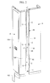
- Fig. 2 is an exploded perspective view of a service panel and a rear panel for fixing the service panel of the outdoor unit.
- An outdoor unit 1 includes a casing 8 which is covered by exterior panels such as a base panel 3 having installation legs 2, a front panel 5 provided with two blowout grilles 4, one at each of upper and lower positions, a rear panel 6 including a part of the right-side face, and an upper panel 7 covering the upper faces of these panels.
- a suction grille is formed in a part of the back face and the left-side face of the casing 8.
- the inside of the casing 8 is partitioned into the heat exchange room side and the machine room side.
- an outdoor heat exchanger, an outdoor air blower, etc. (not shown) are disposed, while on the machine room side, a compressor, a control box, and other outdoor-side devices are disposed.
- a maintenance inspection opening 9 is provided at a corner part of the front panel 5 from the front face to the side face of the casing 8, and a service panel 10 is detachably installed so as to cover the opening 9.
- the service panel 10 is a panel bent such that a front-face side 10A and a side-face side 10B form an L-shaped cross-section, and is provided with a handhole 11 at a roughly central position in the vertical direction of the front-face side 10A.
- the service panel 10 is fixed by having engaging claws 13 engaged with engaging holes 12 provided in opening-side edges 5A and 6A of the front panel 5 and the rear panel 6, at multiple positions at left and right ends (in this example, three positions on each of the left and right ends) of the service panel 10 in the vertical direction, and the service panel 10 is further fixed with screws 14 at one position at each of the upper and lower ends such that the service panel 10 is detachable from the side edges 5A and 6A.
- a side edge portion 6B of a predetermined width which is bent to the side face into a crank shape, and an overlap portion 6C are formed on the opening-side edge 6A of the rear panel 6, and the engaging holes 12 for the engaging claws 13 are provided at even intervals at three positions in the vertical direction of the side edge portion 6B.
- This engaging hole 12 is a vertically elongated slit-like hole, and the upper half of the engaging hole is gradually narrowed into a wedge shape.
- a handhole 15 is also provided on the back side of the rear panel 6 at a position corresponding to the handhole 11 of the service panel 10.
- the engaging claws 13 are provided on the end edge of the side-face side 10B of the service panel 10 at even intervals at three positions in the vertical direction corresponding to the engaging holes 12 provided at three positions of the rear panel 6.
- This engaging claw 13 includes: a base portion protruding in parallel from the end edge of the service panel 10; a claw portion extending upward from the base portion by a predetermined dimension; and a groove portion provided between the claw portion and the end edge and having a thickness equivalent to the plate thickness of the rear panel 6, and the height dimension of the claw portion including the base portion is smaller than the length dimension of the slit-like engaging hole 12 by a predetermined dimension.
- the engaging holes 12 and the engaging claw 13 have the configuration in which the multiple upper and lower engaging claws 13 provided on the service panel 10 are inserted into the multiple engaging holes 12 provided in the rear panel 6, and then the service panel 10 is slid upward by a predetermined dimension (e.g., approximately 10 mm) so as to engage the groove portions having a thickness equivalent to the plate thickness of the rear panel 6 provided in the engaging claws 13 with the upper halves of the engaging holes 12 which are gradually narrowed into a wedge shape.
- the engaging holes 12 and the engaging claws 13 can be thereby engaged without looseness between them.
- the service panel 10 is also provided with engaging claws (not shown) similar to those described above at three positions in the vertical direction corresponding to the part connected with the front panel 6, and provided with similar engaging claws 13 on the side edge of an extended portion 10C toward a lower part of the front panel 6. These engaging claws can be engaged with engaging holes (not shown) similar to those described above provided in the front panel 6 in a similar manner as described above without looseness between them.
- the engaging claws 13 provided at left and right ends of the service panel 10 at multiple positions in the vertical direction are engaged with the engaging holes 12 provided in the front panel 5 and the rear panel 6 at multiple upper and lower positions, and then the service panel is fixed with a screw 14 at one position at each of the upper and lower ends.
- the service panel 10 can be thereby detachably mounted. This service panel 10 can be easily removed by removing the screws 14 at two positions and then sliding the service panel 10 downward to disengage the engaging claws 13 from the engaging holes 12.
- the service panel 10 which is provided at the opening 9 between the front panel 5 and the rear panel 6 of the outdoor unit 1 is detachably installed by the claw fixing method. Therefore, rainwater can seep through the gap of the engaging hole 12, with which the engaging claw 13 is engaged, to the machine room, and there is a possibility of spattering of this rainwater on the control box or the electrical components disposed inside the machine room. The following configuration has been adopted to prevent this situation.
- the engaging holes 12 are provided in the side edge portion 6B of the opening-side edge 6A of the rear panel 6 at three positions in the vertical direction.
- a gutter member 16 extending in the vertical direction is provided so as to cover the back side of these multiple engaging holes 12, and is fixed with screws 17 to the overlap portion 6C of the rear panel 6 at multiple positions in the vertical direction.
- This gutter member 16 can collect the rainwater seeping through the engaging holes 12 so as not to directly spatter toward the inside of the machine room, and cause the rainwater to flow downward along the gutter member 16 and drain it at a lower position where the rainwater is at least unlikely to spatter on the internal parts susceptible to water seepage.
- the gutter member 16 is a steel plate formed into an L-shape or a resin material formed into an L-shape, and covers the back side of the multiple engaging holes 12 with a short side 16A of the L-shape, and is fixed with screws with its long side 16B overlapping the overlap portion 6C of the rear panel 6. In this way, a space 18 of an appropriate size and shape which is shielded from the inside of the machine room is formed on the back side of the multiple engaging holes 12, and the gutter member serves as a passage which the rainwater seeping into the space 18 flows downward through.
- gutter member 16 provided on the back side of the engaging holes 12 of the rear panel 6 has been described above, needless to say, the gutter member may be as necessary provided on the back side of the engaging holes (not shown) of the front panel 5 in a similar manner.
- the service panel 10 of the outdoor unit 1 is attached and detached for maintenance inspection service of the control box and other outdoor-side devices disposed on the machine room side inside the casing 8, and by adopting the claw fixing method, the number of positions fixed with screws is minimized and the serviceability is improved.
- the gutter member 16 which extends in the vertical direction and covers the back side of the multiple engaging holes 12 is provided on the back side of the opening-side edges 6A or 5A of the rear panel 6 or the front panel 5 in which the multiple engaging holes 12 are provided, so that the water seeping through the engaging holes 12 is caused to flow down along the gutter member 16 and the water can be drained to the inside or the outside of the casing 8 at a lower position where the water is at least unlikely to spatter on the internal parts such as electrical components susceptible to water seepage.
- the waterproofing measure requires only the provision of one gutter member 16 which extends across the multiple upper and lower engaging holes 12 in the vertical direction on the back side of these multiple engaging holes 12, it is possible to simplify the waterproof structure and facilitate its assembly work to realize an inexpensive permanent waterproofing measure.
- the gutter member 16 is a member which forms the space 18 of any shape and size on the back side of the engaging holes 12 which allows the seeping water to flow down, it is possible to cause the rainwater seeping through the multiple engaging holes 12 to flow downward through the space 18 of any shape and size formed by the gutter member 16, and drain the water to the inside or the outside of the casing 8 from the lower end of the gutter member.
- the shape and the size of the space 18 formed by the gutter member 16 can be simple and small, just enough to allow minute amounts of rainwater seeping through the multiple engaging holes 12 to flow down through the space.
- the configuration of the gutter member 16 itself can be made simple and inexpensive.
- the gutter member 16 is made of a steel plate or a resin plate. Accordingly, unlike the configuration in which the gap of the engaging hole 12 is blocked by attaching an insulation sheet, there is no need to worry about peeling of the bonding surface or aged deterioration of the gutter member itself, etc. Thus, a permanent waterproofing measure can be provided, and the problems such as the risk of water seepage increasing over time can also be solved.
- the present invention is not limited to the inventions according to the above-described embodiments, but can be appropriately changed without departing from the scope of the present invention.
- the example with the engaging claws 13 and the engaging holes 12 provided at the left and right ends at three positions in the vertical direction has been described; however, the numbers of the engaging claws 13 and the engaging holes 12 may be appropriately increased or decreased according to the size, etc. of the service panel 10.
- the example where the maintenance inspection opening 9 is provided at a corner part of the front panel 5 from the front face to the side face of the casing 8, and the service panel 10 with an L-shaped cross-section is detachably installed at the opening 9 has been described.
- the position of the opening 9 does not have to be the corner part, and accordingly the service panel 10 does not have to be L-shaped in cross-section.
- the opening 9 may be provided at a different position and the service panel 10 may be formed into a shape corresponding to the opening.
Landscapes
- Engineering & Computer Science (AREA)
- Chemical & Material Sciences (AREA)
- Combustion & Propulsion (AREA)
- Mechanical Engineering (AREA)
- General Engineering & Computer Science (AREA)
- Other Air-Conditioning Systems (AREA)
Abstract
Description
- The present invention relates to an air conditioner outdoor unit with a service panel detachably attached to a maintenance inspection opening provided in the casing.
- There are known air conditioner outdoor units, in which a maintenance inspection opening is provided on one side of exterior panels of the casing which faces a machine room for maintenance and inspection of a compressor, a control box, and other outdoor-side devices installed in the machine room inside the casing, and a service panel is detachably attached to the opening. This service panel commonly has a configuration in which multiple engaging claws provided on the service panel are engaged with engaging holes provided in the casing panel, and then the service panel is fixed with screws at one or two positions so as to be detachable from the casing.
- Specific examples of this configuration are shown in
PTL 1 andPTL 2.PTL 1 discloses a configuration in which engaging claws provided on a service panel are engaged with engaging holes provided at multiple positions of a back panel, and then the service panel is fixed at one position with a fixing screw to the back panel so as to be detachable.PTL 2 discloses a configuration in which engaging holes are provided at multiple upper and lower positions of side edge flanges of a front panel and a side panel, and while engaging claws provided at corresponding multiple positions of a service panel are inserted into the respective engaging holes, the service panel is moved upward in two steps to engage upper ends of the engaging claws with upper end edges of the respective engaging holes, and the service panel is detachably held to the casing at this position through a fixing means. -
- {PTL 1}
The Publication of Japanese Patent No.4559326 - {PTL 2}
Japanese Unexamined Patent Application, Publication No.2012-7777 - As described above, the service panel fixed by the claw fixing method can be more efficiently attached and detached compared with a service panel entirely fixed with screws. However, when the claw fixing method is used, as the engaging hole has to be larger than the engaging claw, rainwater can seep through the gap of the engaging hole after the service panel is mounted. Especially the machine room, which communicates with a heat exchanger room and is at a negative pressure due to the suction action of the fan, is prone to seepage of rainwater through the engaging hole, and there is a concern that this rainwater may spatter on the electrical components susceptible to water seepage and cause troubles such as malfunction and control failure.
- In order to prevent water seepage through the claw engaging hole, each hole is provided with a waterproofing measure such as attaching an insulation sheet to the engaging hole to block the gap. However, not only do the man-hour and the cost increase as the number of the holes increases, but also the waterproofing measure of attaching an insulation sheet cannot be a permanent measure because of problems such as peeling of the bonding surface and a high likelihood of deterioration of the insulation sheet, and involves the risk of water seepage which increases in proportion to an increase in the number of the holes.
- The present invention has been made in view of these circumstances, and aims to provide an air conditioner outdoor unit in which a service panel fixed by the claw fixing method is provided with a permanent waterproofing measure which, even when rainwater seeps through the engaging hole, can treat the rainwater without affecting the internal parts and which can be realized in a simple and inexpensive configuration.
- In order to solve the above problems, an air conditioner outdoor unit of the present invention has adopted the following solutions:
- According to the present invention, there is provided an air conditioner outdoor unit, in which a maintenance inspection opening is provided on one side of exterior panels of the casing, and a service panel is detachably attached to the opening by having engaging claws engaged with multiple upper and lower engaging holes provided in an opening-side edge of the exterior panel, wherein a gutter member which extends in the vertical direction and covers the back side of the multiple engaging holes is provided on the back side of the opening-side edge in which the multiple engaging holes are provided, so that water seeping through the engaging holes is caused to flow down along the gutter member and the water can be drained at a lower position where the water is at least unlikely to spatter on the internal parts susceptible to water seepage.
- According to this configuration, although rainwater can seep through the claw engaging hole since the service panel is fixed by the claw fixing method which allows efficient attaching/detaching of the service panel, it is possible to receive the rainwater, even if it seeps, by the gutter member, which extends in the vertical direction and provided on the back side of the engaging hole, and cause the water flow downward along the gutter member and drain it to the inside or the outside of the casing at a lower position where the water is unlikely to spatter on the electrical components, etc. susceptible to water seepage. Thus, it is possible to prevent the situation where the water seeping through the engaging holes spatters on the electrical components, etc. susceptible to water seepage, and to solve the troubles arising from this situation. In addition, since the waterproofing measure requires only the provision of one gutter member which extends across the multiple upper and lower engaging holes in the vertical direction on the back side of these engaging holes, it is possible to simplify the waterproof structure and facilitate its assembly work, and to realize an inexpensive permanent waterproofing measure.
- In the above-described air conditioner outdoor unit, the gutter member may be a member which forms a space of any shape and size on the back side of the engaging holes which allows the seeping water to flow down.
- According to this configuration, it is possible to cause the rainwater seeping through the multiple engaging holes to flow downward through the space of any shape and size formed by the gutter member, and drain the rainwater to the inside or the outside of the casing from the lower end of the gutter member. In addition, the shape and the size of the space formed by the gutter member can be simple and small, just enough to allow minute amounts of rainwater seeping through the multiple engaging holes to flow down through the space. Thus, the configuration of the gutter member itself can be made simple and inexpensive.
- In one of the above-described air conditioner outdoor units, the gutter member may be made of a steel plate or a resin plate.
- According to this configuration, unlike the case of the insulation sheet, there is no need to worry about peeling of the bonding surface or aged deterioration of the gutter member itself, etc. Thus, a permanent waterproofing measure can be provided, and the problems such as the risk of water seepage increasing over time can also be solved.
- In one of the above-described air conditioner outdoor units, the gutter member may be extended to a position immediately above a drain pan which is formed on a bottom surface of the casing.
- According to this configuration, the rainwater seeping through the multiple engaging holes can be guided by the gutter member to above the drain pan and drained. Thus, it is possible to reliably prevent the rainwater seeping through the multiple engaging holes from spattering on the internal parts or on the outside of the casing and to properly treat the rainwater.
- In one of the above-described air conditioner outdoor units, the lower end of the gutter member may be closed by a closing member at a position below the engaging hole located at a lowermost position so that the seeping water flowing down is drained from the engaging hole located at the lowermost position.
- According to this configuration, it is possible to prevent the rainwater from spattering on the electrical components susceptible to water seepage, by causing the rainwater seeping through the engaging holes located at upper positions to flow along the gutter member down to the engaging hole located at the lowermost position, and collecting the rainwater on the closing member which closes the lower end of the gutter member, and draining the rainwater from the closing member through the engaging hole located at the lowermost position to the inside or the outside of the casing. In addition, it is possible to suppress the seepage of rainwater through the engaging hole by closing the lower end of the gutter member so as to suppress generation of a negative pressure in the internal space of the gutter member. In this way, it is possible to minimize the area where the gutter member is provided and make the gutter member compact and inexpensive, as well as to increase the waterproofing effect.
- Further, in the above-described air conditioner outdoor unit, the closing member may be of a closed-cell foamed resin material.
- According to this configuration, it is possible to close the lower end of the gutter member without leaving a gap, as well as to prevent water absorption by the closing member itself. Thus, the effectiveness of closing the lower end of the gutter member can be improved, and deterioration of the closing member due to water absorption can be prevented.
- According to the present invention, although rainwater can seep through the claw engaging hole since the service panel is fixed by the claw fixing method which allows efficient attaching/detaching of the service panel, it is possible to receive the rainwater, even if it seeps, by the gutter member, which extends in the vertical direction and is provided on the back side of the engaging hole, and cause the water to flow downward along the gutter member and drain it to the inside or the outside of the casing at a lower position where the water is unlikely to spatter on the electrical components, etc. susceptible to water seepage. Thus, it is possible to prevent the situation where the water seeping through the engaging holes spatters on the electrical components, etc. susceptible to water seepage, and to solve the troubles arising from this situation. In addition, since the waterproofing measure requires only the provision of one gutter member which extends across the multiple upper and lower engaging holes in the vertical direction on the back side of these engaging holes, it is possible to simplify the waterproof structure and facilitate its assembly work to realize an inexpensive permanent waterproofing measure.
-
- {
Fig. 1 }
Fig. 1 is a perspective view of an air conditioner outdoor unit according to one embodiment of the present invention. - {
Fig. 2 }
Fig. 2 is an exploded perspective view of a service panel and a rear panel for fixing the service panel provided in the outdoor unit. - {
Fig. 3 }
Fig. 3 is a perspective view of the back side of the rear panel shown inFig. 2 . - {
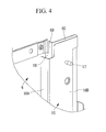
Fig. 4 }
Fig. 4 is an enlarged view of an upper end portion of the rear panel shown inFig. 3 . - {
Fig. 5 }
Fig. 5 is a partially enlarged view from the direction of the arrow A of the rear panel shown inFig. 3 . - {
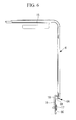
Fig. 6 }
Fig. 6 is a plan view from above of the rear panel shown inFig. 5 . - In the following, one embodiment of the present invention will be described with reference to
Fig. 1 to Fig. 6 . -
Fig. 1 is a perspective view of an air conditioner outdoor unit according to the one embodiment of the present invention, andFig. 2 is an exploded perspective view of a service panel and a rear panel for fixing the service panel of the outdoor unit. - An
outdoor unit 1 includes acasing 8 which is covered by exterior panels such as abase panel 3 havinginstallation legs 2, afront panel 5 provided with twoblowout grilles 4, one at each of upper and lower positions, arear panel 6 including a part of the right-side face, and anupper panel 7 covering the upper faces of these panels. A suction grille is formed in a part of the back face and the left-side face of thecasing 8. - The inside of the
casing 8 is partitioned into the heat exchange room side and the machine room side. On the heat exchange room side, an outdoor heat exchanger, an outdoor air blower, etc. (not shown) are disposed, while on the machine room side, a compressor, a control box, and other outdoor-side devices are disposed. For maintenance and inspection of the outdoor-side devices disposed on the machine room side, amaintenance inspection opening 9 is provided at a corner part of thefront panel 5 from the front face to the side face of thecasing 8, and aservice panel 10 is detachably installed so as to cover theopening 9. - As shown in
Fig. 2 , theservice panel 10 is a panel bent such that a front-face side 10A and a side-face side 10B form an L-shaped cross-section, and is provided with a handhole 11 at a roughly central position in the vertical direction of the front-face side 10A. Theservice panel 10 is fixed by having engagingclaws 13 engaged with engagingholes 12 provided in opening-side edges front panel 5 and therear panel 6, at multiple positions at left and right ends (in this example, three positions on each of the left and right ends) of theservice panel 10 in the vertical direction, and theservice panel 10 is further fixed withscrews 14 at one position at each of the upper and lower ends such that theservice panel 10 is detachable from the side edges 5A and 6A. - This claw fixing structure will be described in more detail with reference to the connection part between the
service panel 10 and therear panel 6 shown inFig. 2 . - A
side edge portion 6B of a predetermined width which is bent to the side face into a crank shape, and anoverlap portion 6C are formed on the opening-side edge 6A of therear panel 6, and the engagingholes 12 for the engagingclaws 13 are provided at even intervals at three positions in the vertical direction of theside edge portion 6B. This engaginghole 12 is a vertically elongated slit-like hole, and the upper half of the engaging hole is gradually narrowed into a wedge shape. Ahandhole 15 is also provided on the back side of therear panel 6 at a position corresponding to thehandhole 11 of theservice panel 10. - On the other hand, the engaging
claws 13 are provided on the end edge of the side-face side 10B of theservice panel 10 at even intervals at three positions in the vertical direction corresponding to the engagingholes 12 provided at three positions of therear panel 6. This engagingclaw 13 includes: a base portion protruding in parallel from the end edge of theservice panel 10; a claw portion extending upward from the base portion by a predetermined dimension; and a groove portion provided between the claw portion and the end edge and having a thickness equivalent to the plate thickness of therear panel 6, and the height dimension of the claw portion including the base portion is smaller than the length dimension of the slit-likeengaging hole 12 by a predetermined dimension. - The engaging
holes 12 and the engagingclaw 13 have the configuration in which the multiple upper and lower engagingclaws 13 provided on theservice panel 10 are inserted into the multiple engagingholes 12 provided in therear panel 6, and then theservice panel 10 is slid upward by a predetermined dimension (e.g., approximately 10 mm) so as to engage the groove portions having a thickness equivalent to the plate thickness of therear panel 6 provided in the engagingclaws 13 with the upper halves of the engagingholes 12 which are gradually narrowed into a wedge shape. The engagingholes 12 and the engagingclaws 13 can be thereby engaged without looseness between them. - The
service panel 10 is also provided with engaging claws (not shown) similar to those described above at three positions in the vertical direction corresponding to the part connected with thefront panel 6, and provided with similarengaging claws 13 on the side edge of anextended portion 10C toward a lower part of thefront panel 6. These engaging claws can be engaged with engaging holes (not shown) similar to those described above provided in thefront panel 6 in a similar manner as described above without looseness between them. - The engaging
claws 13 provided at left and right ends of theservice panel 10 at multiple positions in the vertical direction are engaged with the engagingholes 12 provided in thefront panel 5 and therear panel 6 at multiple upper and lower positions, and then the service panel is fixed with ascrew 14 at one position at each of the upper and lower ends. Theservice panel 10 can be thereby detachably mounted. Thisservice panel 10 can be easily removed by removing thescrews 14 at two positions and then sliding theservice panel 10 downward to disengage the engagingclaws 13 from the engaging holes 12. - In this embodiment, the
service panel 10 which is provided at theopening 9 between thefront panel 5 and therear panel 6 of theoutdoor unit 1 is detachably installed by the claw fixing method. Therefore, rainwater can seep through the gap of the engaginghole 12, with which the engagingclaw 13 is engaged, to the machine room, and there is a possibility of spattering of this rainwater on the control box or the electrical components disposed inside the machine room. The following configuration has been adopted to prevent this situation. - The engaging
holes 12 are provided in theside edge portion 6B of the opening-side edge 6A of therear panel 6 at three positions in the vertical direction. Agutter member 16 extending in the vertical direction is provided so as to cover the back side of these multiple engagingholes 12, and is fixed withscrews 17 to theoverlap portion 6C of therear panel 6 at multiple positions in the vertical direction. Thisgutter member 16 can collect the rainwater seeping through the engagingholes 12 so as not to directly spatter toward the inside of the machine room, and cause the rainwater to flow downward along thegutter member 16 and drain it at a lower position where the rainwater is at least unlikely to spatter on the internal parts susceptible to water seepage. - The
gutter member 16 is a steel plate formed into an L-shape or a resin material formed into an L-shape, and covers the back side of the multiple engagingholes 12 with ashort side 16A of the L-shape, and is fixed with screws with itslong side 16B overlapping theoverlap portion 6C of therear panel 6. In this way, aspace 18 of an appropriate size and shape which is shielded from the inside of the machine room is formed on the back side of the multiple engagingholes 12, and the gutter member serves as a passage which the rainwater seeping into thespace 18 flows downward through. - While the example of the
gutter member 16 provided on the back side of the engagingholes 12 of therear panel 6 has been described above, needless to say, the gutter member may be as necessary provided on the back side of the engaging holes (not shown) of thefront panel 5 in a similar manner. - According to this embodiment, the following advantages can be obtained due to the configuration described above.
- The
service panel 10 of theoutdoor unit 1 is attached and detached for maintenance inspection service of the control box and other outdoor-side devices disposed on the machine room side inside thecasing 8, and by adopting the claw fixing method, the number of positions fixed with screws is minimized and the serviceability is improved. - When the
service panel 10 is thus installed by the claw fixing method, during rainy weather, etc., rainwater can seep through the gap of the engagingholes 12 of therear panel 6 or thefront panel 5 with which the engagingclaws 13 of theservice panel 10 are engaged. In particular, since the machine room is at a negative pressure due to the suction action of the outdoor air blower provided on the heat exchange room side, the rainwater flowing on the panel surface is likely to be suctioned through the engaginghole 12 and seep into the machine room. - In this embodiment, therefore, the
gutter member 16 which extends in the vertical direction and covers the back side of the multiple engagingholes 12 is provided on the back side of the opening-side edges rear panel 6 or thefront panel 5 in which the multiple engagingholes 12 are provided, so that the water seeping through the engagingholes 12 is caused to flow down along thegutter member 16 and the water can be drained to the inside or the outside of thecasing 8 at a lower position where the water is at least unlikely to spatter on the internal parts such as electrical components susceptible to water seepage. - Thus, it is possible to prevent the situation where the rainwater seeping through the engaging
hole 12 spatters on the electrical components, etc. susceptible to water seepage, and to solve the troubles arising from water seepage such as malfunction and control failure. In addition, since the waterproofing measure requires only the provision of onegutter member 16 which extends across the multiple upper and lower engagingholes 12 in the vertical direction on the back side of these multiple engagingholes 12, it is possible to simplify the waterproof structure and facilitate its assembly work to realize an inexpensive permanent waterproofing measure. - Since the
gutter member 16 is a member which forms thespace 18 of any shape and size on the back side of the engagingholes 12 which allows the seeping water to flow down, it is possible to cause the rainwater seeping through the multiple engagingholes 12 to flow downward through thespace 18 of any shape and size formed by thegutter member 16, and drain the water to the inside or the outside of thecasing 8 from the lower end of the gutter member. In addition, the shape and the size of thespace 18 formed by thegutter member 16 can be simple and small, just enough to allow minute amounts of rainwater seeping through the multiple engagingholes 12 to flow down through the space. Thus, the configuration of thegutter member 16 itself can be made simple and inexpensive. - Moreover, in this embodiment, the
gutter member 16 is made of a steel plate or a resin plate. Accordingly, unlike the configuration in which the gap of the engaginghole 12 is blocked by attaching an insulation sheet, there is no need to worry about peeling of the bonding surface or aged deterioration of the gutter member itself, etc. Thus, a permanent waterproofing measure can be provided, and the problems such as the risk of water seepage increasing over time can also be solved. -
- (1) In the above-described embodiment, the rainwater flowing down along the
gutter member 16 is drained to the inside or the outside of thecasing 8 at a lower position where the rainwater is unlikely to spatter on the internal parts such as electrical components susceptible to water seepage. However, the lower end of thegutter member 16 may be extended to a position immediately above a drain pan which is formed on the bottom surface of thecasing 8.
Thus, by extending thegutter member 16 to a position immediately above the drain pan, the rainwater seeping through the multiple engagingholes 12 can be guided by thegutter member 16 to above the drain pan and drained. Therefore, it is possible to reliably prevent the rainwater seeping through the multiple engagingholes 12 from spattering on the internal parts or on the outside of thecasing 8, and to properly treat the rainwater. - (2) The lower end of the
gutter member 16 may be closed by a closing member at a position below the engaginghole 12 located at a lowermost position so that the seeping water flowing down along thegutter member 16 is drained from the engaginghole 12 located at the lowermost position.
The rainwater can be prevented from spattering on the electrical components susceptible to water seepage also by this configuration which causes the rainwater seeping through the engagingholes 12 located at upper positions to flow along thegutter member 16 down to the engaginghole 12 located at the lowermost position, and collects the rainwater on the closing member which closes the lower end of thegutter member 16, and drains the rainwater from the closing member through the engaginghole 12 located at the lowermost position to the inside or the outside of thecasing 8.
In this case, it is possible to suppress the seepage of rainwater through the engaginghole 12 by closing the lower end of thegutter member 16 with the closing member so as to suppress generation of a negative pressure in theinternal space 18 of thegutter member 16. In this way, it is possible to minimize the area where thegutter member 16 is provided and make thegutter member 16 compact and inexpensive, as well as to increase the waterproofing effect. - (3) Moreover, the closing member described above in (2) may be constituted of a closed-cell foamed resin material. By using a closed-cell foamed resin material for the closing member, it is possible to close the lower end of the
gutter member 16 without leaving a gap, as well as to prevent water absorption by the closing member itself. Thus, the effectiveness of closing the lower end of thegutter member 16 can be improved, and deterioration of the closing member due to water absorption can be prevented. - (4) While in the above embodiment the
gutter member 16 is a member made of a steel plate or a resin plate formed into an L-shape in cross-section, the shape of the gutter member is not limited to the L-shaped cross-section; as long as it can form thespace 18 of an appropriate size and shape on the back side of the engagingholes 12 which allows the seeping water to flow down, a member of any shape or material can be used. For example, other than a rigid member, a member having flexibility may of course be used. - The present invention is not limited to the inventions according to the above-described embodiments, but can be appropriately changed without departing from the scope of the present invention. For example, in the above-described embodiment, the example with the engaging
claws 13 and the engagingholes 12 provided at the left and right ends at three positions in the vertical direction has been described; however, the numbers of the engagingclaws 13 and the engagingholes 12 may be appropriately increased or decreased according to the size, etc. of theservice panel 10. - Moreover, in the above-described embodiments, the example where the
maintenance inspection opening 9 is provided at a corner part of thefront panel 5 from the front face to the side face of thecasing 8, and theservice panel 10 with an L-shaped cross-section is detachably installed at theopening 9 has been described. However, the position of theopening 9 does not have to be the corner part, and accordingly theservice panel 10 does not have to be L-shaped in cross-section. Needless to say, theopening 9 may be provided at a different position and theservice panel 10 may be formed into a shape corresponding to the opening. -
- 1
- Outdoor unit
- 5
- Front panel (exterior panel)
- 5A
- Opening-side edge
- 6
- Rear panel (exterior panel)
- 6A
- Opening-side edge
- 8
- Casing
- 9
- Maintenance inspection opening
- 10
- Service panel
- 12
- Engaging hole
- 13
- Engaging claw
- 16
- Gutter member
- 18
- Space
Claims (6)
- An air conditioner outdoor unit (1), in which a maintenance inspection opening (9) is provided on one side of exterior panels (5, 6) of a casing (8), and a service panel (10) is detachably attached to the opening (9) by having engaging claws (13) engaged with multiple upper and lower engaging holes (12) provided in an opening-side edge (5A, 6A) of the exterior panel (5, 6), characterized in that
a gutter member (16) which extends in the vertical direction and covers a back side of the multiple engaging holes (12) is provided on a back side of the opening-side edge (5A, 6A) in which the multiple engaging holes (12) are provided, so that water seeping through the engaging holes (12) is caused to flow down along the gutter member (16) and the water can be drained at a lower position where the water is at least unlikely to spatter on internal parts susceptible to water seepage. - The air conditioner outdoor unit (1) according to claim 1, wherein the gutter member (16) is a member which forms a space (18) of any shape and size on the back side of the engaging holes (12) which allows the seeping water to flow down.
- The air conditioner outdoor unit (1) according to claim 1 or 2, wherein the gutter member (16) is made of a steel plate or a resin plate.
- The air conditioner outdoor unit (1) according to any one of claims 1 to 3, wherein the gutter member (16) is extended to a position immediately above a drain pan which is formed on a bottom surface of the casing (8).
- The air conditioner outdoor unit according to any one of claims 1 to 3, wherein the lower end of the gutter member (16) is closed by a closing member at a position below the engaging hole (12) located at a lowermost position so that the seeping water flowing down is drained from the engaging hole (12) located at the lowermost position.
- The air conditioner outdoor unit (1) according to claim 5, wherein the closing member is of a closed-cell foamed resin material.
Applications Claiming Priority (1)
| Application Number | Priority Date | Filing Date | Title |
|---|---|---|---|
| JP2013144516A JP5968271B2 (en) | 2013-07-10 | 2013-07-10 | Air conditioner outdoor unit |
Publications (1)
| Publication Number | Publication Date |
|---|---|
| EP2840326A1 true EP2840326A1 (en) | 2015-02-25 |
Family
ID=51167654
Family Applications (1)
| Application Number | Title | Priority Date | Filing Date |
|---|---|---|---|
| EP14175373.1A Withdrawn EP2840326A1 (en) | 2013-07-10 | 2014-07-02 | Air conditioner outdoor unit |
Country Status (2)
| Country | Link |
|---|---|
| EP (1) | EP2840326A1 (en) |
| JP (1) | JP5968271B2 (en) |
Cited By (5)
| Publication number | Priority date | Publication date | Assignee | Title |
|---|---|---|---|---|
| EP3203161A1 (en) * | 2016-02-05 | 2017-08-09 | Mitsubishi Heavy Industries Thermal Systems, Ltd. | Air conditioning apparatus |
| WO2018030892A1 (en) * | 2016-08-12 | 2018-02-15 | Daikin Research & Development Malaysia Sdn. Bhd. | Service panel of an air conditioner |
| US11428421B2 (en) | 2017-07-31 | 2022-08-30 | Daikin Industries, Ltd. | Outdoor unit of refrigeration apparatus |
| EP4102143A1 (en) * | 2021-06-07 | 2022-12-14 | Panasonic Intellectual Property Management Co., Ltd. | Heat pump heat source device |
| WO2025086339A1 (en) * | 2023-10-27 | 2025-05-01 | 宁波奥克斯电气股份有限公司 | Integral heat pump |
Families Citing this family (4)
| Publication number | Priority date | Publication date | Assignee | Title |
|---|---|---|---|---|
| CN105972716B (en) * | 2016-06-23 | 2020-09-04 | 珠海格力电器股份有限公司 | Sheet metal part connecting structure and air conditioner outdoor unit |
| CN108592247A (en) * | 2018-04-28 | 2018-09-28 | 广东美的暖通设备有限公司 | Air-conditioner outdoor unit and air conditioner with it |
| WO2020012527A1 (en) * | 2018-07-09 | 2020-01-16 | 三菱電機株式会社 | Outdoor unit for air-conditioning device |
| US12264827B2 (en) * | 2020-02-26 | 2025-04-01 | Mitsubishi Electric Corporation | Outdoor unit of air-conditioning apparatus |
Citations (6)
| Publication number | Priority date | Publication date | Assignee | Title |
|---|---|---|---|---|
| JPH09145096A (en) * | 1995-11-24 | 1997-06-06 | Matsushita Electric Ind Co Ltd | Air conditioner |
| JP2007247984A (en) * | 2006-03-16 | 2007-09-27 | Matsushita Electric Ind Co Ltd | Air conditioner outdoor unit |
| JP2009250459A (en) * | 2008-04-02 | 2009-10-29 | Panasonic Corp | Outdoor unit of air conditioner |
| JP4559326B2 (en) | 2005-09-13 | 2010-10-06 | 三菱電機株式会社 | Air conditioner outdoor unit |
| JP2012007777A (en) | 2010-06-23 | 2012-01-12 | Fujitsu General Ltd | Outdoor unit of air conditioner |
| JP2013133969A (en) * | 2011-12-26 | 2013-07-08 | Panasonic Corp | Outdoor unit of air conditioner |
Family Cites Families (6)
| Publication number | Priority date | Publication date | Assignee | Title |
|---|---|---|---|---|
| US3915530A (en) * | 1974-09-18 | 1975-10-28 | Westinghouse Electric Corp | Insertable filler arrangement for reducing opening size |
| JPH08178360A (en) * | 1994-12-20 | 1996-07-12 | Fujitsu General Ltd | Air conditioner outdoor unit |
| US6354936B1 (en) * | 1998-08-10 | 2002-03-12 | Lg Electronics Inc. | Opening-closing structure of an inlet grille in an air conditioner |
| JP3019850B1 (en) * | 1998-11-13 | 2000-03-13 | ダイキン工業株式会社 | Outdoor unit of air conditioner |
| WO2007086640A2 (en) * | 2006-01-26 | 2007-08-02 | Lg Electronics Inc. | Indoor unit of air conditioner |
| JP5058004B2 (en) * | 2008-01-28 | 2012-10-24 | 三菱電機株式会社 | Outdoor unit and air conditioner equipped with the same |
-
2013
- 2013-07-10 JP JP2013144516A patent/JP5968271B2/en active Active
-
2014
- 2014-07-02 EP EP14175373.1A patent/EP2840326A1/en not_active Withdrawn
Patent Citations (6)
| Publication number | Priority date | Publication date | Assignee | Title |
|---|---|---|---|---|
| JPH09145096A (en) * | 1995-11-24 | 1997-06-06 | Matsushita Electric Ind Co Ltd | Air conditioner |
| JP4559326B2 (en) | 2005-09-13 | 2010-10-06 | 三菱電機株式会社 | Air conditioner outdoor unit |
| JP2007247984A (en) * | 2006-03-16 | 2007-09-27 | Matsushita Electric Ind Co Ltd | Air conditioner outdoor unit |
| JP2009250459A (en) * | 2008-04-02 | 2009-10-29 | Panasonic Corp | Outdoor unit of air conditioner |
| JP2012007777A (en) | 2010-06-23 | 2012-01-12 | Fujitsu General Ltd | Outdoor unit of air conditioner |
| JP2013133969A (en) * | 2011-12-26 | 2013-07-08 | Panasonic Corp | Outdoor unit of air conditioner |
Cited By (9)
| Publication number | Priority date | Publication date | Assignee | Title |
|---|---|---|---|---|
| EP3203161A1 (en) * | 2016-02-05 | 2017-08-09 | Mitsubishi Heavy Industries Thermal Systems, Ltd. | Air conditioning apparatus |
| AU2017200655B2 (en) * | 2016-02-05 | 2018-04-19 | Mitsubishi Heavy Industries Thermal Systems, Ltd. | Air conditioning apparatus |
| WO2018030892A1 (en) * | 2016-08-12 | 2018-02-15 | Daikin Research & Development Malaysia Sdn. Bhd. | Service panel of an air conditioner |
| CN109564017A (en) * | 2016-08-12 | 2019-04-02 | 大金研发马来西亚私人有限公司 | Air-conditioning power distribution panels |
| CN109564017B (en) * | 2016-08-12 | 2021-04-06 | 大金研发马来西亚私人有限公司 | Air conditioner distribution panel |
| US11428421B2 (en) | 2017-07-31 | 2022-08-30 | Daikin Industries, Ltd. | Outdoor unit of refrigeration apparatus |
| EP3663659B1 (en) * | 2017-07-31 | 2022-12-14 | Daikin Industries, Ltd. | Outdoor unit for refrigeration device |
| EP4102143A1 (en) * | 2021-06-07 | 2022-12-14 | Panasonic Intellectual Property Management Co., Ltd. | Heat pump heat source device |
| WO2025086339A1 (en) * | 2023-10-27 | 2025-05-01 | 宁波奥克斯电气股份有限公司 | Integral heat pump |
Also Published As
| Publication number | Publication date |
|---|---|
| JP5968271B2 (en) | 2016-08-10 |
| JP2015017740A (en) | 2015-01-29 |
Similar Documents
| Publication | Publication Date | Title |
|---|---|---|
| JP5968271B2 (en) | Air conditioner outdoor unit | |
| CN103946640B (en) | Embedded air conditioner | |
| JP6678738B2 (en) | Air conditioner indoor unit | |
| EP2716983A2 (en) | Air conditioner outdoor unit | |
| JP5556676B2 (en) | Air conditioner outdoor unit | |
| EP2716982A2 (en) | Air conditioner outdoor unit | |
| US11009241B2 (en) | Heat source unit for refrigeration apparatus | |
| JP2015017740A5 (en) | ||
| CN108765770B (en) | Self-service cabinet body and self-service cabinet with anti-water seepage function | |
| CN110062548A (en) | A kind of electric-controlled box and air conditioner | |
| CN108369025B (en) | Indoor unit of air conditioner | |
| CN210399241U (en) | Waterproof electric control box and air conditioning system | |
| CN108703541B (en) | Fresh cabinet body and fresh cabinet | |
| CN108703542B (en) | Self-collection cabinet and self-collection cabinet | |
| CN108711235B (en) | Fresh food self-pickup cabinet and fresh food self-pickup cabinet | |
| CN108800707B (en) | Refrigeration equipment cabinet and refrigeration equipment | |
| CN108826809B (en) | Press top refrigeration equipment | |
| JP3515206B2 (en) | Refrigerator electrical box | |
| WO2017022087A1 (en) | Ventilation fan | |
| CN223437290U (en) | Computer room air conditioner | |
| EP4306868A1 (en) | Outdoor unit | |
| CN108713905B (en) | Cabinets and express cabinets with waterproof function | |
| CN105102901B (en) | Air conditioner | |
| JP5682424B2 (en) | Heat exchanger | |
| EP3029392A1 (en) | Stabilizing and sealing arrangement |
Legal Events
| Date | Code | Title | Description |
|---|---|---|---|
| PUAI | Public reference made under article 153(3) epc to a published international application that has entered the european phase |
Free format text: ORIGINAL CODE: 0009012 |
|
| 17P | Request for examination filed |
Effective date: 20140702 |
|
| AK | Designated contracting states |
Kind code of ref document: A1 Designated state(s): AL AT BE BG CH CY CZ DE DK EE ES FI FR GB GR HR HU IE IS IT LI LT LU LV MC MK MT NL NO PL PT RO RS SE SI SK SM TR |
|
| AX | Request for extension of the european patent |
Extension state: BA ME |
|
| R17P | Request for examination filed (corrected) |
Effective date: 20150723 |
|
| RBV | Designated contracting states (corrected) |
Designated state(s): AL AT BE BG CH CY CZ DE DK EE ES FI FR GB GR HR HU IE IS IT LI LT LU LV MC MK MT NL NO PL PT RO RS SE SI SK SM TR |
|
| RAP1 | Party data changed (applicant data changed or rights of an application transferred) |
Owner name: MITSUBISHI HEAVY INDUSTRIES THERMAL SYSTEMS, LTD. |
|
| STAA | Information on the status of an ep patent application or granted ep patent |
Free format text: STATUS: EXAMINATION IS IN PROGRESS |
|
| 17Q | First examination report despatched |
Effective date: 20180914 |
|
| GRAP | Despatch of communication of intention to grant a patent |
Free format text: ORIGINAL CODE: EPIDOSNIGR1 |
|
| STAA | Information on the status of an ep patent application or granted ep patent |
Free format text: STATUS: GRANT OF PATENT IS INTENDED |
|
| INTG | Intention to grant announced |
Effective date: 20200102 |
|
| STAA | Information on the status of an ep patent application or granted ep patent |
Free format text: STATUS: THE APPLICATION IS DEEMED TO BE WITHDRAWN |
|
| 18D | Application deemed to be withdrawn |
Effective date: 20200603 |