EP2840284A1 - Hydraulische Lüftersteuerung - Google Patents
Hydraulische Lüftersteuerung Download PDFInfo
- Publication number
- EP2840284A1 EP2840284A1 EP14002734.3A EP14002734A EP2840284A1 EP 2840284 A1 EP2840284 A1 EP 2840284A1 EP 14002734 A EP14002734 A EP 14002734A EP 2840284 A1 EP2840284 A1 EP 2840284A1
- Authority
- EP
- European Patent Office
- Prior art keywords
- hydraulic
- valve
- pressure relief
- pilot
- pressure
- Prior art date
- Legal status (The legal status is an assumption and is not a legal conclusion. Google has not performed a legal analysis and makes no representation as to the accuracy of the status listed.)
- Granted
Links
Images


Classifications
-
- F—MECHANICAL ENGINEERING; LIGHTING; HEATING; WEAPONS; BLASTING
- F16—ENGINEERING ELEMENTS AND UNITS; GENERAL MEASURES FOR PRODUCING AND MAINTAINING EFFECTIVE FUNCTIONING OF MACHINES OR INSTALLATIONS; THERMAL INSULATION IN GENERAL
- F16H—GEARING
- F16H61/00—Control functions within control units of change-speed- or reversing-gearings for conveying rotary motion ; Control of exclusively fluid gearing, friction gearing, gearings with endless flexible members or other particular types of gearing
- F16H61/38—Control of exclusively fluid gearing
- F16H61/40—Control of exclusively fluid gearing hydrostatic
- F16H61/4035—Control of circuit flow
-
- F—MECHANICAL ENGINEERING; LIGHTING; HEATING; WEAPONS; BLASTING
- F16—ENGINEERING ELEMENTS AND UNITS; GENERAL MEASURES FOR PRODUCING AND MAINTAINING EFFECTIVE FUNCTIONING OF MACHINES OR INSTALLATIONS; THERMAL INSULATION IN GENERAL
- F16H—GEARING
- F16H61/00—Control functions within control units of change-speed- or reversing-gearings for conveying rotary motion ; Control of exclusively fluid gearing, friction gearing, gearings with endless flexible members or other particular types of gearing
- F16H61/38—Control of exclusively fluid gearing
- F16H61/40—Control of exclusively fluid gearing hydrostatic
- F16H61/4043—Control of a bypass valve
-
- F—MECHANICAL ENGINEERING; LIGHTING; HEATING; WEAPONS; BLASTING
- F16—ENGINEERING ELEMENTS AND UNITS; GENERAL MEASURES FOR PRODUCING AND MAINTAINING EFFECTIVE FUNCTIONING OF MACHINES OR INSTALLATIONS; THERMAL INSULATION IN GENERAL
- F16H—GEARING
- F16H61/00—Control functions within control units of change-speed- or reversing-gearings for conveying rotary motion ; Control of exclusively fluid gearing, friction gearing, gearings with endless flexible members or other particular types of gearing
- F16H61/38—Control of exclusively fluid gearing
- F16H61/40—Control of exclusively fluid gearing hydrostatic
- F16H61/46—Automatic regulation in accordance with output requirements
- F16H61/47—Automatic regulation in accordance with output requirements for achieving a target output speed
-
- B—PERFORMING OPERATIONS; TRANSPORTING
- B60—VEHICLES IN GENERAL
- B60K—ARRANGEMENT OR MOUNTING OF PROPULSION UNITS OR OF TRANSMISSIONS IN VEHICLES; ARRANGEMENT OR MOUNTING OF PLURAL DIVERSE PRIME-MOVERS IN VEHICLES; AUXILIARY DRIVES FOR VEHICLES; INSTRUMENTATION OR DASHBOARDS FOR VEHICLES; ARRANGEMENTS IN CONNECTION WITH COOLING, AIR INTAKE, GAS EXHAUST OR FUEL SUPPLY OF PROPULSION UNITS IN VEHICLES
- B60K25/00—Auxiliary drives
- B60K25/02—Auxiliary drives directly from an engine shaft
- B60K2025/026—Auxiliary drives directly from an engine shaft by a hydraulic transmission
-
- B—PERFORMING OPERATIONS; TRANSPORTING
- B60—VEHICLES IN GENERAL
- B60W—CONJOINT CONTROL OF VEHICLE SUB-UNITS OF DIFFERENT TYPE OR DIFFERENT FUNCTION; CONTROL SYSTEMS SPECIALLY ADAPTED FOR HYBRID VEHICLES; ROAD VEHICLE DRIVE CONTROL SYSTEMS FOR PURPOSES NOT RELATED TO THE CONTROL OF A PARTICULAR SUB-UNIT
- B60W2510/00—Input parameters relating to a particular sub-units
- B60W2510/10—Change speed gearings
- B60W2510/107—Temperature
-
- B—PERFORMING OPERATIONS; TRANSPORTING
- B60—VEHICLES IN GENERAL
- B60Y—INDEXING SCHEME RELATING TO ASPECTS CROSS-CUTTING VEHICLE TECHNOLOGY
- B60Y2410/00—Constructional features of vehicle sub-units
- B60Y2410/13—Materials or fluids with special properties
- B60Y2410/136—Memory alloys
-
- F—MECHANICAL ENGINEERING; LIGHTING; HEATING; WEAPONS; BLASTING
- F01—MACHINES OR ENGINES IN GENERAL; ENGINE PLANTS IN GENERAL; STEAM ENGINES
- F01P—COOLING OF MACHINES OR ENGINES IN GENERAL; COOLING OF INTERNAL-COMBUSTION ENGINES
- F01P7/00—Controlling of coolant flow
- F01P7/02—Controlling of coolant flow the coolant being cooling-air
- F01P7/04—Controlling of coolant flow the coolant being cooling-air by varying pump speed, e.g. by changing pump-drive gear ratio
- F01P7/044—Controlling of coolant flow the coolant being cooling-air by varying pump speed, e.g. by changing pump-drive gear ratio using hydraulic drives
Definitions
- a hydraulic fan motor has to change its speed depending on an oil temperature.
- the engine should not start as much as possible, and when the oil is warming above a threshold, the engine speed should steadily rise to achieve increasing cooling capacity.
- the fan motor is not running, the oil should be able to flow through a bypass line to a tank with little pressure loss.
- thermo valve has as Verstellaktuator an expansion element, which today mainly commercially available wax elements are used, wherein the expansion element expands from a certain temperature and increases the force on the pilot control of the pressure valve.
- the advantages of the known solution are in the purely thermal fan control, with no sensors or other electrical control technology is necessary. Furthermore, the known solutions build compact and, at least in theory, the solution represents an energy-efficient fan control that provides the cooling capacity as needed.
- only one temperature measuring point is provided, ie only the inlet temperature, that is to say the oil temperature of the hydraulic tank, is used to control the fan speed. This can be a time delay of the Increase in the fan speed bring with rapidly rising oil temperature in the return of the working hydraulics.
- the present invention seeks to provide a hydraulic fan control, while avoiding the disadvantages described above certainly avoids the disadvantages described with certainty.
- This object is achieved by a hydraulic fan control with the features of patent claim 1 or with the features of patent claim 2.
- an energy-efficient fan control is achieved with demand-controlled cooling capacity, which means that the fan speed only increases with increasing oil temperature when a temperature threshold is reached.
- thermocouple can also be preferably placed elsewhere to influence the fan bypass valve.
- the fan control can be designed flexibly to the respective application and the climatic conditions.
- thermocouple on no signs of aging, so that long-term operation is ensured.
- the cooler thermo-bypass valve has the primary task of leading from a downstream circuit, in particular in the form of a working hydraulic, backflowing oil to the tank or the radiator. With cold return oil, the total return flow should be directed back to the tank with little pressure loss. When the oil temperature rises above a certain value, the division of the oil flow begins, so that now a partial amount flows over the cooler. Upon reaching a further temperature threshold, the total return flow flows through the radiator.
- the temperature ranges of the radiator thermal bypass valve and the pilot pressure relief valve may overlap within certain limits.
- the pressure supply device using a constant-displacement hydraulic pump preferably delivers a constant volume flow and the bypass pressure relief valve has a supply orifice, via which a small volume flow through the pilot valve can flow back directly to the tank.
- the actuator of the pilot valve is a compression spring made of a thermal shape memory alloy having a temperature-dependent force-stroke characteristic.
- the hydraulic fan control after the Fig. 1 basically concerns a simplified circuit with thermocouple for the precontrol of the Fan DBs.
- the circuit includes z. T. components according to the prior art and in particular has a fan motor 10, which is designed as a hydraulic motor driven by a pressure medium, in particular in the form of hydraulic oil.
- a fan motor 10 for the supply of the fan motor 10 is a pump 12, in particular in the form of a hydraulic pump, particularly preferably in the form of a constant displacement pump.
- the pump 12 delivers pressure medium from a designated T tank.
- the pump 12 with the associated lines forms the pressure supply device for the hydraulic fan control.
- a cooler thermo-bypass valve designated 14.
- the pertinent radiator thermal bypass valve 14 controls the return of the pressure medium from a working hydraulics (not shown) connected to the fan device, which is connected to the bypass valve 14 via an input port 16. Via a temperature tap 18 and a temperature control element 20, the bypass valve 14 can be brought against the action of a return spring in the individual switching or travel position. Accordingly, on the output side, the bypass valve 14 is connected via an outlet port 22 and a return line to the tank T and connected via a further output port 24 on the input side to a flow cooler 26. On the output side, the cooler 26 is in turn connected to the tank return line to the tank T out. With cold return oil, the valve 14 takes its in the Fig.
- a pressure relief valve 28 is arranged parallel to the main flow direction of the pump 12 at the output, which is connected to the output side of the tank.
- a bypass pressure relief valve 32 is connected to the output side of the pump 12, which has a displaceable against a return spring 34 piston 36, the u.a. arranged a supply orifice 38 in the housing of the pressure relief valve 32 accordingly.
- a fluid-conducting connection between the line branch 30 and the tank T via the inlet orifice 38 may be made.
- a pilot pressure relief valve 40 is arranged with a 42 designated pilot valve seat and a pilot valve setting device 44.
- the aforementioned pilot valve seat is formed of a valve plug having a through hole 46 in Bottom of the valve 32 drives.
- the valve cone is supported via a spring plate on an energy store in the form of a compression spring 48, consisting of a so-called shape memory alloy.
- the compression spring 48 is guided in a pilot chamber 50 of the valve 40, which has a fluid or media-carrying connection 52 to the tank T.
- the pump 12 should deliver a constant volume flow, and via the inlet orifice 38 of the bypass pressure relief valve 32, a small volume flow through the pilot valve flow back to the tank.
- the spring side of the bypass pressure relief valve Relieved 32, and the piston 36 is due to the resulting pressure difference at the inlet orifice 38 in the open position.
- a force is applied to the pilot valve seat 42 upon reaching the activation temperature of the shape memory material for the compression spring 48, and the pressure in the spring chamber with the return spring 34 of the bypass pressure relief valve 32 increases.
- the speed of the fan motor 10 increases.
- the adjustment mechanism 44 shown the open position of the pilot valve seat 42 can be adjusted according to the local conditions.
- bypass valve 32 in total in the closed position, therefore, the fan motor 10 is driven, and in the open position of the bypass pressure relief valve 32 is the fan.
- the relevant temperature and flow values can be exemplified by the Fig. 1 seen.
- the passage opening 56 of the second pilot valve 54 is media-carrying with the spring chamber for a functionally reliable use connected to the return spring 34 of the bypass pressure relief valve 32.
- the pilot valve seat 58 incorporating a further energy accumulator in the form of a compression spring 60 likewise designed with shape memory alloy, controls the passage opening 56 and influences the bypass pressure limiting valve 32 as far as the first pilot pressure relief valve 40.
- the second pilot valve 54 is therefore able to extend the speed control range of the fan motor 10, wherein it experiences via the output line of the radiator 26, the oil outlet temperature for driving.
- the Druckeinstell Switzerland is increased in the spring chamber of the pilot-by-pass valve 32.
- the second pilot pressure relief valve 54 is connected in a bypass line 62 to the radiator 26, and the pilot chamber with the energy storage 60 is connected to the bypass line 62, wherein the input side to the second pilot valve 54 is still a shutter 64 is connected in the bypass line 62.
- the motor 10 of course has fan blades 66 as a fan motor in order to obtain an improved air flow for the cooler 26.
- the pilot pressure is in turn provided by a single pilot valve 40, but this time has two different energy storage with shape memory elements for different temperature ranges.
- the shape memory elements designed as compression springs 48, 60 are arranged concentrically to each other and have the in the Fig. 4 specified different Temperaturan Kunststoff Kunststoffe on.
- Fig. 5 that like the circuit after the Fig. 4 works, is structurally provided to arrange the shape memory springs 48 and 60 in series one behind the other and thus connect in series with each other.
- All solutions according to the FIGS. 4 to 7 include the detection of the tank temperature of the tank T.
- the respective spring formed from said shape memory alloy material, changes its metallographic lattice structure upon activation, that is to say when it exceeds a certain predeterminable temperature.
- the tension of the grid structure changes the length of the spring. If this change in length is hindered, a force builds up. In the cold state, the shape memory alloy spring is accordingly relaxed, and the respective pilot valve seat is opened.
Landscapes
- Engineering & Computer Science (AREA)
- General Engineering & Computer Science (AREA)
- Mechanical Engineering (AREA)
- Fluid-Pressure Circuits (AREA)
- Temperature-Responsive Valves (AREA)
Abstract
Description
- Die Erfindung betrifft eine hydraulische Lüftersteuerung, bestehend aus mindestens
- einem Lüftermotor,
- einer Druckversorgungseinrichtung, insbesondere Hydropumpe, zum Versorgen des Lüftermotors mit einem Druckmedium, insbesondere in Form von Hydrauliköl, und
- einem die Regelung der Lüftermotordrehzahl steuernden Thermoventil.
- Ein hydraulischer Lüftermotor hat in Abhängigkeit von einer Öltemperatur seine Drehzahl zu verändern. Bei kaltem Öl soll der Motor nach Möglichkeit nicht anlaufen und bei sich erwärmendem Öl über einen Schwellenwert hinaus soll die Motordrehzahl zwecks Erreichen einer zunehmenden Kühlleistung stetig ansteigen. Bei nicht laufendem Lüftermotor soll das Öl mit geringem Druckverlust über eine Bypassleitung zu einem Tank abfließen können.
- Um diesen Vorgaben gerecht zu werden, ist es im Stand der Technik bekannt, Steuerungen für einen hydraulischen Lüfter einzusetzen, die über rein thermisch vorgesteuerte Bypass-Druckbegrenzungsventile verfügen. Mithin wird, da die Lüfterdrehzahl abhängig ist vom Druck, in einer Zulaufleitung dieser Druck von einem üblicherweise parallel zum Lüftermotor angeordneten, vorgesteuerten Druckventil eingestellt. Die Regelung der Lüftermotordrehzahl selbst erfolgt über ein im Zulaufbereich des Lüfters angeordnetes Thermoventil, welches ständig von Hydraulikflüssigkeit umströmt wird. Das genannte Thermoventil regelt dabei in Abhängigkeit von der Öltemperatur den Vorsteuerdruck für das Druckventil im Lüftermotor-Bypass.
- Das angesprochene Thermoventil besitzt als Verstellaktuator ein Dehnstoffelement, wobei heute überwiegend kaufübliche Wachselemente zum Einsatz kommen, wobei sich das Dehnstoffelement ab einer gewissen Temperatur ausdehnt und die Kraft auf die Vorsteuerung des Druckventils erhöht. Theoretisch gibt es dabei einen Temperatur-Regelbereich von bis zu 20 Kelvin mit einer unstetigen Kennlinie und das jeweilige Temperatur-Regelniveau ist wählbar abhängig vom eingesetzten Dehnstoffelement. Die Vorteile der dahingehend bekannten Lösung liegen in der rein thermischen Lüftersteuerung, wobei keine Sensorik oder sonstige elektrische Steuerungstechnik notwendig ist. Ferner bauen die bekannten Lösungen kompakt auf und zumindest in der Theorie stellt die Lösung eine energieeffiziente Lüftersteuerung dar, die bedarfsgerecht die Kühlleistung bereitstellt.
- Als Nachteil hat sich jedoch ein schlechtes Proportionalverhalten erwiesen bezogen auf das Dehnstoffelement. Bei einem angegebenen Proportionalbereich von 20 Kelvin läuft der Lüftermotor in der Regel bei kaltem Öl gar nicht; bereits bei Übersteigen eines sehr kleinen Temperaturbereichs läuft der Lüftermotor dann aber mit maximaler Drehzahl. Für den Anwender ist die dahingehende Steuerungscharakteristik regelmäßig unzureichend, da die Lüfterdrehzahl über einen Bereich von mindestens 10°C bis 20°C der Öltemperatur nachfolgen sollte.
- Des Weiteren ist nur eine Temperaturmessstelle vorgesehen, d.h. es wird nur die Zulauftemperatur, sprich die Öltemperatur des Hydrauliktanks zur Regelung der Lüfterdrehzahl verwendet. Dieses kann einen Zeitverzug des Anstiegs der Lüfterdrehzahl mit sich bringen bei rasch ansteigender Öltemperatur im Rücklauf der Arbeitshydraulik.
- Des Weiteren kommt es zu Alterungserscheinungen des Dehnstoffelements (Wachselement), welches zu einer signifikanten Verschlechterung der Hub-und Krafteigenschaften führt. Folglich verschlechtert sich die Lüfterdrehzahlregelung.
- Ausgehend von diesem Stand der Technik liegt der Erfindung die Aufgabe zugrunde, eine hydraulische Lüftersteuerung zu schaffen, die unter Beibehalten der vorstehend genannten Vorteile jedenfalls die beschriebenen Nachteile mit Sicherheit vermeidet. Eine dahingehende Aufgabe löst eine hydraulische Lüftersteuerung mit den Merkmalen des Patentanspruchs 1 oder mit den Merkmalen des Patentanspruchs 2.
- Dadurch, dass gemäß dem kennzeichnenden Teil des Patentanspruchs 1 das Thermoventil einen Energiespeicher, vorzugsweise in Form einer Druckfeder, bestehend aus einer Formgedächtnislegierung, aufweist oder dass die hydraulische Lüftersteuerung weiter bestehend aufgebaut ist aus mindestens
- einem vorzugsweise Kühler-Thermo-Bypassventil, das den Rücklauf des Druckmediums aus einer an die Lüftereinrichtung anschließbaren Arbeitshydraulik steuert,
- einem Bypass-Druckbegrenzungsventil, das den möglichen Fluidfluss zwischen der Druckversorgungseinrichtung und einem Tankanschluss steuert, und
- einem Vorsteuer-Druckbegrenzungsventil für die Vorsteuerung des Bypass-Druckbegrenzungsventils,
- Bypass-Druckbegrenzungsventil an einschlägigen konstruktiven Stellen maßgebend geändert.
- Mit den vorstehend genannten Maßnahmen ist jedenfalls eine energieeffiziente Lüftersteuerung erreicht mit bedarfsgerechter Regelung der Kühlleistung, was bedeutet, dass die Lüfterdrehzahl bei Erreichen eines Temperatur-Schwellenwertes nur mit zunehmender Öltemperatur weiter ansteigt.
- Zur besseren Regelung der Lüfterdrehzahl kann darüber hinaus ein zusätzliches Thermoelement bevorzugt an anderer Stelle platziert werden, um das Lüfter-Bypassventil zu beeinflussen. Dadurch kann flexibel auf die jeweilige Applikation und die klimatischen Bedingungen hin orientiert die Lüftersteuerung gestaltet werden. Des Weiteren weist das Thermoelement keine Alterungserscheinungen auf, so dass lang andauernd ein Betrieb sichergestellt ist.
- Das Kühler-Thermo-Bypassventil hat vorrangig die Aufgabe, das von einem nachgeschalteten Kreislauf, insbesondere in Form einer Arbeitshydraulik, rückfließende Öl zum Tank bzw. zum Kühler zu leiten. Bei kaltem Rücklauföl soll die gesamte Rücklaufmenge mit geringem Druckverlust zurück zum Tank geleitet werden. Bei ansteigender Öltemperatur über einen gewissen Wert hinaus beginnt die Teilung des Ölstroms, so dass nun eine Teilmenge über den Kühler fließt. Bei Erreichen einer weiteren Temperaturschwelle strömt die gesamte Rücklaufmenge über den Kühler. Dabei können sich die Temperaturbereiche des Kühler-Thermo-Bypassventils und die des Vorsteuer-Druckbegrenzungsventils in gewissen Grenzen überschneiden.
- Die Druckversorgungseinrichtung unter Einsatz einer Konstant-Hydropumpe liefert bevorzugt einen konstanten Volumenstrom und das Bypass-Druckbegrenzungsventil besitzt eine Zulaufblende, über die ein kleiner Volumenstrom durch das Vorsteuerventil direkt zum Tank zurückfließen kann. Bei kaltem Tanköl ist die Federseite des Bypass-Druckbegrenzungs-ventils entlastet und der Kolben geht aufgrund der entstehenden Druckdifferenz an der Blende in Öffnungsstellung. Bevorzugt ist dabei der Aktuator des Vorsteuerventils eine Druckfeder aus einer thermischen Formgedächtnislegierung, die eine temperaturabhängige Kraft-Hub-Kennlinie besitzt.
- Bei heißer werdendem Zulauföl von der Pumpe wird bei Erreichen der Aktivierungstemperatur des Formgedächtnismaterials eine Kraft auf den Vorsteuersitz aufgebaut und der Druck im Federraum des Bypass-Druckbegrenzungsventils steigt. Dadurch steigt die Drehzahl des Lüftermotors an, wobei mit einem zusätzlichen Einstellmechanismus die Öffnungsstellung des Vorsteuersitzes eingestellt werden kann.
- Weitere bevorzugte Ausführungsformen der erfindungsgemäßen Lösung sind Gegenstand der sonstigen Unteransprüche. Durch sinnfällige Kombinationen der Merkmalsausgestaltungen nach den Unteransprüchen lassen sich eine Vielzahl von Kombinationen mit Platzierung der Thermoventile an verschiedenen Orten, die nicht alle dargestellt sind, innerhalb der hydraulischen Lüftersteuerung erreichen.
- Im Folgenden wird die erfindungsgemäße hydraulische Lüftersteuerung anhand verschiedener Ausführungsbeispiele nach der Zeichnung näher erläutert. Dabei zeigen in prinzipieller und nicht maßstäblicher Darstellung in der Art hydraulischer Schaltpläne die
- Fig. 1 bis 7
- verschiedene Ausführungsformen der erfindungsgemäßen hydraulischen Lüftersteuerung.
- Die hydraulische Lüftersteuerung nach der
Fig. 1 betrifft dem Grunde nach eine vereinfachte Schaltung mit Thermoelement für die Vorsteuerung des Lüfter-DB's. Die Schaltung beinhaltet z. T. Komponenten nach dem Stand der Technik und weist insbesondere einen Lüftermotor 10 auf, der als Hydromotor ausgebildet von einem Druckmedium, insbesondere in Form von Hydrauliköl antreibbar ist. Für die Versorgung des Lüftermotors 10 dient eine Pumpe 12, insbesondere in Form einer Hydropumpe, besonders bevorzugt in Form einer Konstantpumpe. Die Pumpe 12 fördert Druckmedium aus einem mit T bezeichneten Tank. Insoweit bildet die Pumpe 12 mit den zugeordneten Leitungen die Druckversorgungseinrichtung für die hydraulische Lüftersteuerung aus. - Des Weiteren zeigt die Schaltung nach der
Fig. 1 ein mit 14 bezeichnetes Kühler-Thermo-Bypassventil. Das dahingehende Kühler-Thermo-Bypassventil 14 steuert den Rücklauf des Druckmediums aus einer an die Lüftereinrichtung angeschlossenen Arbeitshydraulik (nicht dargestellt), die über einen Eingangsanschluss 16 an das Bypassventil 14 angeschlossen ist. Über einen Temperaturabgriff 18 und ein Temperatursteuerelement 20 lässt sich das Bypassventil 14 entgegen der Wirkung einer Rückstellfeder in die einzelnen Schalt- oder Verfahrstellung bringen. Demgemäß ist ausgangsseitig das Bypassventil 14 über einen Ausgangsanschluss 22 und eine Rücklaufleitung an den Tank T angeschlossen und über einen weiteren Ausgangsanschluss 24 eingangsseitig mit einem Durchlaufkühler 26 verbunden. Ausgangsseitig ist der Kühler 26 wiederum an die Tankrücklaufleitung zum Tank T hin angeschlossen. Bei kaltem Rücklauföl nimmt das Ventil 14 seine in derFig. 1 gezeigte ganz linke Schaltstellung ein. Bei ansteigender Öltemperatur über einen gewissen Schwellenwert hinaus beginnt die Teilung des Ölstroms, so dass nun eine Teilmenge an den Tank T zurückfließt und die andere Teilmenge über den Kühler 26 gelangt. Die dahingehende Schaltung entspricht dem mittleren Schaltstellungsbereich des Ventiles 14. Bei Erreichen einer weiteren Temperaturschwelle wird dann das Ventil 14 in Blickrichtung auf dieFig. 1 gesehen in seine ganz rechte Schaltstellung gebracht, bei dem der Tankrücklauf gesperrt ist, und die gesamte zu kühlende Menge gelangt über den weiteren Ausgangsanschluss 24 zum Kühler 26. Insoweit strömt dann die gesamte Rücklaufmenge, die am Eingangsanschluss 16 des Ventiles 14 ansteht, über den Kühler. Die Temperaturbereiche des Kühler-Thermo-Bypassventils 14 und die Vorsteuer-DB's können sich in gewissen Grenzen überschneiden. - Des Weiteren ist parallel zur Hauptstromrichtung der Pumpe 12 an deren Ausgang ein Druckbegrenzungsventil 28 angeordnet, das ausgangsseitig an den Tank angeschlossen ist. In den dahingehenden Leitungszweig 30 ist auf der Ausgangsseite der Pumpe 12 ein Bypass-Druckbegrenzungsventil 32 geschaltet, das einen gegen eine Rückstellfeder 34 verschiebbaren Kolben 36 aufweist, der u.a. eine Zulaufblende 38 im Gehäuse des Druckbegrenzungsventils 32 angeordnet entsprechend ansteuert. Insoweit kann bei entsprechend zurückgefahrenem Kolben 36 entgegen der Wirkung der Rückstellfeder 34 eine fluidführende Verbindung zwischen Leitungszweig 30 und dem Tank T über die Zulaufblende 38 hergestellt sein. Am gegenüberliegenden Ende zu der Zulaufblende 38 des Ventils 32 ist ein Vorsteuer-Druckbegrenzungsventil 40 angeordnet mit einem als Ganzes mit 42 bezeichneten Vorsteuer-Ventilsitz und einer Vorsteuer-Ventileinstell-Einrichtung 44. Der angesprochene Vorsteuerventilsitz ist aus einem Ventilkegel gebildet, der eine Durchgangsöffnung 46 im Boden des Ventiles 32 ansteuert. Des Weiteren stützt sich wie gezeigt der Ventilkegel über einen Federteller an einem Energiespeicher ab in Form einer Druckfeder 48, bestehend aus einer sogenannten Formgedächtnislegierung. Die Druckfeder 48 ist in einem Vorsteuerraum 50 des Ventiles 40 geführt, der eine fluidoder medienführende Verbindung 52 zum Tank T aufweist.
- Wie bereits dargelegt, soll die Pumpe 12 einen konstanten Volumenstrom liefern, und über die Zulaufblende 38 des Bypass-Druckbegrenzungsventiles 32 kann ein kleiner Volumenstrom durch das Vorsteuerventil zurück zum Tank fließen. Bei kaltem Tanköl ist die Federseite des Bypass-Druckbegrenzungsventils 32 entlastet, und der Kolben 36 geht aufgrund der entstehenden Druckdifferenz an der Zulaufblende 38 in die Öffnungsstellung. Bei heißer werdendem Zulauföl von der Pumpe 12 wird bei Erreichen der Aktivierungstemperatur des Formgedächtnismaterials für die Druckfeder 48 eine Kraft auf den Vorsteuerventilsitz 42 aufgebaut, und der Druck im Federraum mit der Rückstellfeder 34 des Bypass-Druckbegrenzungsventils 32 steigt an. Dadurch steigt auch die Drehzahl des Lüftermotors 10 an. Mit dem gezeigten Verstellmechanismus 44 kann die Öffnungsstellung des Vorsteuer-Ventilsitzes 42 entsprechend den Gegebenheiten vor Ort eingestellt werden.
- Ist das Bypassventil 32 insgesamt in geschlossener Stellung, ist mithin der Lüftermotor 10 angetrieben, und bei geöffneter Stellung des Bypass-Druckbegrenzungsventils 32 steht der Lüfter. Die einschlägigen Temperatur- und Durchflusswerte lassen sich exemplarisch aus der
Fig. 1 ersehen. - Die folgenden Ausführungsformen nach den nachfolgenden Figuren werden nur noch insofern beschrieben, als sie sich wesentlich von dem Ausführungsbeispiel nach der
Fig. 1 unterscheiden, wobei die bisher getroffenen Ausführungen derFig. 1 mit ihren Bezugszeichen entsprechend auch für die nachfolgenden Ausführungsbeispiele gelten. Insoweit werden im Folgenden für die vergleichbaren Komponenten der Lüftersteuerung dieselben Bezugszeichen eingesetzt. Bei der Ausführungsform nach derFig. 2 handelt es sich um eine gegenüber derFig. 1 erweiterte Schaltung, wobei der Vorsteuerdruck des Bypass-Druckbegrenzungsventils 32 bei der vorliegenden Lösung von zwei getrennten Vorsteuer-Druckbegrenzungsventilen 40 und 54 beeinflusst wird. Dabei funktioniert das erste Vorsteuerventil 40 wie fürFig. 1 beschrieben, und das zweite Vorsteuer-Druckbegrenzungsventil 54 ist in die Ablaufleitung vom Kühler 16 zum Tank T geschaltet. Insoweit ist für einen funktionssicheren Gebrauch die Durchgangsöffnung 56 des zweiten Vorsteuerventils 54 medienführend mit der Federkammer mit der Rückstellfeder 34 des Bypass-Druckbegrenzungsventils 32 verbunden. Insoweit steuert der Vorsteuerventilsitz 58 unter Einbezug eines weiteren Energiespeichers in Form einer Druckfeder 60 gleichfalls mit Formgedächtnislegierung konzipiert die Durchgangsöffnung 56 an und beeinflusst insoweit wie das erste Vorsteuer-Druckbegrenzungsventil 40 das Bypass-druckbegrenzungsventil 32. - Das zweite Vorsteuerventil 54 ist mithin in der Lage, den Drehzahl-Regelbereich des Lüftermotors 10 zu erweitern, wobei es über die Ausgangsleitung des Kühlers 26 die Ölausgangstemperatur zur Ansteuerung erfährt. Insoweit wird der Druckeinstellbereich im Federraum des Vorsteuer-Bypassventils 32 erhöht.
- Bei der Ausführungsform nach der
Fig. 3 , die weitgehend der Ausführungsform nach derFig. 2 entspricht, ist jedoch das zweite Vorsteuer-Druckbegrenzungsventil 54 in eine Bypassleitung 62 zum Kühler 26 geschaltet, und der Vorsteuerraum mit dem Energiespeicher 60 ist an die Bypassleitung 62 angeschlossen, wobei eingangsseitig zum zweiten Vorsteuerventil 54 noch eine Blende 64 in die Bypassleitung 62 geschaltet ist. Es sei an dieser Stelle erwähnt, dass der Motor 10 selbstredend als Lüftermotor über Lüfterflügel 66 verfügt, um eine verbesserte Luftdurchströmung für den Kühler 26 zu erhalten. - Bei der Lösung nach der
Fig. 4 wird der Vorsteuerdruck wiederum von einem einzelnen Vorsteuerventil 40 erbracht, das diesmal aber zwei verschiedene Energiespeicher mit Formgedächtniselementen für unterschiedliche Temperaturbereiche aufweist. Die als Druckfedern 48, 60 ausgebildeten Formgedächtniselemente sind dabei konzentrisch zueinander angeordnet und weisen die in derFig. 4 angegebenen unterschiedlichen Temperaturansteuerbereiche auf. - Bei der Ausführungsform nach der
Fig. 5 , die wie die Schaltung nach derFig. 4 funktioniert, ist konstruktiv vorgesehen, die Formgedächtnisfedern 48 und 60 in Reihe hintereinander anzuordnen und dergestalt seriell miteinander zu verschalten. - Die Lösung nach der
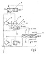
Fig. 6 zeigt eine Lösung gleichfalls wie inFig. 4 auf mit der Maßgabe, dass die Formgedächtnisfedern 48, 60 nunmehr mit ihren unterschiedlichen Temperaturbereichen parallel zueinander verschaltet sind. Bei der Lösung nach derFig. 7 wird wiederum eine Grundfunktion gemäß der Schaltung nach derFig. 4 erreicht, jedoch gibt es nunmehr zwei Vorsteuerventilsitze 42 und 58, die gemeinsam über eine Vorsteuer-Ventileinstelleinrichtung 44 jeweils ansteuerbar sind. - Alle Lösungen gemäß den
Figuren 4 bis 7 beinhalten die Erfassung der Tanktemperatur des Tanks T. - Insgesamt machen die angesprochenen exemplarischen Lösungen nach den
Figuren 1 bis 7 deutlich, dass das Verwenden von mehreren Thermoventilen an möglicherweise verschiedenen Orten im Hydraulikschaltplan zur Ansteuerung einer Hauptstufe einsetzbar sind. Dabei ergeben sich die folgenden Kombinationen: - a.) Thermoventil als direkte Vorsteuerstufe des Hauptventils
- b.) wie a.) und mit Platzierung eines zusätzlichen Thermoventils am Kühlerausgang
- c.) wie a.) und mit Platzierung eines zusätzlichen Thermoventils am Eingang des Kühlers
- d.) wie a.) und mit einer zusätzlichen Formgedächtnislegierungsfeder im Thermoventil
- e.) wie a.) und mit einer zusätzlichen Formgedächtnislegierungsfeder im weiteren Thermoventil
- f.) wie a.) und mit einem zusätzlich parallel geschalteten Thermoventil
- g.) wie a.) und mit einem zusätzlichen Thermoventil als Vorsteuerstufe
- h.) Kombinationen aus den vorstehend gezeigten Möglichkeiten mit Platzierung der Thermoventile an verschiedenen, in den Figuren nicht näher dargestellten Orten.
- Die jeweilige Feder, gebildet aus dem genannten Formgedächtnislegierungsmaterial, ändert bei Aktivierung, also bei Übersteigung einer gewissen vorgebbaren Temperatur ihre metallografische Gitterstruktur. Die Verspannung der Gitterstruktur ändert die Länge der Feder. Wird diese Längenänderung behindert, baut sich eine Kraft auf. Im kalten Zustand ist demgemäß die Formgedächtnislegierungsfeder entspannt, und der jeweilige Vorsteuerventilsitz ist geöffnet.
Claims (11)
- Hydraulische Lüftersteuerung, bestehend aus mindestens- einem Lüftermotor (10),- einer Druckversorgungseinrichtung, insbesondere Hydropumpe (12), zum Versorgen des Lüftermotors (10) mit einem Druckmedium, insbesondere in Form von Hydrauliköl und- einem die Regelung der Lüftermotordrehzahl steuernden Thermoventil (40, 54),
dadurch gekennzeichnet, dass das Thermoventil (40, 54) einen Energiespeicher, vorzugsweise in Form einer Druckfeder (48, 60), bestehend aus einer Formgedächtnislegierung, aufweist. - Hydraulische Lüftersteuerung, bestehend aus mindestens- einem Lüftermotor (10),- einer Druckversorgungseinrichtung, insbesondere Hydropumpe (12), zum Versorgen des Lüftermotors (10) mit einem Druckmedium, insbesondere in Form von Hydrauliköl,- vorzugsweise einem Kühler-Thermo-Bypassventil (14), das den Rücklauf des Druckmediums aus einer an die Lüftereinrichtung anschließbaren Arbeitshydraulik steuert,- einem Bypass-Druckbegrenzungsventil (32), das den möglichen Fluidfluss zwischen der Druckversorgungseinrichtung (P) und einem Tankanschluss (T) steuert, und- einem Vorsteuer-Druckbegrenzungsventil (40, 54) für die Vorsteuerung des Bypass-Druckbegrenzungsventils (32).
- Hydraulische Lüftersteuerung nach Anspruch 2, dadurch gekennzeichnet, dass mindestens eines der Vorsteuer-Druckbegrenzungsventile (40, 54) einen Energiespeicher, vorzugsweise in Form der Druckfeder (48, 60), bestehend aus einer thermischen Formgedächtnislegierung, aufweist.
- Hydraulische Lüftersteuerung nach Anspruch 3, dadurch gekennzeichnet, dass die Formgedächtnislegierung eine temperaturabhängige Kraft-Hub-Kennlinie besitzt.
- Hydraulische Lüftersteuerung nach einem der Ansprüche 2 bis 4, dadurch gekennzeichnet, dass mindestens eines der Vorsteuer-Druckbegrenzungsventile (40, 54) medien- und/oder druckführend mit dem Federraum des Bypass-Druckbegrenzungsventils (32) verbunden ist.
- Hydraulische Lüftersteuerung nach einem der vorstehenden Ansprüche, dadurch gekennzeichnet, dass verschiedene Vorsteuer-Druckbegrenzungsventile (40, 54) vorhanden sind, die jeweils einen anderen Temperaturbereich für das eingesetzte Druckmedium abdecken.
- Hydraulische Lüftersteuerung nach einem der vorstehenden Ansprüche, dadurch gekennzeichnet, dass die einzelnen Vorsteuer-Druckbegrenzungsventile (40, 54) hintereinander in Reihe oder parallel zueinander geschaltet sind oder jedem Temperaturbereich zugeordnet mehrere Energiespeicher (48, 60) aufweisen, die parallel zueinander angeordnet mit unterschiedlichem Ansprechverhalten der jeweiligen Formgedächtnislegierung in einem Gehäuse eines Vorsteuer-Druckbegrenzungsventils (40) aufgenommen sind.
- Hydraulische Lüftersteuerung nach einem der vorstehenden Ansprüche, dadurch gekennzeichnet, dass zumindest bei einem Teil der Vorsteuer-Druckbegrenzungsventile (40, 54) diese mit ihrem Vorsteuerraum an den Tankanschluss (T) angeschlossen sind.
- Hydraulische Lüftersteuerung nach einem der vorstehenden Ansprüche, dadurch gekennzeichnet, dass mindestens ein Vorsteuer-Druckbegrenzungsventil (54) hinter einem Kühler (26) oder in Parallelschaltung zu diesem in den Versorgungskreis geschaltet ist, der aus dem Rücklauf der Arbeitshydraulik bedient wird.
- Hydraulische Lüftersteuerung nach einem der vorstehenden Ansprüche, dadurch gekennzeichnet, dass zwischen der Druckversorgungseinrichtung (P) und dem Bypass-Druckbegrenzungsventil (32) eine Druckbegrenzungseinrichtung (28) in Nebenstromanordnung geschaltet ist.
- Hydraulische Lüftersteuerung nach einem der vorstehenden Ansprüche, dadurch gekennzeichnet, dass zumindest in einer Schaltstellung das Kühler-Thermo-Bypassventil (14) das Druckmedium aus dem Rücklauf in den Tank (T) fördert, in einer weiteren Schaltstellung bei warmem Druckmedium eine Aufteilung zwischen Tank (T) und zu dem Kühler (26) aufteilt und bei heißem Druckmedium dieses vorrangig an den Kühler (26) weiterliefert.
Applications Claiming Priority (1)
| Application Number | Priority Date | Filing Date | Title |
|---|---|---|---|
| DE102013014286.5A DE102013014286A1 (de) | 2013-08-21 | 2013-08-21 | Hydraulische Lüftersteuerung |
Publications (2)
| Publication Number | Publication Date |
|---|---|
| EP2840284A1 true EP2840284A1 (de) | 2015-02-25 |
| EP2840284B1 EP2840284B1 (de) | 2017-12-06 |
Family
ID=51292784
Family Applications (1)
| Application Number | Title | Priority Date | Filing Date |
|---|---|---|---|
| EP14002734.3A Active EP2840284B1 (de) | 2013-08-21 | 2014-08-05 | Hydraulische Lüftersteuerung |
Country Status (2)
| Country | Link |
|---|---|
| EP (1) | EP2840284B1 (de) |
| DE (1) | DE102013014286A1 (de) |
Cited By (3)
| Publication number | Priority date | Publication date | Assignee | Title |
|---|---|---|---|---|
| EP3267038A1 (de) * | 2016-07-05 | 2018-01-10 | Fluid-O-Tech S.r.l. | Hydraulikpumpe und entsprechendes multifunktionsventil |
| WO2024001185A1 (zh) * | 2022-06-29 | 2024-01-04 | 三一重机有限公司 | 风扇控制方法、装置及作业机械 |
| CN117912378A (zh) * | 2024-03-20 | 2024-04-19 | 云南索特科技有限公司 | 一种拼接缝隙小且具有智能温控功能的led显示屏 |
Families Citing this family (2)
| Publication number | Priority date | Publication date | Assignee | Title |
|---|---|---|---|---|
| JP7182441B2 (ja) * | 2018-12-05 | 2022-12-02 | 日本電産トーソク株式会社 | 油圧制御装置 |
| DE102024002582A1 (de) * | 2024-08-08 | 2026-02-12 | Hydac Filtertechnik Gmbh | System zur Fluidversorgung |
Citations (4)
| Publication number | Priority date | Publication date | Assignee | Title |
|---|---|---|---|---|
| US3401605A (en) * | 1966-09-13 | 1968-09-17 | Abex Corp | Temperature responsive hydraulic system and valve means therefor |
| US3664129A (en) * | 1968-05-08 | 1972-05-23 | Hyster Co | Hydraulic cooling system |
| EP0097230A2 (de) * | 1982-06-18 | 1984-01-04 | Süddeutsche Kühlerfabrik Julius Fr. Behr GmbH & Co. KG | Lüfterantrieb für eine Kühlanlage, insbesondere für Schienenfahrzeuge |
| DE102010007247A1 (de) * | 2010-02-09 | 2011-08-11 | Hydac Filtertechnik GmbH, 66280 | Hydraulischer Lüfterantrieb |
Family Cites Families (4)
| Publication number | Priority date | Publication date | Assignee | Title |
|---|---|---|---|---|
| DE4308297A1 (de) * | 1992-03-20 | 1993-09-23 | Rexroth Mannesmann Gmbh | |
| DE19963499A1 (de) * | 1999-08-13 | 2001-02-15 | Mannesmann Rexroth Ag | Ventilanordnung |
| DE102006039554A1 (de) * | 2006-08-23 | 2008-03-06 | Zf Friedrichshafen Ag | Bypassventil für einen einem Hydraulikaggregat nachgeordneten Kühler |
| DE102010047793A1 (de) * | 2010-10-07 | 2011-06-30 | Daimler AG, 70327 | Kraftfahrzeugkühlvorrichtung |
-
2013
- 2013-08-21 DE DE102013014286.5A patent/DE102013014286A1/de not_active Withdrawn
-
2014
- 2014-08-05 EP EP14002734.3A patent/EP2840284B1/de active Active
Patent Citations (4)
| Publication number | Priority date | Publication date | Assignee | Title |
|---|---|---|---|---|
| US3401605A (en) * | 1966-09-13 | 1968-09-17 | Abex Corp | Temperature responsive hydraulic system and valve means therefor |
| US3664129A (en) * | 1968-05-08 | 1972-05-23 | Hyster Co | Hydraulic cooling system |
| EP0097230A2 (de) * | 1982-06-18 | 1984-01-04 | Süddeutsche Kühlerfabrik Julius Fr. Behr GmbH & Co. KG | Lüfterantrieb für eine Kühlanlage, insbesondere für Schienenfahrzeuge |
| DE102010007247A1 (de) * | 2010-02-09 | 2011-08-11 | Hydac Filtertechnik GmbH, 66280 | Hydraulischer Lüfterantrieb |
Cited By (5)
| Publication number | Priority date | Publication date | Assignee | Title |
|---|---|---|---|---|
| EP3267038A1 (de) * | 2016-07-05 | 2018-01-10 | Fluid-O-Tech S.r.l. | Hydraulikpumpe und entsprechendes multifunktionsventil |
| US11236744B2 (en) | 2016-07-05 | 2022-02-01 | Fluid-O-Tech, S.r.l. | Hydraulic pump and respective multifunction valve |
| WO2024001185A1 (zh) * | 2022-06-29 | 2024-01-04 | 三一重机有限公司 | 风扇控制方法、装置及作业机械 |
| CN117912378A (zh) * | 2024-03-20 | 2024-04-19 | 云南索特科技有限公司 | 一种拼接缝隙小且具有智能温控功能的led显示屏 |
| CN117912378B (zh) * | 2024-03-20 | 2024-05-31 | 云南索特科技有限公司 | 一种拼接缝隙小且具有智能温控功能的led显示屏 |
Also Published As
| Publication number | Publication date |
|---|---|
| DE102013014286A1 (de) | 2015-02-26 |
| EP2840284B1 (de) | 2017-12-06 |
Similar Documents
| Publication | Publication Date | Title |
|---|---|---|
| EP2705278B1 (de) | Kupplungsgetriebe | |
| EP2840284B1 (de) | Hydraulische Lüftersteuerung | |
| DE102015201001A1 (de) | Thermostatisches Bypassventil | |
| DE102017200874A1 (de) | Elektrische Kühlmittelpumpe | |
| DE102016209592B4 (de) | Ventil für ein Fahrzeug | |
| WO2017029227A1 (de) | Druck- und temperaturgesteuertes ventil in einem ölkreislauf einer brennkraftmaschine | |
| DE102004020589A1 (de) | Temperaturabhängige Strömungsregelventile für Motorkühlsysteme | |
| DE102015219601A1 (de) | Ölkühler für ein fahrzeug mit einem bypassventil, das durch eine temperatur eines arbeitsfluids betätigt wird | |
| DE102010007247A1 (de) | Hydraulischer Lüfterantrieb | |
| DE102016205488A1 (de) | Kühlvorrichtung zur Wärmeabfuhr | |
| WO2014106535A1 (de) | Ventil zur temperaturabhängigen ansteuerung mindestens eines hydraulischen verbrauchers | |
| DE202016008471U1 (de) | Thermostat-Aufbau mit variablem Ventilsitz | |
| DE102015211929A1 (de) | Ablassvorrichtung für Öl-Kreislauf von Motor | |
| DE102022132372A1 (de) | Heizungsanlage | |
| DE102010047793A1 (de) | Kraftfahrzeugkühlvorrichtung | |
| DE102007063489B4 (de) | Verfahren zum Steuern einer Heizanlage mit einer einen von einem Brenner beheizten Wärmetauscher aufweisenden, insbesondere im Brennwertbereich betriebenen Wärmequelle | |
| DE102004058864B4 (de) | Verfahren und Vorrichtung zur kraftstoffverbrauchsorientierten Kühlung von Verbrennungskraftmaschinen mittels eines schaltbaren Zusatzventils | |
| DE102016124675A1 (de) | Thermostatventil für eine Verbrennungskraftmaschine | |
| EP3133296B1 (de) | Ventilvorrichtung zum steuern eines fluidstroms sowie stromregelventil | |
| DE102015121572B4 (de) | Hydraulikanordnung und Kraftfahrzeugantriebsstrang | |
| AT521086A1 (de) | Konditioniereinrichtung zur Regelung eines gasförmigen oder | |
| DE1908922B2 (de) | Hydraulische Vorrichtung zur stufenlosen Regelung der Drehzahl von Lüftermotoren und zur Verstellung von Hauptkühlerund Nebenkühler Jalousien bei Brennkraftmaschinen, insbesondere in Schienenfahrzeugen | |
| EP3121523B1 (de) | Heizungssystem und verfahren zum betrieb eines heizungssystems | |
| WO2020177963A1 (de) | Kühlmittelkreislauf in einem fahrzeug | |
| DE19601376A1 (de) | Meßfühlerschaltung |
Legal Events
| Date | Code | Title | Description |
|---|---|---|---|
| PUAI | Public reference made under article 153(3) epc to a published international application that has entered the european phase |
Free format text: ORIGINAL CODE: 0009012 |
|
| 17P | Request for examination filed |
Effective date: 20141105 |
|
| AK | Designated contracting states |
Kind code of ref document: A1 Designated state(s): AL AT BE BG CH CY CZ DE DK EE ES FI FR GB GR HR HU IE IS IT LI LT LU LV MC MK MT NL NO PL PT RO RS SE SI SK SM TR |
|
| AX | Request for extension of the european patent |
Extension state: BA ME |
|
| GRAP | Despatch of communication of intention to grant a patent |
Free format text: ORIGINAL CODE: EPIDOSNIGR1 |
|
| INTG | Intention to grant announced |
Effective date: 20170828 |
|
| GRAS | Grant fee paid |
Free format text: ORIGINAL CODE: EPIDOSNIGR3 |
|
| GRAA | (expected) grant |
Free format text: ORIGINAL CODE: 0009210 |
|
| AK | Designated contracting states |
Kind code of ref document: B1 Designated state(s): AL AT BE BG CH CY CZ DE DK EE ES FI FR GB GR HR HU IE IS IT LI LT LU LV MC MK MT NL NO PL PT RO RS SE SI SK SM TR |
|
| REG | Reference to a national code |
Ref country code: GB Ref legal event code: FG4D Free format text: NOT ENGLISH |
|
| REG | Reference to a national code |
Ref country code: AT Ref legal event code: REF Ref document number: 952673 Country of ref document: AT Kind code of ref document: T Effective date: 20171215 Ref country code: CH Ref legal event code: EP |
|
| REG | Reference to a national code |
Ref country code: IE Ref legal event code: FG4D Free format text: LANGUAGE OF EP DOCUMENT: GERMAN |
|
| REG | Reference to a national code |
Ref country code: DE Ref legal event code: R096 Ref document number: 502014006447 Country of ref document: DE |
|
| REG | Reference to a national code |
Ref country code: NL Ref legal event code: MP Effective date: 20171206 |
|
| REG | Reference to a national code |
Ref country code: LT Ref legal event code: MG4D |
|
| PG25 | Lapsed in a contracting state [announced via postgrant information from national office to epo] |
Ref country code: LT Free format text: LAPSE BECAUSE OF FAILURE TO SUBMIT A TRANSLATION OF THE DESCRIPTION OR TO PAY THE FEE WITHIN THE PRESCRIBED TIME-LIMIT Effective date: 20171206 Ref country code: ES Free format text: LAPSE BECAUSE OF FAILURE TO SUBMIT A TRANSLATION OF THE DESCRIPTION OR TO PAY THE FEE WITHIN THE PRESCRIBED TIME-LIMIT Effective date: 20171206 Ref country code: NO Free format text: LAPSE BECAUSE OF FAILURE TO SUBMIT A TRANSLATION OF THE DESCRIPTION OR TO PAY THE FEE WITHIN THE PRESCRIBED TIME-LIMIT Effective date: 20180306 Ref country code: SE Free format text: LAPSE BECAUSE OF FAILURE TO SUBMIT A TRANSLATION OF THE DESCRIPTION OR TO PAY THE FEE WITHIN THE PRESCRIBED TIME-LIMIT Effective date: 20171206 Ref country code: FI Free format text: LAPSE BECAUSE OF FAILURE TO SUBMIT A TRANSLATION OF THE DESCRIPTION OR TO PAY THE FEE WITHIN THE PRESCRIBED TIME-LIMIT Effective date: 20171206 |
|
| PG25 | Lapsed in a contracting state [announced via postgrant information from national office to epo] |
Ref country code: RS Free format text: LAPSE BECAUSE OF FAILURE TO SUBMIT A TRANSLATION OF THE DESCRIPTION OR TO PAY THE FEE WITHIN THE PRESCRIBED TIME-LIMIT Effective date: 20171206 Ref country code: HR Free format text: LAPSE BECAUSE OF FAILURE TO SUBMIT A TRANSLATION OF THE DESCRIPTION OR TO PAY THE FEE WITHIN THE PRESCRIBED TIME-LIMIT Effective date: 20171206 Ref country code: GR Free format text: LAPSE BECAUSE OF FAILURE TO SUBMIT A TRANSLATION OF THE DESCRIPTION OR TO PAY THE FEE WITHIN THE PRESCRIBED TIME-LIMIT Effective date: 20180307 Ref country code: LV Free format text: LAPSE BECAUSE OF FAILURE TO SUBMIT A TRANSLATION OF THE DESCRIPTION OR TO PAY THE FEE WITHIN THE PRESCRIBED TIME-LIMIT Effective date: 20171206 Ref country code: BG Free format text: LAPSE BECAUSE OF FAILURE TO SUBMIT A TRANSLATION OF THE DESCRIPTION OR TO PAY THE FEE WITHIN THE PRESCRIBED TIME-LIMIT Effective date: 20180306 |
|
| PG25 | Lapsed in a contracting state [announced via postgrant information from national office to epo] |
Ref country code: NL Free format text: LAPSE BECAUSE OF FAILURE TO SUBMIT A TRANSLATION OF THE DESCRIPTION OR TO PAY THE FEE WITHIN THE PRESCRIBED TIME-LIMIT Effective date: 20171206 |
|
| REG | Reference to a national code |
Ref country code: FR Ref legal event code: PLFP Year of fee payment: 5 |
|
| PG25 | Lapsed in a contracting state [announced via postgrant information from national office to epo] |
Ref country code: CZ Free format text: LAPSE BECAUSE OF FAILURE TO SUBMIT A TRANSLATION OF THE DESCRIPTION OR TO PAY THE FEE WITHIN THE PRESCRIBED TIME-LIMIT Effective date: 20171206 Ref country code: SK Free format text: LAPSE BECAUSE OF FAILURE TO SUBMIT A TRANSLATION OF THE DESCRIPTION OR TO PAY THE FEE WITHIN THE PRESCRIBED TIME-LIMIT Effective date: 20171206 Ref country code: EE Free format text: LAPSE BECAUSE OF FAILURE TO SUBMIT A TRANSLATION OF THE DESCRIPTION OR TO PAY THE FEE WITHIN THE PRESCRIBED TIME-LIMIT Effective date: 20171206 |
|
| PG25 | Lapsed in a contracting state [announced via postgrant information from national office to epo] |
Ref country code: PL Free format text: LAPSE BECAUSE OF FAILURE TO SUBMIT A TRANSLATION OF THE DESCRIPTION OR TO PAY THE FEE WITHIN THE PRESCRIBED TIME-LIMIT Effective date: 20171206 Ref country code: RO Free format text: LAPSE BECAUSE OF FAILURE TO SUBMIT A TRANSLATION OF THE DESCRIPTION OR TO PAY THE FEE WITHIN THE PRESCRIBED TIME-LIMIT Effective date: 20171206 Ref country code: SM Free format text: LAPSE BECAUSE OF FAILURE TO SUBMIT A TRANSLATION OF THE DESCRIPTION OR TO PAY THE FEE WITHIN THE PRESCRIBED TIME-LIMIT Effective date: 20171206 |
|
| REG | Reference to a national code |
Ref country code: DE Ref legal event code: R097 Ref document number: 502014006447 Country of ref document: DE |
|
| PG25 | Lapsed in a contracting state [announced via postgrant information from national office to epo] |
Ref country code: MT Free format text: LAPSE BECAUSE OF FAILURE TO SUBMIT A TRANSLATION OF THE DESCRIPTION OR TO PAY THE FEE WITHIN THE PRESCRIBED TIME-LIMIT Effective date: 20171206 |
|
| PLBE | No opposition filed within time limit |
Free format text: ORIGINAL CODE: 0009261 |
|
| STAA | Information on the status of an ep patent application or granted ep patent |
Free format text: STATUS: NO OPPOSITION FILED WITHIN TIME LIMIT |
|
| 26N | No opposition filed |
Effective date: 20180907 |
|
| PG25 | Lapsed in a contracting state [announced via postgrant information from national office to epo] |
Ref country code: SI Free format text: LAPSE BECAUSE OF FAILURE TO SUBMIT A TRANSLATION OF THE DESCRIPTION OR TO PAY THE FEE WITHIN THE PRESCRIBED TIME-LIMIT Effective date: 20171206 Ref country code: DK Free format text: LAPSE BECAUSE OF FAILURE TO SUBMIT A TRANSLATION OF THE DESCRIPTION OR TO PAY THE FEE WITHIN THE PRESCRIBED TIME-LIMIT Effective date: 20171206 |
|
| PG25 | Lapsed in a contracting state [announced via postgrant information from national office to epo] |
Ref country code: MC Free format text: LAPSE BECAUSE OF FAILURE TO SUBMIT A TRANSLATION OF THE DESCRIPTION OR TO PAY THE FEE WITHIN THE PRESCRIBED TIME-LIMIT Effective date: 20171206 |
|
| REG | Reference to a national code |
Ref country code: CH Ref legal event code: PL |
|
| PG25 | Lapsed in a contracting state [announced via postgrant information from national office to epo] |
Ref country code: LI Free format text: LAPSE BECAUSE OF NON-PAYMENT OF DUE FEES Effective date: 20180831 Ref country code: LU Free format text: LAPSE BECAUSE OF NON-PAYMENT OF DUE FEES Effective date: 20180805 Ref country code: CH Free format text: LAPSE BECAUSE OF NON-PAYMENT OF DUE FEES Effective date: 20180831 |
|
| REG | Reference to a national code |
Ref country code: BE Ref legal event code: MM Effective date: 20180831 |
|
| REG | Reference to a national code |
Ref country code: IE Ref legal event code: MM4A |
|
| PG25 | Lapsed in a contracting state [announced via postgrant information from national office to epo] |
Ref country code: IE Free format text: LAPSE BECAUSE OF NON-PAYMENT OF DUE FEES Effective date: 20180805 |
|
| PG25 | Lapsed in a contracting state [announced via postgrant information from national office to epo] |
Ref country code: BE Free format text: LAPSE BECAUSE OF NON-PAYMENT OF DUE FEES Effective date: 20180831 |
|
| PG25 | Lapsed in a contracting state [announced via postgrant information from national office to epo] |
Ref country code: TR Free format text: LAPSE BECAUSE OF FAILURE TO SUBMIT A TRANSLATION OF THE DESCRIPTION OR TO PAY THE FEE WITHIN THE PRESCRIBED TIME-LIMIT Effective date: 20171206 |
|
| PG25 | Lapsed in a contracting state [announced via postgrant information from national office to epo] |
Ref country code: PT Free format text: LAPSE BECAUSE OF FAILURE TO SUBMIT A TRANSLATION OF THE DESCRIPTION OR TO PAY THE FEE WITHIN THE PRESCRIBED TIME-LIMIT Effective date: 20171206 Ref country code: HU Free format text: LAPSE BECAUSE OF FAILURE TO SUBMIT A TRANSLATION OF THE DESCRIPTION OR TO PAY THE FEE WITHIN THE PRESCRIBED TIME-LIMIT; INVALID AB INITIO Effective date: 20140805 |
|
| PG25 | Lapsed in a contracting state [announced via postgrant information from national office to epo] |
Ref country code: MK Free format text: LAPSE BECAUSE OF NON-PAYMENT OF DUE FEES Effective date: 20171206 Ref country code: CY Free format text: LAPSE BECAUSE OF FAILURE TO SUBMIT A TRANSLATION OF THE DESCRIPTION OR TO PAY THE FEE WITHIN THE PRESCRIBED TIME-LIMIT Effective date: 20171206 |
|
| PG25 | Lapsed in a contracting state [announced via postgrant information from national office to epo] |
Ref country code: AL Free format text: LAPSE BECAUSE OF FAILURE TO SUBMIT A TRANSLATION OF THE DESCRIPTION OR TO PAY THE FEE WITHIN THE PRESCRIBED TIME-LIMIT Effective date: 20171206 Ref country code: IS Free format text: LAPSE BECAUSE OF FAILURE TO SUBMIT A TRANSLATION OF THE DESCRIPTION OR TO PAY THE FEE WITHIN THE PRESCRIBED TIME-LIMIT Effective date: 20180406 |
|
| REG | Reference to a national code |
Ref country code: AT Ref legal event code: MM01 Ref document number: 952673 Country of ref document: AT Kind code of ref document: T Effective date: 20190805 |
|
| PG25 | Lapsed in a contracting state [announced via postgrant information from national office to epo] |
Ref country code: AT Free format text: LAPSE BECAUSE OF NON-PAYMENT OF DUE FEES Effective date: 20190805 |
|
| PGFP | Annual fee paid to national office [announced via postgrant information from national office to epo] |
Ref country code: GB Payment date: 20250611 Year of fee payment: 12 |
|
| PGFP | Annual fee paid to national office [announced via postgrant information from national office to epo] |
Ref country code: DE Payment date: 20250831 Year of fee payment: 12 |
|
| PGFP | Annual fee paid to national office [announced via postgrant information from national office to epo] |
Ref country code: IT Payment date: 20250710 Year of fee payment: 12 |
|
| PGFP | Annual fee paid to national office [announced via postgrant information from national office to epo] |
Ref country code: FR Payment date: 20250722 Year of fee payment: 12 |