EP2840251B1 - Injektorbohrungsring - Google Patents
Injektorbohrungsring Download PDFInfo
- Publication number
- EP2840251B1 EP2840251B1 EP14002306.0A EP14002306A EP2840251B1 EP 2840251 B1 EP2840251 B1 EP 2840251B1 EP 14002306 A EP14002306 A EP 14002306A EP 2840251 B1 EP2840251 B1 EP 2840251B1
- Authority
- EP
- European Patent Office
- Prior art keywords
- cylinder head
- support ring
- tmf
- injector
- head according
- Prior art date
- Legal status (The legal status is an assumption and is not a legal conclusion. Google has not performed a legal analysis and makes no representation as to the accuracy of the status listed.)
- Active
Links
Images




Classifications
-
- F—MECHANICAL ENGINEERING; LIGHTING; HEATING; WEAPONS; BLASTING
- F02—COMBUSTION ENGINES; HOT-GAS OR COMBUSTION-PRODUCT ENGINE PLANTS
- F02M—SUPPLYING COMBUSTION ENGINES IN GENERAL WITH COMBUSTIBLE MIXTURES OR CONSTITUENTS THEREOF
- F02M61/00—Fuel-injectors not provided for in groups F02M39/00 - F02M57/00 or F02M67/00
- F02M61/14—Arrangements of injectors with respect to engines; Mounting of injectors
-
- F—MECHANICAL ENGINEERING; LIGHTING; HEATING; WEAPONS; BLASTING
- F02—COMBUSTION ENGINES; HOT-GAS OR COMBUSTION-PRODUCT ENGINE PLANTS
- F02M—SUPPLYING COMBUSTION ENGINES IN GENERAL WITH COMBUSTIBLE MIXTURES OR CONSTITUENTS THEREOF
- F02M2200/00—Details of fuel-injection apparatus, not otherwise provided for
- F02M2200/85—Mounting of fuel injection apparatus
- F02M2200/858—Mounting of fuel injection apparatus sealing arrangements between injector and engine
-
- F—MECHANICAL ENGINEERING; LIGHTING; HEATING; WEAPONS; BLASTING
- F02—COMBUSTION ENGINES; HOT-GAS OR COMBUSTION-PRODUCT ENGINE PLANTS
- F02M—SUPPLYING COMBUSTION ENGINES IN GENERAL WITH COMBUSTIBLE MIXTURES OR CONSTITUENTS THEREOF
- F02M2200/00—Details of fuel-injection apparatus, not otherwise provided for
- F02M2200/90—Selection of particular materials
- F02M2200/9053—Metals
Definitions
- the invention relates to an injector bore ring.
- the object of the present invention is to provide a solution with which the stresses in the injector bore or in the valve webs can be influenced in a targeted manner in order to minimize the risk of TMF cracks.
- the object of the present invention is achieved by countersinking and inserting an injector bore ring (TMF support ring) in the region of the injector bore of the cylinder head, as defined in claim 1.
- TMF support ring injector bore ring
- the geometry of the ring and the selection of the material (modulus of elasticity, strength) and the press-in oversize have a decisive influence on the success of this measure and are to be defined individually as design parameters, so that the local stresses in the cylinder head of an internal combustion engine are reduced and the thermomechanical damage minimized.
- a bore in the base plate of the cylinder head is provided on the cylinder head of an internal combustion engine with direct fuel injection for positioning and for introducing the injector into the combustion chamber.
- TMF support ring which surrounds the injector bore provided in the cylinder head base plate and which allows the local rigidity to be influenced in a targeted manner.
- a depression is made on the injector bore, into which this ring is inserted and held by means of frictional engagement (press fit).
- An alternative embodiment provides for the ring to be used directly during casting and to be connected to the cylinder head via a positive fit.
- the geometry of the ring, the selection of the material (modulus of elasticity, strength) and, if applicable, the choice of the press-in oversize have a decisive influence on the success of this measure and are to be defined individually as design parameters.
- these parameters are selected so that the locally high load is borne by the injector bore ring (support ring) and the Cylinder head structure is relieved compared to the situation without a support ring. This increases the service life in the area of the injector bore.
- the material and press fit of the ring must be selected so that on the one hand an adequate support effect is achieved, but on the other hand no excessive tensile stresses occur in the ring seat of the cylinder head, which in turn has a counterproductive effect on the operational strength.
- the injector bore ring can also be used in a possible embodiment variant as a "soft" ring to adjust the rigidity of the base plate and to reduce this in a targeted manner. In this case, the thermal expansion hindrance and the mechanical stress on the valve webs are reduced. This increases the service life in the area of the valve lands.
- FIG 1 shows a typical application in a cylinder head which is designed with an injector sleeve.
- the section line AA runs in Figure 2 is shown
- Figure 2 a detail B that is in the Figure 3 is disclosed.
- FIG 3 the cylinder head with the injector sleeve 3 is shown.
- a so-called TMF support ring 2 is arranged concentrically around the injector sleeve 3 in such a way that it is essentially flush with the end of the injector sleeve 3 protruding into the combustion chamber and the cylinder head base plate.
- Figure 4 shows an example of a base plate of a cylinder head and the typical areas exposed to TMF.
- the injector bore 1 and the valve webs 2 can be seen.
- Suitable materials for the injector bore ring include steel, aluminum alloys or copper or copper alloys.
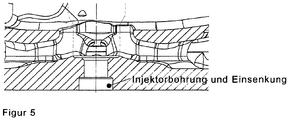
- Figure 5 shows a bottom plate of the cylinder head in a sectional view with the injector bore and a depression arranged on the combustion chamber end of the injector bore for receiving the injector bore ring.
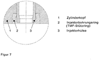
- FIG. 7 issues detail A.
- Figure 6 In detail A from Figure 6 the cylinder head 1 with the injector sleeve 3 is shown.
- a so-called TMF support ring 2 which is also referred to as injector bore ring 2, is arranged concentrically around the injector sleeve 3 in such a way that it is essentially flush with the end of the injector sleeve 3 which projects into the combustion chamber and the cylinder head base plate.
- Figure 8 are typical dimensions of the injector bore ring 2 Figure 7 shown.
Landscapes
- Engineering & Computer Science (AREA)
- Chemical & Material Sciences (AREA)
- Combustion & Propulsion (AREA)
- Mechanical Engineering (AREA)
- General Engineering & Computer Science (AREA)
- Cylinder Crankcases Of Internal Combustion Engines (AREA)
Description
- Die Erfindung betrifft einen Injektorbohrungsring.
- Aus dem Stand der Technik ist bekannt, dass die Führung des Injektors mit Hilfe eines im Zylinderkopf integrierten Injektordoms (wie in der
WO2006/072333A1 veröffentlicht) oder mit Hilfe einer separaten Hülse (z.B. aus Kupfer oder Stahl, wie in derDE 10 2010 033 710 A1 veröffentlicht) erfolgt. Im ersten Fall sind die Maße der erforderlichen Bohrung in der Bodenplatte durch den Außendurchmesser des Injektor-Düsenelementes gegeben; im zweiten Fall sind die Maße der Bohrung durch den Außendurchmesser der verwendeten Hülse gegeben. Nachteilig daran ist, dass in beiden Fällen der Bohrungsdurchmesser und damit ein wichtiger Einflussparameter der lokalen Steifigkeit der Bodenplatte nicht oder nur sehr geringfügig variiert werden kann. - Weiterhin ist bekannt, dass im Einsatz der Verbrennungskraftmaschine an der Bodenplatte des Zylinderkopfes hohe wechselnde Beanspruchungen durch das Aufheizen und Abkühlen des Aggregats auftreten. Die lokalen Beanspruchungen sind von der Temperaturlast des Zylinderkopfes und der Steifigkeitsverteilung innerhalb der Bodenplatte abhängig und können zu Anrissen infolge einer thermomechanischen Ermüdung (Thermo Mechanical Fatigue TMF) führen. Besonders gefährdet hinsichtlich derartiger Anrisse sind die Stegbereiche zwischen zwei Ventilen und der Bereich der Injektorbohrung.
- Die Aufgabe der vorliegenden Erfindung ist es, eine Lösung bereitzustellen, mit der die Beanspruchungen in der Injektorbohrung bzw. in den Ventilstegen gezielt beeinflusst werden können, um das Risiko von TMF-Anrissen zu minimieren.
- Die Aufgabe der vorliegenden Erfindung wird durch eine Einsenkung und ein Einsetzen eines Injektorbohrungsrings (TMF-Stützring) im Bereich der Injektorbohrung des Zylinderkopfes, wie im Anspruch 1 definiert, gelöst. Die Geometrie des Ringes und die Auswahl des Werkstoffes (E-Modul, Festigkeit) und des Einpressübermaßes haben einen entscheidenden Einfluss auf den Erfolg dieser Maßnahme und sind als Auslegungsparameter jeweils individuell festzulegen, so dass sich die lokalen Beanspruchungen in dem Zylinderkopf einer Verbrennungskraftmaschine reduzieren und die thermomechanische Schädigung minimiert. An dem Zylinderkopf einer Verbrennungskraftmaschine mit direkter Kraftstoffeinspritzung wird zur Positionierung und zur Einführung des Injektors in den Brennraum eine Bohrung in der Bodenplatte des Zylinderkopfes vorgesehen.
- In einer weiteren vorteilhaften Weiterbildung ist vorgesehen, einen Injektorbohrungsring (TMF-Stützring) zu verwenden, der die in der Zylinderkopfbodenplatte vorgesehene Injektorbohrung umschließt und der eine gezielte Beeinflussung der lokalen Steifigkeit erlaubt.
- An der Injektorbohrung wird hierzu eine Einsenkung gefertigt, in die dieser Ring eingesetzt und mittels Reibschluss gehalten wird (Presspassung). Eine alternative Ausgestaltung sieht vor, den Ring unmittelbar beim Gießen einzusetzen und über Formschluss mit dem Zylinderkopf zu verbinden.
- Die Geometrie des Ringes, die Auswahl des Werkstoffes (E-Modul, Festigkeit) und ggf. die Wahl des Einpressübermaßes haben einen entscheidenden Einfluss auf den Erfolg dieser Maßnahme und sind als Auslegungsparameter jeweils individuell festzulegen.
- Weitere vorteilhafte Ausgestaltungen sind in den Unteransprüchen enthalten.
- Um die mechanischen Beanspruchungen im Bereich der Injektorbohrung zu reduzieren, werden diese Parameter so gewählt, dass die örtlich hohe Belastung von dem Injektorbohrungsring (Stützring) getragen wird und die Zylinderkopfstruktur im Vergleich zu der Situation ohne Stützring entlastet wird. Die Lebensdauer im Bereich der Injektorbohrung wird dadurch erhöht. Werkstoff und Einpressübermaß des Ringes sind in diesem Fall so auszuwählen, dass einerseits eine ausreichende Stützwirkung erzielt wird, andererseits aber keine übermäßigen Zugspannungen in der Ringaufnahme des Zylinderkopfes entstehen, die sich wiederum kontraproduktiv auf die Betriebsfestigkeit auswirkt.
- Um die mechanischen Beanspruchungen in den Ventilstegen zu reduzieren, kann der Injektorbohrungsring in einer möglichen Ausführungsvariante als "weicher" Ring auch dazu verwendet werden, die Steifigkeit der Bodenplatte einzustellen und diese gezielt zu verringern. In diesem Fall wird die thermische Dehnungsbehinderung und die mechanische Beanspruchung der Ventilstege reduziert. Die Lebensdauer im Bereich der Ventilstege wird dadurch erhöht.
- Weitere Merkmale der Erfindung ergeben sich aus der folgenden Beschreibung und den Zeichnungen, auf denen ein Ausführungsbeispiel dargestellt ist.
- Es zeigen:
- Figur 1
- Zylinderkopf mit einer Injektorhülse
- Figur 2
- den Schnitt A-A aus
Figur 1 - Figur 3
- das Detail B aus
Figur 1 - Figur 4
- das Beispiel einer Bodenplatte eines Zylinderkopfs und der typischen TMF-gefährdeten Bereiche
- Figur 5
- die Bodenplatte des Zylinderkopfes in Schnittdarstellung
- Figur 6
- die Bodenplatte des Zylinderkopfs mit Injektorbohrungsring und Injektorhülse
- Figur 7
- das Detail A aus
Figur 6 - Figur 8
- die Proportionen des geschnittenen Injektorbohrungsring
-
Figur 1 zeigt eine typische Anwendung bei einem Zylinderkopf, der mit einer Injektorhülse ausgeführt ist. Durch die Injektorbohrung hindurch verläuft die Schnittlinie A-A, die inFigur 2 dargestellt wird.Weiter zeigtFigur 2 ein Detail B, das in derFigur 3 offenbart wird. In Detail B inFigur 3 wird der Zylinderkopf mit der Injektorhülse 3 gezeigt. Um die Injektorhülse 3 herum ist ein sogenannter TMF-Stützring 2 konzentrisch so angeordnet, dass er mit dem in den Brennraum ragenden Ende der Injektorhülse 3 und dem Zylinderkopfbodenplatte im Wesentlichen bündig abschliesst. -
Figur 4 zeigt ein Beispiel einer Bodenplatte eines Zylinderkopfes und der typischen TMF-gefährdeten Bereiche. Zu sehen sind die Injektorbohrung 1 und die Ventilstege 2. - Geeignete Werkstoffe für den Injektorbohrungsring sind unter anderem Stähle, Aluminiumlegierungen oder Kupfer bzw. Kupferlegierungen.
-
Figur 5 zeigt eine Bodenplatte des Zylinderkopfes in Schnittdarstellung mit der Injektorbohrung und einer am brennraumseitigen Ende der Injektorbohrung angeordneten Einsenkung zur Aufnahme des Injektorbohrungsrings. - In
Figur 6 wird eine Bodenplatte des Zylinderkopfes mit einem Injektorbohrungsring und einer Injektorhülse im Detail A dargestellt, das in der folgendenFigur 7 detailreicher offenbart wird. -
Figur 7 stellt das Detail A ausFigur 6 dar. In Detail A ausFigur 6 wird der Zylinderkopf 1 mit der Injektorhülse 3 gezeigt. Um die Injektorhülse 3 herum ist ein sogenannter TMF-Stützring 2, der auch als Injektorbohrungsring 2 bezeichnet wird konzentrisch so angeordnet, dass er mit dem in den Brennraum ragenden Ende der Injektorhülse 3 und dem Zylinderkopfbodenplatte im Wesentlichen bündig abschließt. - In
Figur 8 werden typische Abmessungen des Injektorbohrungsringes 2 ausFigur 7 dargestellt.
Claims (7)
- Zylinderkopf für eine Brennkraftmaschine, die ein Kurbelgehäuse und eine darin drehbar gelagerte Kurbelwelle aufweist, an der jeweils mit einem Kolben verbundene Pleuel angelenkt sind, wobei der Kolben in einem von dem Zylinderkopf abgedeckten Zylinder unter Bildung eines Brennraums bewegbar ist, umfassend wenigstens eine Nockenwellen, die je Zylinder wenigstens ein Gaswechselventil, insbesondere ein Einlassventile und ein Auslassventil steuert, wobei ein Injektor in eine zentrale Ausnehmung einsetzbar ist, die als von schmierölführenden und/oder kühlmittelführenden Räumen getrennter Bereich ausgebildet ist, wobei sich die Ausnehmung vom Brennraum aus durch den Zylinderkopf hindurch erstreckt, und wobei die Führung des Injektordoms mit Hilfe einer separaten Hülse (3) erfolgt, dadurch gekennzeichnet, dass in dem dem Brennraum zugewandten Bereich des Zylinderkopfs um die Injektorhülse (3) herum ein TMF-Stützring [Injektorbohrungsring; Thermo Mechanical Fatigue (TMF)] (2) konzentrisch so angeordnet ist, dass er mit dem in den Brennraum ragenden Ende der Injektorhülse (3) und der Zylinderkopf-Bodenplatte im Wesentlichen bündig abschließt.
- Zylinderkopf nach einem oder mehreren der vorgenannten Ansprüche, dadurch gekennzeichnet, dass der TMF-Stützring aus Kupfer ausgeführt ist.
- Zylinderkopf nach einem oder mehreren der vorgenannten Ansprüche, dadurch gekennzeichnet, dass der TMF-Stützring aus Aluminium angeordnet ist.
- Zylinderkopf nach einem oder mehreren der vorgenannten Ansprüche, dadurch gekennzeichnet, dass der TMF-Stützring aus Stahl angeordnet ist.
- Zylinderkopf nach einem oder mehreren der vorgenannten Ansprüche, dadurch gekennzeichnet, dass der TMF-Stützring aus einer Legierung angeordnet ist.
- Zylinderkopf nach einem oder mehreren der vorgenannten Ansprüche, dadurch gekennzeichnet, dass das Verhältnis von Außendurchmesser des Stützrings zu Innendurchmesser des Stützrings im Wesentlichen in einem Bereich von 1,25 bis 2,1 liegt, die Höhe des Stützrings beträgt in etwa das 0,4 bis 1,4-fache des Innendurchmessers des Stützrings.
- Zylinderkopf nach einem oder mehreren der vorgenannten Ansprüche, dadurch gekennzeichnet, dass der TMF-Stützring geschweißt, gelötet, geschrumpft, geklebt, oder gesintert ausgeführt wird.
Applications Claiming Priority (1)
| Application Number | Priority Date | Filing Date | Title |
|---|---|---|---|
| DE102013013090.5A DE102013013090A1 (de) | 2013-08-07 | 2013-08-07 | Injektorbohrungsring |
Publications (2)
| Publication Number | Publication Date |
|---|---|
| EP2840251A1 EP2840251A1 (de) | 2015-02-25 |
| EP2840251B1 true EP2840251B1 (de) | 2019-12-18 |
Family
ID=51205128
Family Applications (1)
| Application Number | Title | Priority Date | Filing Date |
|---|---|---|---|
| EP14002306.0A Active EP2840251B1 (de) | 2013-08-07 | 2014-07-05 | Injektorbohrungsring |
Country Status (2)
| Country | Link |
|---|---|
| EP (1) | EP2840251B1 (de) |
| DE (1) | DE102013013090A1 (de) |
Citations (2)
| Publication number | Priority date | Publication date | Assignee | Title |
|---|---|---|---|---|
| GB191515151A (en) * | 1915-10-26 | 1916-01-06 | Marc Birkigt | Improvements in or relating to Fluid-tight Joints. |
| WO2006084915A1 (de) * | 2005-02-14 | 2006-08-17 | Siemens Aktiengesellschaft | Einspritzventil zum einspritzen von kraftstoff und zylinderkopf |
Family Cites Families (8)
| Publication number | Priority date | Publication date | Assignee | Title |
|---|---|---|---|---|
| DE19548088C1 (de) * | 1995-12-21 | 1997-07-17 | Daimler Benz Ag | Zylinderkopf für eine Brennkraftmaschine |
| DE10027669A1 (de) * | 2000-06-03 | 2001-12-06 | Bosch Gmbh Robert | Befestigungsmittel für ein Brennstoffeinspritzventil |
| DE10259559A1 (de) * | 2002-12-19 | 2004-07-15 | Mtu Friedrichshafen Gmbh | Kraftstoffeinspritzventil |
| DE102007034611A1 (de) * | 2007-07-25 | 2009-01-29 | Robert Bosch Gmbh | Vorrichtung zur Befestigung von Kraftstoffinjektoren |
| AT505049B1 (de) * | 2008-06-05 | 2009-10-15 | Avl List Gmbh | Brennkraftmaschine mit einem zylinderkopf |
| US9382887B2 (en) * | 2009-09-23 | 2016-07-05 | Cummins Intellectual Property. Inc. | Engine component seal assembly and method of sealing a coolant passage from an engine component |
| DE102010033710A1 (de) * | 2010-08-06 | 2012-02-09 | Deutz Ag | Zylinderkopf |
| EP2636880A1 (de) * | 2012-03-06 | 2013-09-11 | Delphi Automotive Systems Luxembourg SA | Dichtung für Einspritzdüse |
-
2013
- 2013-08-07 DE DE102013013090.5A patent/DE102013013090A1/de not_active Ceased
-
2014
- 2014-07-05 EP EP14002306.0A patent/EP2840251B1/de active Active
Patent Citations (2)
| Publication number | Priority date | Publication date | Assignee | Title |
|---|---|---|---|---|
| GB191515151A (en) * | 1915-10-26 | 1916-01-06 | Marc Birkigt | Improvements in or relating to Fluid-tight Joints. |
| WO2006084915A1 (de) * | 2005-02-14 | 2006-08-17 | Siemens Aktiengesellschaft | Einspritzventil zum einspritzen von kraftstoff und zylinderkopf |
Also Published As
| Publication number | Publication date |
|---|---|
| DE102013013090A1 (de) | 2015-02-12 |
| EP2840251A1 (de) | 2015-02-25 |
Similar Documents
| Publication | Publication Date | Title |
|---|---|---|
| EP3317565B1 (de) | Zylinderlaufbuchse für eine brennkraftmaschine | |
| WO2014059975A1 (de) | Steuerventil für ein nockenwellenverstellersystem | |
| WO2006056315A1 (de) | Leichtbaukolben für thermisch hochbelastete kolben | |
| CH697316B1 (de) | Leitapparat für eine Radialturbine. | |
| EP2938874B1 (de) | Ventilanordnung | |
| EP0099873A2 (de) | Zylindrischer Drehschieber mit Abdichtung für Kolbenmotoren | |
| EP2638379B1 (de) | Einrichtung zur reibungsmessung | |
| DE102011004403A1 (de) | Hydraulischer Ventiltrieb einer Brennkraftmaschine | |
| EP0961025A1 (de) | Brennstoffeinspritzdüse | |
| DE102004057558A1 (de) | Kolben für einen Verbrennungsmotor | |
| DE2727006A1 (de) | Tellerventil mit innenkuehlung, insbesondere auslassventil fuer hubkolbenbrennkraftmaschinen | |
| WO1997028355A1 (de) | Stössel für einen ventiltrieb einer brennkraftmaschine | |
| DE102016208907A1 (de) | Bogenförmige Anlaufscheibe für ein Zylinderkurbelgehäuse einer Hubkolben-Brennkraftmaschine | |
| EP2840251A1 (de) | Injektorbohrungsring | |
| DE3627505C2 (de) | Sich selbsttätig hydraulisch einstellender Ventilstößel | |
| AT522801B1 (de) | Brennkraftmaschine | |
| EP1076770B1 (de) | Kraftstoffeinspritzventil für brennkraftmaschinen | |
| CH717633B1 (de) | Druckaufnehmer zum Erfassen eines Brennraumdrucks bei Brennkraftmaschinen. | |
| EP2312149B1 (de) | Hochdruck-Kraftstoffkolbenpumpe | |
| DE102021114978A1 (de) | Brennkraftmaschine mit Kolbenkühleinrichtung | |
| DE102005037383A1 (de) | Zylinderkopf für eine Brennkraftmaschine | |
| DE3236354A1 (de) | Von verbrennungswaerme unmittelbar beaufschlagtes, axial hin- und hergehend bewegtes bauteil einer hubkolbenbrennkraftmaschine mit hitzeschild | |
| DE10221731A1 (de) | Buchsenabdichtring für eine Zylinderlaufbuchse | |
| DE10357860A1 (de) | Brennkraftmaschine | |
| DE102007034845A1 (de) | Ventiltrieb einer Brennkraftmaschine mit mechanischer Ventilspieleinstellung |
Legal Events
| Date | Code | Title | Description |
|---|---|---|---|
| PUAI | Public reference made under article 153(3) epc to a published international application that has entered the european phase |
Free format text: ORIGINAL CODE: 0009012 |
|
| 17P | Request for examination filed |
Effective date: 20140705 |
|
| AK | Designated contracting states |
Kind code of ref document: A1 Designated state(s): AL AT BE BG CH CY CZ DE DK EE ES FI FR GB GR HR HU IE IS IT LI LT LU LV MC MK MT NL NO PL PT RO RS SE SI SK SM TR |
|
| AX | Request for extension of the european patent |
Extension state: BA ME |
|
| R17P | Request for examination filed (corrected) |
Effective date: 20150806 |
|
| RBV | Designated contracting states (corrected) |
Designated state(s): AL AT BE BG CH CY CZ DE DK EE ES FI FR GB GR HR HU IE IS IT LI LT LU LV MC MK MT NL NO PL PT RO RS SE SI SK SM TR |
|
| 17Q | First examination report despatched |
Effective date: 20160705 |
|
| STAA | Information on the status of an ep patent application or granted ep patent |
Free format text: STATUS: EXAMINATION IS IN PROGRESS |
|
| GRAP | Despatch of communication of intention to grant a patent |
Free format text: ORIGINAL CODE: EPIDOSNIGR1 |
|
| STAA | Information on the status of an ep patent application or granted ep patent |
Free format text: STATUS: GRANT OF PATENT IS INTENDED |
|
| INTG | Intention to grant announced |
Effective date: 20190717 |
|
| GRAS | Grant fee paid |
Free format text: ORIGINAL CODE: EPIDOSNIGR3 |
|
| GRAA | (expected) grant |
Free format text: ORIGINAL CODE: 0009210 |
|
| STAA | Information on the status of an ep patent application or granted ep patent |
Free format text: STATUS: THE PATENT HAS BEEN GRANTED |
|
| AK | Designated contracting states |
Kind code of ref document: B1 Designated state(s): AL AT BE BG CH CY CZ DE DK EE ES FI FR GB GR HR HU IE IS IT LI LT LU LV MC MK MT NL NO PL PT RO RS SE SI SK SM TR |
|
| REG | Reference to a national code |
Ref country code: CH Ref legal event code: EP |
|
| REG | Reference to a national code |
Ref country code: DE Ref legal event code: R096 Ref document number: 502014013259 Country of ref document: DE |
|
| REG | Reference to a national code |
Ref country code: IE Ref legal event code: FG4D Free format text: LANGUAGE OF EP DOCUMENT: GERMAN |
|
| REG | Reference to a national code |
Ref country code: AT Ref legal event code: REF Ref document number: 1214870 Country of ref document: AT Kind code of ref document: T Effective date: 20200115 |
|
| REG | Reference to a national code |
Ref country code: SE Ref legal event code: TRGR |
|
| REG | Reference to a national code |
Ref country code: NL Ref legal event code: FP |
|
| PG25 | Lapsed in a contracting state [announced via postgrant information from national office to epo] |
Ref country code: BG Free format text: LAPSE BECAUSE OF FAILURE TO SUBMIT A TRANSLATION OF THE DESCRIPTION OR TO PAY THE FEE WITHIN THE PRESCRIBED TIME-LIMIT Effective date: 20200318 Ref country code: FI Free format text: LAPSE BECAUSE OF FAILURE TO SUBMIT A TRANSLATION OF THE DESCRIPTION OR TO PAY THE FEE WITHIN THE PRESCRIBED TIME-LIMIT Effective date: 20191218 Ref country code: GR Free format text: LAPSE BECAUSE OF FAILURE TO SUBMIT A TRANSLATION OF THE DESCRIPTION OR TO PAY THE FEE WITHIN THE PRESCRIBED TIME-LIMIT Effective date: 20200319 Ref country code: NO Free format text: LAPSE BECAUSE OF FAILURE TO SUBMIT A TRANSLATION OF THE DESCRIPTION OR TO PAY THE FEE WITHIN THE PRESCRIBED TIME-LIMIT Effective date: 20200318 Ref country code: LT Free format text: LAPSE BECAUSE OF FAILURE TO SUBMIT A TRANSLATION OF THE DESCRIPTION OR TO PAY THE FEE WITHIN THE PRESCRIBED TIME-LIMIT Effective date: 20191218 Ref country code: LV Free format text: LAPSE BECAUSE OF FAILURE TO SUBMIT A TRANSLATION OF THE DESCRIPTION OR TO PAY THE FEE WITHIN THE PRESCRIBED TIME-LIMIT Effective date: 20191218 |
|
| REG | Reference to a national code |
Ref country code: LT Ref legal event code: MG4D |
|
| PG25 | Lapsed in a contracting state [announced via postgrant information from national office to epo] |
Ref country code: RS Free format text: LAPSE BECAUSE OF FAILURE TO SUBMIT A TRANSLATION OF THE DESCRIPTION OR TO PAY THE FEE WITHIN THE PRESCRIBED TIME-LIMIT Effective date: 20191218 Ref country code: HR Free format text: LAPSE BECAUSE OF FAILURE TO SUBMIT A TRANSLATION OF THE DESCRIPTION OR TO PAY THE FEE WITHIN THE PRESCRIBED TIME-LIMIT Effective date: 20191218 |
|
| PG25 | Lapsed in a contracting state [announced via postgrant information from national office to epo] |
Ref country code: AL Free format text: LAPSE BECAUSE OF FAILURE TO SUBMIT A TRANSLATION OF THE DESCRIPTION OR TO PAY THE FEE WITHIN THE PRESCRIBED TIME-LIMIT Effective date: 20191218 |
|
| PG25 | Lapsed in a contracting state [announced via postgrant information from national office to epo] |
Ref country code: EE Free format text: LAPSE BECAUSE OF FAILURE TO SUBMIT A TRANSLATION OF THE DESCRIPTION OR TO PAY THE FEE WITHIN THE PRESCRIBED TIME-LIMIT Effective date: 20191218 Ref country code: RO Free format text: LAPSE BECAUSE OF FAILURE TO SUBMIT A TRANSLATION OF THE DESCRIPTION OR TO PAY THE FEE WITHIN THE PRESCRIBED TIME-LIMIT Effective date: 20191218 Ref country code: CZ Free format text: LAPSE BECAUSE OF FAILURE TO SUBMIT A TRANSLATION OF THE DESCRIPTION OR TO PAY THE FEE WITHIN THE PRESCRIBED TIME-LIMIT Effective date: 20191218 Ref country code: PT Free format text: LAPSE BECAUSE OF FAILURE TO SUBMIT A TRANSLATION OF THE DESCRIPTION OR TO PAY THE FEE WITHIN THE PRESCRIBED TIME-LIMIT Effective date: 20200513 |
|
| PG25 | Lapsed in a contracting state [announced via postgrant information from national office to epo] |
Ref country code: SM Free format text: LAPSE BECAUSE OF FAILURE TO SUBMIT A TRANSLATION OF THE DESCRIPTION OR TO PAY THE FEE WITHIN THE PRESCRIBED TIME-LIMIT Effective date: 20191218 Ref country code: SK Free format text: LAPSE BECAUSE OF FAILURE TO SUBMIT A TRANSLATION OF THE DESCRIPTION OR TO PAY THE FEE WITHIN THE PRESCRIBED TIME-LIMIT Effective date: 20191218 Ref country code: IS Free format text: LAPSE BECAUSE OF FAILURE TO SUBMIT A TRANSLATION OF THE DESCRIPTION OR TO PAY THE FEE WITHIN THE PRESCRIBED TIME-LIMIT Effective date: 20200418 |
|
| REG | Reference to a national code |
Ref country code: DE Ref legal event code: R097 Ref document number: 502014013259 Country of ref document: DE |
|
| PLBE | No opposition filed within time limit |
Free format text: ORIGINAL CODE: 0009261 |
|
| STAA | Information on the status of an ep patent application or granted ep patent |
Free format text: STATUS: NO OPPOSITION FILED WITHIN TIME LIMIT |
|
| PG25 | Lapsed in a contracting state [announced via postgrant information from national office to epo] |
Ref country code: DK Free format text: LAPSE BECAUSE OF FAILURE TO SUBMIT A TRANSLATION OF THE DESCRIPTION OR TO PAY THE FEE WITHIN THE PRESCRIBED TIME-LIMIT Effective date: 20191218 Ref country code: ES Free format text: LAPSE BECAUSE OF FAILURE TO SUBMIT A TRANSLATION OF THE DESCRIPTION OR TO PAY THE FEE WITHIN THE PRESCRIBED TIME-LIMIT Effective date: 20191218 |
|
| 26N | No opposition filed |
Effective date: 20200921 |
|
| PG25 | Lapsed in a contracting state [announced via postgrant information from national office to epo] |
Ref country code: SI Free format text: LAPSE BECAUSE OF FAILURE TO SUBMIT A TRANSLATION OF THE DESCRIPTION OR TO PAY THE FEE WITHIN THE PRESCRIBED TIME-LIMIT Effective date: 20191218 |
|
| PG25 | Lapsed in a contracting state [announced via postgrant information from national office to epo] |
Ref country code: MC Free format text: LAPSE BECAUSE OF FAILURE TO SUBMIT A TRANSLATION OF THE DESCRIPTION OR TO PAY THE FEE WITHIN THE PRESCRIBED TIME-LIMIT Effective date: 20191218 Ref country code: PL Free format text: LAPSE BECAUSE OF FAILURE TO SUBMIT A TRANSLATION OF THE DESCRIPTION OR TO PAY THE FEE WITHIN THE PRESCRIBED TIME-LIMIT Effective date: 20191218 |
|
| REG | Reference to a national code |
Ref country code: CH Ref legal event code: PL |
|
| REG | Reference to a national code |
Ref country code: BE Ref legal event code: MM Effective date: 20200731 |
|
| PG25 | Lapsed in a contracting state [announced via postgrant information from national office to epo] |
Ref country code: IE Free format text: LAPSE BECAUSE OF NON-PAYMENT OF DUE FEES Effective date: 20200705 Ref country code: LI Free format text: LAPSE BECAUSE OF NON-PAYMENT OF DUE FEES Effective date: 20200731 Ref country code: CH Free format text: LAPSE BECAUSE OF NON-PAYMENT OF DUE FEES Effective date: 20200731 Ref country code: LU Free format text: LAPSE BECAUSE OF NON-PAYMENT OF DUE FEES Effective date: 20200705 |
|
| PG25 | Lapsed in a contracting state [announced via postgrant information from national office to epo] |
Ref country code: BE Free format text: LAPSE BECAUSE OF NON-PAYMENT OF DUE FEES Effective date: 20200731 |
|
| PG25 | Lapsed in a contracting state [announced via postgrant information from national office to epo] |
Ref country code: MT Free format text: LAPSE BECAUSE OF FAILURE TO SUBMIT A TRANSLATION OF THE DESCRIPTION OR TO PAY THE FEE WITHIN THE PRESCRIBED TIME-LIMIT Effective date: 20191218 Ref country code: CY Free format text: LAPSE BECAUSE OF FAILURE TO SUBMIT A TRANSLATION OF THE DESCRIPTION OR TO PAY THE FEE WITHIN THE PRESCRIBED TIME-LIMIT Effective date: 20191218 |
|
| PG25 | Lapsed in a contracting state [announced via postgrant information from national office to epo] |
Ref country code: MK Free format text: LAPSE BECAUSE OF FAILURE TO SUBMIT A TRANSLATION OF THE DESCRIPTION OR TO PAY THE FEE WITHIN THE PRESCRIBED TIME-LIMIT Effective date: 20191218 |
|
| P01 | Opt-out of the competence of the unified patent court (upc) registered |
Effective date: 20230530 |
|
| PGFP | Annual fee paid to national office [announced via postgrant information from national office to epo] |
Ref country code: TR Payment date: 20250630 Year of fee payment: 12 |
|
| PGFP | Annual fee paid to national office [announced via postgrant information from national office to epo] |
Ref country code: NL Payment date: 20250721 Year of fee payment: 12 |
|
| PGFP | Annual fee paid to national office [announced via postgrant information from national office to epo] |
Ref country code: DE Payment date: 20250814 Year of fee payment: 12 |
|
| PGFP | Annual fee paid to national office [announced via postgrant information from national office to epo] |
Ref country code: IT Payment date: 20250722 Year of fee payment: 12 |
|
| PGFP | Annual fee paid to national office [announced via postgrant information from national office to epo] |
Ref country code: GB Payment date: 20250722 Year of fee payment: 12 |
|
| PGFP | Annual fee paid to national office [announced via postgrant information from national office to epo] |
Ref country code: AT Payment date: 20250722 Year of fee payment: 12 Ref country code: FR Payment date: 20250725 Year of fee payment: 12 |
|
| PGFP | Annual fee paid to national office [announced via postgrant information from national office to epo] |
Ref country code: SE Payment date: 20250722 Year of fee payment: 12 |