EP2839995A1 - In-car operation display device - Google Patents
In-car operation display device Download PDFInfo
- Publication number
- EP2839995A1 EP2839995A1 EP13777802.3A EP13777802A EP2839995A1 EP 2839995 A1 EP2839995 A1 EP 2839995A1 EP 13777802 A EP13777802 A EP 13777802A EP 2839995 A1 EP2839995 A1 EP 2839995A1
- Authority
- EP
- European Patent Office
- Prior art keywords
- touch
- switch plate
- switch
- touch display
- operating
- Prior art date
- Legal status (The legal status is an assumption and is not a legal conclusion. Google has not performed a legal analysis and makes no representation as to the accuracy of the status listed.)
- Withdrawn
Links
Images






Classifications
-
- G—PHYSICS
- G06—COMPUTING OR CALCULATING; COUNTING
- G06F—ELECTRIC DIGITAL DATA PROCESSING
- G06F3/00—Input arrangements for transferring data to be processed into a form capable of being handled by the computer; Output arrangements for transferring data from processing unit to output unit, e.g. interface arrangements
- G06F3/01—Input arrangements or combined input and output arrangements for interaction between user and computer
- G06F3/03—Arrangements for converting the position or the displacement of a member into a coded form
- G06F3/033—Pointing devices displaced or positioned by the user, e.g. mice, trackballs, pens or joysticks; Accessories therefor
- G06F3/0354—Pointing devices displaced or positioned by the user, e.g. mice, trackballs, pens or joysticks; Accessories therefor with detection of two-dimensional [2D] relative movements between the device, or an operating part thereof, and a plane or surface, e.g. 2D mice, trackballs, pens or pucks
- G06F3/03548—Sliders, in which the moving part moves in a plane
-
- B—PERFORMING OPERATIONS; TRANSPORTING
- B60—VEHICLES IN GENERAL
- B60K—ARRANGEMENT OR MOUNTING OF PROPULSION UNITS OR OF TRANSMISSIONS IN VEHICLES; ARRANGEMENT OR MOUNTING OF PLURAL DIVERSE PRIME-MOVERS IN VEHICLES; AUXILIARY DRIVES FOR VEHICLES; INSTRUMENTATION OR DASHBOARDS FOR VEHICLES; ARRANGEMENTS IN CONNECTION WITH COOLING, AIR INTAKE, GAS EXHAUST OR FUEL SUPPLY OF PROPULSION UNITS IN VEHICLES
- B60K35/00—Instruments specially adapted for vehicles; Arrangement of instruments in or on vehicles
- B60K35/10—Input arrangements, i.e. from user to vehicle, associated with vehicle functions or specially adapted therefor
-
- B—PERFORMING OPERATIONS; TRANSPORTING
- B60—VEHICLES IN GENERAL
- B60K—ARRANGEMENT OR MOUNTING OF PROPULSION UNITS OR OF TRANSMISSIONS IN VEHICLES; ARRANGEMENT OR MOUNTING OF PLURAL DIVERSE PRIME-MOVERS IN VEHICLES; AUXILIARY DRIVES FOR VEHICLES; INSTRUMENTATION OR DASHBOARDS FOR VEHICLES; ARRANGEMENTS IN CONNECTION WITH COOLING, AIR INTAKE, GAS EXHAUST OR FUEL SUPPLY OF PROPULSION UNITS IN VEHICLES
- B60K35/00—Instruments specially adapted for vehicles; Arrangement of instruments in or on vehicles
- B60K35/20—Output arrangements, i.e. from vehicle to user, associated with vehicle functions or specially adapted therefor
- B60K35/21—Output arrangements, i.e. from vehicle to user, associated with vehicle functions or specially adapted therefor using visual output, e.g. blinking lights or matrix displays
- B60K35/22—Display screens
-
- B—PERFORMING OPERATIONS; TRANSPORTING
- B60—VEHICLES IN GENERAL
- B60K—ARRANGEMENT OR MOUNTING OF PROPULSION UNITS OR OF TRANSMISSIONS IN VEHICLES; ARRANGEMENT OR MOUNTING OF PLURAL DIVERSE PRIME-MOVERS IN VEHICLES; AUXILIARY DRIVES FOR VEHICLES; INSTRUMENTATION OR DASHBOARDS FOR VEHICLES; ARRANGEMENTS IN CONNECTION WITH COOLING, AIR INTAKE, GAS EXHAUST OR FUEL SUPPLY OF PROPULSION UNITS IN VEHICLES
- B60K35/00—Instruments specially adapted for vehicles; Arrangement of instruments in or on vehicles
- B60K35/50—Instruments characterised by their means of attachment to or integration in the vehicle
-
- B—PERFORMING OPERATIONS; TRANSPORTING
- B60—VEHICLES IN GENERAL
- B60K—ARRANGEMENT OR MOUNTING OF PROPULSION UNITS OR OF TRANSMISSIONS IN VEHICLES; ARRANGEMENT OR MOUNTING OF PLURAL DIVERSE PRIME-MOVERS IN VEHICLES; AUXILIARY DRIVES FOR VEHICLES; INSTRUMENTATION OR DASHBOARDS FOR VEHICLES; ARRANGEMENTS IN CONNECTION WITH COOLING, AIR INTAKE, GAS EXHAUST OR FUEL SUPPLY OF PROPULSION UNITS IN VEHICLES
- B60K35/00—Instruments specially adapted for vehicles; Arrangement of instruments in or on vehicles
- B60K35/60—Instruments characterised by their location or relative disposition in or on vehicles
-
- B—PERFORMING OPERATIONS; TRANSPORTING
- B60—VEHICLES IN GENERAL
- B60K—ARRANGEMENT OR MOUNTING OF PROPULSION UNITS OR OF TRANSMISSIONS IN VEHICLES; ARRANGEMENT OR MOUNTING OF PLURAL DIVERSE PRIME-MOVERS IN VEHICLES; AUXILIARY DRIVES FOR VEHICLES; INSTRUMENTATION OR DASHBOARDS FOR VEHICLES; ARRANGEMENTS IN CONNECTION WITH COOLING, AIR INTAKE, GAS EXHAUST OR FUEL SUPPLY OF PROPULSION UNITS IN VEHICLES
- B60K35/00—Instruments specially adapted for vehicles; Arrangement of instruments in or on vehicles
- B60K35/80—Arrangements for controlling instruments
- B60K35/81—Arrangements for controlling instruments for controlling displays
-
- G—PHYSICS
- G06—COMPUTING OR CALCULATING; COUNTING
- G06F—ELECTRIC DIGITAL DATA PROCESSING
- G06F3/00—Input arrangements for transferring data to be processed into a form capable of being handled by the computer; Output arrangements for transferring data from processing unit to output unit, e.g. interface arrangements
- G06F3/01—Input arrangements or combined input and output arrangements for interaction between user and computer
- G06F3/03—Arrangements for converting the position or the displacement of a member into a coded form
- G06F3/041—Digitisers, e.g. for touch screens or touch pads, characterised by the transducing means
-
- B—PERFORMING OPERATIONS; TRANSPORTING
- B60—VEHICLES IN GENERAL
- B60K—ARRANGEMENT OR MOUNTING OF PROPULSION UNITS OR OF TRANSMISSIONS IN VEHICLES; ARRANGEMENT OR MOUNTING OF PLURAL DIVERSE PRIME-MOVERS IN VEHICLES; AUXILIARY DRIVES FOR VEHICLES; INSTRUMENTATION OR DASHBOARDS FOR VEHICLES; ARRANGEMENTS IN CONNECTION WITH COOLING, AIR INTAKE, GAS EXHAUST OR FUEL SUPPLY OF PROPULSION UNITS IN VEHICLES
- B60K2360/00—Indexing scheme associated with groups B60K35/00 or B60K37/00 relating to details of instruments or dashboards
- B60K2360/126—Rotatable input devices for instruments
-
- B—PERFORMING OPERATIONS; TRANSPORTING
- B60—VEHICLES IN GENERAL
- B60K—ARRANGEMENT OR MOUNTING OF PROPULSION UNITS OR OF TRANSMISSIONS IN VEHICLES; ARRANGEMENT OR MOUNTING OF PLURAL DIVERSE PRIME-MOVERS IN VEHICLES; AUXILIARY DRIVES FOR VEHICLES; INSTRUMENTATION OR DASHBOARDS FOR VEHICLES; ARRANGEMENTS IN CONNECTION WITH COOLING, AIR INTAKE, GAS EXHAUST OR FUEL SUPPLY OF PROPULSION UNITS IN VEHICLES
- B60K2360/00—Indexing scheme associated with groups B60K35/00 or B60K37/00 relating to details of instruments or dashboards
- B60K2360/143—Touch sensitive instrument input devices
-
- B—PERFORMING OPERATIONS; TRANSPORTING
- B60—VEHICLES IN GENERAL
- B60K—ARRANGEMENT OR MOUNTING OF PROPULSION UNITS OR OF TRANSMISSIONS IN VEHICLES; ARRANGEMENT OR MOUNTING OF PLURAL DIVERSE PRIME-MOVERS IN VEHICLES; AUXILIARY DRIVES FOR VEHICLES; INSTRUMENTATION OR DASHBOARDS FOR VEHICLES; ARRANGEMENTS IN CONNECTION WITH COOLING, AIR INTAKE, GAS EXHAUST OR FUEL SUPPLY OF PROPULSION UNITS IN VEHICLES
- B60K2360/00—Indexing scheme associated with groups B60K35/00 or B60K37/00 relating to details of instruments or dashboards
- B60K2360/143—Touch sensitive instrument input devices
- B60K2360/1438—Touch screens
-
- B—PERFORMING OPERATIONS; TRANSPORTING
- B60—VEHICLES IN GENERAL
- B60K—ARRANGEMENT OR MOUNTING OF PROPULSION UNITS OR OF TRANSMISSIONS IN VEHICLES; ARRANGEMENT OR MOUNTING OF PLURAL DIVERSE PRIME-MOVERS IN VEHICLES; AUXILIARY DRIVES FOR VEHICLES; INSTRUMENTATION OR DASHBOARDS FOR VEHICLES; ARRANGEMENTS IN CONNECTION WITH COOLING, AIR INTAKE, GAS EXHAUST OR FUEL SUPPLY OF PROPULSION UNITS IN VEHICLES
- B60K2360/00—Indexing scheme associated with groups B60K35/00 or B60K37/00 relating to details of instruments or dashboards
- B60K2360/143—Touch sensitive instrument input devices
- B60K2360/1446—Touch switches
-
- B—PERFORMING OPERATIONS; TRANSPORTING
- B60—VEHICLES IN GENERAL
- B60K—ARRANGEMENT OR MOUNTING OF PROPULSION UNITS OR OF TRANSMISSIONS IN VEHICLES; ARRANGEMENT OR MOUNTING OF PLURAL DIVERSE PRIME-MOVERS IN VEHICLES; AUXILIARY DRIVES FOR VEHICLES; INSTRUMENTATION OR DASHBOARDS FOR VEHICLES; ARRANGEMENTS IN CONNECTION WITH COOLING, AIR INTAKE, GAS EXHAUST OR FUEL SUPPLY OF PROPULSION UNITS IN VEHICLES
- B60K2360/00—Indexing scheme associated with groups B60K35/00 or B60K37/00 relating to details of instruments or dashboards
- B60K2360/145—Instrument input by combination of touch screen and hardware input devices
-
- B—PERFORMING OPERATIONS; TRANSPORTING
- B60—VEHICLES IN GENERAL
- B60K—ARRANGEMENT OR MOUNTING OF PROPULSION UNITS OR OF TRANSMISSIONS IN VEHICLES; ARRANGEMENT OR MOUNTING OF PLURAL DIVERSE PRIME-MOVERS IN VEHICLES; AUXILIARY DRIVES FOR VEHICLES; INSTRUMENTATION OR DASHBOARDS FOR VEHICLES; ARRANGEMENTS IN CONNECTION WITH COOLING, AIR INTAKE, GAS EXHAUST OR FUEL SUPPLY OF PROPULSION UNITS IN VEHICLES
- B60K2360/00—Indexing scheme associated with groups B60K35/00 or B60K37/00 relating to details of instruments or dashboards
- B60K2360/77—Instrument locations other than the dashboard
- B60K2360/774—Instrument locations other than the dashboard on or in the centre console
-
- B—PERFORMING OPERATIONS; TRANSPORTING
- B60—VEHICLES IN GENERAL
- B60K—ARRANGEMENT OR MOUNTING OF PROPULSION UNITS OR OF TRANSMISSIONS IN VEHICLES; ARRANGEMENT OR MOUNTING OF PLURAL DIVERSE PRIME-MOVERS IN VEHICLES; AUXILIARY DRIVES FOR VEHICLES; INSTRUMENTATION OR DASHBOARDS FOR VEHICLES; ARRANGEMENTS IN CONNECTION WITH COOLING, AIR INTAKE, GAS EXHAUST OR FUEL SUPPLY OF PROPULSION UNITS IN VEHICLES
- B60K2360/00—Indexing scheme associated with groups B60K35/00 or B60K37/00 relating to details of instruments or dashboards
- B60K2360/828—Mounting or fastening exchangeable modules
Definitions
- the present invention relates to an in-car operation display device that includes a display unit for indications and operations such as setting and instruction of a car-installed function.
- a car such as an automobile is equipped with a plurality of functions, e.g. an air conditioner, an audio device and a navigation device.
- functions e.g. an air conditioner, an audio device and a navigation device.
- a touch-panel-type liquid crystal display instrument (display unit), i.e. a touch display is provided on a center cluster located at the center of an instrument panel of the car. Images for an operating state of the air conditioner and a map of the navigation device or the like and operational menus of the air conditioner and the navigation device are displayed on the liquid crystal display instrument.
- touch operations of a plurality of operational buttons (touch-sensitive operational buttons each indicating its operational content) of the operational menus By touch operations of a plurality of operational buttons (touch-sensitive operational buttons each indicating its operational content) of the operational menus, a setting/change of operating condition of the air conditioner and a changeover of image state displayed on the liquid crystal display instrument are controlled.
- Patent Literature 1 Japanese Patent Application Publication No. 2007-76384
- an in-car operation display device comprising: a display unit including a touch-panel-type display screen on which an image of a car-installed function is displayed; an operating means configured to be operated such that a car state is varied based on the image of the car-installed function displayed on the display screen; and a control circuit configured to perform a display control for the image of the car-installed function, and to control the car-installed function by an operation of the operating means, wherein the operating means includes an operating-plate portion configured to be operated to move along the display screen of the display unit, and the operating-plate portion includes a protruding switch portion.
- the operability of the display unit which is used for indications and operations such as a setting or instruction of car-installed function can be improved.
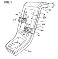
- FIG. 1 is a view showing a center cluster 1 to which the in-car operation display device according to the present invention is provided.
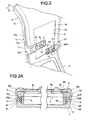
- FIG. 2 is an explanatory enlarged view of a sloping portion 1a of the center cluster 1 as viewed from an upper-left side of FIG. 1 .
- the sloping portion 1a extends in a car-width direction and also in an up-down direction of the center cluster 1 of FIG. 1 . With respect to the car-width direction, this sloping portion 1a is arranged on a center portion of a car-interior rear surface (not shown) of an instrument panel (not shown).
- the center cluster 1 includes an upper attachment portion 1b and a lower attachment portion 1c.
- the upper attachment portion 1b is continuous with an upper end of the sloping portion 1a, and extends in a frontward direction.
- the upper attachment portion 1b is provided in a connected row arrangement with an upper portion of the car-width-directional center portion of the instrument panel (not shown).
- the lower attachment portion 1c is continuous with a lower end of the sloping portion 1a, and extends in a rearward direction. This lower attachment portion 1c is provided in a connected row arrangement with a center console (not shown).
- the center cluster 1 further includes a lower cluster panel (lower cluster member) 2 and an upper cluster panel (upper cluster member) 3.
- the lower cluster panel 2 and the upper cluster panel 3 are coupled and fixed to each other, and are separable from each other.
- a latching hook, a fixing screw or the like is used as a coupling means for coupling and fixing these lower cluster panel 2 and upper cluster panel 3 to each other.
- the lower cluster panel 2 includes a left-side wall 2L and a right-side wall 2R.
- the left-side wall 2L includes a left-guide-side wall portion 2GL at a location corresponding to the sloping portion 1a.
- the left-guide-side wall portion 2GL has a multilevel portion (multilevel concave).
- the right-side wall 2R includes a right-guide-side wall portion 2GR at a location corresponding to the sloping portion 1a.
- the right-guide-side wall portion 2GR has a multilevel portion (multilevel concave).
- a left sensor substrate 4L is fixed to the lower cluster panel 2.
- This left sensor substrate 4L is placed in parallel with the left-guide-side wall portion 2GL such that a space exists between the left sensor substrate 4L and the left-guide-side wall portion 2GL.
- a right sensor substrate 4R is fixed to the lower cluster panel 2.
- This right sensor substrate 4R is placed in parallel with the right-guide-side wall portion 2GR such that a space exists between the right sensor substrate 4R and the right-guide-side wall portion 2GR.
- a lower-left sensing section Ls1, a middle-left sensing section Ls2 and an upper-left sensing section Ls3 are mounted on the left sensor substrate 4L, as position sensors.
- the lower-left sensing section Ls1, the middle-left sensing section Ls2 and the upper-left sensing section Ls3 are respectively placed at one end portion (lower end portion), a central portion and another end portion (upper end portion) of the left sensor substrate 4L, along an extending direction of the left-guide-side wall portion 2GL.
- a lower-right sensing section Rs1, a middle-right sensing section Rs2 and an upper-right sensing section Rs3 are mounted on the right sensor substrate 4R, as position sensors.
- the lower-right sensing section Rs1, the middle-right sensing section Rs2 and the upper-right sensing section Rs3 are respectively placed at one end portion (lower end portion), a central portion and another end portion (upper end portion) of the right sensor substrate 4R, along an extending direction of the right-guide-side wall portion 2GR.
- a known position sensor such as a contact-type sensor, a switch-type sensor, a photoelectric-type sensor and a proximity-switch-type sensor can be used.
- a first linear potentiometer may be used as a left position sensor in place of the sensing sections Ls1 to Ls3, and a second linear potentiometer may be used as a right position sensor in place of the sensing sections Rs1 to Rs3.
- the first embodiment exemplifies a case that the sensing sections Ls1 to Ls3 and the sensing sections Rs1 to Rs3 are used.
- a display window 3a is formed in the upper cluster panel 3 at a location corresponding to the sloping portion 1a.
- a touch display 5 is attached to the upper cluster panel 3 as a display unit (displaying means) such that a display screen 5a of the touch display 5 is exposed through (i.e., faces) the display window 3a.
- the touch display 5 is constituted by a liquid crystal display instrument whose surface includes a touch panel, and the like.
- a left guide slit GsL is formed between the left-guide-side wall portion 2GL of the lower cluster panel 2 and a left-side portion of the upper cluster panel 3.
- the left guide slit GsL extends in the up-down direction as a guide portion and is located at the sloping portion 1a.
- a right guide slit GsR is formed between the right-guide-side wall portion 2GR of the lower cluster panel 2 and a right-side portion of the upper cluster panel 3.
- the right guide slit GsR extends in the up-down direction as the guide portion and is located at the sloping portion 1a.
- a first switch plate SpL is provided at a left portion of the touch display 5 as a first switch panel (operating portion) which is also referred to as a left slide-operation plate (left slide-operation panel).
- a second switch plate SpR is provided at a right portion of the touch display 5 as a second switch panel (operating portion) which is also referred to as a right slide-operation plate (right slide-operation panel).
- the first switch plate SpL is denoted by “Slide SW(L) plate”
- the second switch plate SpR is denoted by “Slide SW(R) plate”.
- the first and second switch plates SpL, SpR are used as operating portions for changing car-installed functions and images of the car-installed functions displayed on the display screen 5a.
- Each of the first and second switch plates SpL, SpR is formed by a transparent or semitransparent panel made of an insulating resin material.
- the first switch plate SpL includes a left operating-plate portion (left operating-panel portion) 6L and a panel main body (reference sign omitted).
- the left operating-plate portion 6L is provided as the operating portion, and extends along the display screen 5a such that a tip of the left operating-plate portion 6L reaches a center of the display screen 5a with respect to the car-width direction.
- the panel main body is formed in a substantially L-shape from a side plate portion 7L which is continuous with (i.e. is provided in a connected row arrangement with) one end portion of the left operating-plate portion 6L. As shown in FIG.
- the first switch plate SpL further includes a guide plate portion 8L and a contact plate portion 9L.
- the guide plate portion 8L is formed integrally with the side plate portion 7L, and is passed through the left guide slit GsL.
- the contact plate portion 9L is formed integrally with the guide plate portion 8L, and is located between the left-guide-side wall portion 2GL and the left sensor substrate 4L.
- the left operating-plate portion 6L is formed integrally with a pair of touch-sensor protrusions 10 and 11 (switch protrusions for touch detection) and a touch-sensor protrusion 12 (switch protrusion for touch detection).
- the pair of touch-sensor protrusions 10 and 11 are located away from each other by a space in the car-width direction.
- Each of the pair of touch-sensor protrusions 10 and 11 is in the form of flat trapezoid.
- the touch-sensor protrusion 12 is in the form of dial protrusion, and is located between the pair of touch-sensor protrusions 10 and 11. As shown in FIG.
- a colored left-pointing mark ML is applied to (printed on) the touch-sensor protrusion 10
- a colored right-pointing mark MR is applied to the touch-sensor protrusion 11.
- Each of the colored left-pointing mark ML and the colored right-pointing mark MR is in a triangular shape and indicates its operating direction.
- a plurality of grooves 12a are formed in a peripheral surface (outer circumferential surface) of the touch-sensor protrusion 12.
- the plurality of grooves 12a extend in a protruding direction of the touch-sensor protrusion 12, and are provided at intervals in a circumferential direction of the touch-sensor protrusion 12.
- touch sensor portions 12b are provided between any adjacent two of the plurality of grooves 12a.
- transparent electrodes (terminals) 10a and 11a are respectively provided on base ends of the touch-sensor protrusions 10 and 11.
- a transparent pattern wiring 10b is provided in the first switch plate SpL, and extends from the transparent electrode 10a to the contact plate portion 9L.
- a transparent pattern wiring 11b is provided in the first switch plate SpL, and extends from the transparent electrode 11a to the contact plate portion 9L.
- a plurality of transparent electrodes (terminals) 12c are provided respectively inside the plurality of touch sensor portions 12b of the touch-sensor protrusion 12.
- Transparent pattern wirings 12d are provided in the first switch plate SpL, and respectively extend from the plurality of transparent electrodes 12c to the contact plate portion 9L.
- the transparent electrodes 10a, 11a and 12c and the transparent pattern wirings 10b, 11b and 12d are formed by means of pattern printing (printed wiring) before forming the touch-sensor protrusions 10 and 11 and the touch sensor portions 12b. That is, in this embodiment, the touch-sensor protrusions 10, 11 and 12 can be formed after forming the transparent electrodes 10a, 11a and 12c and the transparent pattern wirings 10b, 11b and 12d.
- Click catching mechanisms are provided in the lower cluster panel 2 at locations corresponding to the respective sensing sections Ls1, Ls2 and Ls3. Each of the click catching mechanisms catches or stops the first switch plate SpL by click stop. Each of the click catching mechanisms can be constructed by using a known mechanism such as a concave-and-convex and a plate-spring-and-depression.
- the second switch plate SpR includes a right operating-plate portion (right operating-panel portion) 6R and a panel main body (reference sign omitted).
- the right operating-plate portion 6R is provided as the operating portion, and extends along the display screen 5a such that a tip of the right operating-plate portion 6R reaches the center of the display screen 5a with respect to the car-width direction.
- the panel main body is formed in a substantially L-shape from a side plate portion 7R which is continuous with (i.e. is provided in a connected row arrangement with) one end portion of the right operating-plate portion 6R. As shown in FIG.
- the second switch plate SpR further includes a guide plate portion 8R and a contact plate portion 9R.
- the guide plate portion 8R is formed integrally with the side plate portion 7R, and is passed through the right guide slit GsR.
- the contact plate portion 9R is formed integrally with the guide plate portion 8R, and is located between the right-guide-side wall portion 2GR and the right sensor substrate 4R.
- the right operating-plate portion 6R includes a pair of touch-sensor protrusions 13 and 14 (switch protrusions for touch detection) in a tip portion of the right operating-plate portion 6R.
- the pair of touch-sensor protrusions 13 and 14 are located away from each other by a space in the up-down direction.
- Each of the pair of touch-sensor protrusions 13 and 14 is in the form of flat trapezoid.
- a base end portion of the right operating-plate portion 6R is formed integrally with a touch-sensor protrusion 15 (switch protrusion for touch detection).
- the touch-sensor protrusion 15 is in the form of dial protrusion. As shown in FIG.
- a colored up-pointing mark MU is applied to (printed on) the touch-sensor protrusion 13, and a colored down-pointing mark MD is applied to the touch-sensor protrusion 14.
- Each of the colored up-pointing mark MU and the colored down-pointing mark MD is in a triangular shape and indicates its operating direction.
- a plurality of grooves 15a are formed in a peripheral surface (outer circumferential surface) of the touch-sensor protrusion 15.
- the plurality of grooves 15a extend in a protruding direction of the touch-sensor protrusion 15, and are provided at intervals in a circumferential direction of the touch-sensor protrusion 15. Thereby, touch sensor portions 15b are provided between any adjacent two of the plurality of grooves 15a.
- transparent electrodes (terminals) 13a and 14a are respectively provided on base ends of the touch-sensor protrusions 13 and 14.
- a transparent pattern wiring 13b is provided in the second switch plate SpR, and extends from the transparent electrode 13a to the contact plate portion 9R.
- a transparent pattern wiring 14b is provided in the second switch plate SpR, and extends from the transparent electrode 14a to the contact plate portion 9R.
- a plurality of transparent electrodes (terminals) 15c are provided respectively inside the plurality of touch sensor portions 15b of the touch-sensor protrusion 15.
- Transparent pattern wirings 15d are provided in the second switch plate SpR, and respectively extend from the plurality of transparent electrodes 15c to the contact plate portion 9R.
- the transparent electrodes and the transparent pattern wirings are formed by means of pattern printing (printed wiring) before forming the touch-sensor protrusions 13 and 14 and the touch sensor portions 15b. That is, in this embodiment, the touch-sensor protrusions 13 and 14 and the touch sensor portions 15b can be formed after forming the transparent electrodes and the transparent pattern wirings.
- Click catching mechanisms are provided in the lower cluster panel 2 at locations corresponding to the respective sensing sections Rs1, Rs2 and Rs3. Each of the click catching mechanisms catches or stops the second switch plate SpR by click stop. Each of the click catching mechanisms can be constructed by using a known mechanism such as a concave-and-convex and a plate-spring-and-depression.
- the transparent pattern wirings 10b, 11b and 12d are connected with flexible wirings (not shown) at the contact plate portion 9L. Thereby, the transparent pattern wirings 10b, 11b and 12d are connected through the flexible wirings to an arithmetic control circuit 20. Hence, the arithmetic control circuit 20 receives operations of the touch-sensor protrusions 10, 11 and 12 of the first switch plate SpL.
- the transparent pattern wirings 13b, 14b and 15d are connected with flexible wirings (not shown) at the contact plate portion 9R. Thereby, the transparent pattern wirings 13b, 14b and 15d are connected through the flexible wirings to the arithmetic control circuit 20.
- the arithmetic control circuit 20 receives operations of the touch-sensor protrusions 13, 14 and 15 of the second switch plate SpR. Moreover, the arithmetic control circuit 20 performs a display control of the touch display 5 and operational controls of a navigation control section 21, an air-conditioner control section 22 and an audio control section 23.
- the arithmetic control circuit 20 When electric power is turned on by an accessary switch (ACC, not shown) of the car, the arithmetic control circuit 20 receives outputs of the respective sensing sections Ls1 to Ls3 which are the position sensors. At the same time, the arithmetic control circuit 20 also receives outputs of the respective sensing sections Rs1 to Rs3 which are the position sensors. Then, the arithmetic control circuit 20 starts to control.
- ACC accessary switch
- the lower-left sensing section Ls1 which is the position sensor detects the contact plate portion 9L of the first switch plate SpL when the first switch plate SpL is positioned at a lower end portion of the touch display 5. Then, the lower-left sensing section Ls1 outputs this detection signal (to the arithmetic control circuit 20).
- the middle-left sensing section Ls2 which is the position sensor detects the contact plate portion 9L of the first switch plate SpL when the first switch plate SpL is positioned at a central portion of the touch display 5 with respect to the up-down direction. Then, the middle-left sensing section Ls2 outputs this detection signal (to the arithmetic control circuit 20).
- the upper-left sensing section Ls3 which is the position sensor detects the contact plate portion 9L of the first switch plate SpL when the first switch plate SpL is positioned at an upper end portion of the touch display 5. Then, the upper-left sensing section Ls3 outputs this detection signal (to the arithmetic control circuit 20).
- the lower-right sensing section Rs1 which is the position sensor detects the contact plate portion 9R of the second switch plate SpR when the second switch plate SpR is positioned at the lower end portion of the touch display 5. Then, the lower-right sensing section Rs1 outputs this detection signal (to the arithmetic control circuit 20).
- the middle-right sensing section Rs2 which is the position sensor detects the contact plate portion 9R of the second switch plate SpR when the second switch plate SpR is positioned at the central portion of the touch display 5 with respect to the up-down direction. Then, the middle-right sensing section Rs2 outputs this detection signal (to the arithmetic control circuit 20).
- the upper-right sensing section Rs3 which is the position sensor detects the contact plate portion 9R of the second switch plate SpR when the second switch plate SpR is positioned at the upper end portion of the touch display 5. Then, the upper-right sensing section Rs3 outputs this detection signal (to the arithmetic control circuit 20).
- the detection signals derived from the respective sensing sections Ls1-Ls3 and Rs1-Rs3 are inputted to the arithmetic control circuit 20.
- a car-installed function that is operated by the first switch plate SpL is an audiovisual function (audio device).
- An image for operating the audio device is shown on the touch display 5.
- fast-forward operation forward quick scan
- fast-reverse operation reverse quick scan
- a volume level of sound can be increased or decreased.
- a driver can find (recognize) the touch-sensor protrusions 10, 11 and 12 of the first switch plate SpL by touch feeling. Therefore, the driver can operate (manipulate) the touch-sensor protrusions 10, 11 and 12 of the first switch plate SpL without visually identifying the touch-sensor protrusions 10, 11 and 12.
- a car-installed function that is operated by the second switch plate SpR is an air-conditioning function (air conditioner).
- An image for operating the air conditioner is shown on the touch display 5.
- a temperature setting can be turned up or down.
- rotational speed of a blast fan can be increased or decreased so that a strength of air blow can be adjusted.
- a driver can find (recognize) the touch-sensor protrusions 13, 14 and 15 of the second switch plate SpR by touch feeling. Therefore, the driver can operate (manipulate) the touch-sensor protrusions 13, 14 and 15 of the second switch plate SpR without visually identifying the touch-sensor protrusions 13, 14 and 15.
- the car-installed function that is operated by the first switch plate SpL is the audiovisual function (audio device), while the car-installed function that is operated by the second switch plate SpR is the air-conditioning function (air conditioner).
- the car-installed functions which are operated by the first switch plate SpL and the second switch plate SpR may be the other functions (the other devices).
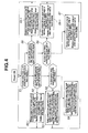
- the arithmetic control circuit 20 determines a position of the first switch plate SpL by selecting from the lower end portion, the up-down-directional central portion and the upper end portion of the touch display 5. In the same manner, the arithmetic control circuit 20 determines a position of the second switch plate SpR by selecting from the lower end portion, the up-down-directional central portion and the upper end portion of the touch display 5. Moreover, on the basis of these detection signals, the arithmetic control circuit 20 starts a control action as shown by a flowchart of FIG. 4 .
- the first switch plate SpL exists at an up-down-directional intermediate portion of the touch display 5 as shown in FIG. 5
- the first switch plate SpL can slide in the upper direction and also in the downward direction as shown by arrows A2 and A3.
- the second switch plate SpR exists at the lower end portion of the touch display 5 as shown in FIG. 5
- the second switch plate SpR can slide in the upper direction shown by an arrow A4.
- the arithmetic control circuit 20 judges whether or not at least one of the first switch plate SpL and the second switch plate SpR (slide switch SW(L or R)) is positioned at the upper end of the touch display 5, at step S1. If any of the first switch plate SpL and the second switch plate SpR is not positioned at the upper end of the touch display 5, the program proceeds to step S2. If at least one of the first switch plate SpL and the second switch plate SpR is positioned at the upper end of the touch display 5, the program proceeds to step S5.
- step S2 the arithmetic control circuit 20 judges whether or not both of the first switch plate SpL and the second switch plate SpR are positioned at the lower end of the touch display 5. If both of the first switch plate SpL and the second switch plate SpR are positioned at the lower end of the touch display 5, the program proceeds to step S 2-1. If at least one of the first switch plate SpL and the second switch plate SpR is not positioned at the lower end of the touch display 5, the program proceeds to step S3.
- both of the first switch plate SpL and the second switch plate SpR exist at the lower end of the touch display 5.
- the tip (right end) of the left operating-plate portion 6L of the first switch plate SpL faces the tip (left end) of the right operating-plate portion 6R of the second switch plate SpR to have a minute space between the tip of the left operating-plate portion 6L and the tip of the right operating-plate portion 6R.
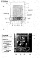
- the arithmetic control circuit 20 calls up (or retrieves) image information from the navigation control section 21. From this image information, the arithmetic control circuit 20 obtains a navigation image as shown in FIG. 6A(b) , and displays this navigation image (image size: large) as a content A of FIG. 6A(a) . That is, the navigation image is displayed over a range from upper ends of the first and second switch plates SpL and SpR (slide switches SW(L and R)) to the upper end of the touch display 5.
- the arithmetic control circuit 20 calls up (or retrieves) audio-control information which is used for controlling the audio device, from the audio control section 23. From this audio-control information, the arithmetic control circuit 20 obtains an audio-device-operation image for operating the audio device as show in FIG. 6A(b) , and displays this audio-device-operation image (image size: minimum) as a content B of FIG. 6A(a) . That is, the audio-device-operation image is displayed over a range from the lower end of the touch display 5 to the upper end of the first switch plate SpL (slide switch SW(L)).
- the arithmetic control circuit 20 calls up (or retrieves) air-conditioner information which is used for controlling the air conditioner, from the air-conditioner control section 22. From this air-conditioner information, the arithmetic control circuit 20 obtains an air-conditioner-operation image for operating the air conditioner as show in FIG. 6A(b) , and displays this air-conditioner-operation image (image size: minimum) as a content C of FIG. 6A(a ). That is, the air-conditioner-operation image is displayed over a range from the lower end of the touch display 5 to the upper end of the second switch plate SpR (slide switch SW(R)).
- the minimum contents B and C are displayed respectively in left and right portions of the lower end portion of the touch display 5 such that the content B and the content C are arranged side by side in a line with respect to the right-left direction.
- the content A having a large size is displayed above the contents B and C.
- the first switch plate SpL which is provided for operating the content B is located on, i.e., overlaps with (the image of) the content B
- the second switch plate SpR which is provided for operating the content C is located on, i.e., overlaps with (the image of) the content C.
- the minimum contents B and C are displayed respectively in left and right portions of in the lower end portion of the touch display 5 such that the content B and the content C are arranged side by side.
- the driver can operate the touch-sensor protrusions 10, 11 and 12 of the first switch plate SpL without visually identifying the content B because the driver can find (recognize) the touch-sensor protrusions 10, 11 and 12 of the first switch plate SpL by touch feeling.
- the fast-forward operation forward quick scan
- the fast-reverse operation reverse quick scan
- the volume level of sound can be increased or decreased by changing a touch position among the plurality of touch sensor portions 12b of the touch-sensor protrusion 12.
- the driver can operate the touch-sensor protrusions 13, 14 and 15 of the second switch plate SpR without visually identifying the content C because the driver can find (recognize) the touch-sensor protrusions 13, 14 and 15 of the second switch plate SpR by touch feeling.
- the temperature setting can be turned up or down by operating the touch-sensor protrusions 13 and 14 of the second switch plate SpR, and moreover, the rotational speed of the blast fan can be increased or decreased to adjust the strength of air blow by changing a touch position among the plurality of touch sensor portions 15b of the touch-sensor protrusion 15.
- the arithmetic control circuit 20 judges whether or not the first switch plate SpL (slide switch SW(L)) is positioned above (i.e. takes an upper position relative to) the second switch plate SpR (slide switch SW(R)).
- step S3-1 If the first switch plate SpL is positioned at the up-down-directional central portion of the touch display 5, the program proceeds to step S3-1.
- step S4 if the first switch plate SpL is not positioned at the up-down-directional central portion of the touch display 5, the program proceeds to step S4.
- the arithmetic control circuit 20 calls up (retrieves) image information from the navigation control section 21. From this image information, the arithmetic control circuit 20 obtains a navigation image as exemplified in FIG. 6A(b) , and displays this navigation image as the content A over a range from the upper end of the first switch plate SpL to the upper end of the touch display 5.
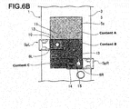
- the arithmetic control circuit 20 calls up (retrieves) audio-control information which is used for controlling the audio device, from the audio control section 23. From this audio-control information, the arithmetic control circuit 20 obtains an audio-device-operation image for operating the audio device as exemplified in FIG. 6A(b) , and displays this audio-device-operation image as the content B of FIG. 6B . That is, the audio-device-operation image is displayed over a range from the upper end of the first switch plate SpL (slide switch SW(L)) to the upper end of the second switch plate SpR (slide switch SW(R)).
- the arithmetic control circuit 20 calls up (retrieves) air-conditioner information which is used for operating the air conditioner, from the air-conditioner control section 22. From this air-conditioner information, the arithmetic control circuit 20 obtains an air-conditioner-operation image for operating the air conditioner as exemplified in FIG. 6A(b) , and displays this air-conditioner-operation image as the content C of FIG. 6B . That is, the air-conditioner-operation image is displayed over a range from the upper end of the second switch plate SpR (slide switch SW(R)) to the lower end of the touch display 5 as shown in FIG. 6B .
- the contents A and B each having a medium size and the content C having a small size are displayed sequentially from above, on the touch display 5.
- the contents A and B are easy to recognize.
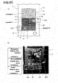
- the arithmetic control circuit 20 calls up (retrieves) image information from the navigation control section 21. From this image information, the arithmetic control circuit 20 obtains a navigation image as exemplified in FIG. 6A(b) , and displays this navigation image as the content A of FIG. 6C . That is, the navigation image is displayed over a range from the upper end of the second switch plate SpR (slide switch SW(R)) to the upper end of the touch display 5.
- the arithmetic control circuit 20 calls up (retrieves) air-conditioner information which is used for operating the air conditioner, from the air-conditioner control section 22. From this air-conditioner information, the arithmetic control circuit 20 obtains an air-conditioner-operation image for operating the air conditioner as exemplified in FIG. 6A(b) , and displays this air-conditioner-operation image as the content C of FIG. 6C . That is, the air-conditioner-operation image is displayed over a range from the upper end of the first switch plate SpL (slide switch SW(L)) to the upper end of the second switch plate SpR (slide switch SW(R)) as shown in FIG. 6C .
- the arithmetic control circuit 20 calls up (or retrieves) audio-control information which is used for controlling the audio device, from the audio control section 23. From this audio-control information, the arithmetic control circuit 20 obtains an audio-device-operation image for operating the audio device as exemplified in FIG. 6A(b ), and displays this audio-device-operation image as the content B of FIG. 6C . That is, the audio-device-operation image is displayed over a range from the upper end of the first switch plate SpL (slide switch SW(L)) to the lower end of the touch display 5, as shown in FIG. 6C .
- the contents A and C each having the medium size and the content B having the small size are displayed sequentially from above, on the touch display 5. In this pattern, the contents A and C are easy to recognize.
- step S5 The following image-display controls are performed after step S5 although displayed patterns of the contents A to C are omitted in the drawings.
- the arithmetic control circuit 20 judges whether or not both of the first switch plate SpL (slide switch SW(L)) and the second switch plate SpR (slide switch SW(R)) are positioned at the upper end of the touch display 5.
- step S5-1 If it is determined that both of the first switch plate SpL and the second switch plate SpR are positioned at the upper end of the touch display 5, the program proceeds to step S5-1. If it is determined that at least one of the first switch plate SpL and the second switch plate SpR is not positioned at the upper end of the touch display 5, the program proceeds to step S6.
- the arithmetic control circuit 20 calls up (retrieves) image information from the navigation control section 21. From this image information, the arithmetic control circuit 20 obtains a navigation image as exemplified in FIG. 6A(b) , and displays this navigation image (image size: maximum) as the content A. That is, the navigation image is displayed over a range from lower ends of the first and second switch plates SpL and SpR (slide switches SW(L and R)) to the lower end of the touch display 5.
- the arithmetic control circuit 20 calls up (or retrieves) audio-control information which is used for controlling the audio device, from the audio control section 23. From this audio-control information, the arithmetic control circuit 20 obtains an audio-device-operation image for operating the audio device as exemplified in FIG. 6A(b) , and displays this audio-device-operation image (image size: minimum) as the content B. That is, the audio-device-operation image is displayed over a range from the upper end of the touch display 5 to the lower end of the first switch plate SpL.
- the arithmetic control circuit 20 calls up (or retrieves) air-conditioner information which is used for operating the air conditioner, from the air-conditioner control section 22. From this air-conditioner information, the arithmetic control circuit 20 obtains an air-conditioner-operation image for operating the air conditioner as exemplified in FIG. 6A(b) , and displays this air-conditioner-operation image (image size: minimum) as the content C. That is, the air-conditioner-operation image is displayed over a range from the upper end of the touch display 5 to the lower end of the second switch plate SpR.
- the minimum contents B and C are displayed respectively in left and right portions of the upper end portion of the touch display 5 such that the content B and the content C are arranged side by side in a line with respect to the right-left direction.
- the content A having a large size is displayed below the contents B and C. In this pattern, the content A is easy to recognize.
- the arithmetic control circuit 20 judges whether or not the first switch plate SpL (slide switch SW(L)) is positioned at the upper end portion of the touch display 5.
- step S6-1 If the first switch plate SpL is positioned at the upper end portion of the touch display 5, the program proceeds to step S6-1.
- step S7 if the first switch plate SpL is not positioned at the upper end portion of the touch display 5, the program proceeds to step S7.
- step S6 the first switch plate SpL exists at the upper end portion of the touch display 5 whereas the second switch plate SpR does not exist at the upper end portion of the touch display 5.
- the arithmetic control circuit 20 calls up (retrieves) audio-control information which is used for controlling the audio device, from the audio control section 23. From this audio-control information, the arithmetic control circuit 20 obtains an audio-device-operation image for operating the audio device as exemplified in FIG. 6A(b) . Then, the arithmetic control circuit 20 displays this audio-device-operation image as the content B over a range from the upper end of the touch display 5 to the upper end of the second switch plate SpR.
- the arithmetic control circuit 20 calls up (retrieves) air-conditioner information which is used for operating the air conditioner, from the air-conditioner control section 22. From this air-conditioner information, the arithmetic control circuit 20 obtains an air-conditioner-operation image for operating the air conditioner as exemplified in FIG. 6A(b) . Then, the arithmetic control circuit 20 displays this air-conditioner-operation image as the content C over a range from the upper end of the second switch plate SpR to the lower end of the touch display 5.
- the contents B and C each having a medium size are displayed sequentially from above, on the touch display 5.
- the contents B and C are easy to recognize.
- step S6 the first switch plate SpL does not exist at the upper end portion of the touch display 5 whereas the second switch plate SpR exists at the upper end portion of the touch display 5.
- the arithmetic control circuit 20 calls up (retrieves) air-conditioner information which is used for operating the air conditioner, from the air-conditioner control section 22. From this air-conditioner information, the arithmetic control circuit 20 obtains an air-conditioner-operation image for operating the air conditioner as exemplified in FIG. 6A(b) . Then, the arithmetic control circuit 20 displays this air-conditioner-operation image as the content C over a range from the upper end of the first switch plate SpL to the upper end of the touch display 5.
- the arithmetic control circuit 20 calls up (retrieves) audio-control information which is used for controlling the audio device, from the audio control section 23. From this audio-control information, the arithmetic control circuit 20 obtains an audio-device-operation image for operating the audio device as exemplified in FIG. 6A(b) . Then, the arithmetic control circuit 20 displays this audio-device-operation image as the content B over a range from the upper end of the first switch plate SpL to the lower end of the touch display 5.
- the contents C and B each having a medium size are displayed sequentially in this order from above, on the touch display 5.
- the contents B and C are easy to recognize.
- the sensing sections Ls1 to Ls3 are provided for sensing the position of the first switch plate SpL with respect to the up-down direction.
- the sensing sections Rs1 to Rs3 are provided for sensing the position of the second switch plate SpR with respect to the up-down direction.
- the configuration according to the present invention is not necessarily limited to this.
- the up-down-directional position of the first switch plate SpL and/or the second switch plate SpR can be continuously sensed by a linear position sensor such as the above-mentioned linear potentiometer and a linear scale.
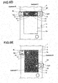
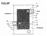
- FIGS. 6D to 6F Views as shown in FIGS. 6D to 6F may be adopted when at least one of the first switch plate SpL and the second switch plate SpR is positioned at the upper end portion of the touch display 5.
- the content B is displayed over a range from the lower end of the first switch plate SpL to the upper end of the touch display 5
- the content C is displayed over a range from the lower end of the second switch plate SpR to the upper end of the touch display 5.
- no image may be displayed over a range from the lower ends of the first and second switch plates SpL, SpR to the lower end of the touch display 5.
- the above-mentioned content A may be displayed over the range from the lower ends of the first and second switch plates SpL, SpR to the lower end of the touch display 5.
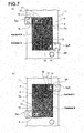
- FIGS. 7(a) and 7(b) Views as shown in FIGS. 7(a) and 7(b) may be adopted, in the case that one of the first switch plate SpL and the second switch plate SpR is positioned at the upper end portion of the touch display 5 and another of the first switch plate SpL and the second switch plate SpR is positioned at the lower end portion of the touch display 5.
- the content B can be displayed on an upper portion of the touch display 5 so that the content C is displayed on a lower portion of the touch display 5.
- the content C can be displayed on an upper portion of the touch display 5 so that the content B is displayed on a lower portion of the touch display 5.
- the first switch plate SpL for operating the content B is located on, i.e., overlaps with (the image of) the content B whereas the second switch plate SpR for operating the content C is located on, i.e., overlaps with (the image of) the content C.
- the position of each of the first switch plate SpL and the second switch plate SpR with respect to the up-down direction is continuously sensed by a potentiometer, a linear scale or the like.
- the arithmetic control circuit 20 displays the image of the content A over a range from the upper end of the first switch plate SpL to the upper end of the touch display 5, displays the image of the content B over a range from the upper end of the first switch plate SpL to the upper end of the second switch plate SpR, and displays the image of the content C over a range from the upper end of the second switch plate SpR to the lower end of the touch display 5.
- the first switch plate SpL is operatively moved in the upper direction as shown by an arrow A5.
- the arithmetic control circuit 20 gradually reduces the image of the content A and gradually enlarges the image of the content B as shown in FIGS. 8B and 8C .
- the arithmetic control circuit 20 removes (i.e. does not display) the image of the content A and maximizes the image of the content B.
- the audio-device-operation image of the content B can be displayed over a range from the upper end of the second switch plate SpR to the upper end of the touch display 5 so that the air-conditioner-operation image of the content C is displayed over a range from the upper end of the second switch plate SpR to the lower end of the touch display 5.
- the air-conditioner-operation image of the content C can be displayed over a range from the upper end of the first switch plate SpL to the upper end of the touch display 5 so that the audio-device-operation image of the content B is displayed over a range from the upper end of the first switch plate SpL to the lower end of the touch display 5.
- the first switch plate SpL and the second switch plate SpR are respectively provided at both sides of the touch display 5.
- the configuration according to the present invention is not necessarily limited to this.
- the first switch plate SpL may be provided by omitting the second switch plate SpR of the first embodiment.
- the left operating-plate portion 6L of the first switch plate SpL may be set to have a length equal to an entire width of the touch display 5 with respect to the right-left direction.
- the touch-sensor protrusions 13 and 14 as provided to the second switch plate SpR of the first embodiment may be provided to the left operating-plate portion 6L of the first switch plate SpL in addition to the touch-sensor protrusions 10, 11 and 12 provided to the left operating-plate portion 6L.
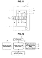
- the arithmetic control circuit 20 shown in FIG. 12 receives touch-operation signals derived from the touch-sensor protrusions 10, 11, 12, 13 and 14 of the first switch plate SpL. Moreover, in this embodiment, the up-down-directional position of the first switch plate SpL can be continuously (in a stepless manner) detected by a linear position sensor (Slide-SW(L) position sensor) 30 such as a linear potentiometer and a linear sensor. Position signals detected by this linear position sensor (Slide-SW(L) position sensor) 30 are inputted into the arithmetic control circuit 20.
- a linear position sensor Slide-SW(L) position sensor
- the arithmetic control circuit 20 carries out the display control of the touch display 5 for the respective contents on the basis of the detected position signals, and controls or actuates the navigation control section 21, the air-conditioner control section 22 and the audio control section 23. Moreover, the arithmetic control circuit 20 carries out the operational controls and the display controls for the functions of car-installed devices corresponding to the contents of the touch display 5, on the basis of the touch-operation signals derived from the touch-sensor protrusions 10, 11, 12, 13 and 14.
- the arithmetic control circuit 20 displays the content B over an entire range of the touch display 5 when the first switch plate SpL is positioned at the upper end of the touch display 5 as shown in FIG. 13A .
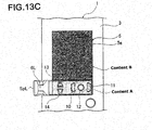
- the arithmetic control circuit 20 displays the content A over a range from the upper end of the first switch plate SpL to the upper end of the touch display 5 and displays the content B over a range from the upper end of the first switch plate SpL to the lower end of the touch display 5.
- the arithmetic control circuit 20 displays the content B over a range from the upper end of the first switch plate SpL to the upper end of the touch display 5 and displays the content A over a range from the upper end of the first switch plate SpL to the lower end of the touch display 5.
- the content B has a relatively large size whereas the content A has a minimum size.
- the plurality of operational buttons can be selected by operating the touch-sensor protrusions 10 and 11.
- the plurality of operational menus can be selected by operating the touch-sensor protrusions 13 and 14.
- the content B is the navigation image
- the content A is the audio-device-operation image or the air-conditioner-operation image.
- a common switching structure of touch display operational frames and/or operational buttons each of which indicates its title are merely displayed on a screen of the touch display.
- the operational frames and/or operational buttons of the touch display are operated by touch operations so that a screen view (displayed image) is changed and/or peripheral devices corresponding to the screen view are operated.
- many operational menus can be provided in a limited area and also can be flexibly arranged.
- the driver tends to gaze or watch the screen in order to find a desired operational menu because there is no concave or convex on the screen of the touch display. Hence, it is difficult to operate the touch display while driving the car.
- an in-car operation display device is constituted by a liquid crystal display instrument or the like and hard switches (hard SW) which are placed around the liquid crystal display instrument and which are used for operating a car-installed device(s)
- the driver gropes for a desired switch among the hard switches and thereby can find the desired switch in a short time by tactile perception of shapes of the hard switches.
- the driver can operate the car-installed device.
- the hard switches cannot be moved to a location convenient for the driver to use because the hard switches (hard SW) are fixed to predetermined spots. If trying to provide many hard switches at the convenient location, the number of components becomes large.
- the first switch plate SpL and the second switch plate SpR (slide switches SW(L and R)) which are transparent are respectively provided on the left and right portions of the touch display 5 as touch panels.
- These first switch plate SpL and second switch plate SpR can move (slide) in the upper and lower directions within a view region of the touch display 5.
- each of the first switch plate SpL and the second switch plate SpR is formed with the touch-sensor protrusions 10-15 which are concave-convex-shaped switches, the driver can recognize locations of the touch-sensor protrusions 10-15 without visual check (see FIG. 2 ). Because each of the first switch plate SpL and the second switch plate SpR (slide switches SW(L and R)) is made of a transparent material, the driver can see the displayed contents of the touch display 5 through the first switch plate SpL or the second switch plate SpR. The contents displayed on the touch display 5 can be changed by moving the first switch plate SpL and the second switch plate SpR in the upper and lower directions shown by the arrows A2 and A3 (see FIG. 5 ).
- the transparent first and second switch plates are provided, the locations of switches which are displayed on the touch display 5 can be found by convexoconcave. Therefore, merit of the hard switch (i.e., an ability of operating without visual check) can be added without impairing merit of the touch display 5 (i.e., an ability of freely changing design and image position). Accordingly, the driver can indirectly operate the touch display 5 even while driving the car.
- the driver can move each of the first and second switch plates (slide switches SW(L and R)) to a desired position of the driver.
- this switch plate silica switch SW
- the view of the touch display 5 is varied so that display areas (image ranges) of the respective contents expand or contract to follow the movement. Therefore, functions of a content which is desired to be used by the driver and its display area are expanded whereas functions of a content which is not desired to be used and its display area are minimized. Thereby, a screening (separation) among much information becomes easy (see FIG. 5 ).
- the display areas (image ranges) of the three contents A to C are varied in dependence upon positions of the two slide switches SW(L and R). That is, the display areas are determined according to a positional relation between the slide switch SW(L) and the slide switch SW(R).
- the content A is always displayed on the upper portion of the display screen unless the slide switch SW(L) or the slide switch SW(R) is brought to an uppermost portion of the display screen 5a.
- the content B is displayed from the upper end portion of the slide switch SW(L) to the upper end of the slide switch SW(R) or to the lower end (of the display screen) of the touch display 5.
- the content C is displayed from the upper end portion of the slide switch SW(R) to the to the upper end of the slide switch SW(L) or to the lower end of the touch display 5. It is noted that the other detailed operations which are less frequently used are conducted by directly touching the touch display 5.
- the transparent first and second switch plates are provided, the locations of respective switches which are displayed on the touch display 5 can be found by convexoconcave. Therefore, merit of the hard switch (i.e., the ability of operating without visual check) can be added without impairing merit of the touch display 5 (i.e., the ability of freely changing design and image position). Accordingly, the driver can easily operate the touch display 5 even while driving the car.
- the driver can move each of the slide switches SW(L and R) to a position desired by the driver.
- the view of the touch display 5 is varied so that the display areas (image ranges) of the respective contents expand or contract to follow the movement. Therefore, functions of a content which is desired to be used by the driver and its display area are expanded whereas functions of a content which is not desired to be used and its display area are minimized. Thereby, a screening (separation) among much information becomes easy.
- a simplification is attained by using only one slide switch SW which covers a horizontal width of the display screen.
- two contents are displayed.
- the content A is constantly displayed on the upper portion of the display screen, i.e., from the upper end of the display screen to the upper end portion of the slide switch SW.
- the content B is displayed from the upper end portion of the slide switch SW to the lower end (of the display screen) of the touch display 5.
- the car-state changing-operation device in the embodiments according to the present invention includes: a display unit (touch display 5) including a touch-panel-type display screen (5a) on which an image of a car function is displayed; an operating means (first switch plate SpL, second switch plate SpR) configured to be operated such that a car state is changed based on the image of the car function displayed on the display screen (5a); and a control circuit (arithmetic control circuit 20) configured to perform a display control for the image of the car function, and to control the car function by an operation of the operating means (first switch plate SpL, second switch plate SpR).
- the operating means includes an operating-plate portion (6L, 6R) configured to be operated to move along the display screen (5a) of the display unit (touch display 5), and the operating-plate portion (6L, 6R) includes a protruding switch portion (touch-sensor protrusions 10-15).
- the protruding switch portion (touch-sensor protrusions 10-15) can be recognized by touching perception without visual check.
- the operating-plate portion (6L, 6R) is configured to be operated to move along the display screen (5a) so that the position of the switch portion (touch-sensor protrusions 10-15) of the operating-plate portion (6L, 6R) is moved, the operability of the display unit which is used for indications and operations such as settings and instructions of the car-installed functions can be improved.
- the operating-plate portion (6L, 6R) is transparent or semitransparent such that the image displayed on the display screen (5a) can be seen through the operating-plate portion (6L, 6R).
- an image content (display content) of a portion of the display screen (5a) which entirely overlaps with the operating-plate portion (6L, 6R) can be visually recognized through the operating-plate portion (6L, 6R).
- the display screen (5a) extends in the up-down direction and also in the right-left direction, and first and second guide portions (left guide slit GsL, right guide slit GsR) are provided on lateral portions of the display screen (5a) and extend in the up-down direction.
- the operating-plate portion (6L, 6R) is included in each of first and second switch plates (SpL, SpR), and the first and second switch plates (SpL, SpR) are respectively attached to the first and second guide portions (left guide slit GsL, right guide slit GsR) along right and left portions of the display screen (5a) such that the first and second switch plates (SpL, SpR) are operated to move in the up-down direction.
- control circuit 20 is configured to control the display unit (touch display 5) in accordance with positions of the first and second switch plates (SpL, SpR) such that images of at least three car-installed functions (contents A, B and C) are displayed on the display screen (5a) and have sizes depending on the positions of the first and second switch plates (SpL, SpR).
- the image sizes of the at least three car-installed functions can be varied depending on the movement positions of the first and second switch plates (SpL, SpR) by operating the first and second switch plates (SpL, SpR).
- one or more image among the images of the at least three car-installed functions can be displayed more largely than the remaining one(s).
- an operability of necessary image(s) among the images of the car-installed functions (contents A, B and C) by visual recognition can be improved.
Landscapes
- Engineering & Computer Science (AREA)
- Chemical & Material Sciences (AREA)
- Combustion & Propulsion (AREA)
- Transportation (AREA)
- Mechanical Engineering (AREA)
- Theoretical Computer Science (AREA)
- General Engineering & Computer Science (AREA)
- Human Computer Interaction (AREA)
- Physics & Mathematics (AREA)
- General Physics & Mathematics (AREA)
- Position Input By Displaying (AREA)
- Fittings On The Vehicle Exterior For Carrying Loads, And Devices For Holding Or Mounting Articles (AREA)
- Push-Button Switches (AREA)
- User Interface Of Digital Computer (AREA)
Abstract
Description
- The present invention relates to an in-car operation display device that includes a display unit for indications and operations such as setting and instruction of a car-installed function.
- Conventionally, a car such as an automobile is equipped with a plurality of functions, e.g. an air conditioner, an audio device and a navigation device.
- As such a car, the following configuration is known (for example, see Patent Literature 1). That is, a touch-panel-type liquid crystal display instrument (display unit), i.e. a touch display is provided on a center cluster located at the center of an instrument panel of the car. Images for an operating state of the air conditioner and a map of the navigation device or the like and operational menus of the air conditioner and the navigation device are displayed on the liquid crystal display instrument. By touch operations of a plurality of operational buttons (touch-sensitive operational buttons each indicating its operational content) of the operational menus, a setting/change of operating condition of the air conditioner and a changeover of image state displayed on the liquid crystal display instrument are controlled.
- Patent Literature 1 : Japanese Patent Application Publication No.
2007-76384 - In the above-mentioned case, many touch-sensitive operational menus can be arranged (displayed) on a limited area of the touch display. However, each operational button of the operational menu displayed on the touch display has no physical concave-and-convex. Hence, it is difficult to recognize a location of the operational button by touch feeling, contrary to a conventional physical operational switch.
- Accordingly, in the case that many operational menus are displayed on the touch display, an operator tends to gaze a screen of the touch display. Therefore, if a driver tries to operate the touch display while driving a car, it is necessary for the driver to carefully operate the touch display. Such operations of the touch display are inferior in operability.
- It is therefore an object of the present invention to provide an in-car operation display device, devised to improve the operability of a display unit which is used for indications and operations such as a setting or instruction of car-installed function.
- According to the present invention, there is provided an in-car operation display device comprising: a display unit including a touch-panel-type display screen on which an image of a car-installed function is displayed; an operating means configured to be operated such that a car state is varied based on the image of the car-installed function displayed on the display screen; and a control circuit configured to perform a display control for the image of the car-installed function, and to control the car-installed function by an operation of the operating means, wherein the operating means includes an operating-plate portion configured to be operated to move along the display screen of the display unit, and the operating-plate portion includes a protruding switch portion.
- According to this feature, the operability of the display unit which is used for indications and operations such as a setting or instruction of car-installed function can be improved.
-
- [
FIG. 1 ] An oblique perspective view showing acenter cluster 1 to which an in-car operation display device according to the present invention is provided. - [
FIG. 2 ] An explanatory enlarged view of a portion on which the in-car operation display device is mounted, as viewed obliquely from a left side ofFIG. 1 . - [
FIG. 2A ] A cross-sectional view taken along a line A1-A1 ofFIG. 1 . - [
FIG. 2B ] A partial plan view of a lower cluster member shown inFIG. 2A . -
[FIG. 2C] (a) An explanatory partially-enlarged view of a left operating-plate portion shown inFIGS. 1 and2 .(b) An explanatory view of wirings of a first switch plate shown inFIGS. 1 and2 . -
[FIG. 2D] (a) An explanatory partially-enlarged view of a right operating-plate portion shown inFIGS. 1 and2 .(b) An explanatory view of wirings of a second switch plate shown inFIGS. 1 and2 . - [
FIG. 3 ] A control-circuit block diagram of the in-car operation device which includes a touch display shown inFIG. 1 . - [
FIG. 4 ] A flowchart explaining actions of the in-car operation device which includes the touch display shown inFIG. 1 . - [
FIG. 5 ] An explanatory view for movement operations of the first and second switch plates shown inFIG. 1 . -
[FIG. 6A] (a) An explanatory view showing positions of the first and second switch plates ofFIG. 1 , and image ranges of contents displayed on the touch display. (b) An explanatory view showing one example of the contents shown inFIG. 6A(a) . - [
FIG. 6B ] An explanatory view showing a position of the first switch plate shown inFIG. 6A and image ranges of contents displayed on the touch display when the first switch plate has been moved to an up-down-directional intermediate portion. -
[FIG. 6C] (a) An explanatory view showing a position of the second switch plate shown inFIG. 6A and image ranges of contents displayed on the touch display when the second switch plate has been moved to the up-down-directional intermediate portion. (b) An explanatory view showing one example of the contents shown inFIG. 6C(a) . - [
FIG. 6D ] An explanatory view showing image ranges of contents displayed on the touch display when the first and second switch plates are positioned at an upper end portion of the touch display, in another example. - [
FIG. 6E ] An explanatory view showing image ranges of contents displayed on the touch display when the first switch plate is positioned at the upper end portion of the touch display and the second switch plate is positioned at the up-down-directional intermediate portion of the touch display, in another example. - [
FIG. 6F ] An explanatory view showing image ranges of contents displayed on the touch display when the second switch plate is positioned at the upper end portion of the touch display and the first switch plate is positioned at the up-down-directional intermediate portion of the touch display, in another example. - [
FIG. 7 ] (a) An explanatory view showing image ranges of the contents in a different way from the case ofFIGS. 1 to 6C. (b ) An explanatory view showing image ranges of the contents in a different way from the case ofFIGS. 1 to 6C . - [
FIG. 8A ] An explanatory view showing a variable state of the image ranges of contents displayed on the touch display in other example when the first switch plate shown inFIGS. 1 and2 is in an upward position. - [
FIG. 8B ] An explanatory view showing a variation of the image ranges of the contents when the first switch plate ofFIG. 8A has been upwardly moved. - [
FIG. 8C ] An explanatory view showing a variation of the image ranges of the contents when the first switch plate ofFIG. 8B has been further upwardly moved. - [
FIG. 8D ] An explanatory view showing a variation of the image ranges of the contents when the first switch plate ofFIG. 8A has been moved to the upper end portion of the touch display. - [
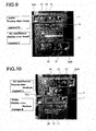
FIG. 9 ] An explanatory view showing image ranges of the contents in a different way from the case ofFIGS. 1 to 6C . - [
FIG. 10 ] An explanatory view showing image ranges of the contents in a different way from the case ofFIGS. 1 to 6C . - [
FIG. 11 ] An explanatory view showing another embodiment of the in-car operation display device according to the present invention. - [
FIG. 12 ] A control-circuit block diagram of the in-car operation device shown inFIG. 11 . - [
FIG. 13A ] An explanatory view showing a display example of content when a first switch plate of the in-car operation device shown inFIG. 11 is positioned at the upper end portion of the touch display. - [
FIG. 13B ] An explanatory view showing a display example of contents when the first switch plate of the in-car operation device shown inFIG. 11 is positioned at the up-down-directional intermediate portion of the touch display. - [
FIG. 13C ] An explanatory view showing a display example of contents when the first switch plate of the in-car operation device shown inFIG. 11 is positioned at the lower end portion of the touch display. - Hereinafter, embodiments of an in-car operation display device according to the present invention will be explained referring to the drawings.
-
FIG. 1 is a view showing acenter cluster 1 to which the in-car operation display device according to the present invention is provided. Moreover,FIG. 2 is an explanatory enlarged view of asloping portion 1a of thecenter cluster 1 as viewed from an upper-left side ofFIG. 1 . The slopingportion 1a extends in a car-width direction and also in an up-down direction of thecenter cluster 1 ofFIG. 1 . With respect to the car-width direction, this slopingportion 1a is arranged on a center portion of a car-interior rear surface (not shown) of an instrument panel (not shown). - The
center cluster 1 includes anupper attachment portion 1b and alower attachment portion 1c. Theupper attachment portion 1b is continuous with an upper end of the slopingportion 1a, and extends in a frontward direction. Moreover, theupper attachment portion 1b is provided in a connected row arrangement with an upper portion of the car-width-directional center portion of the instrument panel (not shown). Thelower attachment portion 1c is continuous with a lower end of the slopingportion 1a, and extends in a rearward direction. Thislower attachment portion 1c is provided in a connected row arrangement with a center console (not shown). - The
center cluster 1 further includes a lower cluster panel (lower cluster member) 2 and an upper cluster panel (upper cluster member) 3. Thelower cluster panel 2 and theupper cluster panel 3 are coupled and fixed to each other, and are separable from each other. A latching hook, a fixing screw or the like is used as a coupling means for coupling and fixing theselower cluster panel 2 andupper cluster panel 3 to each other. - As shown in
FIGS. 2A and2B , thelower cluster panel 2 includes a left-side wall 2L and a right-side wall 2R. The left-side wall 2L includes a left-guide-side wall portion 2GL at a location corresponding to the slopingportion 1a. The left-guide-side wall portion 2GL has a multilevel portion (multilevel concave). The right-side wall 2R includes a right-guide-side wall portion 2GR at a location corresponding to the slopingportion 1a. The right-guide-side wall portion 2GR has a multilevel portion (multilevel concave). - Moreover, as shown in
FIGS. 2A and2B , aleft sensor substrate 4L is fixed to thelower cluster panel 2. Thisleft sensor substrate 4L is placed in parallel with the left-guide-side wall portion 2GL such that a space exists between theleft sensor substrate 4L and the left-guide-side wall portion 2GL. In the same manner, aright sensor substrate 4R is fixed to thelower cluster panel 2. Thisright sensor substrate 4R is placed in parallel with the right-guide-side wall portion 2GR such that a space exists between theright sensor substrate 4R and the right-guide-side wall portion 2GR. - As shown in
FIG. 2B , a lower-left sensing section Ls1, a middle-left sensing section Ls2 and an upper-left sensing section Ls3 are mounted on theleft sensor substrate 4L, as position sensors. The lower-left sensing section Ls1, the middle-left sensing section Ls2 and the upper-left sensing section Ls3 are respectively placed at one end portion (lower end portion), a central portion and another end portion (upper end portion) of theleft sensor substrate 4L, along an extending direction of the left-guide-side wall portion 2GL. A lower-right sensing section Rs1, a middle-right sensing section Rs2 and an upper-right sensing section Rs3 are mounted on theright sensor substrate 4R, as position sensors. The lower-right sensing section Rs1, the middle-right sensing section Rs2 and the upper-right sensing section Rs3 are respectively placed at one end portion (lower end portion), a central portion and another end portion (upper end portion) of theright sensor substrate 4R, along an extending direction of the right-guide-side wall portion 2GR. - As each of these position sensors, a known position sensor such as a contact-type sensor, a switch-type sensor, a photoelectric-type sensor and a proximity-switch-type sensor can be used.
- It is noted that a first linear potentiometer may be used as a left position sensor in place of the sensing sections Ls1 to Ls3, and a second linear potentiometer may be used as a right position sensor in place of the sensing sections Rs1 to Rs3. However, the first embodiment exemplifies a case that the sensing sections Ls1 to Ls3 and the sensing sections Rs1 to Rs3 are used.
- As shown in
FIGS. 1 ,2 and 2A , adisplay window 3a is formed in theupper cluster panel 3 at a location corresponding to the slopingportion 1a. Atouch display 5 is attached to theupper cluster panel 3 as a display unit (displaying means) such that adisplay screen 5a of thetouch display 5 is exposed through (i.e., faces) thedisplay window 3a. Thetouch display 5 is constituted by a liquid crystal display instrument whose surface includes a touch panel, and the like. - As shown in
FIGS. 2 and 2A , a left guide slit GsL is formed between the left-guide-side wall portion 2GL of thelower cluster panel 2 and a left-side portion of theupper cluster panel 3. The left guide slit GsL extends in the up-down direction as a guide portion and is located at the slopingportion 1a. As shown inFIGS. 2 and 2A , a right guide slit GsR is formed between the right-guide-side wall portion 2GR of thelower cluster panel 2 and a right-side portion of theupper cluster panel 3. The right guide slit GsR extends in the up-down direction as the guide portion and is located at the slopingportion 1a. - A first switch plate SpL is provided at a left portion of the
touch display 5 as a first switch panel (operating portion) which is also referred to as a left slide-operation plate (left slide-operation panel). In the same manner, a second switch plate SpR is provided at a right portion of thetouch display 5 as a second switch panel (operating portion) which is also referred to as a right slide-operation plate (right slide-operation panel). - In
FIG. 3 , the first switch plate SpL is denoted by "Slide SW(L) plate", and the second switch plate SpR is denoted by "Slide SW(R) plate". - The first and second switch plates SpL, SpR are used as operating portions for changing car-installed functions and images of the car-installed functions displayed on the
display screen 5a. - Each of the first and second switch plates SpL, SpR is formed by a transparent or semitransparent panel made of an insulating resin material.
- As shown in
FIGS. 2 and 2A , the first switch plate SpL includes a left operating-plate portion (left operating-panel portion) 6L and a panel main body (reference sign omitted). The left operating-plate portion 6L is provided as the operating portion, and extends along thedisplay screen 5a such that a tip of the left operating-plate portion 6L reaches a center of thedisplay screen 5a with respect to the car-width direction. The panel main body is formed in a substantially L-shape from aside plate portion 7L which is continuous with (i.e. is provided in a connected row arrangement with) one end portion of the left operating-plate portion 6L. As shown inFIG. 2A , the first switch plate SpL further includes aguide plate portion 8L and acontact plate portion 9L. Theguide plate portion 8L is formed integrally with theside plate portion 7L, and is passed through the left guide slit GsL. Thecontact plate portion 9L is formed integrally with theguide plate portion 8L, and is located between the left-guide-side wall portion 2GL and theleft sensor substrate 4L. - The left operating-
plate portion 6L is formed integrally with a pair of touch-sensor protrusions 10 and 11 (switch protrusions for touch detection) and a touch-sensor protrusion 12 (switch protrusion for touch detection). The pair of touch-sensor protrusions sensor protrusions sensor protrusion 12 is in the form of dial protrusion, and is located between the pair of touch-sensor protrusions FIG. 2C(a), a colored left-pointing mark ML is applied to (printed on) the touch-sensor protrusion 10, and a colored right-pointing mark MR is applied to the touch-sensor protrusion 11. Each of the colored left-pointing mark ML and the colored right-pointing mark MR is in a triangular shape and indicates its operating direction. Moreover, a plurality ofgrooves 12a are formed in a peripheral surface (outer circumferential surface) of the touch-sensor protrusion 12. The plurality ofgrooves 12a extend in a protruding direction of the touch-sensor protrusion 12, and are provided at intervals in a circumferential direction of the touch-sensor protrusion 12. Thereby,touch sensor portions 12b are provided between any adjacent two of the plurality ofgrooves 12a. - As shown in
FIG. 2C(b) , transparent electrodes (terminals) 10a and 11a are respectively provided on base ends of the touch-sensor protrusions transparent pattern wiring 10b is provided in the first switch plate SpL, and extends from thetransparent electrode 10a to thecontact plate portion 9L. In the same manner, atransparent pattern wiring 11b is provided in the first switch plate SpL, and extends from thetransparent electrode 11a to thecontact plate portion 9L. - As shown in
FIG. 2C(b) , a plurality of transparent electrodes (terminals) 12c are provided respectively inside the plurality oftouch sensor portions 12b of the touch-sensor protrusion 12.Transparent pattern wirings 12d are provided in the first switch plate SpL, and respectively extend from the plurality oftransparent electrodes 12c to thecontact plate portion 9L. - The
transparent electrodes sensor protrusions touch sensor portions 12b. That is, in this embodiment, the touch-sensor protrusions transparent electrodes - Click catching mechanisms (not shown) are provided in the
lower cluster panel 2 at locations corresponding to the respective sensing sections Ls1, Ls2 and Ls3. Each of the click catching mechanisms catches or stops the first switch plate SpL by click stop. Each of the click catching mechanisms can be constructed by using a known mechanism such as a concave-and-convex and a plate-spring-and-depression. - As shown in
FIGS. 1 and2A , the second switch plate SpR includes a right operating-plate portion (right operating-panel portion) 6R and a panel main body (reference sign omitted). The right operating-plate portion 6R is provided as the operating portion, and extends along thedisplay screen 5a such that a tip of the right operating-plate portion 6R reaches the center of thedisplay screen 5a with respect to the car-width direction. The panel main body is formed in a substantially L-shape from aside plate portion 7R which is continuous with (i.e. is provided in a connected row arrangement with) one end portion of the right operating-plate portion 6R. As shown inFIG. 2A , the second switch plate SpR further includes aguide plate portion 8R and acontact plate portion 9R. Theguide plate portion 8R is formed integrally with theside plate portion 7R, and is passed through the right guide slit GsR. Thecontact plate portion 9R is formed integrally with theguide plate portion 8R, and is located between the right-guide-side wall portion 2GR and theright sensor substrate 4R. - The right operating-
plate portion 6R includes a pair of touch-sensor protrusions 13 and 14 (switch protrusions for touch detection) in a tip portion of the right operating-plate portion 6R. The pair of touch-sensor protrusions sensor protrusions plate portion 6R is formed integrally with a touch-sensor protrusion 15 (switch protrusion for touch detection). The touch-sensor protrusion 15 is in the form of dial protrusion. As shown inFIG. 2D , a colored up-pointing mark MU is applied to (printed on) the touch-sensor protrusion 13, and a colored down-pointing mark MD is applied to the touch-sensor protrusion 14. Each of the colored up-pointing mark MU and the colored down-pointing mark MD is in a triangular shape and indicates its operating direction. Moreover, a plurality ofgrooves 15a are formed in a peripheral surface (outer circumferential surface) of the touch-sensor protrusion 15. The plurality ofgrooves 15a extend in a protruding direction of the touch-sensor protrusion 15, and are provided at intervals in a circumferential direction of the touch-sensor protrusion 15. Thereby,touch sensor portions 15b are provided between any adjacent two of the plurality ofgrooves 15a. - As shown in
FIG. 2D(b) , transparent electrodes (terminals) 13a and 14a are respectively provided on base ends of the touch-sensor protrusions transparent pattern wiring 13b is provided in the second switch plate SpR, and extends from thetransparent electrode 13a to thecontact plate portion 9R. In the same manner, atransparent pattern wiring 14b is provided in the second switch plate SpR, and extends from thetransparent electrode 14a to thecontact plate portion 9R. - As shown in
FIG. 2D(b) , a plurality of transparent electrodes (terminals) 15c are provided respectively inside the plurality oftouch sensor portions 15b of the touch-sensor protrusion 15.Transparent pattern wirings 15d are provided in the second switch plate SpR, and respectively extend from the plurality oftransparent electrodes 15c to thecontact plate portion 9R. - The transparent electrodes and the transparent pattern wirings are formed by means of pattern printing (printed wiring) before forming the touch-
sensor protrusions touch sensor portions 15b. That is, in this embodiment, the touch-sensor protrusions touch sensor portions 15b can be formed after forming the transparent electrodes and the transparent pattern wirings. - Click catching mechanisms (not shown) are provided in the
lower cluster panel 2 at locations corresponding to the respective sensing sections Rs1, Rs2 and Rs3. Each of the click catching mechanisms catches or stops the second switch plate SpR by click stop. Each of the click catching mechanisms can be constructed by using a known mechanism such as a concave-and-convex and a plate-spring-and-depression. - The transparent pattern wirings 10b, 11b and 12d are connected with flexible wirings (not shown) at the
contact plate portion 9L. Thereby, the transparent pattern wirings 10b, 11b and 12d are connected through the flexible wirings to anarithmetic control circuit 20. Hence, thearithmetic control circuit 20 receives operations of the touch-sensor protrusions contact plate portion 9R. Thereby, the transparent pattern wirings 13b, 14b and 15d are connected through the flexible wirings to thearithmetic control circuit 20. Hence, thearithmetic control circuit 20 receives operations of the touch-sensor protrusions arithmetic control circuit 20 performs a display control of thetouch display 5 and operational controls of anavigation control section 21, an air-conditioner control section 22 and anaudio control section 23. - Next, actions of the in-car operation display device having the above-mentioned configurations will now be explained.
- When electric power is turned on by an accessary switch (ACC, not shown) of the car, the
arithmetic control circuit 20 receives outputs of the respective sensing sections Ls1 to Ls3 which are the position sensors. At the same time, thearithmetic control circuit 20 also receives outputs of the respective sensing sections Rs1 to Rs3 which are the position sensors. Then, thearithmetic control circuit 20 starts to control. - The lower-left sensing section Ls1 which is the position sensor detects the
contact plate portion 9L of the first switch plate SpL when the first switch plate SpL is positioned at a lower end portion of thetouch display 5. Then, the lower-left sensing section Ls1 outputs this detection signal (to the arithmetic control circuit 20). The middle-left sensing section Ls2 which is the position sensor detects thecontact plate portion 9L of the first switch plate SpL when the first switch plate SpL is positioned at a central portion of thetouch display 5 with respect to the up-down direction. Then, the middle-left sensing section Ls2 outputs this detection signal (to the arithmetic control circuit 20). Moreover, the upper-left sensing section Ls3 which is the position sensor detects thecontact plate portion 9L of the first switch plate SpL when the first switch plate SpL is positioned at an upper end portion of thetouch display 5. Then, the upper-left sensing section Ls3 outputs this detection signal (to the arithmetic control circuit 20). - Similarly, the lower-right sensing section Rs1 which is the position sensor detects the
contact plate portion 9R of the second switch plate SpR when the second switch plate SpR is positioned at the lower end portion of thetouch display 5. Then, the lower-right sensing section Rs1 outputs this detection signal (to the arithmetic control circuit 20). The middle-right sensing section Rs2 which is the position sensor detects thecontact plate portion 9R of the second switch plate SpR when the second switch plate SpR is positioned at the central portion of thetouch display 5 with respect to the up-down direction. Then, the middle-right sensing section Rs2 outputs this detection signal (to the arithmetic control circuit 20). Moreover, the upper-right sensing section Rs3 which is the position sensor detects thecontact plate portion 9R of the second switch plate SpR when the second switch plate SpR is positioned at the upper end portion of thetouch display 5. Then, the upper-right sensing section Rs3 outputs this detection signal (to the arithmetic control circuit 20). - In such a way, the detection signals derived from the respective sensing sections Ls1-Ls3 and Rs1-Rs3 are inputted to the
arithmetic control circuit 20. - In this embodiment, a car-installed function that is operated by the first switch plate SpL is an audiovisual function (audio device). An image for operating the audio device is shown on the
touch display 5. In relation to this image, by operating the touch-sensor protrusions touch sensor portions 12b of the touch-sensor protrusion 12, a volume level of sound can be increased or decreased. A driver can find (recognize) the touch-sensor protrusions sensor protrusions sensor protrusions - Moreover, in this embodiment, a car-installed function that is operated by the second switch plate SpR is an air-conditioning function (air conditioner). An image for operating the air conditioner is shown on the
touch display 5. In relation to this image, by operating the touch-sensor protrusions touch sensor portions 15b of the touch-sensor protrusion 15, rotational speed of a blast fan can be increased or decreased so that a strength of air blow can be adjusted. A driver can find (recognize) the touch-sensor protrusions sensor protrusions sensor protrusions - In this embodiment, the car-installed function that is operated by the first switch plate SpL is the audiovisual function (audio device), while the car-installed function that is operated by the second switch plate SpR is the air-conditioning function (air conditioner). However, the car-installed functions which are operated by the first switch plate SpL and the second switch plate SpR may be the other functions (the other devices).
- On the basis of the above-mentioned detection signals, the
arithmetic control circuit 20 determines a position of the first switch plate SpL by selecting from the lower end portion, the up-down-directional central portion and the upper end portion of thetouch display 5. In the same manner, thearithmetic control circuit 20 determines a position of the second switch plate SpR by selecting from the lower end portion, the up-down-directional central portion and the upper end portion of thetouch display 5. Moreover, on the basis of these detection signals, thearithmetic control circuit 20 starts a control action as shown by a flowchart ofFIG. 4 . - In the case that the first switch plate SpL exists at an up-down-directional intermediate portion of the
touch display 5 as shown inFIG. 5 , the first switch plate SpL can slide in the upper direction and also in the downward direction as shown by arrows A2 and A3. In the case that the second switch plate SpR exists at the lower end portion of thetouch display 5 as shown inFIG. 5 , the second switch plate SpR can slide in the upper direction shown by an arrow A4. - When electric power is turned on by the accessary switch (ACC) of the car, the
arithmetic control circuit 20 judges whether or not at least one of the first switch plate SpL and the second switch plate SpR (slide switch SW(L or R)) is positioned at the upper end of thetouch display 5, at step S1. If any of the first switch plate SpL and the second switch plate SpR is not positioned at the upper end of thetouch display 5, the program proceeds to step S2. If at least one of the first switch plate SpL and the second switch plate SpR is positioned at the upper end of thetouch display 5, the program proceeds to step S5. - At step S2, the
arithmetic control circuit 20 judges whether or not both of the first switch plate SpL and the second switch plate SpR are positioned at the lower end of thetouch display 5. If both of the first switch plate SpL and the second switch plate SpR are positioned at the lower end of thetouch display 5, the program proceeds to step S 2-1. If at least one of the first switch plate SpL and the second switch plate SpR is not positioned at the lower end of thetouch display 5, the program proceeds to step S3. - In the case that the program proceeds from step S2 to step S2-1, both of the first switch plate SpL and the second switch plate SpR exist at the lower end of the
touch display 5. In this case, the tip (right end) of the left operating-plate portion 6L of the first switch plate SpL faces the tip (left end) of the right operating-plate portion 6R of the second switch plate SpR to have a minute space between the tip of the left operating-plate portion 6L and the tip of the right operating-plate portion 6R. - At step S2-1, the
arithmetic control circuit 20 calls up (or retrieves) image information from thenavigation control section 21. From this image information, thearithmetic control circuit 20 obtains a navigation image as shown inFIG. 6A(b) , and displays this navigation image (image size: large) as a content A ofFIG. 6A(a) . That is, the navigation image is displayed over a range from upper ends of the first and second switch plates SpL and SpR (slide switches SW(L and R)) to the upper end of thetouch display 5. - At the same time, the
arithmetic control circuit 20 calls up (or retrieves) audio-control information which is used for controlling the audio device, from theaudio control section 23. From this audio-control information, thearithmetic control circuit 20 obtains an audio-device-operation image for operating the audio device as show inFIG. 6A(b) , and displays this audio-device-operation image (image size: minimum) as a content B ofFIG. 6A(a) . That is, the audio-device-operation image is displayed over a range from the lower end of thetouch display 5 to the upper end of the first switch plate SpL (slide switch SW(L)). - Moreover, the
arithmetic control circuit 20 calls up (or retrieves) air-conditioner information which is used for controlling the air conditioner, from the air-conditioner control section 22. From this air-conditioner information, thearithmetic control circuit 20 obtains an air-conditioner-operation image for operating the air conditioner as show inFIG. 6A(b) , and displays this air-conditioner-operation image (image size: minimum) as a content C ofFIG. 6A(a ). That is, the air-conditioner-operation image is displayed over a range from the lower end of thetouch display 5 to the upper end of the second switch plate SpR (slide switch SW(R)). - Accordingly, the minimum contents B and C are displayed respectively in left and right portions of the lower end portion of the
touch display 5 such that the content B and the content C are arranged side by side in a line with respect to the right-left direction. On the other hand, the content A having a large size is displayed above the contents B and C. - In this example, the first switch plate SpL which is provided for operating the content B is located on, i.e., overlaps with (the image of) the content B, and the second switch plate SpR which is provided for operating the content C is located on, i.e., overlaps with (the image of) the content C. By touching (touch-operating) a menu bar, operational buttons and the like of the content A which appear on the
touch display 5, a change control for displayed view and the like of the content A are conducted. - As mentioned above, the minimum contents B and C are displayed respectively in left and right portions of in the lower end portion of the
touch display 5 such that the content B and the content C are arranged side by side. However, the driver can operate the touch-sensor protrusions sensor protrusions sensor protrusions touch sensor portions 12b of the touch-sensor protrusion 12. - In the same manner, the driver can operate the touch-
sensor protrusions sensor protrusions sensor protrusions touch sensor portions 15b of the touch-sensor protrusion 15. - A detailed explanation about operations of the first switch plate SpL and the second switch plate SpR will be omitted.
- At step S3, the
arithmetic control circuit 20 judges whether or not the first switch plate SpL (slide switch SW(L)) is positioned above (i.e. takes an upper position relative to) the second switch plate SpR (slide switch SW(R)). - If the first switch plate SpL is positioned at the up-down-directional central portion of the
touch display 5, the program proceeds to step S3-1. - On the other hand, if the first switch plate SpL is not positioned at the up-down-directional central portion of the
touch display 5, the program proceeds to step S4. - At step S3-1, the
arithmetic control circuit 20 calls up (retrieves) image information from thenavigation control section 21. From this image information, thearithmetic control circuit 20 obtains a navigation image as exemplified inFIG. 6A(b) , and displays this navigation image as the content A over a range from the upper end of the first switch plate SpL to the upper end of thetouch display 5. - At the same time, the
arithmetic control circuit 20 calls up (retrieves) audio-control information which is used for controlling the audio device, from theaudio control section 23. From this audio-control information, thearithmetic control circuit 20 obtains an audio-device-operation image for operating the audio device as exemplified inFIG. 6A(b) , and displays this audio-device-operation image as the content B ofFIG. 6B . That is, the audio-device-operation image is displayed over a range from the upper end of the first switch plate SpL (slide switch SW(L)) to the upper end of the second switch plate SpR (slide switch SW(R)). - Moreover, the
arithmetic control circuit 20 calls up (retrieves) air-conditioner information which is used for operating the air conditioner, from the air-conditioner control section 22. From this air-conditioner information, thearithmetic control circuit 20 obtains an air-conditioner-operation image for operating the air conditioner as exemplified inFIG. 6A(b) , and displays this air-conditioner-operation image as the content C ofFIG. 6B . That is, the air-conditioner-operation image is displayed over a range from the upper end of the second switch plate SpR (slide switch SW(R)) to the lower end of thetouch display 5 as shown inFIG. 6B . - Accordingly, the contents A and B each having a medium size and the content C having a small size are displayed sequentially from above, on the
touch display 5. In this pattern, the contents A and B are easy to recognize. - At step S4, the
arithmetic control circuit 20 calls up (retrieves) image information from thenavigation control section 21. From this image information, thearithmetic control circuit 20 obtains a navigation image as exemplified inFIG. 6A(b) , and displays this navigation image as the content A ofFIG. 6C . That is, the navigation image is displayed over a range from the upper end of the second switch plate SpR (slide switch SW(R)) to the upper end of thetouch display 5. - At the same time, the
arithmetic control circuit 20 calls up (retrieves) air-conditioner information which is used for operating the air conditioner, from the air-conditioner control section 22. From this air-conditioner information, thearithmetic control circuit 20 obtains an air-conditioner-operation image for operating the air conditioner as exemplified inFIG. 6A(b) , and displays this air-conditioner-operation image as the content C ofFIG. 6C . That is, the air-conditioner-operation image is displayed over a range from the upper end of the first switch plate SpL (slide switch SW(L)) to the upper end of the second switch plate SpR (slide switch SW(R)) as shown inFIG. 6C . - Moreover, the
arithmetic control circuit 20 calls up (or retrieves) audio-control information which is used for controlling the audio device, from theaudio control section 23. From this audio-control information, thearithmetic control circuit 20 obtains an audio-device-operation image for operating the audio device as exemplified inFIG. 6A(b ), and displays this audio-device-operation image as the content B ofFIG. 6C . That is, the audio-device-operation image is displayed over a range from the upper end of the first switch plate SpL (slide switch SW(L)) to the lower end of thetouch display 5, as shown inFIG. 6C . - Accordingly, the contents A and C each having the medium size and the content B having the small size are displayed sequentially from above, on the
touch display 5. In this pattern, the contents A and C are easy to recognize. - The following image-display controls are performed after step S5 although displayed patterns of the contents A to C are omitted in the drawings.
- At step S5, the
arithmetic control circuit 20 judges whether or not both of the first switch plate SpL (slide switch SW(L)) and the second switch plate SpR (slide switch SW(R)) are positioned at the upper end of thetouch display 5. - If it is determined that both of the first switch plate SpL and the second switch plate SpR are positioned at the upper end of the
touch display 5, the program proceeds to step S5-1. If it is determined that at least one of the first switch plate SpL and the second switch plate SpR is not positioned at the upper end of thetouch display 5, the program proceeds to step S6. - At step S5-1, the
arithmetic control circuit 20 calls up (retrieves) image information from thenavigation control section 21. From this image information, thearithmetic control circuit 20 obtains a navigation image as exemplified inFIG. 6A(b) , and displays this navigation image (image size: maximum) as the content A. That is, the navigation image is displayed over a range from lower ends of the first and second switch plates SpL and SpR (slide switches SW(L and R)) to the lower end of thetouch display 5. - At the same time, the
arithmetic control circuit 20 calls up (or retrieves) audio-control information which is used for controlling the audio device, from theaudio control section 23. From this audio-control information, thearithmetic control circuit 20 obtains an audio-device-operation image for operating the audio device as exemplified inFIG. 6A(b) , and displays this audio-device-operation image (image size: minimum) as the content B. That is, the audio-device-operation image is displayed over a range from the upper end of thetouch display 5 to the lower end of the first switch plate SpL. - Moreover, the
arithmetic control circuit 20 calls up (or retrieves) air-conditioner information which is used for operating the air conditioner, from the air-conditioner control section 22. From this air-conditioner information, thearithmetic control circuit 20 obtains an air-conditioner-operation image for operating the air conditioner as exemplified inFIG. 6A(b) , and displays this air-conditioner-operation image (image size: minimum) as the content C. That is, the air-conditioner-operation image is displayed over a range from the upper end of thetouch display 5 to the lower end of the second switch plate SpR. - Accordingly, the minimum contents B and C are displayed respectively in left and right portions of the upper end portion of the
touch display 5 such that the content B and the content C are arranged side by side in a line with respect to the right-left direction. On the other hand, the content A having a large size is displayed below the contents B and C. In this pattern, the content A is easy to recognize. By operating a menu bar, operational buttons and the like of the content A which appear on the screen of thetouch display 5, a view control of the content A is conducted to control the function of the content A. - At step S6, the
arithmetic control circuit 20 judges whether or not the first switch plate SpL (slide switch SW(L)) is positioned at the upper end portion of thetouch display 5. - If the first switch plate SpL is positioned at the upper end portion of the
touch display 5, the program proceeds to step S6-1. - On the other hand, if the first switch plate SpL is not positioned at the upper end portion of the
touch display 5, the program proceeds to step S7. - In the case that the program proceeds from step S6 to step S6-1, the first switch plate SpL exists at the upper end portion of the
touch display 5 whereas the second switch plate SpR does not exist at the upper end portion of thetouch display 5. - At step S6-1, the
arithmetic control circuit 20 calls up (retrieves) audio-control information which is used for controlling the audio device, from theaudio control section 23. From this audio-control information, thearithmetic control circuit 20 obtains an audio-device-operation image for operating the audio device as exemplified inFIG. 6A(b) . Then, thearithmetic control circuit 20 displays this audio-device-operation image as the content B over a range from the upper end of thetouch display 5 to the upper end of the second switch plate SpR. - At the same time, the
arithmetic control circuit 20 calls up (retrieves) air-conditioner information which is used for operating the air conditioner, from the air-conditioner control section 22. From this air-conditioner information, thearithmetic control circuit 20 obtains an air-conditioner-operation image for operating the air conditioner as exemplified inFIG. 6A(b) . Then, thearithmetic control circuit 20 displays this air-conditioner-operation image as the content C over a range from the upper end of the second switch plate SpR to the lower end of thetouch display 5. - Accordingly, the contents B and C each having a medium size are displayed sequentially from above, on the
touch display 5. In this pattern, the contents B and C are easy to recognize. - In the case that the program proceeds from step S6 to step S7, the first switch plate SpL does not exist at the upper end portion of the
touch display 5 whereas the second switch plate SpR exists at the upper end portion of thetouch display 5. - At step S7, the
arithmetic control circuit 20 calls up (retrieves) air-conditioner information which is used for operating the air conditioner, from the air-conditioner control section 22. From this air-conditioner information, thearithmetic control circuit 20 obtains an air-conditioner-operation image for operating the air conditioner as exemplified inFIG. 6A(b) . Then, thearithmetic control circuit 20 displays this air-conditioner-operation image as the content C over a range from the upper end of the first switch plate SpL to the upper end of thetouch display 5. - At the same time, the
arithmetic control circuit 20 calls up (retrieves) audio-control information which is used for controlling the audio device, from theaudio control section 23. From this audio-control information, thearithmetic control circuit 20 obtains an audio-device-operation image for operating the audio device as exemplified inFIG. 6A(b) . Then, thearithmetic control circuit 20 displays this audio-device-operation image as the content B over a range from the upper end of the first switch plate SpL to the lower end of thetouch display 5. - Accordingly, the contents C and B each having a medium size are displayed sequentially in this order from above, on the
touch display 5. In this pattern, the contents B and C are easy to recognize. - In the above-explained embodiment, the sensing sections Ls1 to Ls3 are provided for sensing the position of the first switch plate SpL with respect to the up-down direction. Similarly, the sensing sections Rs1 to Rs3 are provided for sensing the position of the second switch plate SpR with respect to the up-down direction. However, the configuration according to the present invention is not necessarily limited to this. For example, the up-down-directional position of the first switch plate SpL and/or the second switch plate SpR can be continuously sensed by a linear position sensor such as the above-mentioned linear potentiometer and a linear scale.
- Views as shown in
FIGS. 6D to 6F may be adopted when at least one of the first switch plate SpL and the second switch plate SpR is positioned at the upper end portion of thetouch display 5. - That is, as shown in
FIG. 6D , when both of the first switch plate SpL and the second switch plate SpR are positioned at the upper end portion of thetouch display 5; the content B is displayed over a range from the lower end of the first switch plate SpL to the upper end of thetouch display 5, and the content C is displayed over a range from the lower end of the second switch plate SpR to the upper end of thetouch display 5. In this case, no image may be displayed over a range from the lower ends of the first and second switch plates SpL, SpR to the lower end of thetouch display 5. Alternatively, the above-mentioned content A may be displayed over the range from the lower ends of the first and second switch plates SpL, SpR to the lower end of thetouch display 5. - Moreover, as shown in
FIG. 6E , when the second switch plate SpR has been moved to the up-down-directional intermediate portion of thetouch display 5 under a state where the first switch plate SpL exists at the upper end portion of thetouch display 5; the content B is displayed over a range from the upper end of the second switch plate SpR to the upper end of thetouch display 5, and the content C is displayed over a range from the lower end of the second switch plate SpR to the lower end of thetouch display 5. - Moreover, as shown in
FIG. 6F , when the first switch plate SpL has been moved to the up-down-directional intermediate portion of thetouch display 5 under a state where the second switch plate SpR exists at the upper end portion of thetouch display 5; the content C is displayed over a range from the upper end of the first switch plate SpL to the upper end of thetouch display 5, and the content B is displayed over a range from the lower end of the first switch plate SpL to the lower end of thetouch display 5. - Views as shown in
FIGS. 7(a) and 7(b) may be adopted, in the case that one of the first switch plate SpL and the second switch plate SpR is positioned at the upper end portion of thetouch display 5 and another of the first switch plate SpL and the second switch plate SpR is positioned at the lower end portion of thetouch display 5. - That is, in the case that the first switch plate SpL is positioned at the upper end portion of the
touch display 5 and the second switch plate SpR is positioned at the lower end portion of thetouch display 5 as shown inFIG. 7(a) , the content B can be displayed on an upper portion of thetouch display 5 so that the content C is displayed on a lower portion of thetouch display 5. - Moreover, in the case that the second switch plate SpR is positioned at the upper end portion of the
touch display 5 and the first switch plate SpL is positioned at the lower end portion of thetouch display 5 as shown inFIG. 7(b) , the content C can be displayed on an upper portion of thetouch display 5 so that the content B is displayed on a lower portion of thetouch display 5. - Also in this example, the first switch plate SpL for operating the content B is located on, i.e., overlaps with (the image of) the content B whereas the second switch plate SpR for operating the content C is located on, i.e., overlaps with (the image of) the content C.
- In this example, the position of each of the first switch plate SpL and the second switch plate SpR with respect to the up-down direction is continuously sensed by a potentiometer, a linear scale or the like. As shown in
FIG. 8A , thearithmetic control circuit 20 displays the image of the content A over a range from the upper end of the first switch plate SpL to the upper end of thetouch display 5, displays the image of the content B over a range from the upper end of the first switch plate SpL to the upper end of the second switch plate SpR, and displays the image of the content C over a range from the upper end of the second switch plate SpR to the lower end of thetouch display 5. - Under this situation, the first switch plate SpL is operatively moved in the upper direction as shown by an arrow A5. At this time, by sensing the up-down-directional position of the first switch plate SpL, the
arithmetic control circuit 20 gradually reduces the image of the content A and gradually enlarges the image of the content B as shown inFIGS. 8B and8C . Then, when the first switch plate SpL reaches the upper end of thetouch display 5 as shown inFIG. 8D , thearithmetic control circuit 20 removes (i.e. does not display) the image of the content A and maximizes the image of the content B. - As shown in
FIG. 9 , when the first switch plate SpL is positioned at the upper end portion of thetouch display 5 and the second switch plate SpR is positioned at the lower end portion of thetouch display 5, the audio-device-operation image of the content B can be displayed over a range from the upper end of the second switch plate SpR to the upper end of thetouch display 5 so that the air-conditioner-operation image of the content C is displayed over a range from the upper end of the second switch plate SpR to the lower end of thetouch display 5. - Moreover, as shown in
FIG. 10 , when the first switch plate SpL is positioned at the up-down-directional central portion of thetouch display 5 and the second switch plate SpR is positioned at the upper end portion of thetouch display 5, the air-conditioner-operation image of the content C can be displayed over a range from the upper end of the first switch plate SpL to the upper end of thetouch display 5 so that the audio-device-operation image of the content B is displayed over a range from the upper end of the first switch plate SpL to the lower end of thetouch display 5. - In the above-explained first embodiment, the first switch plate SpL and the second switch plate SpR are respectively provided at both sides of the
touch display 5. However, the configuration according to the present invention is not necessarily limited to this. - For example, as shown in
FIG. 11 , only the first switch plate SpL may be provided by omitting the second switch plate SpR of the first embodiment. In such a case, the left operating-plate portion 6L of the first switch plate SpL may be set to have a length equal to an entire width of thetouch display 5 with respect to the right-left direction. In this case, the touch-sensor protrusions plate portion 6L of the first switch plate SpL in addition to the touch-sensor protrusions plate portion 6L. - In this embodiment, the
arithmetic control circuit 20 shown inFIG. 12 receives touch-operation signals derived from the touch-sensor protrusions arithmetic control circuit 20. - The
arithmetic control circuit 20 carries out the display control of thetouch display 5 for the respective contents on the basis of the detected position signals, and controls or actuates thenavigation control section 21, the air-conditioner control section 22 and theaudio control section 23. Moreover, thearithmetic control circuit 20 carries out the operational controls and the display controls for the functions of car-installed devices corresponding to the contents of thetouch display 5, on the basis of the touch-operation signals derived from the touch-sensor protrusions - For example, the
arithmetic control circuit 20 displays the content B over an entire range of thetouch display 5 when the first switch plate SpL is positioned at the upper end of thetouch display 5 as shown inFIG. 13A . - Moreover, when the first switch plate SpL is positioned at the up-down-directional intermediate portion of the
touch display 5 as shown inFIG. 13B , thearithmetic control circuit 20 displays the content A over a range from the upper end of the first switch plate SpL to the upper end of thetouch display 5 and displays the content B over a range from the upper end of the first switch plate SpL to the lower end of thetouch display 5. - Furthermore, when the first switch plate SpL is positioned at the lower end of the
touch display 5 as shown inFIG. 13C , thearithmetic control circuit 20 displays the content B over a range from the upper end of the first switch plate SpL to the upper end of thetouch display 5 and displays the content A over a range from the upper end of the first switch plate SpL to the lower end of thetouch display 5. At this time, the content B has a relatively large size whereas the content A has a minimum size. - According to this embodiment, in the case that a plurality of operational buttons are displayed on the
touch display 5 in parallel with each other (i.e., in a side-by-side arrangement) along the right-left direction, the plurality of operational buttons can be selected by operating the touch-sensor protrusions touch display 5 in parallel with each other along the up-down direction, the plurality of operational menus can be selected by operating the touch-sensor protrusions - In this embodiment, for example, the content B is the navigation image, and the content A is the audio-device-operation image or the air-conditioner-operation image.
- In a common switching structure of touch display, operational frames and/or operational buttons each of which indicates its title are merely displayed on a screen of the touch display. In this structure, the operational frames and/or operational buttons of the touch display are operated by touch operations so that a screen view (displayed image) is changed and/or peripheral devices corresponding to the screen view are operated. In such a common touch display, many operational menus can be provided in a limited area and also can be flexibly arranged. However, the driver tends to gaze or watch the screen in order to find a desired operational menu because there is no concave or convex on the screen of the touch display. Hence, it is difficult to operate the touch display while driving the car.
- On the other hand, in the case that an in-car operation display device is constituted by a liquid crystal display instrument or the like and hard switches (hard SW) which are placed around the liquid crystal display instrument and which are used for operating a car-installed device(s), the driver gropes for a desired switch among the hard switches and thereby can find the desired switch in a short time by tactile perception of shapes of the hard switches. By so-doing, the driver can operate the car-installed device. However, in such a case, the hard switches cannot be moved to a location convenient for the driver to use because the hard switches (hard SW) are fixed to predetermined spots. If trying to provide many hard switches at the convenient location, the number of components becomes large.
- Contrary to this, in the embodiment according to the present invention, the first switch plate SpL and the second switch plate SpR (slide switches SW(L and R)) which are transparent are respectively provided on the left and right portions of the
touch display 5 as touch panels. These first switch plate SpL and second switch plate SpR can move (slide) in the upper and lower directions within a view region of thetouch display 5. - Because each of the first switch plate SpL and the second switch plate SpR is formed with the touch-sensor protrusions 10-15 which are concave-convex-shaped switches, the driver can recognize locations of the touch-sensor protrusions 10-15 without visual check (see
FIG. 2 ). Because each of the first switch plate SpL and the second switch plate SpR (slide switches SW(L and R)) is made of a transparent material, the driver can see the displayed contents of thetouch display 5 through the first switch plate SpL or the second switch plate SpR. The contents displayed on thetouch display 5 can be changed by moving the first switch plate SpL and the second switch plate SpR in the upper and lower directions shown by the arrows A2 and A3 (seeFIG. 5 ). - Because the transparent first and second switch plates (slide switches SW(L and R)) are provided, the locations of switches which are displayed on the
touch display 5 can be found by convexoconcave. Therefore, merit of the hard switch (i.e., an ability of operating without visual check) can be added without impairing merit of the touch display 5 (i.e., an ability of freely changing design and image position). Accordingly, the driver can indirectly operate thetouch display 5 even while driving the car. - Moreover, because the first and second switch plates (slide switches SW(L and R)) are movable, the driver can move each of the first and second switch plates (slide switches SW(L and R)) to a desired position of the driver. By the movement of this switch plate (slide switch SW), the view of the
touch display 5 is varied so that display areas (image ranges) of the respective contents expand or contract to follow the movement. Therefore, functions of a content which is desired to be used by the driver and its display area are expanded whereas functions of a content which is not desired to be used and its display area are minimized. Thereby, a screening (separation) among much information becomes easy (seeFIG. 5 ). - In the in-car operation display device according to the first embodiment as shown in
FIGS. 1 and2 , the display areas (image ranges) of the three contents A to C are varied in dependence upon positions of the two slide switches SW(L and R). That is, the display areas are determined according to a positional relation between the slide switch SW(L) and the slide switch SW(R). The content A is always displayed on the upper portion of the display screen unless the slide switch SW(L) or the slide switch SW(R) is brought to an uppermost portion of thedisplay screen 5a. The content B is displayed from the upper end portion of the slide switch SW(L) to the upper end of the slide switch SW(R) or to the lower end (of the display screen) of thetouch display 5. In the same manner as the content B, the content C is displayed from the upper end portion of the slide switch SW(R) to the to the upper end of the slide switch SW(L) or to the lower end of thetouch display 5. It is noted that the other detailed operations which are less frequently used are conducted by directly touching thetouch display 5. - Because the transparent first and second switch plates (slide switches SW(L and R)) are provided, the locations of respective switches which are displayed on the
touch display 5 can be found by convexoconcave. Therefore, merit of the hard switch (i.e., the ability of operating without visual check) can be added without impairing merit of the touch display 5 (i.e., the ability of freely changing design and image position). Accordingly, the driver can easily operate thetouch display 5 even while driving the car. - Moreover, because the slide switches SW(L and R) are movable, the driver can move each of the slide switches SW(L and R) to a position desired by the driver. By the movement of this slide switch SW, the view of the
touch display 5 is varied so that the display areas (image ranges) of the respective contents expand or contract to follow the movement. Therefore, functions of a content which is desired to be used by the driver and its display area are expanded whereas functions of a content which is not desired to be used and its display area are minimized. Thereby, a screening (separation) among much information becomes easy. - In the in-car operation display device according to the second embodiment as shown in
FIG. 10 , a simplification is attained by using only one slide switch SW which covers a horizontal width of the display screen. In the second embodiment, two contents are displayed. The content A is constantly displayed on the upper portion of the display screen, i.e., from the upper end of the display screen to the upper end portion of the slide switch SW. The content B is displayed from the upper end portion of the slide switch SW to the lower end (of the display screen) of thetouch display 5. - Because only one slide switch SW is attached to one side of the
touch display 5, patterns of display changes (image changes) are reduced so that the simplified structure can be attained. - As explained above, the car-state changing-operation device in the embodiments according to the present invention includes: a display unit (touch display 5) including a touch-panel-type display screen (5a) on which an image of a car function is displayed; an operating means (first switch plate SpL, second switch plate SpR) configured to be operated such that a car state is changed based on the image of the car function displayed on the display screen (5a); and a control circuit (arithmetic control circuit 20) configured to perform a display control for the image of the car function, and to control the car function by an operation of the operating means (first switch plate SpL, second switch plate SpR). Moreover, the operating means (first switch plate SpL, second switch plate SpR) includes an operating-plate portion (6L, 6R) configured to be operated to move along the display screen (5a) of the display unit (touch display 5), and the operating-plate portion (6L, 6R) includes a protruding switch portion (touch-sensor protrusions 10-15).
- According to this structure, the protruding switch portion (touch-sensor protrusions 10-15) can be recognized by touching perception without visual check. Moreover, because the operating-plate portion (6L, 6R) is configured to be operated to move along the display screen (5a) so that the position of the switch portion (touch-sensor protrusions 10-15) of the operating-plate portion (6L, 6R) is moved, the operability of the display unit which is used for indications and operations such as settings and instructions of the car-installed functions can be improved.
- In the car-state changing-operation device as described in the embodiments according to the present invention, the operating-plate portion (6L, 6R) is transparent or semitransparent such that the image displayed on the display screen (5a) can be seen through the operating-plate portion (6L, 6R).
- According to this structure, even if the display screen (5a) overlaps with the operating-plate portion (6L, 6R), an image content (display content) of a portion of the display screen (5a) which entirely overlaps with the operating-plate portion (6L, 6R) can be visually recognized through the operating-plate portion (6L, 6R).
- In the car-state changing-operation device as described in the embodiments according to the present invention, the display screen (5a) extends in the up-down direction and also in the right-left direction, and first and second guide portions (left guide slit GsL, right guide slit GsR) are provided on lateral portions of the display screen (5a) and extend in the up-down direction. Moreover, the operating-plate portion (6L, 6R) is included in each of first and second switch plates (SpL, SpR), and the first and second switch plates (SpL, SpR) are respectively attached to the first and second guide portions (left guide slit GsL, right guide slit GsR) along right and left portions of the display screen (5a) such that the first and second switch plates (SpL, SpR) are operated to move in the up-down direction. Moreover, the control circuit (arithmetic control circuit 20) is configured to control the display unit (touch display 5) in accordance with positions of the first and second switch plates (SpL, SpR) such that images of at least three car-installed functions (contents A, B and C) are displayed on the display screen (5a) and have sizes depending on the positions of the first and second switch plates (SpL, SpR).
- According to this structure, the image sizes of the at least three car-installed functions (contents A, B and C) can be varied depending on the movement positions of the first and second switch plates (SpL, SpR) by operating the first and second switch plates (SpL, SpR). Hence, one or more image among the images of the at least three car-installed functions (contents A, B and C) can be displayed more largely than the remaining one(s). Thereby, an operability of necessary image(s) among the images of the car-installed functions (contents A, B and C) by visual recognition can be improved.
-
- 1
- Center cluster
- 5
- Touch display (Display unit)
- 5a
- Display screen
- 6L
- Left operating-plate portion
- 6R
- Right operating-plate portion
- 10
- Touch-sensor protrusion
- 11
- Touch-sensor protrusion
- 12
- Touch-sensor protrusion
- 13
- Touch-sensor protrusion
- 14
- Touch-sensor protrusion
- 15
- Touch-sensor protrusion
- A
- Content
- B
- Content
- C
- Content
- GsL
- Left guide slit (First guide portion)
- GsR
- Right guide slit (Second guide portion)
- SpL
- First switch plate (operating means)
- SpR
- Second switch plate (operating means)
Claims (3)
- An in-car operation display device comprising:a display unit including a touch-panel-type display screen on which an image of a car-installed function is displayed;an operating means configured to be operated such that a car state is varied based on the image of the car-installed function displayed on the display screen; anda control circuit configured to perform a display control for the image of the car-installed function, and to control the car-installed function by an operation of the operating means,wherein the operating means includes an operating-plate portion configured to be operated to move along the display screen of the display unit, andthe operating-plate portion includes a protruding switch portion.
- The in-car operation display device according to Claim 1, wherein
the operating-plate portion is transparent or semitransparent such that the image displayed on the display screen can be seen through the operating-plate portion. - The in-car operation display device according to one of Claims 1 and 2, wherein
the display screen extends in an up-down direction and also in a right-left direction,
first and second guide portions are provided on lateral portions of the display screen and extend in the up-down direction,
the operating-plate portion is included in each of first and second switch plates,
the first and second switch plates are respectively attached to the first and second guide portions along right and left portions of the display screen such that the first and second switch plates are operated to move in the up-down direction, and
the control circuit is configured to control the display unit in accordance with positions of the first and second switch plates such that images of at least three car-installed functions are displayed on the display screen and have sizes depending on the positions of the first and second switch plates.
Applications Claiming Priority (2)
| Application Number | Priority Date | Filing Date | Title |
|---|---|---|---|
| JP2012093590A JP5882117B2 (en) | 2012-04-17 | 2012-04-17 | In-vehicle operation display device |
| PCT/JP2013/061033 WO2013157492A1 (en) | 2012-04-17 | 2013-04-12 | In-car operation display device |
Publications (2)
| Publication Number | Publication Date |
|---|---|
| EP2839995A1 true EP2839995A1 (en) | 2015-02-25 |
| EP2839995A4 EP2839995A4 (en) | 2017-01-11 |
Family
ID=49383449
Family Applications (1)
| Application Number | Title | Priority Date | Filing Date |
|---|---|---|---|
| EP13777802.3A Withdrawn EP2839995A4 (en) | 2012-04-17 | 2013-04-12 | In-car operation display device |
Country Status (5)
| Country | Link |
|---|---|
| US (1) | US9684392B2 (en) |
| EP (1) | EP2839995A4 (en) |
| JP (1) | JP5882117B2 (en) |
| CN (1) | CN104245430B (en) |
| WO (1) | WO2013157492A1 (en) |
Cited By (4)
| Publication number | Priority date | Publication date | Assignee | Title |
|---|---|---|---|---|
| EP3040229A3 (en) * | 2015-01-02 | 2017-04-26 | Hyundai Motor Company | Vehicle including display apparatus |
| EP4039520A3 (en) * | 2021-02-09 | 2022-10-26 | Hyundai Mobis Co., Ltd. | Vehicle display device |
| DE102023206941A1 (en) | 2023-07-21 | 2025-01-23 | Volkswagen Aktiengesellschaft | Device and method for operating at least one function of a vehicle |
| EP4772378A1 (en) * | 2025-01-03 | 2026-07-08 | Hyundai Mobis Co., Ltd. | Display module |
Families Citing this family (22)
| Publication number | Priority date | Publication date | Assignee | Title |
|---|---|---|---|---|
| JP6183306B2 (en) * | 2013-11-21 | 2017-08-23 | 株式会社デンソー | Operating device |
| KR101508509B1 (en) | 2013-12-19 | 2015-04-08 | 현대자동차주식회사 | An input apparatus, method for inputting an command and a vehicle the input apparatus installed on |
| JP6280815B2 (en) * | 2014-05-26 | 2018-02-14 | トヨタ紡織株式会社 | Door glass lifting switch structure |
| DE102014008040A1 (en) * | 2014-05-28 | 2015-12-03 | GM Global Technology Operations LLC (n. d. Gesetzen des Staates Delaware) | Motor vehicle input / output device and method |
| DE102014218493A1 (en) * | 2014-09-16 | 2016-03-17 | Bayerische Motoren Werke Aktiengesellschaft | Display and operating device, in particular for a motor vehicle, operating element and motor vehicle |
| KR101643557B1 (en) * | 2015-01-02 | 2016-07-29 | 현대자동차주식회사 | Vehicle and controlling method thereof |
| KR101640053B1 (en) * | 2015-01-02 | 2016-07-18 | 현대자동차주식회사 | Display device for vehicle and vehicle comprising the same |
| DE112015006440T5 (en) * | 2015-04-13 | 2017-12-28 | Mitsubishi Electric Corporation | Operating tool, input device and electronic device |
| JP6125582B2 (en) * | 2015-08-20 | 2017-05-10 | カルソニックカンセイ株式会社 | In-vehicle operation display device |
| KR101806892B1 (en) | 2016-05-09 | 2018-01-10 | 엘지전자 주식회사 | Control device for a vehhicle |
| KR101657656B1 (en) * | 2016-08-04 | 2016-09-19 | 현대자동차주식회사 | Vehicle comprising display device |
| DE102016214692B4 (en) * | 2016-08-08 | 2018-02-15 | Audi Ag | Method and user interface relating to haptic feedback for a screen |
| CN108146345B (en) * | 2016-12-06 | 2021-03-30 | Lg电子株式会社 | Vehicle control device and vehicle including the same |
| JP6824047B2 (en) * | 2017-01-20 | 2021-02-03 | 株式会社クボタ | Work vehicle |
| JPWO2018146721A1 (en) * | 2017-02-07 | 2019-06-27 | 三菱電機株式会社 | In-vehicle information device |
| WO2018146722A1 (en) * | 2017-02-07 | 2018-08-16 | 三菱電機株式会社 | Vehicle-mounted information device |
| CN107031532A (en) * | 2017-04-07 | 2017-08-11 | 北京中鼎思宏科技有限公司 | Show interactive system, display interaction control method and automobile |
| JP6403921B1 (en) * | 2017-10-11 | 2018-10-10 | 三菱電機株式会社 | Operation input device |
| DE102018111344B4 (en) * | 2018-05-11 | 2023-01-05 | Motherson Innovations Company Limited | Multifunction device and dashboard with such |
| KR102722047B1 (en) * | 2018-12-28 | 2024-10-29 | 삼성디스플레이 주식회사 | Display device for vehicle |
| JP2024022332A (en) * | 2022-08-05 | 2024-02-16 | 株式会社東海理化電機製作所 | Switch device, vehicle switch device |
| KR20260109391A (en) * | 2025-01-03 | 2026-07-10 | 현대모비스 주식회사 | Display module |
Family Cites Families (7)
| Publication number | Priority date | Publication date | Assignee | Title |
|---|---|---|---|---|
| DE4017897C1 (en) * | 1990-06-02 | 1991-11-21 | Mercedes-Benz Aktiengesellschaft, 7000 Stuttgart, De | |
| US9513744B2 (en) * | 1994-08-15 | 2016-12-06 | Apple Inc. | Control systems employing novel physical controls and touch screens |
| SE510949C2 (en) * | 1997-11-25 | 1999-07-12 | Saab Automobile | Control Panel |
| US6897390B2 (en) * | 2001-11-20 | 2005-05-24 | Touchsensor Technologies, Llc | Molded/integrated touch switch/control panel assembly and method for making same |
| JP4725259B2 (en) | 2005-09-09 | 2011-07-13 | マツダ株式会社 | Vehicle information display device |
| DE102010013843A1 (en) * | 2010-04-03 | 2011-10-06 | Volkswagen Ag | Operating device for use in motor car, has movable operating member that is transparent in fiber optics and transparent element, so that indication reproduced on area is recognized via fiber optics and transparent element |
| JP6315456B2 (en) * | 2013-05-21 | 2018-04-25 | カルソニックカンセイ株式会社 | Touch panel vehicle information display device |
-
2012
- 2012-04-17 JP JP2012093590A patent/JP5882117B2/en not_active Expired - Fee Related
-
2013
- 2013-04-12 CN CN201380020469.5A patent/CN104245430B/en not_active Expired - Fee Related
- 2013-04-12 EP EP13777802.3A patent/EP2839995A4/en not_active Withdrawn
- 2013-04-12 WO PCT/JP2013/061033 patent/WO2013157492A1/en not_active Ceased
- 2013-04-12 US US14/394,567 patent/US9684392B2/en not_active Expired - Fee Related
Cited By (5)
| Publication number | Priority date | Publication date | Assignee | Title |
|---|---|---|---|---|
| EP3040229A3 (en) * | 2015-01-02 | 2017-04-26 | Hyundai Motor Company | Vehicle including display apparatus |
| EP4039520A3 (en) * | 2021-02-09 | 2022-10-26 | Hyundai Mobis Co., Ltd. | Vehicle display device |
| US11691514B2 (en) | 2021-02-09 | 2023-07-04 | Hyundai Mobis Co., Ltd. | Vehicle display device |
| DE102023206941A1 (en) | 2023-07-21 | 2025-01-23 | Volkswagen Aktiengesellschaft | Device and method for operating at least one function of a vehicle |
| EP4772378A1 (en) * | 2025-01-03 | 2026-07-08 | Hyundai Mobis Co., Ltd. | Display module |
Also Published As
| Publication number | Publication date |
|---|---|
| JP2013220736A (en) | 2013-10-28 |
| WO2013157492A1 (en) | 2013-10-24 |
| EP2839995A4 (en) | 2017-01-11 |
| US9684392B2 (en) | 2017-06-20 |
| CN104245430A (en) | 2014-12-24 |
| JP5882117B2 (en) | 2016-03-09 |
| US20150084886A1 (en) | 2015-03-26 |
| CN104245430B (en) | 2016-10-12 |
Similar Documents
| Publication | Publication Date | Title |
|---|---|---|
| US9684392B2 (en) | In-car operation display device | |
| JP4758087B2 (en) | Display device | |
| CN104827908B (en) | Information of vehicles display device | |
| EP2726970B1 (en) | Vehicle operation device and vehicle operation method | |
| JP5456899B2 (en) | Vehicle control device | |
| JP2000194502A (en) | Touch operation input device | |
| JP4649933B2 (en) | Vehicle information display device | |
| JP6035828B2 (en) | Display operation device and display system | |
| WO2014119584A1 (en) | Display control device | |
| CN114391131B (en) | Operating device | |
| JP5778904B2 (en) | Touch input device | |
| CN108108042A (en) | Display apparatus and its control method | |
| JP3668834B2 (en) | Vehicle display device | |
| JP2014172413A (en) | Operation support system, operation support method, and computer program | |
| JP4649932B2 (en) | Vehicle information display device | |
| US20100188198A1 (en) | Function display device | |
| JP2016182856A (en) | Operation system | |
| JP6265839B2 (en) | INPUT DISPLAY DEVICE, ELECTRONIC DEVICE, ICON DISPLAY METHOD, AND DISPLAY PROGRAM | |
| JP7574135B2 (en) | Information processing device and program | |
| JP6125582B2 (en) | In-vehicle operation display device | |
| JP2013033343A (en) | Operation device for vehicle | |
| JP2022170504A5 (en) | ||
| JP2019139009A (en) | Method for control display, and display controller and display system using the same | |
| US12050737B2 (en) | Operation device enabling both push and swipe operation | |
| JP2022170505A (en) | Information processing device and program |
Legal Events
| Date | Code | Title | Description |
|---|---|---|---|
| PUAI | Public reference made under article 153(3) epc to a published international application that has entered the european phase |
Free format text: ORIGINAL CODE: 0009012 |
|
| 17P | Request for examination filed |
Effective date: 20141114 |
|
| AK | Designated contracting states |
Kind code of ref document: A1 Designated state(s): AL AT BE BG CH CY CZ DE DK EE ES FI FR GB GR HR HU IE IS IT LI LT LU LV MC MK MT NL NO PL PT RO RS SE SI SK SM TR |
|
| AX | Request for extension of the european patent |
Extension state: BA ME |
|
| DAX | Request for extension of the european patent (deleted) | ||
| RA4 | Supplementary search report drawn up and despatched (corrected) |
Effective date: 20161213 |
|
| RIC1 | Information provided on ipc code assigned before grant |
Ipc: B60R 11/02 20060101ALI20161207BHEP Ipc: B60R 16/02 20060101AFI20161207BHEP |
|
| STAA | Information on the status of an ep patent application or granted ep patent |
Free format text: STATUS: THE APPLICATION HAS BEEN WITHDRAWN |
|
| 18W | Application withdrawn |
Effective date: 20190318 |