EP2839988A1 - Vehicle seat - Google Patents
Vehicle seat Download PDFInfo
- Publication number
- EP2839988A1 EP2839988A1 EP12874584.1A EP12874584A EP2839988A1 EP 2839988 A1 EP2839988 A1 EP 2839988A1 EP 12874584 A EP12874584 A EP 12874584A EP 2839988 A1 EP2839988 A1 EP 2839988A1
- Authority
- EP
- European Patent Office
- Prior art keywords
- seat
- absorption member
- frame
- supported
- fixed
- Prior art date
- Legal status (The legal status is an assumption and is not a legal conclusion. Google has not performed a legal analysis and makes no representation as to the accuracy of the status listed.)
- Granted
Links
- 238000010521 absorption reaction Methods 0.000 claims abstract description 33
- 238000000034 method Methods 0.000 description 4
- 229910000831 Steel Inorganic materials 0.000 description 2
- 239000010959 steel Substances 0.000 description 2
- 238000007796 conventional method Methods 0.000 description 1
- 238000013016 damping Methods 0.000 description 1
- 230000000694 effects Effects 0.000 description 1
- 230000002787 reinforcement Effects 0.000 description 1
- 229920005989 resin Polymers 0.000 description 1
- 239000011347 resin Substances 0.000 description 1
- 230000002889 sympathetic effect Effects 0.000 description 1
- 229920003002 synthetic resin Polymers 0.000 description 1
- 239000000057 synthetic resin Substances 0.000 description 1
Images



Classifications
-
- B—PERFORMING OPERATIONS; TRANSPORTING
- B60—VEHICLES IN GENERAL
- B60N—SEATS SPECIALLY ADAPTED FOR VEHICLES; VEHICLE PASSENGER ACCOMMODATION NOT OTHERWISE PROVIDED FOR
- B60N2/00—Seats specially adapted for vehicles; Arrangement or mounting of seats in vehicles
- B60N2/50—Seat suspension devices
-
- B—PERFORMING OPERATIONS; TRANSPORTING
- B60—VEHICLES IN GENERAL
- B60N—SEATS SPECIALLY ADAPTED FOR VEHICLES; VEHICLE PASSENGER ACCOMMODATION NOT OTHERWISE PROVIDED FOR
- B60N2/00—Seats specially adapted for vehicles; Arrangement or mounting of seats in vehicles
- B60N2/02—Seats specially adapted for vehicles; Arrangement or mounting of seats in vehicles the seat or part thereof being movable, e.g. adjustable
- B60N2/22—Seats specially adapted for vehicles; Arrangement or mounting of seats in vehicles the seat or part thereof being movable, e.g. adjustable the back-rest being adjustable
-
- B—PERFORMING OPERATIONS; TRANSPORTING
- B60—VEHICLES IN GENERAL
- B60N—SEATS SPECIALLY ADAPTED FOR VEHICLES; VEHICLE PASSENGER ACCOMMODATION NOT OTHERWISE PROVIDED FOR
- B60N2/00—Seats specially adapted for vehicles; Arrangement or mounting of seats in vehicles
- B60N2/64—Back-rests or cushions
-
- B—PERFORMING OPERATIONS; TRANSPORTING
- B60—VEHICLES IN GENERAL
- B60N—SEATS SPECIALLY ADAPTED FOR VEHICLES; VEHICLE PASSENGER ACCOMMODATION NOT OTHERWISE PROVIDED FOR
- B60N2/00—Seats specially adapted for vehicles; Arrangement or mounting of seats in vehicles
- B60N2/68—Seat frames
-
- B—PERFORMING OPERATIONS; TRANSPORTING
- B60—VEHICLES IN GENERAL
- B60N—SEATS SPECIALLY ADAPTED FOR VEHICLES; VEHICLE PASSENGER ACCOMMODATION NOT OTHERWISE PROVIDED FOR
- B60N2/00—Seats specially adapted for vehicles; Arrangement or mounting of seats in vehicles
- B60N2/68—Seat frames
- B60N2/682—Joining means
-
- B—PERFORMING OPERATIONS; TRANSPORTING
- B60—VEHICLES IN GENERAL
- B60N—SEATS SPECIALLY ADAPTED FOR VEHICLES; VEHICLE PASSENGER ACCOMMODATION NOT OTHERWISE PROVIDED FOR
- B60N2205/00—General mechanical or structural details
- B60N2205/20—Measures for elimination or compensation of play or backlash
Definitions
- the present invention relates to a vehicle seat.
- Patent Literature 1 discloses a seat including: side panels arranged on the left and right sides of a seating part of the seat; a front member laid between and fixed to front end portions of the side panels; and a rear member laid between rear end portions of the side panels and fixed to only one of the side panels.
- this vehicle seat is configured to prevent vibrations of the vehicle body caused by travel from being transmitted to the seat and thereby avoid sympathetic vibrations of the seat (this phenomenon will be referred to as resonance. The same applies hereinafter).
- a damping effect is achieved by the frameworks such as the side panels, the front member, and the rear member forming the seating part. For this reason, commoditizing of the frameworks of the seating part is not possible.
- a damper is additionally provided to form a free hinge. This makes the weight increased by the weight of the damper, and can be one cause of increase in cost. Also, a cost is required for attachment.
- An object of the present invention is to provide a vehicle seat which enables commoditizing of frameworks of a seating part and also is light in weight and capable of significantly reducing the cost.
- An aspect of the present invention is a vehicle seat including a seat-cushion frame supported on a vehicle body, a fastener fixed to the seat-cushion frame in a lateral direction, an absorption member supported by the fastener inserted in the absorption member, a seat-back frame supported via the absorption member, and a seat back fixed to the seat-back frame.
- the above aspect brings about practical advantages that the frameworks of the seat can be commoditized, that the weight is lighter by the weight of a damper which is not provided, and that it is possible to significantly reduce the cost.
- the absorption member may be supported between an inner tube fixed to the seat-cushion frame via the fastener and an outer tube fixed to the seat-back frame and configured to absorb vibrations in the lateral direction.
- the absorption member absorbs vibrations applied to the seat-cushion frame.
- the comfortability can be enhanced significantly.
- the absorption member may have a spring constant in a longitudinal direction being five times greater than a spring constant of the absorption member in the lateral direction.
- vibrations at frequencies of 15 to 20 Hertz (Hz) which are likely to be transmitted to the occupant can be absorbed.
- the comfortability can be enhanced significantly.
- the absorption member may have a ring shape and be arranged with an axial direction of the absorption member coinciding with the lateral direction.
- the absorption member is simply inserted between the inner tube and the outer tube. Thus, there is no possibility of incorrect mounting.
- the object of providing a vehicle seat which can enables commoditizing of frameworks of a seating part and also is light in weight and capable of significantly reducing the cost is achieved by including: a seat-cushion frame supported on a vehicle body; a fastener fixed to the seat-cushion frame in a lateral direction; an absorption member supported by the fastener inserted in the absorption member; a seat-back frame supported via the absorption member; and a seat back fixed to the seat-back frame.
- a vehicle seat 1 includes a seat cushion 2, a seat back 3, and a head rest 4 as a seat part 8, and support parts 5.
- the seat cushion 2 is supported on an unillustrated vehicle body with publically known means.
- the seat back 3 is supported on a frame 10 of the seat cushion 2 via each support part 5.
- the head rest 4 is supported on the top of the seat back 3.
- the support part 5 includes a seat-back frame 7 made of steal and fixed to the seat back 3, and a special bolt 9 serving as a fastener.
- An upper portion of the seat-back frame 7 is joined to a frame inside the seat back 3 (a dotted line in an upper right area of Fig. 1 ).
- the special bolt 9 is fixed to the seat-cushion frame 10 via a lower side (seat cushion 2 side) of the seat-back frame 7.
- the special bolt 9 penetrates an absorption member 13 inserted in a hole 7a defined by a flange formed on the seat-back frame 7, and is screwed to a nut 11 fixed to the seat-cushion frame 10.
- This screwed special bolt 9 is screwed in the same horizontal direction as the left-right, horizontal direction (lateral direction) in Fig. 3 .
- a reinforcement flange 7b is formed at the periphery of the seat-back frame 7.
- screwing the special bolt 9 and the nut 11 is employed for the fixing, but a different fixing method may instead be employed.
- the seat back 3 has a front surface 3a and side surfaces 3b.
- the frame 10 exposed from the seat cushion 2 and the seat back 3 are linked and supported by the seat-back frame 7 made of steel.
- a buckle 6 of a safety belt is supported on the frame 10 of the seat cushion 2.
- a recessed portion of the seat back 3 on a lower side (around the side surface 3b in Fig. 2 ) is covered with an unillustrated cover made of resin.
- the special bolt 9 includes a hexagonal head portion 9a, a column portion 9b, and a thread portion 9c.
- the column portion 9b has a columnar shape with a diameter D of, for example, 13 millimeters and a height Hb of, for example, 9.5 millimeters.
- the thread portion 9c is screwed to the nut 11 welded to the seat-cushion frame 10.
- the absorption member 13 is interposed between an inner tube 12 and an outer tube 14.
- the inner tube 12 is synthetic resin formed in a ring shape with an inner diameter of, for example, 13.1 millimeters, an outer diameter of, for example, 17.1 millimeters, and a height Ha of, for example, 11 millimeters.
- the outer tube 14 is steel formed in a right shape with an outer diameter of, for example, 30 millimeters, a height Ha of, for example, 11 millimeters, and a thickness of, for example, 1.6 millimeters.
- the absorption member 13 is arranged with its axial direction coinciding with the axial direction of the special bolt 9 (the left-right, horizontal direction in Fig. 3 ; the lateral direction).
- the absorption member 13 is a rubber product interposed between the inner tube 12 and the outer tube 14.
- the spring constant in the direction perpendicular to the axis is 250, while the spring constant in the axial direction is 50.
- the vehicle seat 1 includes: the frame 10 of the seat cushion 2 supported on the unillustrated vehicle body; the special bolt 9 screwed to the frame 10 of the seat cushion 2 in the horizontal direction; the absorption member 13 supported by the special bolt 9 inserted thereto; the seat-back frame 7 supported via the absorption member 13; and the seat back 3 fixed to the seat-back frame 7.
- the frame 10 of the seat cushion 2 and the seat-back frame 7 of the seat back 3 which are frameworks of the vehicle seat 1 can be commoditized.
- a damper as employed in conventional techniques can be omitted. This makes the weight lighter accordingly, and brings about a practical advantage that the cost can be reduced significantly.
- the absorption member 13 is fixed between the inner tube 12, which is fixed to the frame 10 of the seat cushion 2 via the special bolt 9, and the outer tube 14 fixed to the seat-back frame 7 of the seat back 3. In this way, the absorption member 13 absorbs vibrations applied to the frame 10 of the seat cushion 2. Thus, the comfortability can be improved significantly.
- A illustrates the relationship between frequencies and vibrations in the vehicle seat 1 according to the one embodiment of the present invention
- B illustrates the relationship between frequencies and vibrations in a related technique.
- the spring constant of the absorption member 13 in the direction perpendicular to the axis (longitudinal direction) is 250--a spring constant approximately five times greater than the spring constant in the axial direction (lateral direction) which is 50.
- vibrations at frequencies from 15 to 20 Hz which are likely to be transmitted to the occupant can be absorbed. Accordingly, the comfortability can be improved significantly.
- the vehicle seat is described by taking a seat for an automobile as an example.
- the present invention is not limited to this example and may be a seat mounted on an aircraft, a train, a ship, or the like.
Landscapes
- Engineering & Computer Science (AREA)
- Aviation & Aerospace Engineering (AREA)
- Transportation (AREA)
- Mechanical Engineering (AREA)
- Seats For Vehicles (AREA)
Abstract
Description
- The present invention relates to a vehicle seat.
- As a related vehicle seat, Patent Literature 1 discloses a seat including: side panels arranged on the left and right sides of a seating part of the seat; a front member laid between and fixed to front end portions of the side panels; and a rear member laid between rear end portions of the side panels and fixed to only one of the side panels. Without increasing in weight, this vehicle seat is configured to prevent vibrations of the vehicle body caused by travel from being transmitted to the seat and thereby avoid sympathetic vibrations of the seat (this phenomenon will be referred to as resonance. The same applies hereinafter).
- PTL 1: Japanese Unexamined Patent Application Publication No.
2010-221876 - Here, in such a related technique, a damping effect is achieved by the frameworks such as the side panels, the front member, and the rear member forming the seating part. For this reason, commoditizing of the frameworks of the seating part is not possible. Moreover, a damper is additionally provided to form a free hinge. This makes the weight increased by the weight of the damper, and can be one cause of increase in cost. Also, a cost is required for attachment.
- An object of the present invention is to provide a vehicle seat which enables commoditizing of frameworks of a seating part and also is light in weight and capable of significantly reducing the cost.
- An aspect of the present invention is a vehicle seat including a seat-cushion frame supported on a vehicle body, a fastener fixed to the seat-cushion frame in a lateral direction, an absorption member supported by the fastener inserted in the absorption member, a seat-back frame supported via the absorption member, and a seat back fixed to the seat-back frame.
- The above aspect brings about practical advantages that the frameworks of the seat can be commoditized, that the weight is lighter by the weight of a damper which is not provided, and that it is possible to significantly reduce the cost.
- The absorption member may be supported between an inner tube fixed to the seat-cushion frame via the fastener and an outer tube fixed to the seat-back frame and configured to absorb vibrations in the lateral direction.
- According to the above aspect, the absorption member absorbs vibrations applied to the seat-cushion frame. Thus, the comfortability can be enhanced significantly.
- The absorption member may have a spring constant in a longitudinal direction being five times greater than a spring constant of the absorption member in the lateral direction.
- According to the above configuration, vibrations at frequencies of 15 to 20 Hertz (Hz) which are likely to be transmitted to the occupant can be absorbed. Thus, the comfortability can be enhanced significantly.
- The absorption member may have a ring shape and be arranged with an axial direction of the absorption member coinciding with the lateral direction.
- According to the above configuration, the absorption member is simply inserted between the inner tube and the outer tube. Thus, there is no possibility of incorrect mounting.
-
-
Fig. 1 is a perspective, three-quarter view illustrating a vehicle seat according to one embodiment of the present invention. -
Fig. 2 is an enlarged perspective view of a part II inFig. 1 . -
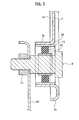
Fig. 3 is an enlarged cross-sectional view taken along a line III-III inFig. 2 . -
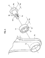
Fig. 4 is an exploded perspective view ofFig. 3 . -
Fig. 5 is data on vibrations of the vehicle seat according to the one embodiment of the present invention relative at given frequencies, illustrated in comparison with a related technique. - The object of providing a vehicle seat which can enables commoditizing of frameworks of a seating part and also is light in weight and capable of significantly reducing the cost is achieved by including: a seat-cushion frame supported on a vehicle body; a fastener fixed to the seat-cushion frame in a lateral direction; an absorption member supported by the fastener inserted in the absorption member; a seat-back frame supported via the absorption member; and a seat back fixed to the seat-back frame.
- Hereinbelow, one embodiment of the present invention will be described with reference to
Figs. 1 to 4 . As illustrated inFig. 1 , a vehicle seat 1 includes aseat cushion 2, aseat back 3, and ahead rest 4 as aseat part 8, and supportparts 5. Theseat cushion 2 is supported on an unillustrated vehicle body with publically known means. Theseat back 3 is supported on aframe 10 of theseat cushion 2 via eachsupport part 5. Thehead rest 4 is supported on the top of theseat back 3. - The
support part 5 includes a seat-back frame 7 made of steal and fixed to theseat back 3, and aspecial bolt 9 serving as a fastener. An upper portion of the seat-back frame 7 is joined to a frame inside the seat back 3 (a dotted line in an upper right area ofFig. 1 ). Thespecial bolt 9 is fixed to the seat-cushion frame 10 via a lower side (seat cushion 2 side) of the seat-back frame 7. - The
special bolt 9 penetrates anabsorption member 13 inserted in ahole 7a defined by a flange formed on the seat-back frame 7, and is screwed to anut 11 fixed to the seat-cushion frame 10. This screwedspecial bolt 9 is screwed in the same horizontal direction as the left-right, horizontal direction (lateral direction) inFig. 3 . Areinforcement flange 7b is formed at the periphery of the seat-back frame 7. In this embodiment, screwing thespecial bolt 9 and thenut 11 is employed for the fixing, but a different fixing method may instead be employed. - The
seat back 3 has afront surface 3a andside surfaces 3b. Theframe 10 exposed from theseat cushion 2 and theseat back 3 are linked and supported by the seat-back frame 7 made of steel. Abuckle 6 of a safety belt is supported on theframe 10 of theseat cushion 2. A recessed portion of theseat back 3 on a lower side (around theside surface 3b inFig. 2 ) is covered with an unillustrated cover made of resin. - Details of the
support part 5, in particular, the structure around thespecial bolt 9 will be described in detail. As illustrated inFig. 4 , thespecial bolt 9 includes ahexagonal head portion 9a, acolumn portion 9b, and athread portion 9c. Thecolumn portion 9b has a columnar shape with a diameter D of, for example, 13 millimeters and a height Hb of, for example, 9.5 millimeters. Thethread portion 9c is screwed to thenut 11 welded to the seat-cushion frame 10. There is astep portion 9d as a step between thecolumn portion 9b and thethread portion 9c. - As illustrated in
Fig. 3 , theabsorption member 13 is interposed between aninner tube 12 and anouter tube 14. Theinner tube 12 is synthetic resin formed in a ring shape with an inner diameter of, for example, 13.1 millimeters, an outer diameter of, for example, 17.1 millimeters, and a height Ha of, for example, 11 millimeters. Theouter tube 14 is steel formed in a right shape with an outer diameter of, for example, 30 millimeters, a height Ha of, for example, 11 millimeters, and a thickness of, for example, 1.6 millimeters. Theabsorption member 13 is arranged with its axial direction coinciding with the axial direction of the special bolt 9 (the left-right, horizontal direction inFig. 3 ; the lateral direction). - The
absorption member 13 is a rubber product interposed between theinner tube 12 and theouter tube 14. The spring constant in the direction perpendicular to the axis is 250, while the spring constant in the axial direction is 50. - Next, the operation of this embodiment will be described.
- The vehicle seat 1 according to this embodiment includes: the
frame 10 of theseat cushion 2 supported on the unillustrated vehicle body; thespecial bolt 9 screwed to theframe 10 of theseat cushion 2 in the horizontal direction; theabsorption member 13 supported by thespecial bolt 9 inserted thereto; the seat-back frame 7 supported via theabsorption member 13; and theseat back 3 fixed to the seat-back frame 7. In this way, theframe 10 of theseat cushion 2 and the seat-back frame 7 of theseat back 3 which are frameworks of the vehicle seat 1 can be commoditized. Thus, a damper as employed in conventional techniques can be omitted. This makes the weight lighter accordingly, and brings about a practical advantage that the cost can be reduced significantly. - The
absorption member 13 is fixed between theinner tube 12, which is fixed to theframe 10 of theseat cushion 2 via thespecial bolt 9, and theouter tube 14 fixed to the seat-back frame 7 of the seat back 3. In this way, theabsorption member 13 absorbs vibrations applied to theframe 10 of theseat cushion 2. Thus, the comfortability can be improved significantly. - In
Fig. 5 , A illustrates the relationship between frequencies and vibrations in the vehicle seat 1 according to the one embodiment of the present invention, while B illustrates the relationship between frequencies and vibrations in a related technique. The spring constant of theabsorption member 13 in the direction perpendicular to the axis (longitudinal direction) is 250--a spring constant approximately five times greater than the spring constant in the axial direction (lateral direction) which is 50. Thus, as illustrated inFig. 5 , vibrations at frequencies from 15 to 20 Hz which are likely to be transmitted to the occupant can be absorbed. Accordingly, the comfortability can be improved significantly. - In the above embodiment, the vehicle seat is described by taking a seat for an automobile as an example. However, the present invention is not limited to this example and may be a seat mounted on an aircraft, a train, a ship, or the like.
- Although the embodiment of the present invention has been described above, the present invention is not limited to the above embodiment, and various changes can be made thereto.
Claims (4)
- A vehicle seat, comprising:a seat-cushion frame supported on a vehicle body;a fastener fixed to the seat-cushion frame in a lateral direction;an absorption member supported by the fastener inserted in the absorption member;a seat-back frame supported via the absorption member; anda seat back fixed to the seat-back frame.
- The vehicle seat according to claim 1, wherein the absorption member is supported between an inner tube fixed to the seat-cushion frame via the fastener and an outer tube fixed to the seat-back frame and configured to absorb vibrations in the lateral direction.
- The vehicle seat according to claim 1 or 2, wherein the absorption member has a spring constant in a longitudinal direction being five times greater than a spring constant of the absorption member in the lateral direction.
- The vehicle seat according to any one of claims 1 to 3, wherein the absorption member has a ring shape and is arranged with an axial direction of the absorption member coinciding with the lateral direction.
Applications Claiming Priority (1)
| Application Number | Priority Date | Filing Date | Title |
|---|---|---|---|
| PCT/JP2012/060711 WO2013157134A1 (en) | 2012-04-20 | 2012-04-20 | Vehicle seat |
Publications (3)
| Publication Number | Publication Date |
|---|---|
| EP2839988A1 true EP2839988A1 (en) | 2015-02-25 |
| EP2839988A4 EP2839988A4 (en) | 2015-12-30 |
| EP2839988B1 EP2839988B1 (en) | 2019-04-17 |
Family
ID=49383115
Family Applications (1)
| Application Number | Title | Priority Date | Filing Date |
|---|---|---|---|
| EP12874584.1A Not-in-force EP2839988B1 (en) | 2012-04-20 | 2012-04-20 | Vehicle seat |
Country Status (5)
| Country | Link |
|---|---|
| US (1) | US9573501B2 (en) |
| EP (1) | EP2839988B1 (en) |
| JP (1) | JP5978295B2 (en) |
| CN (1) | CN104245420B (en) |
| WO (1) | WO2013157134A1 (en) |
Cited By (1)
| Publication number | Priority date | Publication date | Assignee | Title |
|---|---|---|---|---|
| FR3058955A1 (en) * | 2016-11-21 | 2018-05-25 | Peugeot Citroen Automobiles Sa | DEVICE FOR CONNECTING A SEAT BACK TO A HAT |
Families Citing this family (5)
| Publication number | Priority date | Publication date | Assignee | Title |
|---|---|---|---|---|
| MX2018003481A (en) * | 2015-09-22 | 2018-08-15 | Toyota Boshoku America Inc | Bushing having an axial tolerance absorption. |
| JP2018192934A (en) * | 2017-05-18 | 2018-12-06 | トヨタ紡織株式会社 | Back frame of seat for vehicle |
| DE102019118255A1 (en) * | 2019-07-05 | 2021-01-07 | Faurecia Autositze Gmbh | Vehicle seat structural component, vehicle seat and method for producing a vehicle seat structural component |
| US11338711B1 (en) | 2021-03-18 | 2022-05-24 | Toyota Motor Engineering & Manufacturing North America, Inc. | Lateral vibration isolator mechanism for vehicle seat back |
| CN119858493B (en) * | 2024-12-03 | 2026-01-02 | 奇瑞汽车股份有限公司 | A seat vibration isolation structure and its design method |
Family Cites Families (38)
| Publication number | Priority date | Publication date | Assignee | Title |
|---|---|---|---|---|
| US3188679A (en) * | 1962-10-22 | 1965-06-15 | Anderson Co | Wiper arm pivot |
| US3539234A (en) * | 1966-08-31 | 1970-11-10 | Illinois Tool Works | Bushing |
| US3589745A (en) * | 1968-03-20 | 1971-06-29 | Lawrence W Dougherty | Collapsible vehicle |
| DE2052354B2 (en) * | 1970-10-24 | 1973-01-25 | WIPER ARM FOR MOTOR VEHICLES | |
| US3801209A (en) * | 1973-01-28 | 1974-04-02 | Toyota Motor Co Ltd | Resilient bushing |
| CA1060925A (en) * | 1975-01-17 | 1979-08-21 | Massey-Ferguson Inc. | Tractor cab and safety frame mounting |
| US4482186A (en) * | 1982-04-26 | 1984-11-13 | Abra Inc. | Jointed article of furniture |
| AU565285B2 (en) * | 1982-11-01 | 1987-09-10 | Mackay Consolidated Industries Pty. Ltd. | Bushing for supporting an eye member |
| JPS6081133A (en) | 1983-10-11 | 1985-05-09 | Idemitsu Kosan Co Ltd | Production of alkenylbenzene |
| JPS6081133U (en) * | 1983-11-11 | 1985-06-05 | 三菱自動車工業株式会社 | seat structure |
| US4711497A (en) | 1984-06-18 | 1987-12-08 | Aisin Seiki Kabushika Kaisha | Seat for vehicles |
| JPH0655176B2 (en) | 1984-06-18 | 1994-07-27 | アイシン精機株式会社 | Resin sheet frame |
| JPS63115350A (en) | 1986-11-04 | 1988-05-19 | Matsushita Electronics Corp | Resin-sealed semiconductor device |
| JPH0411545Y2 (en) * | 1987-01-20 | 1992-03-23 | ||
| US4883319A (en) * | 1988-12-16 | 1989-11-28 | Hoover Universal, Inc. | Self-locking spacer bushing |
| US5027572A (en) | 1989-08-17 | 1991-07-02 | W. R. Grace & Co.-Conn. | Moisture and vapor barrier in exterior insulation finish systems |
| JPH0520192Y2 (en) * | 1989-12-26 | 1993-05-26 | ||
| US5024283A (en) * | 1990-02-06 | 1991-06-18 | Komatsu Dresser Company | Pivotable, resilient mounting |
| US5104190A (en) * | 1991-08-09 | 1992-04-14 | Hoover Universal, Inc. | Bushing for reducing lateral looseness in a pivot system |
| JP3717563B2 (en) | 1995-10-27 | 2005-11-16 | デルタ工業株式会社 | Reclining structure for vehicle power seat |
| US6032934A (en) * | 1999-04-15 | 2000-03-07 | Wu; King-Chang | Shock-absorbing device |
| DE60227862D1 (en) * | 2001-02-14 | 2008-09-11 | Oiles Industry Co Ltd | Damper and motor vehicle seat with such a damper |
| US6682252B2 (en) * | 2002-03-01 | 2004-01-27 | Steelcase Development Corporation | Torsional energy joint for seating unit |
| DE10230589B4 (en) | 2002-07-05 | 2012-05-10 | C. Rob. Hammerstein Gmbh & Co. Kg | Play-free joint for motor vehicle seats |
| US6814522B1 (en) * | 2003-07-02 | 2004-11-09 | Aluminum Ladder Company | Pivot assembly |
| JP2006071041A (en) * | 2004-09-03 | 2006-03-16 | Honda Motor Co Ltd | Brake caliper structure for saddle riding type rough terrain vehicle |
| US7360756B2 (en) * | 2005-03-31 | 2008-04-22 | Delphi Technologies, Inc. | Vibration isolating bushing with embedded speed/position sensor |
| JP2006297982A (en) | 2005-04-15 | 2006-11-02 | Nissan Motor Co Ltd | Vehicle seat |
| SE530343C2 (en) * | 2006-12-15 | 2008-05-06 | Scania Cv Abp | vehicle Seat |
| DE102006060829B4 (en) | 2006-12-22 | 2010-03-25 | Keiper Gmbh & Co. Kg | Bearing arrangement, in particular a vehicle seat |
| WO2009029115A1 (en) * | 2007-08-31 | 2009-03-05 | Petrie Thomas H | Bicycle components mounting methods and apparatus |
| JP5469891B2 (en) | 2009-03-24 | 2014-04-16 | ジョンソン コントロールズ テクノロジー カンパニー | Vehicle seat |
| JP2010264863A (en) | 2009-05-14 | 2010-11-25 | Toyota Boshoku Corp | Vehicle seat |
| JP5358327B2 (en) | 2009-07-15 | 2013-12-04 | トヨタ自動車株式会社 | Vehicle seat |
| US8979199B2 (en) * | 2009-07-25 | 2015-03-17 | Wen-Shan Ko | Chair with pre-stressing structure |
| US8042823B2 (en) * | 2010-01-06 | 2011-10-25 | Trek Bicycle Corporation | Suspension bicycle seat post |
| JP5723664B2 (en) * | 2010-11-22 | 2015-05-27 | 本田技研工業株式会社 | Vehicle seat structure |
| CN102371926A (en) | 2011-09-09 | 2012-03-14 | 长春富维—江森自控汽车饰件系统有限公司 | Full-stress type rubber spring foundation of seat |
-
2012
- 2012-04-20 WO PCT/JP2012/060711 patent/WO2013157134A1/en not_active Ceased
- 2012-04-20 CN CN201280072513.2A patent/CN104245420B/en not_active Expired - Fee Related
- 2012-04-20 JP JP2014511056A patent/JP5978295B2/en not_active Expired - Fee Related
- 2012-04-20 EP EP12874584.1A patent/EP2839988B1/en not_active Not-in-force
- 2012-04-20 US US14/395,285 patent/US9573501B2/en active Active
Cited By (1)
| Publication number | Priority date | Publication date | Assignee | Title |
|---|---|---|---|---|
| FR3058955A1 (en) * | 2016-11-21 | 2018-05-25 | Peugeot Citroen Automobiles Sa | DEVICE FOR CONNECTING A SEAT BACK TO A HAT |
Also Published As
| Publication number | Publication date |
|---|---|
| EP2839988A4 (en) | 2015-12-30 |
| CN104245420B (en) | 2016-10-12 |
| JPWO2013157134A1 (en) | 2015-12-21 |
| EP2839988B1 (en) | 2019-04-17 |
| WO2013157134A1 (en) | 2013-10-24 |
| US20150151657A1 (en) | 2015-06-04 |
| JP5978295B2 (en) | 2016-08-24 |
| US9573501B2 (en) | 2017-02-21 |
| CN104245420A (en) | 2014-12-24 |
Similar Documents
| Publication | Publication Date | Title |
|---|---|---|
| US9573501B2 (en) | Vehicle seat | |
| US8678439B2 (en) | Seat belt connection device for a vehicle | |
| US10029583B2 (en) | Vehicle seat | |
| US10239561B2 (en) | Side collision load transmission structure | |
| JP6297472B2 (en) | Vehicle seat | |
| US20170361748A1 (en) | Assembly For Adjusting A Lumbar Region Of A Seat | |
| US9688175B2 (en) | Vehicle seat | |
| JP5358327B2 (en) | Vehicle seat | |
| JP2015044541A (en) | Seat back frame structure | |
| JP5906707B2 (en) | Seat frame structure for vehicle seat | |
| JP6803531B2 (en) | Vehicle seat structure | |
| US20160229365A1 (en) | Knee protector structure for vehicle | |
| JP6035354B2 (en) | Vehicle seat support structure | |
| JP6863134B2 (en) | Vehicle seat | |
| US9694718B2 (en) | Vehicle seat | |
| JP2017109628A (en) | Rear seat support structure for vehicle | |
| KR20130032630A (en) | Door impact beam for vehicle | |
| JP6006882B2 (en) | Assist grip | |
| JP6432724B2 (en) | Seat belt mounting bracket | |
| JP6050294B2 (en) | Vehicle seat support structure | |
| JP7158838B2 (en) | vehicle seat | |
| JP2022187383A (en) | vehicle seat | |
| JP2018111342A (en) | Seat back frame of vehicle seat | |
| KR20120116011A (en) | Seat component of a vehicle seat | |
| JP2012232678A (en) | Seat back board and vehicle seat using the same |
Legal Events
| Date | Code | Title | Description |
|---|---|---|---|
| PUAI | Public reference made under article 153(3) epc to a published international application that has entered the european phase |
Free format text: ORIGINAL CODE: 0009012 |
|
| 17P | Request for examination filed |
Effective date: 20141028 |
|
| AK | Designated contracting states |
Kind code of ref document: A1 Designated state(s): AL AT BE BG CH CY CZ DE DK EE ES FI FR GB GR HR HU IE IS IT LI LT LU LV MC MK MT NL NO PL PT RO RS SE SI SK SM TR |
|
| AX | Request for extension of the european patent |
Extension state: BA ME |
|
| DAX | Request for extension of the european patent (deleted) | ||
| RA4 | Supplementary search report drawn up and despatched (corrected) |
Effective date: 20151130 |
|
| RIC1 | Information provided on ipc code assigned before grant |
Ipc: B60N 2/68 20060101AFI20151124BHEP Ipc: B60N 2/50 20060101ALI20151124BHEP Ipc: F16F 1/387 20060101ALI20151124BHEP Ipc: B60N 2/22 20060101ALI20151124BHEP Ipc: A47C 7/40 20060101ALI20151124BHEP Ipc: B60N 2/64 20060101ALI20151124BHEP |
|
| RAP1 | Party data changed (applicant data changed or rights of an application transferred) |
Owner name: JOHNSON CONTROLS TECHNOLOGY COMPANY |
|
| RAP1 | Party data changed (applicant data changed or rights of an application transferred) |
Owner name: ADIENT LUXEMBOURG HOLDING S.A R.L. |
|
| STAA | Information on the status of an ep patent application or granted ep patent |
Free format text: STATUS: EXAMINATION IS IN PROGRESS |
|
| 17Q | First examination report despatched |
Effective date: 20180124 |
|
| RAP1 | Party data changed (applicant data changed or rights of an application transferred) |
Owner name: ADIENT LUXEMBOURG HOLDING S.A R.L. |
|
| GRAP | Despatch of communication of intention to grant a patent |
Free format text: ORIGINAL CODE: EPIDOSNIGR1 |
|
| STAA | Information on the status of an ep patent application or granted ep patent |
Free format text: STATUS: GRANT OF PATENT IS INTENDED |
|
| INTG | Intention to grant announced |
Effective date: 20181121 |
|
| GRAS | Grant fee paid |
Free format text: ORIGINAL CODE: EPIDOSNIGR3 |
|
| GRAA | (expected) grant |
Free format text: ORIGINAL CODE: 0009210 |
|
| STAA | Information on the status of an ep patent application or granted ep patent |
Free format text: STATUS: THE PATENT HAS BEEN GRANTED |
|
| AK | Designated contracting states |
Kind code of ref document: B1 Designated state(s): AL AT BE BG CH CY CZ DE DK EE ES FI FR GB GR HR HU IE IS IT LI LT LU LV MC MK MT NL NO PL PT RO RS SE SI SK SM TR |
|
| REG | Reference to a national code |
Ref country code: GB Ref legal event code: FG4D |
|
| REG | Reference to a national code |
Ref country code: CH Ref legal event code: EP |
|
| REG | Reference to a national code |
Ref country code: DE Ref legal event code: R096 Ref document number: 602012059214 Country of ref document: DE |
|
| REG | Reference to a national code |
Ref country code: AT Ref legal event code: REF Ref document number: 1121166 Country of ref document: AT Kind code of ref document: T Effective date: 20190515 Ref country code: IE Ref legal event code: FG4D |
|
| REG | Reference to a national code |
Ref country code: NL Ref legal event code: MP Effective date: 20190417 |
|
| REG | Reference to a national code |
Ref country code: LT Ref legal event code: MG4D |
|
| PG25 | Lapsed in a contracting state [announced via postgrant information from national office to epo] |
Ref country code: NL Free format text: LAPSE BECAUSE OF FAILURE TO SUBMIT A TRANSLATION OF THE DESCRIPTION OR TO PAY THE FEE WITHIN THE PRESCRIBED TIME-LIMIT Effective date: 20190417 |
|
| PG25 | Lapsed in a contracting state [announced via postgrant information from national office to epo] |
Ref country code: LT Free format text: LAPSE BECAUSE OF FAILURE TO SUBMIT A TRANSLATION OF THE DESCRIPTION OR TO PAY THE FEE WITHIN THE PRESCRIBED TIME-LIMIT Effective date: 20190417 Ref country code: HR Free format text: LAPSE BECAUSE OF FAILURE TO SUBMIT A TRANSLATION OF THE DESCRIPTION OR TO PAY THE FEE WITHIN THE PRESCRIBED TIME-LIMIT Effective date: 20190417 Ref country code: SE Free format text: LAPSE BECAUSE OF FAILURE TO SUBMIT A TRANSLATION OF THE DESCRIPTION OR TO PAY THE FEE WITHIN THE PRESCRIBED TIME-LIMIT Effective date: 20190417 Ref country code: NO Free format text: LAPSE BECAUSE OF FAILURE TO SUBMIT A TRANSLATION OF THE DESCRIPTION OR TO PAY THE FEE WITHIN THE PRESCRIBED TIME-LIMIT Effective date: 20190717 Ref country code: PT Free format text: LAPSE BECAUSE OF FAILURE TO SUBMIT A TRANSLATION OF THE DESCRIPTION OR TO PAY THE FEE WITHIN THE PRESCRIBED TIME-LIMIT Effective date: 20190817 Ref country code: AL Free format text: LAPSE BECAUSE OF FAILURE TO SUBMIT A TRANSLATION OF THE DESCRIPTION OR TO PAY THE FEE WITHIN THE PRESCRIBED TIME-LIMIT Effective date: 20190417 Ref country code: FI Free format text: LAPSE BECAUSE OF FAILURE TO SUBMIT A TRANSLATION OF THE DESCRIPTION OR TO PAY THE FEE WITHIN THE PRESCRIBED TIME-LIMIT Effective date: 20190417 Ref country code: ES Free format text: LAPSE BECAUSE OF FAILURE TO SUBMIT A TRANSLATION OF THE DESCRIPTION OR TO PAY THE FEE WITHIN THE PRESCRIBED TIME-LIMIT Effective date: 20190417 |
|
| PG25 | Lapsed in a contracting state [announced via postgrant information from national office to epo] |
Ref country code: BG Free format text: LAPSE BECAUSE OF FAILURE TO SUBMIT A TRANSLATION OF THE DESCRIPTION OR TO PAY THE FEE WITHIN THE PRESCRIBED TIME-LIMIT Effective date: 20190717 Ref country code: LV Free format text: LAPSE BECAUSE OF FAILURE TO SUBMIT A TRANSLATION OF THE DESCRIPTION OR TO PAY THE FEE WITHIN THE PRESCRIBED TIME-LIMIT Effective date: 20190417 Ref country code: RS Free format text: LAPSE BECAUSE OF FAILURE TO SUBMIT A TRANSLATION OF THE DESCRIPTION OR TO PAY THE FEE WITHIN THE PRESCRIBED TIME-LIMIT Effective date: 20190417 Ref country code: GR Free format text: LAPSE BECAUSE OF FAILURE TO SUBMIT A TRANSLATION OF THE DESCRIPTION OR TO PAY THE FEE WITHIN THE PRESCRIBED TIME-LIMIT Effective date: 20190718 Ref country code: PL Free format text: LAPSE BECAUSE OF FAILURE TO SUBMIT A TRANSLATION OF THE DESCRIPTION OR TO PAY THE FEE WITHIN THE PRESCRIBED TIME-LIMIT Effective date: 20190417 |
|
| REG | Reference to a national code |
Ref country code: CH Ref legal event code: PL |
|
| REG | Reference to a national code |
Ref country code: AT Ref legal event code: MK05 Ref document number: 1121166 Country of ref document: AT Kind code of ref document: T Effective date: 20190417 |
|
| REG | Reference to a national code |
Ref country code: BE Ref legal event code: MM Effective date: 20190430 |
|
| PG25 | Lapsed in a contracting state [announced via postgrant information from national office to epo] |
Ref country code: IS Free format text: LAPSE BECAUSE OF FAILURE TO SUBMIT A TRANSLATION OF THE DESCRIPTION OR TO PAY THE FEE WITHIN THE PRESCRIBED TIME-LIMIT Effective date: 20190817 Ref country code: LU Free format text: LAPSE BECAUSE OF NON-PAYMENT OF DUE FEES Effective date: 20190420 |
|
| REG | Reference to a national code |
Ref country code: DE Ref legal event code: R097 Ref document number: 602012059214 Country of ref document: DE |
|
| PG25 | Lapsed in a contracting state [announced via postgrant information from national office to epo] |
Ref country code: EE Free format text: LAPSE BECAUSE OF FAILURE TO SUBMIT A TRANSLATION OF THE DESCRIPTION OR TO PAY THE FEE WITHIN THE PRESCRIBED TIME-LIMIT Effective date: 20190417 Ref country code: SK Free format text: LAPSE BECAUSE OF FAILURE TO SUBMIT A TRANSLATION OF THE DESCRIPTION OR TO PAY THE FEE WITHIN THE PRESCRIBED TIME-LIMIT Effective date: 20190417 Ref country code: RO Free format text: LAPSE BECAUSE OF FAILURE TO SUBMIT A TRANSLATION OF THE DESCRIPTION OR TO PAY THE FEE WITHIN THE PRESCRIBED TIME-LIMIT Effective date: 20190417 Ref country code: AT Free format text: LAPSE BECAUSE OF FAILURE TO SUBMIT A TRANSLATION OF THE DESCRIPTION OR TO PAY THE FEE WITHIN THE PRESCRIBED TIME-LIMIT Effective date: 20190417 Ref country code: DK Free format text: LAPSE BECAUSE OF FAILURE TO SUBMIT A TRANSLATION OF THE DESCRIPTION OR TO PAY THE FEE WITHIN THE PRESCRIBED TIME-LIMIT Effective date: 20190417 Ref country code: LI Free format text: LAPSE BECAUSE OF NON-PAYMENT OF DUE FEES Effective date: 20190430 Ref country code: CH Free format text: LAPSE BECAUSE OF NON-PAYMENT OF DUE FEES Effective date: 20190430 Ref country code: MC Free format text: LAPSE BECAUSE OF FAILURE TO SUBMIT A TRANSLATION OF THE DESCRIPTION OR TO PAY THE FEE WITHIN THE PRESCRIBED TIME-LIMIT Effective date: 20190417 Ref country code: CZ Free format text: LAPSE BECAUSE OF FAILURE TO SUBMIT A TRANSLATION OF THE DESCRIPTION OR TO PAY THE FEE WITHIN THE PRESCRIBED TIME-LIMIT Effective date: 20190417 |
|
| PLBE | No opposition filed within time limit |
Free format text: ORIGINAL CODE: 0009261 |
|
| STAA | Information on the status of an ep patent application or granted ep patent |
Free format text: STATUS: NO OPPOSITION FILED WITHIN TIME LIMIT |
|
| PG25 | Lapsed in a contracting state [announced via postgrant information from national office to epo] |
Ref country code: SM Free format text: LAPSE BECAUSE OF FAILURE TO SUBMIT A TRANSLATION OF THE DESCRIPTION OR TO PAY THE FEE WITHIN THE PRESCRIBED TIME-LIMIT Effective date: 20190417 Ref country code: IT Free format text: LAPSE BECAUSE OF FAILURE TO SUBMIT A TRANSLATION OF THE DESCRIPTION OR TO PAY THE FEE WITHIN THE PRESCRIBED TIME-LIMIT Effective date: 20190417 Ref country code: BE Free format text: LAPSE BECAUSE OF NON-PAYMENT OF DUE FEES Effective date: 20190430 |
|
| 26N | No opposition filed |
Effective date: 20200120 |
|
| GBPC | Gb: european patent ceased through non-payment of renewal fee |
Effective date: 20190717 |
|
| PG25 | Lapsed in a contracting state [announced via postgrant information from national office to epo] |
Ref country code: TR Free format text: LAPSE BECAUSE OF FAILURE TO SUBMIT A TRANSLATION OF THE DESCRIPTION OR TO PAY THE FEE WITHIN THE PRESCRIBED TIME-LIMIT Effective date: 20190417 |
|
| PG25 | Lapsed in a contracting state [announced via postgrant information from national office to epo] |
Ref country code: IE Free format text: LAPSE BECAUSE OF NON-PAYMENT OF DUE FEES Effective date: 20190420 Ref country code: GB Free format text: LAPSE BECAUSE OF NON-PAYMENT OF DUE FEES Effective date: 20190717 |
|
| PG25 | Lapsed in a contracting state [announced via postgrant information from national office to epo] |
Ref country code: SI Free format text: LAPSE BECAUSE OF FAILURE TO SUBMIT A TRANSLATION OF THE DESCRIPTION OR TO PAY THE FEE WITHIN THE PRESCRIBED TIME-LIMIT Effective date: 20190417 |
|
| PG25 | Lapsed in a contracting state [announced via postgrant information from national office to epo] |
Ref country code: CY Free format text: LAPSE BECAUSE OF FAILURE TO SUBMIT A TRANSLATION OF THE DESCRIPTION OR TO PAY THE FEE WITHIN THE PRESCRIBED TIME-LIMIT Effective date: 20190417 |
|
| PG25 | Lapsed in a contracting state [announced via postgrant information from national office to epo] |
Ref country code: HU Free format text: LAPSE BECAUSE OF FAILURE TO SUBMIT A TRANSLATION OF THE DESCRIPTION OR TO PAY THE FEE WITHIN THE PRESCRIBED TIME-LIMIT; INVALID AB INITIO Effective date: 20120420 Ref country code: MT Free format text: LAPSE BECAUSE OF FAILURE TO SUBMIT A TRANSLATION OF THE DESCRIPTION OR TO PAY THE FEE WITHIN THE PRESCRIBED TIME-LIMIT Effective date: 20190417 |
|
| PG25 | Lapsed in a contracting state [announced via postgrant information from national office to epo] |
Ref country code: MK Free format text: LAPSE BECAUSE OF FAILURE TO SUBMIT A TRANSLATION OF THE DESCRIPTION OR TO PAY THE FEE WITHIN THE PRESCRIBED TIME-LIMIT Effective date: 20190417 |
|
| REG | Reference to a national code |
Ref country code: DE Ref legal event code: R081 Ref document number: 602012059214 Country of ref document: DE Owner name: ADIENT US LLC, PLYMOUTH, US Free format text: FORMER OWNER: ADIENT LUXEMBOURG HOLDING S.A R.L., LUXEMBOURG, LU |
|
| PGFP | Annual fee paid to national office [announced via postgrant information from national office to epo] |
Ref country code: FR Payment date: 20230425 Year of fee payment: 12 Ref country code: DE Payment date: 20230427 Year of fee payment: 12 |
|
| REG | Reference to a national code |
Ref country code: DE Ref legal event code: R119 Ref document number: 602012059214 Country of ref document: DE |
|
| PG25 | Lapsed in a contracting state [announced via postgrant information from national office to epo] |
Ref country code: DE Free format text: LAPSE BECAUSE OF NON-PAYMENT OF DUE FEES Effective date: 20241105 |
|
| PG25 | Lapsed in a contracting state [announced via postgrant information from national office to epo] |
Ref country code: FR Free format text: LAPSE BECAUSE OF NON-PAYMENT OF DUE FEES Effective date: 20240430 |
|
| PG25 | Lapsed in a contracting state [announced via postgrant information from national office to epo] |
Ref country code: FR Free format text: LAPSE BECAUSE OF NON-PAYMENT OF DUE FEES Effective date: 20240430 Ref country code: DE Free format text: LAPSE BECAUSE OF NON-PAYMENT OF DUE FEES Effective date: 20241105 |