EP2839895A1 - Tubular beam with single center leg - Google Patents
Tubular beam with single center leg Download PDFInfo
- Publication number
- EP2839895A1 EP2839895A1 EP14192635.2A EP14192635A EP2839895A1 EP 2839895 A1 EP2839895 A1 EP 2839895A1 EP 14192635 A EP14192635 A EP 14192635A EP 2839895 A1 EP2839895 A1 EP 2839895A1
- Authority
- EP
- European Patent Office
- Prior art keywords
- sheet
- portions
- radiused
- center wall
- edges
- Prior art date
- Legal status (The legal status is an assumption and is not a legal conclusion. Google has not performed a legal analysis and makes no representation as to the accuracy of the status listed.)
- Granted
Links
Images


Classifications
-
- B—PERFORMING OPERATIONS; TRANSPORTING
- B60—VEHICLES IN GENERAL
- B60R—VEHICLES, VEHICLE FITTINGS, OR VEHICLE PARTS, NOT OTHERWISE PROVIDED FOR
- B60R19/00—Wheel guards; Radiator guards, e.g. grilles; Obstruction removers; Fittings damping bouncing force in collisions
- B60R19/02—Bumpers, i.e. impact receiving or absorbing members for protecting vehicles or fending off blows from other vehicles or objects
- B60R19/18—Bumpers, i.e. impact receiving or absorbing members for protecting vehicles or fending off blows from other vehicles or objects characterised by the cross-section; Means within the bumper to absorb impact
-
- B—PERFORMING OPERATIONS; TRANSPORTING
- B23—MACHINE TOOLS; METAL-WORKING NOT OTHERWISE PROVIDED FOR
- B23P—METAL-WORKING NOT OTHERWISE PROVIDED FOR; COMBINED OPERATIONS; UNIVERSAL MACHINE TOOLS
- B23P23/00—Machines or arrangements of machines for performing specified combinations of different metal-working operations not covered by a single other subclass
-
- B—PERFORMING OPERATIONS; TRANSPORTING
- B21—MECHANICAL METAL-WORKING WITHOUT ESSENTIALLY REMOVING MATERIAL; PUNCHING METAL
- B21D—WORKING OR PROCESSING OF SHEET METAL OR METAL TUBES, RODS OR PROFILES WITHOUT ESSENTIALLY REMOVING MATERIAL; PUNCHING METAL
- B21D5/00—Bending sheet metal along straight lines, e.g. to form simple curves
- B21D5/06—Bending sheet metal along straight lines, e.g. to form simple curves by drawing procedure making use of dies or forming-rollers, e.g. making profiles
- B21D5/08—Bending sheet metal along straight lines, e.g. to form simple curves by drawing procedure making use of dies or forming-rollers, e.g. making profiles making use of forming-rollers
- B21D5/086—Bending sheet metal along straight lines, e.g. to form simple curves by drawing procedure making use of dies or forming-rollers, e.g. making profiles making use of forming-rollers for obtaining closed hollow profiles
-
- B—PERFORMING OPERATIONS; TRANSPORTING
- B21—MECHANICAL METAL-WORKING WITHOUT ESSENTIALLY REMOVING MATERIAL; PUNCHING METAL
- B21D—WORKING OR PROCESSING OF SHEET METAL OR METAL TUBES, RODS OR PROFILES WITHOUT ESSENTIALLY REMOVING MATERIAL; PUNCHING METAL
- B21D5/00—Bending sheet metal along straight lines, e.g. to form simple curves
- B21D5/14—Bending sheet metal along straight lines, e.g. to form simple curves by passing between rollers
-
- B—PERFORMING OPERATIONS; TRANSPORTING
- B21—MECHANICAL METAL-WORKING WITHOUT ESSENTIALLY REMOVING MATERIAL; PUNCHING METAL
- B21D—WORKING OR PROCESSING OF SHEET METAL OR METAL TUBES, RODS OR PROFILES WITHOUT ESSENTIALLY REMOVING MATERIAL; PUNCHING METAL
- B21D51/00—Making hollow objects
- B21D51/16—Making hollow objects characterised by the use of the objects
-
- B—PERFORMING OPERATIONS; TRANSPORTING
- B21—MECHANICAL METAL-WORKING WITHOUT ESSENTIALLY REMOVING MATERIAL; PUNCHING METAL
- B21D—WORKING OR PROCESSING OF SHEET METAL OR METAL TUBES, RODS OR PROFILES WITHOUT ESSENTIALLY REMOVING MATERIAL; PUNCHING METAL
- B21D53/00—Making other particular articles
- B21D53/88—Making other particular articles other parts for vehicles, e.g. cowlings, mudguards
-
- B—PERFORMING OPERATIONS; TRANSPORTING
- B23—MACHINE TOOLS; METAL-WORKING NOT OTHERWISE PROVIDED FOR
- B23K—SOLDERING OR UNSOLDERING; WELDING; CLADDING OR PLATING BY SOLDERING OR WELDING; CUTTING BY APPLYING HEAT LOCALLY, e.g. FLAME CUTTING; WORKING BY LASER BEAM
- B23K26/00—Working by laser beam, e.g. welding, cutting or boring
- B23K26/02—Positioning or observing the workpiece, e.g. with respect to the point of impact; Aligning, aiming or focusing the laser beam
- B23K26/06—Shaping the laser beam, e.g. by masks or multi-focusing
- B23K26/0604—Shaping the laser beam, e.g. by masks or multi-focusing by a combination of beams
- B23K26/0619—Shaping the laser beam, e.g. by masks or multi-focusing by a combination of beams with spots located on opposed surfaces of the workpiece
-
- B—PERFORMING OPERATIONS; TRANSPORTING
- B23—MACHINE TOOLS; METAL-WORKING NOT OTHERWISE PROVIDED FOR
- B23K—SOLDERING OR UNSOLDERING; WELDING; CLADDING OR PLATING BY SOLDERING OR WELDING; CUTTING BY APPLYING HEAT LOCALLY, e.g. FLAME CUTTING; WORKING BY LASER BEAM
- B23K26/00—Working by laser beam, e.g. welding, cutting or boring
- B23K26/08—Devices involving relative movement between laser beam and workpiece
- B23K26/083—Devices involving movement of the workpiece in at least one axial direction
- B23K26/0838—Devices involving movement of the workpiece in at least one axial direction by using an endless conveyor belt
- B23K26/0846—Devices involving movement of the workpiece in at least one axial direction by using an endless conveyor belt for moving elongated workpieces longitudinally, e.g. wire or strip material
-
- B—PERFORMING OPERATIONS; TRANSPORTING
- B23—MACHINE TOOLS; METAL-WORKING NOT OTHERWISE PROVIDED FOR
- B23K—SOLDERING OR UNSOLDERING; WELDING; CLADDING OR PLATING BY SOLDERING OR WELDING; CUTTING BY APPLYING HEAT LOCALLY, e.g. FLAME CUTTING; WORKING BY LASER BEAM
- B23K26/00—Working by laser beam, e.g. welding, cutting or boring
- B23K26/20—Bonding
- B23K26/21—Bonding by welding
- B23K26/24—Seam welding
- B23K26/242—Fillet welding, i.e. involving a weld of substantially triangular cross section joining two parts
-
- B—PERFORMING OPERATIONS; TRANSPORTING
- B23—MACHINE TOOLS; METAL-WORKING NOT OTHERWISE PROVIDED FOR
- B23K—SOLDERING OR UNSOLDERING; WELDING; CLADDING OR PLATING BY SOLDERING OR WELDING; CUTTING BY APPLYING HEAT LOCALLY, e.g. FLAME CUTTING; WORKING BY LASER BEAM
- B23K26/00—Working by laser beam, e.g. welding, cutting or boring
- B23K26/20—Bonding
- B23K26/32—Bonding taking account of the properties of the material involved
-
- B—PERFORMING OPERATIONS; TRANSPORTING
- B23—MACHINE TOOLS; METAL-WORKING NOT OTHERWISE PROVIDED FOR
- B23K—SOLDERING OR UNSOLDERING; WELDING; CLADDING OR PLATING BY SOLDERING OR WELDING; CUTTING BY APPLYING HEAT LOCALLY, e.g. FLAME CUTTING; WORKING BY LASER BEAM
- B23K37/00—Auxiliary devices or processes, not specially adapted for a procedure covered by only one of the other main groups of this subclass
- B23K37/02—Carriages for supporting the welding or cutting element
- B23K37/0211—Carriages for supporting the welding or cutting element travelling on a guide member, e.g. rail, track
- B23K37/0235—Carriages for supporting the welding or cutting element travelling on a guide member, e.g. rail, track the guide member forming part of a portal
-
- B—PERFORMING OPERATIONS; TRANSPORTING
- B23—MACHINE TOOLS; METAL-WORKING NOT OTHERWISE PROVIDED FOR
- B23K—SOLDERING OR UNSOLDERING; WELDING; CLADDING OR PLATING BY SOLDERING OR WELDING; CUTTING BY APPLYING HEAT LOCALLY, e.g. FLAME CUTTING; WORKING BY LASER BEAM
- B23K37/00—Auxiliary devices or processes, not specially adapted for a procedure covered by only one of the other main groups of this subclass
- B23K37/04—Auxiliary devices or processes, not specially adapted for a procedure covered by only one of the other main groups of this subclass for holding or positioning work
- B23K37/0426—Fixtures for other work
- B23K37/0435—Clamps
-
- B—PERFORMING OPERATIONS; TRANSPORTING
- B60—VEHICLES IN GENERAL
- B60R—VEHICLES, VEHICLE FITTINGS, OR VEHICLE PARTS, NOT OTHERWISE PROVIDED FOR
- B60R19/00—Wheel guards; Radiator guards, e.g. grilles; Obstruction removers; Fittings damping bouncing force in collisions
- B60R19/02—Bumpers, i.e. impact receiving or absorbing members for protecting vehicles or fending off blows from other vehicles or objects
- B60R19/023—Details
-
- B—PERFORMING OPERATIONS; TRANSPORTING
- B23—MACHINE TOOLS; METAL-WORKING NOT OTHERWISE PROVIDED FOR
- B23K—SOLDERING OR UNSOLDERING; WELDING; CLADDING OR PLATING BY SOLDERING OR WELDING; CUTTING BY APPLYING HEAT LOCALLY, e.g. FLAME CUTTING; WORKING BY LASER BEAM
- B23K2101/00—Articles made by soldering, welding or cutting
- B23K2101/006—Vehicles
-
- B—PERFORMING OPERATIONS; TRANSPORTING
- B23—MACHINE TOOLS; METAL-WORKING NOT OTHERWISE PROVIDED FOR
- B23K—SOLDERING OR UNSOLDERING; WELDING; CLADDING OR PLATING BY SOLDERING OR WELDING; CUTTING BY APPLYING HEAT LOCALLY, e.g. FLAME CUTTING; WORKING BY LASER BEAM
- B23K2101/00—Articles made by soldering, welding or cutting
- B23K2101/18—Sheet panels
-
- B—PERFORMING OPERATIONS; TRANSPORTING
- B23—MACHINE TOOLS; METAL-WORKING NOT OTHERWISE PROVIDED FOR
- B23K—SOLDERING OR UNSOLDERING; WELDING; CLADDING OR PLATING BY SOLDERING OR WELDING; CUTTING BY APPLYING HEAT LOCALLY, e.g. FLAME CUTTING; WORKING BY LASER BEAM
- B23K2103/00—Materials to be soldered, welded or cut
- B23K2103/02—Iron or ferrous alloys
- B23K2103/04—Steel or steel alloys
-
- B—PERFORMING OPERATIONS; TRANSPORTING
- B23—MACHINE TOOLS; METAL-WORKING NOT OTHERWISE PROVIDED FOR
- B23K—SOLDERING OR UNSOLDERING; WELDING; CLADDING OR PLATING BY SOLDERING OR WELDING; CUTTING BY APPLYING HEAT LOCALLY, e.g. FLAME CUTTING; WORKING BY LASER BEAM
- B23K2103/00—Materials to be soldered, welded or cut
- B23K2103/50—Inorganic materials other than metals or composite materials
-
- B—PERFORMING OPERATIONS; TRANSPORTING
- B23—MACHINE TOOLS; METAL-WORKING NOT OTHERWISE PROVIDED FOR
- B23P—METAL-WORKING NOT OTHERWISE PROVIDED FOR; COMBINED OPERATIONS; UNIVERSAL MACHINE TOOLS
- B23P2700/00—Indexing scheme relating to the articles being treated, e.g. manufactured, repaired, assembled, connected or other operations covered in the subgroups
- B23P2700/50—Other automobile vehicle parts, i.e. manufactured in assembly lines
-
- B—PERFORMING OPERATIONS; TRANSPORTING
- B60—VEHICLES IN GENERAL
- B60R—VEHICLES, VEHICLE FITTINGS, OR VEHICLE PARTS, NOT OTHERWISE PROVIDED FOR
- B60R19/00—Wheel guards; Radiator guards, e.g. grilles; Obstruction removers; Fittings damping bouncing force in collisions
- B60R19/02—Bumpers, i.e. impact receiving or absorbing members for protecting vehicles or fending off blows from other vehicles or objects
- B60R19/18—Bumpers, i.e. impact receiving or absorbing members for protecting vehicles or fending off blows from other vehicles or objects characterised by the cross-section; Means within the bumper to absorb impact
- B60R2019/1806—Structural beams therefor, e.g. shock-absorbing
- B60R2019/1813—Structural beams therefor, e.g. shock-absorbing made of metal
- B60R2019/1826—Structural beams therefor, e.g. shock-absorbing made of metal of high-tension steel
Definitions
- the present invention relates to bumper reinforcement beams used in vehicle bumper systems, where the beam is tubular and has a single (mono) center leg.
- the present invention also relates to roll forming apparatus and methods of forming said beams.
- the present invention is not believed to be limited to only bumper reinforcement beams for vehicles.
- Modem vehicle bumper systems typically include a reinforcement beam designed for strength and impact characteristics in order to meet government and insurance industry standards for particular vehicles, but also designed to minimize overall vehicle weight, to maximize strength-to-weight ratios, to fit within confined vehicle package spaces, and to satisfy vehicle aesthetic and functional requirements at front and rear ends of vehicles.
- the processes and methods of manufacturing the beams preferably minimize undesired product dimensional and quality variations, while also minimizing manufacturing cost, optimizing manufacturability and minimizing scrap.
- Roll forming processes and methods have proved to be particularly effective at producing high volume runs of bumper reinforcement beams with competitive cost and high dimensional consistency. However, the industry is very competitive, such that even small improvements can be important.
- the above beams include two sheet edges formed against other material of the sheet, with each being welded by a welder to permanently form the tubular shape of the beams.
- welders take up space along the roll form apparatus, especially where the welders are positioned at different stations along a length of a roll form apparatus, thus increasing floor space requirements considerably, as well as capital investment. Nonetheless, it is difficult to weld in two opposing sides of a beam due to flying debris adversely affecting one or both of the welders.
- welds must be consistent and reliable in order to provide reliable and consistent impact strength in the bumper reinforcement beams and in the related bumper systems.
- a reinforcement beam includes a beam formed from a single sheet and including first and second tubes sharing a common wall and having coplanar aligned front walls and coplanar aligned rear walls, each front wall including a channel rib therein, the sheet including a first edge with a first radiused portion and first tip, a second edge with a second radiused portion and second tip, a third radiused portion connecting one of the aligned front walls with one end of the common wall, and a fourth radiused portion connecting one of the rear walls with another end of the common wall, the first and third radiused portions being welded together at a first weld and forming a front crevice rib having a cavity depth at least two times a thickness of the sheet, and the second and fourth radiused portions being welded together at a second weld and forming a rear crevice having a cavity depth at least two times the thickness of the sheet, the channel ribs and the front crevice rib forming ribs that
- an apparatus for forming a sheet into a beam having four exterior walls and a common center leg extending between an opposing two of the walls, the four exterior walls defining a rectangular cross section, and the center leg dividing the cross section into first and second adjacent tubes, the center leg having radiused ends each defining slip planes perpendicular to the center leg, and the sheet having edges that abut the radiused ends.
- the apparatus includes a roll former including roll form stations with rollers for forming the sheet into the beam with the four exterior walls and the common center leg, the roll former including a welding station with welders and a weld box fixture, the weld box fixture including a fixture frame, external mandrels supported by the fixture frame and supporting the four exterior walls in a desired accurate shape, two of the external mandrels being movable and opposing, and including at least one actuator operably connected to the two opposing external mandrels for moving the opposing external mandrels into engagement with associated opposing ones of the four exterior walls.
- the apparatus further includes internal mandrels in each of the first and second adjacent tubes that are supported by upstream anchor lines so that the internal mandrels remain generally adjacent the external mandrels.
- the internal and external mandrels in combination with a bias of the springs and a counter bias of the two opposing external mandrels, control a shape of the beam by flexure and movement of material of the sheet along the slip planes to thus actively maintain an accurate shape when in the weld box fixture during a welding process of the welder.
- the internal mandrels each include opposing halves and a spring biasing the opposing halves apart against the external mandrels and against a force of the actuator.
- an apparatus for forming a sheet into a beam having four exterior walls and a common center leg extending between an opposing two of the walls, the four exterior walls defining a rectangular cross section, and the center leg dividing the cross section into first and second adjacent tubes, the center leg having radiused ends each defining slip planes perpendicular to the center leg, and the sheet having edges that abut the radiused ends.
- the apparatus includes a roll former including roll form stations with rollers for forming the sheet into the beam with the four exterior walls and the common center leg, the roll former including a welding station with welders and a weld box fixture, the weld box fixture including a fixture frame, external mandrels supported by the fixture frame and supporting the four exterior walls in a desired accurate shape, two of the external mandrels being movable and opposing, and including at least one actuator operably connected to the two opposing external mandrels for moving the opposing external mandrels into engagement with associated opposing ones of the four exterior walls, two others of the external mandrels being fixed and opposing such that the two other external mandrels generally fix a distance between the opposing two walls between which the center leg extends.
- a roll former including roll form stations with rollers for forming the sheet into the beam with the four exterior walls and the common center leg
- the roll former including a welding station with welders and a weld box fixture
- the external mandrels in combination with a bias of the two opposing external mandrels, control a shape of the beam by flexure and movement of material of the sheet along the slip planes to thus actively maintain an accurate shape when in the weld box fixture during a welding process of the welder.
- an apparatus in another aspect of the present invention, includes a roll former including roll form stations with rollers for forming the sheet into the continuous beam with the four exterior walls and the common center leg, the roll former including a welding station with a welder and a weld box fixture, the welder generating an upwardly-angled laser beam for welding the continuous beam to permanently fix the cross section and being positioned under the continuous beam at a location upstream or downstream from the weld box fixture so that the laser beam welds within a down-facing crevice formed by one of the radiused edges abutting one of the radiused ends.
- the welder welds the continuous beam from a position under the continuous beam yet is positioned away from falling debris.
- an apparatus in another aspect of the present invention, includes a roll former including a roll former including roll form stations with rollers for forming the sheet into the continuous beam with the four exterior walls and the common center leg, the roll former including a single welding station with a top welder and a bottom welder and a weld box fixture, the welders welding the continuous beam to permanently fix the cross section by welding simultaneously in the welding station at upper and lower locations on the beam.
- a roll former including a roll former including roll form stations with rollers for forming the sheet into the continuous beam with the four exterior walls and the common center leg, the roll former including a single welding station with a top welder and a bottom welder and a weld box fixture, the welders welding the continuous beam to permanently fix the cross section by welding simultaneously in the welding station at upper and lower locations on the beam.
- an apparatus in another aspect of the present invention, includes a roll former including first roll form stations with first sets of rollers forming the center leg of the sheet and outboard wings of the sheet, with the outboard wings having portions adjacent the center leg that extend perpendicular to the center leg and that are joined to the center leg by the radiused ends, and with the outboard wings also having the radiused edges formed thereon.
- the roll former further includes additional roll form stations with additional sets of rollers forming the outboard wings into first and second tubes with the center leg being a common wall forming part of each of the first and second tubes.
- the roll former includes top and bottom welders welding the radiused edges to the radiused ends.
- a bumper reinforcement beam 40 ( Fig. 1 ) includes a tubular reinforcement beam 50 for a vehicle bumper system, and mounts 41 attached to the beam 50 to facilitate attachment to a vehicle frame, such as for use in a front bumper system (illustrated in Fig. 1 ) or rear bumper system of a vehicle.
- the illustrated beam 50 includes a longitudinal center section 42 curved at a first radius R1 and longitudinal outer ends curved at a tighter second radius R2 in order to match an aerodynamic shape of a particular vehicle.
- the present inventive concepts can be used on any beam, whether linear or swept, and whether consistently curved/swept with a single radius or having different longitudinally-curves ("sweeps").
- the present beam 50 is made of sheet steel material having a thickness of 0.8mm to 1.4mm and a tensile strength of about 800 to 2000 MPa (i.e. about 120 to 290 ksi).
- the illustrated beam is about 80mm high and 40mm deep (in vehicle-mounted position), with two channel ribs being formed in the beam's front face (one over each tube).
- Each illustrated channel rib is about 8-10mm deep and 8-10mm wide, and includes a rounded bottom.
- the present beam can be made of different materials, including AHSS (Advanced High Strength Steels) and that it can be made from a sheet having a thickness of about 0.8mm-3.0mm thick (or such as 0.8mm to 1.4mm thickness), and can be made in different beam cross sectional sizes, such as about 80mm-150mm high, and 30mm-60mm deep, and having a length equal to or slightly greater than a distance between vehicle mounts/bumper frame rail tips.
- AHSS Advanced High Strength Steels
- the present beam 50 ( Fig. 3 ) is formed from a single sheet of steel metal on a roll forming apparatus via a series of paired rolls in roll forming stations, with each station performing a forming operation, such as shown by the roll-formed flower pattern of steps 1-33 in Fig. 4 .
- a single sheet is formed to have adjacent tubes formed on opposite sides of a single center wall (sometimes called a "mono" wall or "center leg,” herein).
- the roll former includes a first region of forming rolls in stations S1-S7, including forming a center section (i.e. the center wall) with outer sections of the sheet extending outwardly and generally perpendicular to the center wall. Radiused sheet edges are also formed in steps S1-S7.
- the roll former further includes a second region of forming rolls in stations S8-S33 forming first and second tubes on each side of the center leg and sharing the center leg as a common wall.
- the channel ribs are substantially formed in steps S8-S12, and help in controlling a lateral position of the sheet as it traverses along the roll form apparatus.
- Laser welding occurs at or after station S33. Alternatively, the welding can occur in two separate steps, such as in a roll forming process where the first tube is formed halfway through the process (well before the last forming station).
- slightly less than "half" of the sheet is deformed in a first direction (illustrated as clockwise in Fig. 4 ) into a first tube with a first radiused edge of the sheet abutted against a radiused end of the center wall (and welded), and an opposite "half" of the sheet is deformed in an opposite second direction (such as counter-clockwise) into a second tube with a second radiused edge abutted against the other radiused end of the center wall (and welded).
- the line of contact for welding on the first radiused edge is at an end of the radius where a terminal tip of the sheet becomes "flat.”
- the line of contact of the radiused end of the center wall is at an end of the center wall where the center wall becomes “flat.”
- the welding process includes a laser beam entering the crevice and heating material at the abutting line contact formed by the radiused end and radiused edge.
- the terminal tips of the sheet edges be formed so that they do not cause a gap at the bottom of the crevice despite process variations, which gap would (could) adversely affect welding, depending on a size of the gap.
- the welding box fixture assists with setting the line contact and with setting a desired abutting pressure for the welding process at the line contact.
- the mating materials are held abuttingly against each other by the weld fixture shown in Fig. 8 , as discussed below, to facilitate a good weld.
- a radiused shape of the edges allows good contact, yet allows the edges to flex, slide, and bend (caused by forces generated in the weld box fixture), especially along slip plans P1 and P2, allowing the fixture to "set” and maintain a desired cross sectional shape in the weld station. This arrangement facilitates good welding, and potentially decreases the criticality of perfect dimensionality of the edges.
- the edges of the sheet include a tip section of material inside the beam that extends away from the weld line.
- the free end of the tip section is necessary to assure that there is sufficient material to weld despite material variations along the edge and process variations.
- excess material in the free end of the tip section results in waste and added weight to the bumper beam.
- a length of the "free end” can be minimized, thus reducing an overall weight of the beam to a minimum. It is noted that even ounces of reduced weight can be important to automotive engineers and vehicle designers.
- the illustrated "free end” is expected to be less than about 4mm, but it is contemplated that it potentially could be reduced such as to 2 mm, depending on particular process parameters and functional requirements of the beam.
- the radiused edges of the sheet advantageously facilitate and allow for consistent and forgiving abutting engagement as they extend into contact with and are welded to mating radiused (bent) corners on the center leg of the beam.
- the double radius of the edges and of the center leg ends allows the two sections of material to reliably engage in line contact and engage within a desired range of abutment force, thus better accommodating dimensional variations during the manufacturing process.
- This configuration facilitates good line contact of the abutting material sections and thus facilitates good welding despite dimensional and process variations.
- the radiused edges and "free ends” of the edges are recessed into the front and rear faces of the beam so that vertical planes defined by the front and rear surfaces of the beam are not uninterrupted by any outwardly-protruding edge of the sheet, which can be important to meeting vehicle manufacturer specifications.
- the center leg is formed from a center of the sheet (and not from a side edge of the sheet). By forming the center leg first and by making it from a center of the sheet, the roll form process is more balanced and controlled, making it easier to control a lateral position of the sheet. In other words, "wandering" of the sheet in the roll former is reduced due to first forming the center leg, since the center leg then acts as a "center anchor" during later forming of the sheet.
- the tubular reinforcement beam 50 with center leg is particularly suited for use as a reinforcement beam in a vehicle bumper system due to its high strength-to-weight ratio, due to its resistance to longitudinal bending due to an impact inward of its ends, and due to its torsional resistance to rotational forces such as from a vertically-off-center impact.
- the beam 50 ( Fig. 2 ) is formed from a single unitary sheet in a continuous roll forming process ( Fig. 6 ).
- the beam 50 includes first and second edges 51 and 52 and seven wall sections 53-59 extending sequentially therebetween.
- the first through fourth wall sections 53-56 form a first tube
- the fourth through seventh wall sections 56-59 form an adjacent second tube, with the wall section 56 being a common shared wall.
- the wall sections 53-55 and 57-59 combine to form a tubular shape with a center leg formed by horizontally-extending wall section 56 (when in a vehicle-mounted position), and with wall sections 55 and 59 forming a vertical coplanar front face and wall sections 53 and 57 forming a vertical coplanar rear face.
- the first edge 51 is deformed to form a radius CR1 of about 3-4mm, with its tip 51' (i.e. "free end” having a length of about 4mm or potentially as small as 2mm) extending so that an inner surface 61 of the first edge 51 lies parallel the center wall section 56.
- the radius CR1 and associated radiused corner 62 (formed by the fourth and fifth wall sections 56-57 on the front face of the beam) engage and are welded to permanently set the first tube.
- the second edge 52 is also deformed inwardly to form a radius similar to radius CR1 (such as about 3-4mm in the illustrated beam), but with its terminal tip 52' extending parallel the center wall section 56.
- the radius CR1 engages and is welded to an associated radiused corner 64 formed by the fourth and third wall sections 56 and 55.
- the illustrated beam 50 has a cross section that is generally rectangular, with a center leg dividing the rectangle into adjacent equal-sized first and second tubes. This cross section has been found to provide excellent bending stiffness, torsional stiffness, and a relatively high strength-to-weight ratio.
- the illustrated first wall section 53 includes a channel rib 65 (i.e. an inwardly formed depression, also sometimes called a "power rib”) that further stiffens the wall section 53 and accordingly stiffens the front face of the beam and stiffens the first tube section.
- the illustrated channel rib 65 is generally centered along wall section 53 and has a width diameter about 10%-40% of a width of the wall section 53 (or more preferably about 20%-30% of the width) and has a depth about equal to its width diameter.
- the fifth wall section 57 also includes a channel rib 66 (similar in size, shape, and location to rib 65) that stiffens the wall section 57, and accordingly stiffens the front face of the beam and the second tube section.
- the radii CR1 formed by the first edge 51 and tip 51A and by the second edge 52 and tip 52A have center points located inside the respective tubes formed thereby.
- the bottoms of the illustrated channel ribs are semicircularly shape. Nonetheless, it is contemplated that a depth and size of the channel ribs can be made shallow, deeper, wider, narrower, flat-bottomed, or otherwise modified to satisfy specific functional requirements of a beam.
- the radiused shape of the edges 51 and 52 and mating corners cause them to form a crevice rib that also stiffens the beam 50 and thus stabilizes the front and rear walls/faces of the beam 50 in a manner not totally unlike the channel ribs 65 and 66.
- the crevice rib formed by the radiused shape of front edge 51 and associated corner combine with the two channel ribs 65 to effectively form three ribs on a face of the beam 50, each stiffening the bending strength and torsional strength of the beam. Testing has shown that a stiffness of the beam can be increased sufficiently to offset any additional material weight added by virtue of the channel ribs requiring a wider sheet to manufacture the beam.
- the crevice rib is generally aligned with the center wall, and the cavity it defines is about 3-4 times as deep as a cross sectional thickness of the material of the sheet. Specifically, the cavity of the illustrated crevice rib is about 3-4 mm deep, based on a sheet material thickness of about 0.8mm-1.2mm.
- the laser weld is located at a bottom of the crevice where the material first comes into abutting contact.
- welds 70 and 71 will be made using laser welders 72 and 73 ( Fig. 3 ).
- the present welders 72 and 73 are located in a single station S33, which provides significant advantages in terms of space utilization, wiring, and process control.
- the welds 70 and 71 ( Fig. 2 ) are formed at the outboard abutting material in the crevice, such that the welds are spaced slightly from the terminal ends (i.e. the "free ends") of the first and second edges, such as about 4mm, or potentially down to about 2mm.
- the beam including its cross sectional profile and the welds 70 and 71, are symmetrical. This greatly helps keep the beam uniform and straight (and helps avoid snaking and non-linear bending due to non-balanced weld heats and material shrinkage/movement) during roll forming and manufacturing operations.
- Persons skilled in the art of roll forming will recognize how balanced the forming process is in each of the steps S1-S33 ( Fig. 4 ).
- persons skilled in the art of roll forming manufacture and design will recognize the value of the perpendicularity of the center wall in step S7, and also the value of the perpendicularity of the outer walls in step S21, and the minimization of roll forming steps thereby facilitated.
- the related method of manufacturing a tubular reinforcement beam 50 with center wall section 56 for a bumper reinforcement beam 40 includes steps of: providing a sheet 49 (see Fig. 3 ) including first and second edges 51-52 ( Fig.
- the channel rib 65 in the first wall section 53 and channel rib 66 in the fifth wall section combine with the crevice at a center of the beam front (over the center wall) to provide a three channel rib formation on a face of the beam.
- This provides excellent torsional and bending strength in the beam, as noted above.
- testing has shown that channels and ribs providing stability to a face of the beam can improve impact strengths significantly and provide increased consistency of impact strength (and consistency of energy absorbing ability) without increasing beam weight, which is an unexpected and surprising result. The improvement in impact strength is attributed to several factors.
- the present beam's weight is not increased over a similar sized beam not having channel ribs, because the present beam uses a thinner sheet material while still providing a similar or improved impact test result.
- thinner materials can tend to unpredictably/prematurely kink and catastrophically collapse due to the dynamics that occur during an impact against thin sheet material, potentially increasing variability and inconsistency of impact strengths during testing.
- the channel ribs and crevice rib in the front of the present beam helps stabilize the tubular structure of the beam, thus providing improved test results even when a thinner sheet material is used. This improvement was not expected given the fact that the channel ribs and crevice rib are in the face of the beam.
- a related apparatus 88 for manufacturing a tubular reinforcement beam 50 with center wall section 56 for a bumper reinforcement beam 40 comprises a roll mill 89 with in-line sweep station 90 and cutoff 91.
- the roll mill 89 includes rolls constructed to form a sheet 49 including first and second edges 51-52 and seven wall sections 53-59 extending sequentially therebetween.
- the rolls include a first region of roll forming stations 92 with sets of rolls positioned to form the center leg with outer wings of the sheet extending generally perpendicularly from the center leg.
- the first region of the roll forming stations 92 also forms the radiused edges of the sheet.
- a second region of roll forming stations 92' include roll sets positioned and configured to bend the first through fourth wall sections 53-56 to form a first tube and to bend the fourth through seventh wall sections 56-59 to form an adjacent second tube, with the single center leg being common to both tubes.
- First and second welders 72 and 73 are positioned to weld the first edge 51 to the associated inner surface of radiused corner 62, and to weld the second edge 52 to the associated radiused corner 64.
- the first welder 72 is positioned above the beam, and the second welder 73 is positioned below the beam with its laser beam oriented at an angle, as described below.
- the present apparatus can utilize a roll mill with horizontal axes supporting forming rolls, or alternatively can utilize a roll mill with vertical axes supporting forming rolls.
- the laser welders would potentially operate from opposing sides of the beam or partially above the beam.
- An advantage of a vertical axis roll mill is that gravity can be used to cause debris and dirt to fall away from the welding sites, since the welder is positioned off to a side and/or above the welding.
- the lasers operate from top and bottom positions relative to the beam. The bottom position of one of the welders potentially causes a problem with falling debris, but this problem is solved by the present innovation as discussed below.
- the apparatus is preferably constructed where both welds are made at a single station with the welding being done simultaneously.
- One welder 72 is positioned above the welding location and a second welder 73 is positioned below but significantly upstream of (or downstream of) the weld location.
- the bottom welder is positioned and shielded so that the welder is not detrimentally affected by flying and falling debris.
- the illustrated bottom welder is located upstream of the actual welding site by 15 degrees from vertical.
- a shield can be used to physically shield the laser generating device from the weld.
- the illustrated shield is a physical barrier located so that it does not interfere with the laser beam (which defines a line), but so that the laser generating apparatus is protected from falling debris (which tends to define an arc as the debris initially moves laterally and then falls by gravity toward an end of its falling path). It is contemplated that the shield will also include an air shield provided by a directed air stream.
- a focal length of a laser welder beam can be up to 36 inches, and the laser beam could be any of several different types, such as gas (CO2), solid state, fiber, or disc.
- the center leg is initially formed from a center of the sheet to a perpendicular orientation relative to a horizontal plane (which extends along a line level of the roll former) in the first few steps S1-S7.
- large lateral forces are generated during the roll forming process.
- radii are formed into edges of the sheet in steps S1-S7. Thereafter, the adjacent tubes are formed on opposite sides of the common center leg.
- the number of roll forming steps can be reduced to as few as 33 steps (see Fig. 4 ) even when forming a sheet having 290 ksi+ tensile strength, which is considered to be a dramatic and surprising and unexpected improvement from known methods.
- fewer forming steps can be very beneficial, since the reduced number of steps can reduce tooling costs (i.e. fewer forming rolls necessary), reduce a length of the roll form apparatus (i.e. fewer roll form stations), and reduce overall processing time (i.e. a shorter cycle time from the initial flat sheet to the double tube beam shape).
- Fig. 5 illustrates a seam tracking disc 90' used to track and control the crevice 80.
- the disc 90' is exploded away, but it is contemplated that the disc will physically engage the beam 50 and track along the crevice.
- the disc 90' tracks a valley of the crevice 80 to facilitate the welding process.
- the disc 90' is a rotating disc, resembling a pizza cutter, that rides inside the area for the continuous weld seam.
- the laser welder locates off of this disc in the weld valley.
- a disc 90' can be used to track crevices at both the top and bottom of the beam 50.
- Fig. 6 is a cross section of the modified beam 50A similar to Fig. 2 but with the tubes having different widths. Specifically, one tube of beam 50A is about twice a width of the other tube. However, they share a common center wall. Further, they both have a channel rib of similar size and shape, and also there is a crevice rib formed over the center leg.
- similar and identical features, characteristics, and components are identified by using identical numbers but with a letter (such as "A"). This is done to reduce redundant discussion. It will be understood by persons skilled in the art of bumper reinforcement beams and related manufacturing processes that the beam 50A can and does incorporate many features of beam 50, such that an individual discussion of numbers in beam 50A is not believed to be necessary.
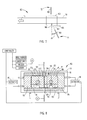
- Figs. 3 , 7-8 show a welding station 100 at an end of and as exiting a roll former.
- the sheet is shown as already having been formed in a roll former, and is traveling in a direction of travel D1.
- a weld box fixture 102 is positioned in line with the partially-formed beam 50.
- Top and bottom laser welders 103 are positioned at the welding station in a location where the weld box fixture will not interfere with their respective laser beams striking targeted abutting material of the beam 50.
- the bottom laser welder 103 is positioned slightly upstream of the weld box fixture 102, and its welding laser 104 is oriented at a downstream angle so that the welding laser beam 104 strikes the beam 101 at a desired location to heat and weld abutting material of the beam 101.
- the laser has a focal length of up to 36 inches, depending on the type of laser. There is no minimum distance of the laser from the weld location on the beam 101.
- the laser type could be gas (such as CO2), or could be solid state, fiber, or disc laser types.
- a maximum angle A1 of the laser 104 to the reinforcement beam 101 is about 15 degrees from vertical (i.e. from perpendicular to a side of the beam 50).
- a physical shield 105 is used, if necessary or desirable, to shield the laser source 106 from debris from the welding process.
- the physical shield 105 can be downstream air knives or air jets, or can include a physical panel.
- the adjustable weld box fixture 102 ( Fig. 8 ) is located at the welding station and is designed for setting and holding a final shape of the roll-formed beam during the welding step.
- the illustrated adjustable fixture 102 includes an external steel box frame 110, top and bottom external mandrels 111, 112, and adjustable side external mandrels 113, 114 that are inwardly-pressured by actuators 115, 116.
- the actuators can be dynamic or active (such as hydraulic cylinders), or they can be adjustable and passive, such as threaded bolts that can be adjusted to provide a desired amount of inward pressure to maintain a desired shape of the external mandrels within the weld box fixture 102.
- Two rods are shown extending from the actuator 115 through the frame 110 to a location where they are attached to the external mandrel 111.
- alternative connected and motivating arrangements can be constructed.
- Internal mandrels 117, 118 are located in each of the tubes 121, 122 of the double tube beam 120, and are anchored by cables 123, 124 that extend to an upstream anchor stanchion 125 located on the roll former where the sheet is laterally open sufficiently to position the anchoring stanchion 125 ( Fig. 3 ) for holding the cables 123, 124 ( Fig. 8 ).
- Beam 50 is illustrated, but it is contemplated that the beam could be like beam 50A or another modified beam.
- the illustrated internal mandrels 117, 118 each are split mandrels with opposing mandrel halves 126, 127 biased apart by a spring 128 (e.g. hydraulic, mechanical, or other spring).
- Internal mandrel 118 also includes opposing mandrel halves 130, 131 biased apart by hydraulic spring 132. However, it is contemplated that in some circumstances, a one-piece solid internal mandrel can be used on each side.
- a laser access opening is provided in the fixture box frame 110 and external mandrels 111,112, with the illustrated laser access opening 129 providing access for the laser beam through a bottom and top of the box frame 110 and through the top and bottom external mandrels 111, 112.
- the internal springs 128 and 132 and split internal mandrels 117, 118 in combination with the inward-biasing actuators 115, 116 and external mandrels 113, 114 cause the fixture to maintain a desired outer shape of the beam 101 as it passes through the weld station 100 and is welded.
- a slip plane P1 defined between the top external mandrel 111 and a top of the side external mandrels 113, 114.
- the slip plane P1 aligns with the front face of the beam 101 and is defined in part by the outboard surface of the tip of the front radiused end of the center leg
- the slip plane P2 aligns with a rear face of the beam 101 and is defined in part by the outboard surface of the tip of the rear radiused end of the center leg.
Landscapes
- Engineering & Computer Science (AREA)
- Physics & Mathematics (AREA)
- Optics & Photonics (AREA)
- Mechanical Engineering (AREA)
- Plasma & Fusion (AREA)
- Bending Of Plates, Rods, And Pipes (AREA)
- Laser Beam Processing (AREA)
- Blow-Moulding Or Thermoforming Of Plastics Or The Like (AREA)
- Butt Welding And Welding Of Specific Article (AREA)
- Shaping Of Tube Ends By Bending Or Straightening (AREA)
- Body Structure For Vehicles (AREA)
Abstract
Description
- This application claims benefit under 35 USC section 119(e) of provisional application serial no.
61/385,680, filed September 23, 2010 11827216.0 PCT/US2011/051025) filed on 9 September 2011 , the entire contents of which are incorporated herein by reference. - The present invention relates to bumper reinforcement beams used in vehicle bumper systems, where the beam is tubular and has a single (mono) center leg. The present invention also relates to roll forming apparatus and methods of forming said beams. However, the present invention is not believed to be limited to only bumper reinforcement beams for vehicles.
- Modem vehicle bumper systems typically include a reinforcement beam designed for strength and impact characteristics in order to meet government and insurance industry standards for particular vehicles, but also designed to minimize overall vehicle weight, to maximize strength-to-weight ratios, to fit within confined vehicle package spaces, and to satisfy vehicle aesthetic and functional requirements at front and rear ends of vehicles. Concurrently, the processes and methods of manufacturing the beams preferably minimize undesired product dimensional and quality variations, while also minimizing manufacturing cost, optimizing manufacturability and minimizing scrap. Roll forming processes and methods have proved to be particularly effective at producing high volume runs of bumper reinforcement beams with competitive cost and high dimensional consistency. However, the industry is very competitive, such that even small improvements can be important.
- Further, many of the desired features above are conflicting, such that it is not clear how to improve a particular bumper reinforcement beam, or how to improve the roll forming process for making the beam. For example, a heavier beam may be stronger, but would cause an unacceptable increase in vehicle weight. High strength materials may be preferred, but they are expensive, difficult to form, and cause high wear on tooling. Accurate control over positioning of sheet edges during the roll forming process is desired to facilitate an accurate beam cross sectional shape, to reduce tolerances along the edges so that excess material along the edges can be reduced in order to minimize beam weight, and to facilitate consistent contact during welding. However, this can require extra roll forming steps and stations as well as additional tooling, hardware and software controls, each of which increase capital investment and make the roll forming process more complex. The above beams include two sheet edges formed against other material of the sheet, with each being welded by a welder to permanently form the tubular shape of the beams. However, welders take up space along the roll form apparatus, especially where the welders are positioned at different stations along a length of a roll form apparatus, thus increasing floor space requirements considerably, as well as capital investment. Nonetheless, it is difficult to weld in two opposing sides of a beam due to flying debris adversely affecting one or both of the welders. Notably, welds must be consistent and reliable in order to provide reliable and consistent impact strength in the bumper reinforcement beams and in the related bumper systems.
- In one aspect of the present invention, a reinforcement beam includes a beam formed from a single sheet and including first and second tubes sharing a common wall and having coplanar aligned front walls and coplanar aligned rear walls, each front wall including a channel rib therein, the sheet including a first edge with a first radiused portion and first tip, a second edge with a second radiused portion and second tip, a third radiused portion connecting one of the aligned front walls with one end of the common wall, and a fourth radiused portion connecting one of the rear walls with another end of the common wall, the first and third radiused portions being welded together at a first weld and forming a front crevice rib having a cavity depth at least two times a thickness of the sheet, and the second and fourth radiused portions being welded together at a second weld and forming a rear crevice having a cavity depth at least two times the thickness of the sheet, the channel ribs and the front crevice rib forming ribs that stiffen a front face of the beam.
- In another aspect of the present invention, an apparatus is provided for forming a sheet into a beam having four exterior walls and a common center leg extending between an opposing two of the walls, the four exterior walls defining a rectangular cross section, and the center leg dividing the cross section into first and second adjacent tubes, the center leg having radiused ends each defining slip planes perpendicular to the center leg, and the sheet having edges that abut the radiused ends. The apparatus includes a roll former including roll form stations with rollers for forming the sheet into the beam with the four exterior walls and the common center leg, the roll former including a welding station with welders and a weld box fixture, the weld box fixture including a fixture frame, external mandrels supported by the fixture frame and supporting the four exterior walls in a desired accurate shape, two of the external mandrels being movable and opposing, and including at least one actuator operably connected to the two opposing external mandrels for moving the opposing external mandrels into engagement with associated opposing ones of the four exterior walls. The apparatus further includes internal mandrels in each of the first and second adjacent tubes that are supported by upstream anchor lines so that the internal mandrels remain generally adjacent the external mandrels. By this arrangement, the internal and external mandrels, in combination with a bias of the springs and a counter bias of the two opposing external mandrels, control a shape of the beam by flexure and movement of material of the sheet along the slip planes to thus actively maintain an accurate shape when in the weld box fixture during a welding process of the welder.
- In a narrower aspect, the internal mandrels each include opposing halves and a spring biasing the opposing halves apart against the external mandrels and against a force of the actuator.
- In another aspect of the present invention, an apparatus is provided for forming a sheet into a beam having four exterior walls and a common center leg extending between an opposing two of the walls, the four exterior walls defining a rectangular cross section, and the center leg dividing the cross section into first and second adjacent tubes, the center leg having radiused ends each defining slip planes perpendicular to the center leg, and the sheet having edges that abut the radiused ends. The apparatus includes a roll former including roll form stations with rollers for forming the sheet into the beam with the four exterior walls and the common center leg, the roll former including a welding station with welders and a weld box fixture, the weld box fixture including a fixture frame, external mandrels supported by the fixture frame and supporting the four exterior walls in a desired accurate shape, two of the external mandrels being movable and opposing, and including at least one actuator operably connected to the two opposing external mandrels for moving the opposing external mandrels into engagement with associated opposing ones of the four exterior walls, two others of the external mandrels being fixed and opposing such that the two other external mandrels generally fix a distance between the opposing two walls between which the center leg extends. By this arrangement, the external mandrels in combination with a bias of the two opposing external mandrels, control a shape of the beam by flexure and movement of material of the sheet along the slip planes to thus actively maintain an accurate shape when in the weld box fixture during a welding process of the welder.
- In another aspect of the present invention, an apparatus includes a roll former including roll form stations with rollers for forming the sheet into the continuous beam with the four exterior walls and the common center leg, the roll former including a welding station with a welder and a weld box fixture, the welder generating an upwardly-angled laser beam for welding the continuous beam to permanently fix the cross section and being positioned under the continuous beam at a location upstream or downstream from the weld box fixture so that the laser beam welds within a down-facing crevice formed by one of the radiused edges abutting one of the radiused ends. By this arrangement, the welder welds the continuous beam from a position under the continuous beam yet is positioned away from falling debris.
- In another aspect of the present invention, an apparatus includes a roll former including a roll former including roll form stations with rollers for forming the sheet into the continuous beam with the four exterior walls and the common center leg, the roll former including a single welding station with a top welder and a bottom welder and a weld box fixture, the welders welding the continuous beam to permanently fix the cross section by welding simultaneously in the welding station at upper and lower locations on the beam. By this arrangement, welding is done in the single welding station and not in multiple weld stations.
- In another aspect of the present invention, an apparatus includes a roll former including first roll form stations with first sets of rollers forming the center leg of the sheet and outboard wings of the sheet, with the outboard wings having portions adjacent the center leg that extend perpendicular to the center leg and that are joined to the center leg by the radiused ends, and with the outboard wings also having the radiused edges formed thereon. The roll former further includes additional roll form stations with additional sets of rollers forming the outboard wings into first and second tubes with the center leg being a common wall forming part of each of the first and second tubes. The roll former includes top and bottom welders welding the radiused edges to the radiused ends.
- Related methods also form a part of the present invention.
- These and other aspects, objects, and features of the present invention will be understood and appreciated by those skilled in the art upon studying the following specification, claims, and appended drawings.
-
-
Fig. 1 is a top view of a bumper reinforcement beam that is tubular and includes a single center leg. -
Fig. 2 is a cross sectional view along line II-II inFig. 1 . -
Fig. 3 is a view of the roll forming apparatus for performing the present roll forming process. -
Fig. 4 is a series of cross sections labeled S1-S33 showing a shape of the original sheet at each forming step when forming the beam ofFig. 1 . -
Fig. 5 is a cross section of the beam inFigs. 1-2 including seam tracking discs forming part of a weld station. -
Fig. 6 is a modified beam similar toFigs. 1-2 but having a modified cross section. -
Fig. 7 is a side view showing a welding station near an end of the roll forming process. -
Fig. 8 is a cross section through the welding station ofFig. 7 , showing a pressure box fixture for holding the roll-formed beam's final shape during a simultaneous double-weld step. - A bumper reinforcement beam 40 (
Fig. 1 ) includes atubular reinforcement beam 50 for a vehicle bumper system, andmounts 41 attached to thebeam 50 to facilitate attachment to a vehicle frame, such as for use in a front bumper system (illustrated inFig. 1 ) or rear bumper system of a vehicle. The illustratedbeam 50 includes alongitudinal center section 42 curved at a first radius R1 and longitudinal outer ends curved at a tighter second radius R2 in order to match an aerodynamic shape of a particular vehicle. However, it is contemplated that the present inventive concepts can be used on any beam, whether linear or swept, and whether consistently curved/swept with a single radius or having different longitudinally-curves ("sweeps"). - The
present beam 50 is made of sheet steel material having a thickness of 0.8mm to 1.4mm and a tensile strength of about 800 to 2000 MPa (i.e. about 120 to 290 ksi). The illustrated beam is about 80mm high and 40mm deep (in vehicle-mounted position), with two channel ribs being formed in the beam's front face (one over each tube). Each illustrated channel rib is about 8-10mm deep and 8-10mm wide, and includes a rounded bottom. However, it is contemplated that the present beam can be made of different materials, including AHSS (Advanced High Strength Steels) and that it can be made from a sheet having a thickness of about 0.8mm-3.0mm thick (or such as 0.8mm to 1.4mm thickness), and can be made in different beam cross sectional sizes, such as about 80mm-150mm high, and 30mm-60mm deep, and having a length equal to or slightly greater than a distance between vehicle mounts/bumper frame rail tips. - The present beam 50 (
Fig. 3 ) is formed from a single sheet of steel metal on a roll forming apparatus via a series of paired rolls in roll forming stations, with each station performing a forming operation, such as shown by the roll-formed flower pattern of steps 1-33 inFig. 4 . During the process, a single sheet is formed to have adjacent tubes formed on opposite sides of a single center wall (sometimes called a "mono" wall or "center leg," herein). The roll former includes a first region of forming rolls in stations S1-S7, including forming a center section (i.e. the center wall) with outer sections of the sheet extending outwardly and generally perpendicular to the center wall. Radiused sheet edges are also formed in steps S1-S7. The roll former further includes a second region of forming rolls in stations S8-S33 forming first and second tubes on each side of the center leg and sharing the center leg as a common wall. The channel ribs are substantially formed in steps S8-S12, and help in controlling a lateral position of the sheet as it traverses along the roll form apparatus. Laser welding occurs at or after station S33. Alternatively, the welding can occur in two separate steps, such as in a roll forming process where the first tube is formed halfway through the process (well before the last forming station). - Specifically, as illustrated, slightly less than "half" of the sheet is deformed in a first direction (illustrated as clockwise in
Fig. 4 ) into a first tube with a first radiused edge of the sheet abutted against a radiused end of the center wall (and welded), and an opposite "half" of the sheet is deformed in an opposite second direction (such as counter-clockwise) into a second tube with a second radiused edge abutted against the other radiused end of the center wall (and welded). The line of contact for welding on the first radiused edge is at an end of the radius where a terminal tip of the sheet becomes "flat." Similarly, the line of contact of the radiused end of the center wall is at an end of the center wall where the center wall becomes "flat." However, it is desirable to have the radius be the primary contact so that the laser beam of the welding process has optimal conditions for making a consistent weld. Notably, the welding process includes a laser beam entering the crevice and heating material at the abutting line contact formed by the radiused end and radiused edge. For this reason, it may be desirable that the terminal tips of the sheet edges be formed so that they do not cause a gap at the bottom of the crevice despite process variations, which gap would (could) adversely affect welding, depending on a size of the gap. - Notably, the welding box fixture assists with setting the line contact and with setting a desired abutting pressure for the welding process at the line contact. The mating materials are held abuttingly against each other by the weld fixture shown in
Fig. 8 , as discussed below, to facilitate a good weld. A radiused shape of the edges allows good contact, yet allows the edges to flex, slide, and bend (caused by forces generated in the weld box fixture), especially along slip plans P1 and P2, allowing the fixture to "set" and maintain a desired cross sectional shape in the weld station. This arrangement facilitates good welding, and potentially decreases the criticality of perfect dimensionality of the edges. Concurrently, the edges of the sheet include a tip section of material inside the beam that extends away from the weld line. As noted above, the free end of the tip section is necessary to assure that there is sufficient material to weld despite material variations along the edge and process variations. However, excess material in the free end of the tip section results in waste and added weight to the bumper beam. By accurately controlling contact and engagement of the edges and abutting material, a length of the "free end" can be minimized, thus reducing an overall weight of the beam to a minimum. It is noted that even ounces of reduced weight can be important to automotive engineers and vehicle designers. The illustrated "free end" is expected to be less than about 4mm, but it is contemplated that it potentially could be reduced such as to 2 mm, depending on particular process parameters and functional requirements of the beam. - As noted, the radiused edges of the sheet advantageously facilitate and allow for consistent and forgiving abutting engagement as they extend into contact with and are welded to mating radiused (bent) corners on the center leg of the beam. The double radius of the edges and of the center leg ends allows the two sections of material to reliably engage in line contact and engage within a desired range of abutment force, thus better accommodating dimensional variations during the manufacturing process. This configuration facilitates good line contact of the abutting material sections and thus facilitates good welding despite dimensional and process variations. At the same time, the radiused edges and "free ends" of the edges are recessed into the front and rear faces of the beam so that vertical planes defined by the front and rear surfaces of the beam are not uninterrupted by any outwardly-protruding edge of the sheet, which can be important to meeting vehicle manufacturer specifications. Also, the center leg is formed from a center of the sheet (and not from a side edge of the sheet). By forming the center leg first and by making it from a center of the sheet, the roll form process is more balanced and controlled, making it easier to control a lateral position of the sheet. In other words, "wandering" of the sheet in the roll former is reduced due to first forming the center leg, since the center leg then acts as a "center anchor" during later forming of the sheet. This increased accurate positional control of the sheet results in the ability to further reduce tolerances of the "free end" of the edges, since a wide tolerance is not required. It is contemplated that the "free ends" of the edges can be reduced to 4mm or less, and even as low as 2mm or less, depending on process controls and characteristics of the sheet and roll forming process.
- The
tubular reinforcement beam 50 with center leg is particularly suited for use as a reinforcement beam in a vehicle bumper system due to its high strength-to-weight ratio, due to its resistance to longitudinal bending due to an impact inward of its ends, and due to its torsional resistance to rotational forces such as from a vertically-off-center impact. - As noted above, the beam 50 (
Fig. 2 ) is formed from a single unitary sheet in a continuous roll forming process (Fig. 6 ). Thebeam 50 includes first andsecond edges wall section 56 being a common shared wall. The wall sections 53-55 and 57-59 combine to form a tubular shape with a center leg formed by horizontally-extending wall section 56 (when in a vehicle-mounted position), and withwall sections wall sections first edge 51 is deformed to form a radius CR1 of about 3-4mm, with its tip 51' (i.e. "free end" having a length of about 4mm or potentially as small as 2mm) extending so that aninner surface 61 of thefirst edge 51 lies parallel thecenter wall section 56. The radius CR1 and associated radiused corner 62 (formed by the fourth and fifth wall sections 56-57 on the front face of the beam) engage and are welded to permanently set the first tube. - In
beam 50, thesecond edge 52 is also deformed inwardly to form a radius similar to radius CR1 (such as about 3-4mm in the illustrated beam), but with its terminal tip 52' extending parallel thecenter wall section 56. The radius CR1 engages and is welded to an associatedradiused corner 64 formed by the fourth andthird wall sections beam 50 has a cross section that is generally rectangular, with a center leg dividing the rectangle into adjacent equal-sized first and second tubes. This cross section has been found to provide excellent bending stiffness, torsional stiffness, and a relatively high strength-to-weight ratio. - The illustrated
first wall section 53 includes a channel rib 65 (i.e. an inwardly formed depression, also sometimes called a "power rib") that further stiffens thewall section 53 and accordingly stiffens the front face of the beam and stiffens the first tube section. The illustratedchannel rib 65 is generally centered alongwall section 53 and has a width diameter about 10%-40% of a width of the wall section 53 (or more preferably about 20%-30% of the width) and has a depth about equal to its width diameter. Thefifth wall section 57 also includes a channel rib 66 (similar in size, shape, and location to rib 65) that stiffens thewall section 57, and accordingly stiffens the front face of the beam and the second tube section. The radii CR1 formed by thefirst edge 51 and tip 51A and by thesecond edge 52 and tip 52A have center points located inside the respective tubes formed thereby. The bottoms of the illustrated channel ribs are semicircularly shape. Nonetheless, it is contemplated that a depth and size of the channel ribs can be made shallow, deeper, wider, narrower, flat-bottomed, or otherwise modified to satisfy specific functional requirements of a beam. - Notably, the radiused shape of the
edges beam 50 and thus stabilizes the front and rear walls/faces of thebeam 50 in a manner not totally unlike thechannel ribs front edge 51 and associated corner combine with the twochannel ribs 65 to effectively form three ribs on a face of thebeam 50, each stiffening the bending strength and torsional strength of the beam. Testing has shown that a stiffness of the beam can be increased sufficiently to offset any additional material weight added by virtue of the channel ribs requiring a wider sheet to manufacture the beam. The crevice rib is generally aligned with the center wall, and the cavity it defines is about 3-4 times as deep as a cross sectional thickness of the material of the sheet. Specifically, the cavity of the illustrated crevice rib is about 3-4 mm deep, based on a sheet material thickness of about 0.8mm-1.2mm. The laser weld is located at a bottom of the crevice where the material first comes into abutting contact. - It is contemplated that the
welds laser welders 72 and 73 (Fig. 3 ). Thepresent welders welds 70 and 71 (Fig. 2 ) are formed at the outboard abutting material in the crevice, such that the welds are spaced slightly from the terminal ends (i.e. the "free ends") of the first and second edges, such as about 4mm, or potentially down to about 2mm. The illustrated curved abutting inter-engagement of sheet material has been found to be forgiving and allows some dimensional variation and dimensional control within the welding fixture without adversely affecting the line contact and the welding operation. Even though thepresent welders - Notably, the beam, including its cross sectional profile and the
welds Fig. 4 ). In particular, persons skilled in the art of roll forming manufacture and design will recognize the value of the perpendicularity of the center wall in step S7, and also the value of the perpendicularity of the outer walls in step S21, and the minimization of roll forming steps thereby facilitated. - The related method of manufacturing a tubular reinforcement beam 50 with center wall section 56 for a bumper reinforcement beam 40 (see the roll former in
Fig. 3 , and the beam inFigs. 1-2 ) includes steps of: providing a sheet 49 (seeFig. 3 ) including first and second edges 51-52 (Fig. 2 ) and seven wall sections 53-59 extending sequentially therebetween; bending the center wall to a perpendicular orientation to the remaining material (see steps S2-S7), bending the edge tips (step S3-S7) and forming the channel ribs 65, 66 (started in steps S3-S9 and finishing the channel ribs in steps S10-S12), bending the first through fourth wall sections 53-56 to form a first tube and bending the fourth through seventh wall sections 56-59 to form an adjacent second tube (half formed in steps S3-S21 and finishing same in steps S22-S33); welding the first edge 51 to the associated radiused corner 62 and welding the second edge 52 to the associated radiused corner 64 while maintaining an accurate cross sectional shape of the continuous beam in a weld fixture (seFigs. 7-8 ); deforming the continuous beam to a longitudinally curved ("swept") shape in the sweeping station, and cutting off the beam segments to length in a cutoff station to form individual bumper reinforcement beams. - Notably, the
channel rib 65 in thefirst wall section 53 andchannel rib 66 in the fifth wall section combine with the crevice at a center of the beam front (over the center wall) to provide a three channel rib formation on a face of the beam. This provides excellent torsional and bending strength in the beam, as noted above. In particular, testing has shown that channels and ribs providing stability to a face of the beam can improve impact strengths significantly and provide increased consistency of impact strength (and consistency of energy absorbing ability) without increasing beam weight, which is an unexpected and surprising result. The improvement in impact strength is attributed to several factors. For example, the present beam's weight is not increased over a similar sized beam not having channel ribs, because the present beam uses a thinner sheet material while still providing a similar or improved impact test result. Notably, thinner materials can tend to unpredictably/prematurely kink and catastrophically collapse due to the dynamics that occur during an impact against thin sheet material, potentially increasing variability and inconsistency of impact strengths during testing. However, the channel ribs and crevice rib in the front of the present beam helps stabilize the tubular structure of the beam, thus providing improved test results even when a thinner sheet material is used. This improvement was not expected given the fact that the channel ribs and crevice rib are in the face of the beam. Part of the reason it was not expected is because the face-located channel ribs and crevice ribs cause some sheet material to be located inward closer to a bending moment's centerline (rather than farther away from the centerline). Notably, material located closer to a bending moment's centerline contributes less to the beam's bending moment, thus potentially reducing the bending moment of inertia for the beam. However, due to the dynamics of impacts, stability of beam walls can be very important to beam impact performance. Also, some bumper testing causes vertically unbalanced torsional forces (such as when a test impactor device strikes a beam higher than its centerline). - A related apparatus 88 (
Fig. 3 ) for manufacturing atubular reinforcement beam 50 withcenter wall section 56 for abumper reinforcement beam 40 comprises aroll mill 89 with in-line sweep station 90 andcutoff 91. Theroll mill 89 includes rolls constructed to form asheet 49 including first and second edges 51-52 and seven wall sections 53-59 extending sequentially therebetween. The rolls include a first region ofroll forming stations 92 with sets of rolls positioned to form the center leg with outer wings of the sheet extending generally perpendicularly from the center leg. The first region of theroll forming stations 92 also forms the radiused edges of the sheet. A second region of roll forming stations 92' include roll sets positioned and configured to bend the first through fourth wall sections 53-56 to form a first tube and to bend the fourth through seventh wall sections 56-59 to form an adjacent second tube, with the single center leg being common to both tubes. First andsecond welders first edge 51 to the associated inner surface of radiusedcorner 62, and to weld thesecond edge 52 to the associated radiusedcorner 64. Thefirst welder 72 is positioned above the beam, and thesecond welder 73 is positioned below the beam with its laser beam oriented at an angle, as described below. - It is noted that the present apparatus can utilize a roll mill with horizontal axes supporting forming rolls, or alternatively can utilize a roll mill with vertical axes supporting forming rolls. In the vertical axis mill, the laser welders would potentially operate from opposing sides of the beam or partially above the beam. An advantage of a vertical axis roll mill is that gravity can be used to cause debris and dirt to fall away from the welding sites, since the welder is positioned off to a side and/or above the welding. In the horizontal axis roll mill, the lasers operate from top and bottom positions relative to the beam. The bottom position of one of the welders potentially causes a problem with falling debris, but this problem is solved by the present innovation as discussed below.
- As shown by the illustrated version in
Figs. 3 and4 , the apparatus is preferably constructed where both welds are made at a single station with the welding being done simultaneously. Onewelder 72 is positioned above the welding location and asecond welder 73 is positioned below but significantly upstream of (or downstream of) the weld location. The bottom welder is positioned and shielded so that the welder is not detrimentally affected by flying and falling debris. For example, the illustrated bottom welder is located upstream of the actual welding site by 15 degrees from vertical. Also, if necessary (depending on a distance of the laser beam generating device from the weld location), a shield can be used to physically shield the laser generating device from the weld. The illustrated shield is a physical barrier located so that it does not interfere with the laser beam (which defines a line), but so that the laser generating apparatus is protected from falling debris (which tends to define an arc as the debris initially moves laterally and then falls by gravity toward an end of its falling path). It is contemplated that the shield will also include an air shield provided by a directed air stream. Notably, a focal length of a laser welder beam can be up to 36 inches, and the laser beam could be any of several different types, such as gas (CO2), solid state, fiber, or disc. - It is noted that in the steps shown in
Fig. 4 , the center leg is initially formed from a center of the sheet to a perpendicular orientation relative to a horizontal plane (which extends along a line level of the roll former) in the first few steps S1-S7. This anchors the sheet and keeps the sheet centered in the roll forming process, thus eliminating (or greatly reducing) a tendency of the sheet to wander or slide laterally during the forming process. It is noted that, due to the high strength properties of the present sheet and due to its thickness and width, large lateral forces are generated during the roll forming process. By first forming the center leg to a perpendicular state, control of the sheet's lateral position is much easier and is more inherently controlled/ controllable. Also, radii are formed into edges of the sheet in steps S1-S7. Thereafter, the adjacent tubes are formed on opposite sides of the common center leg. As a result in the present process ofFig. 4 , the number of roll forming steps can be reduced to as few as 33 steps (seeFig. 4 ) even when forming a sheet having 290 ksi+ tensile strength, which is considered to be a dramatic and surprising and unexpected improvement from known methods. Notably, fewer forming steps can be very beneficial, since the reduced number of steps can reduce tooling costs (i.e. fewer forming rolls necessary), reduce a length of the roll form apparatus (i.e. fewer roll form stations), and reduce overall processing time (i.e. a shorter cycle time from the initial flat sheet to the double tube beam shape). -
Fig. 5 illustrates a seam tracking disc 90' used to track and control thecrevice 80. (InFig. 5 , the disc 90' is exploded away, but it is contemplated that the disc will physically engage thebeam 50 and track along the crevice.) The disc 90' tracks a valley of thecrevice 80 to facilitate the welding process. Specifically, the disc 90' is a rotating disc, resembling a pizza cutter, that rides inside the area for the continuous weld seam. The laser welder locates off of this disc in the weld valley. As illustrated, a disc 90' can be used to track crevices at both the top and bottom of thebeam 50. -
Fig. 6 is a cross section of the modifiedbeam 50A similar toFig. 2 but with the tubes having different widths. Specifically, one tube ofbeam 50A is about twice a width of the other tube. However, they share a common center wall. Further, they both have a channel rib of similar size and shape, and also there is a crevice rib formed over the center leg. In thebeam 50A, similar and identical features, characteristics, and components are identified by using identical numbers but with a letter (such as "A"). This is done to reduce redundant discussion. It will be understood by persons skilled in the art of bumper reinforcement beams and related manufacturing processes that thebeam 50A can and does incorporate many features ofbeam 50, such that an individual discussion of numbers inbeam 50A is not believed to be necessary. -
Figs. 3 ,7-8 show awelding station 100 at an end of and as exiting a roll former. InFig. 7 , the sheet is shown as already having been formed in a roll former, and is traveling in a direction of travel D1. Aweld box fixture 102 is positioned in line with the partially-formedbeam 50. Top andbottom laser welders 103 are positioned at the welding station in a location where the weld box fixture will not interfere with their respective laser beams striking targeted abutting material of thebeam 50. Thebottom laser welder 103 is positioned slightly upstream of theweld box fixture 102, and itswelding laser 104 is oriented at a downstream angle so that thewelding laser beam 104 strikes thebeam 101 at a desired location to heat and weld abutting material of thebeam 101. The laser has a focal length of up to 36 inches, depending on the type of laser. There is no minimum distance of the laser from the weld location on thebeam 101. For example, it is contemplated that the laser type could be gas (such as CO2), or could be solid state, fiber, or disc laser types. A maximum angle A1 of thelaser 104 to thereinforcement beam 101 is about 15 degrees from vertical (i.e. from perpendicular to a side of the beam 50). Aphysical shield 105 is used, if necessary or desirable, to shield thelaser source 106 from debris from the welding process. Thephysical shield 105 can be downstream air knives or air jets, or can include a physical panel. - The adjustable weld box fixture 102 (
Fig. 8 ) is located at the welding station and is designed for setting and holding a final shape of the roll-formed beam during the welding step. The illustratedadjustable fixture 102 includes an externalsteel box frame 110, top and bottomexternal mandrels external mandrels actuators weld box fixture 102. Two rods are shown extending from theactuator 115 through theframe 110 to a location where they are attached to theexternal mandrel 111. However, it is contemplated that alternative connected and motivating arrangements can be constructed. -
Internal mandrels tubes double tube beam 120, and are anchored bycables upstream anchor stanchion 125 located on the roll former where the sheet is laterally open sufficiently to position the anchoring stanchion 125 (Fig. 3 ) for holding thecables 123, 124 (Fig. 8 ).Beam 50 is illustrated, but it is contemplated that the beam could be likebeam 50A or another modified beam. The illustratedinternal mandrels Internal mandrel 118 also includes opposing mandrel halves 130, 131 biased apart byhydraulic spring 132. However, it is contemplated that in some circumstances, a one-piece solid internal mandrel can be used on each side. A laser access opening is provided in thefixture box frame 110 and external mandrels 111,112, with the illustrated laser access opening 129 providing access for the laser beam through a bottom and top of thebox frame 110 and through the top and bottomexternal mandrels - The
internal springs internal mandrels actuators external mandrels beam 101 as it passes through theweld station 100 and is welded. Notably, there is a slip plane P1 defined between the topexternal mandrel 111 and a top of the sideexternal mandrels external mandrel 112 and a bottom of the sideexternal mandrels beam 101 and is defined in part by the outboard surface of the tip of the front radiused end of the center leg, and the slip plane P2 aligns with a rear face of thebeam 101 and is defined in part by the outboard surface of the tip of the rear radiused end of the center leg. In the welding station, pressure from the internal and external mandrels of the welding fixture cause sheet material to move and deform to an accurate known position along the slip planes P1 and P2. This improves dimensional consistency and accuracy of a cross sectional shape of the beam prior to (and during) the welding process. Also, by this arrangement, the pressure on the abutting surfaces where the welds will occur can be more accurately and consistently controlled for an optimal weld condition. - It is to be understood that variations and modifications can be made on the aforementioned structure without departing from the concepts of the present invention, and further it is to be understood that such concepts are intended to be covered by the following claims unless these claims by their language expressly state otherwise.
- The application further discloses:
- i) A reinforcement beam comprising:
- a beam formed from a single sheet and including first and second tubes sharing a common wall and having coplanar aligned front walls and coplanar aligned rear walls, each front wall including a channel rib therein, the sheet including a first edge with a first radiused portion and first tip, a second edge with a second radiused portion and second tip, a third radiused portion connecting one of the aligned front walls with one end of the common wall, and a fourth radiused portion connecting one of the rear walls with another end of the common wall, the first and third radiused portions being welded together at a first weld and forming a front crevice rib having a cavity depth at least two times a thickness of the sheet, and the second and fourth radiused portions being welded together at a second weld and forming a rear crevice having a cavity depth at least two times the thickness of the sheet, the channel ribs and the front crevice rib forming ribs that stiffen a front face of the beam.
- ii) The reinforcement beam defined in paragraph i) wherein, optionally, the front crevice is generally centered over the aligned wall, and forms with said channel ribs a three rib reinforced front face on the beam.
- iii) The reinforcement beam defined in paragraph i) wherein, optionally, the front weld is formed at a bottom of the first crevice immediately adjacent a location where the first and third radiused portions first come into abutting contact, the first tip extending inside the beam and away from the weld less than about 4 mm.
- iv) The reinforcement beam defined in paragraph i) wherein, optionally, the front weld is a continuous strip of bonded material formed by laser welding.
- v) The reinforcement beam defined in paragraph i) wherein, optionally, the sheet has a material thickness of is less than about 1.2 mm.
- vi) The reinforcement beam defined in paragraph i) wherein, optionally, the sheet has a tensile strength of greater than 250 ksi.
- vii) The reinforcement beam defined in paragraph i) wherein, optionally, the channel ribs have a same shape and have a depth equal to their width.
There is also disclosed: - viii) An apparatus for forming a sheet into a beam having four exterior walls and a common center leg extending between an opposing two of the walls, the four exterior walls defining a rectangular cross section, and the center leg dividing the cross section into first and second adjacent tubes, the center leg having radiused ends each defining slip planes perpendicular to the center leg, and the sheet having edges that abut the radiused ends, comprising:
- a roll former including roll form stations with rollers for forming the sheet into the beam with the four exterior walls and the common center leg, the roll former including a welding station with welders and a weld box fixture, the weld box fixture including a fixture frame, external mandrels supported by the fixture frame and supporting the four exterior walls in a desired accurate shape, two of the external mandrels being movable and opposing, and including at least one actuator operably connected to the two opposing external mandrels for moving the opposing external mandrels into engagement with associated opposing ones of the four exterior walls; and
- internal mandrels in each of the first and second adjacent tubes that are supported by upstream anchor lines so that the internal mandrels remain generally adjacent the external mandrels;
- whereby, the internal and external mandrels, in combination with a bias of the springs and a counter bias of the two opposing external mandrels, control a shape of the beam by flexure and movement of material of the sheet along the slip planes to thus actively maintain an accurate shape when in the weld box fixture during a welding process of the welder.
- ix) The reinforcement beam defined in paragraph viii) wherein, optionally, the at least one actuator includes an adjustable threaded member.
- x) The reinforcement beam defined in paragraph viii) wherein, optionally, the internal mandrels each have opposing halves and a spring biasing the opposing halves apart against the external mandrels and against a force of the actuator.
There is also disclosed: - xi) An apparatus for forming a sheet into a beam having four exterior walls and a common center leg extending between an opposing two of the walls, the four exterior walls defining a rectangular cross section, and the center leg dividing the cross section into first and second adjacent tubes, the center leg having radiused ends each defining slip planes perpendicular to the center leg, and the sheet having edges that abut the radiused ends, comprising:
- a roll former including roll form stations with rollers for forming the sheet into the beam with the four exterior walls and the common center leg, the roll former including a welding station with welders and a weld box fixture, the weld box fixture including a fixture frame, external mandrels supported by the fixture frame and supporting the four exterior walls in a desired accurate shape, two of the external mandrels being movable and opposing, and including at least one actuator operably connected to the two opposing external mandrels for moving the opposing external mandrels into engagement with associated opposing ones of the four exterior walls, two others of the external mandrels being fixed and opposing such that the two other external mandrels generally fix a distance between the opposing two walls between which the center leg extends;
- whereby, the external mandrels in combination with a bias of the two opposing external mandrels, control a shape of the beam by flexure and movement of material of the sheet along the slip planes to thus actively maintain an accurate shape when in the weld box fixture during a welding process of the welder.
- xii) An apparatus for forming a sheet into a beam having four exterior walls and a common center leg extending between an opposing two of the walls, the four exterior walls defining a rectangular cross section, and the center leg dividing the cross section into first and second adjacent tubes, the center leg having radiused ends each defining slip planes perpendicular to the center leg, and the sheet having radiused edges that abut the radiused ends, comprising:
- a roll former including roll form stations with rollers for forming the sheet into the continuous beam with the four exterior walls and the common center leg, the roll former including a welding station with a welder and a weld box fixture, the welder generating an upwardly-angled laser beam for welding the continuous beam to permanently fix the cross section and being positioned under the continuous beam at a location upstream or downstream from the weld box fixture so that the laser beam welds within a down-facing crevice formed by one of the radiused edges abutting one of the radiused ends;
- whereby, the welder welds the continuous beam from a position under the continuous beam yet is positioned away from falling debris.
- xiii) An apparatus for forming a sheet into a beam having four exterior walls and a common center leg extending between an opposing two of the walls, the four exterior walls defining a rectangular cross section, and the center leg dividing the cross section into first and second adjacent tubes, the center leg having radiused ends each defining slip planes perpendicular to the center leg, and the sheet having radiused edges that abut the radiused ends, comprising:
- a roll former including roll form stations with rollers for forming the sheet into the continuous beam with the four exterior walls and the common center leg, the roll former including a single welding station with a top welder and a bottom welder and a weld box fixture, the welders welding the continuous beam to permanently fix the cross section by welding simultaneously in the welding station at upper and location locations on the beam;
- whereby welding is done in the single welding station and not in multiple weld stations.
- xiv) An apparatus for forming a sheet into a beam having four exterior walls and a common center leg extending between an opposing two of the walls, the four exterior walls defining a rectangular cross section, and the center leg dividing the cross section into first and second adjacent tubes, the center leg having radiused ends each defining slip planes perpendicular to the center leg, and the sheet having radiused edges that abut the radiused ends, comprising:
- a roll former including first roll form stations with first sets of rollers forming the center leg of the sheet and outboard wings of the sheet, with the outboard wings having portions adjacent the center leg that extend perpendicular to the center leg and that are joined to the center leg by the radiused ends, and with the outboard wings also having the radiused edges formed thereon;
- the roll former further including additional roll form stations with additional sets of rollers forming the outboard wings into first and second tubes with the center leg being a common wall forming part of each of the first and second tubes; and
- top and bottom welders welding the radiused edges to the radiused ends.
- xv) A tubular reinforcement beam with center leg for a vehicle bumper system, comprising:
- a sheet including first and second edges and seven wall sections extending sequentially therebetween, the first thru fourth wall sections forming a first tube and the fourth thru seventh wall sections forming an adjacent second tube, the first edge being deformed inwardly but with its tip extending outward at an angle so that an inner surface of the first edge engages and is welded to an associated radiused corner formed by the fourth and fifth wall sections, the second edge being deformed inwardly but with its tip extending outward at an angle so that an inner surface of the second edge engages and is welded to an associated radiused corner formed by the fourth and third wall sections.
- xvi) The beam defined in paragraph xv), wherein, optionally, the first wall section includes a channel rib.
- xvii) The beam defined in paragraph xvi), wherein, optionally, the fifth wall section includes a channel rib.
- xviii) The beam defined in paragraph xv), wherein, optionally, the first edge and associated tip defines a radius with a centerpoint at or outboard of a front face of the beam.
- xix) The beam defined in paragraph xv), wherein, optionally, the beam includes welds located on first and second edges and that are spaced from terminal ends of the first and second edges.
There is also disclosed: - xx) A method of manufacturing a tubular reinforcement beam with center leg for a vehicle bumper system, comprising steps of:
- providing a sheet including first and second edges and seven wall sections extending sequentially therebetween;
- bending the first thru fourth wall sections to form a first tube, and bending the fourth thru seventh wall sections to form an adjacent second tube;
- deforming the first edge inwardly but with its tip extending outward at an angle so that an inner surface of the first edge engages an associated radiused corner formed by the fourth and fifth wall sections, deforming the second edge inwardly but with its tip extending outward at an angle so that an inner surface of the second edge engages an associated radiused corner formed by the fourth and third wall sections;
- welding the first edge to the associated radiused corner; and
- welding the second edge to the associated radiused corner.
- xxi) The beam defined in paragraph xx), wherein, optionally, the step of bending includes forming in the first wall section a channel rib.
- xxii) The beam defined in paragraph xxi), wherein, optionally, the step of bending includes forming in the fifth wall section a channel rib.
- xxiii) The beam defined in paragraph xx), wherein, optionally, the step of deforming the first edge includes forming a radius with centerpoint at or outboard of a front face of the beam.
- xxiv) The beam defined in paragraph xx), wherein, optionally, the step of welding the first and second edges includes welding them at locations spaced from respective terminal ends of the first and second edges.
There is also disclosed: - xxv) An apparatus for manufacturing a tubular reinforcement beam with center leg for a vehicle bumper system, comprising:
- a roll mill with rolls constructed to form a sheet including first and second edges and seven wall sections extending sequentially therebetween;
- the rolls including first rolls positioned and configured to bend the first thru fourth wall sections to form a first tube, and second rolls positioned and configured to bend the fourth thru seventh wall sections to form an adjacent second tube;
- the rolls further including third rolls positioned and configured to deform the first edge
- inwardly but with its tip extending outward at an angle so that an inner surface of the first edge engages an associated radiused corner formed by the fourth and fifth wall sections, and including fourth rolls positioned and configured to deform the second edge inwardly but with its tip extending outward at an angle so that an inner surface of the second edge engages an associated radiused corner formed by the fourth and third wall sections;
- a first welder positioned to weld the first edge to the associated radiused corner; and
- a second welder positioned to weld the second edge to the associated radiused corner.
Claims (21)
- A method of roll forming a tubular reinforcement beam for a vehicle, comprising:providing a sheet that includes a generally planar body extending laterally between a first edge and a second edge of the sheet;providing a roll former that includes at least a first set of rollers and a second set of rollers that are configured to sequentially receive the sheet;bending the sheet with the first set of rollers to form a center wall section in generally perpendicular orientation relative to first and second portions of the sheet that extend in opposing directions from respective first and second ends of the center wall section;bending the first and second edges of the respective first and second portions of the sheet to form a radius on each of the first and second edges;bending the first and second portions of the sheet to engage the first edge with the second end of the center wall and the second edge with the first end of the center wall to define a first tube and an adjacent second tube, wherein the radii of the first and second edges each contact the center wall section to define a valley for receiving a weld; andwelding in the valley to attach the first and second edges respectively with the second and first ends of the center wall.
- The method of claim 1, wherein the first and second portions are each bent to form a front wall section, an outer wall section, and a rear wall section that together with the center wall section define the adjacent first and second tubes.
- The method of claim 2, wherein the front wall sections and the rear wall sections are each substantially coplanar upon engagement of the first and second edges with the center wall, such that the first and second tubes together have a generally rectangular cross section.
- The method of claim 3, further comprising:bending the first and second portions of the sheet to form a channel rib in each of the front wall sections, before the first and second edges engage the center wall.
- The method of claim 4, wherein the center wall is configured to maintain a balanced roll forming operation during later forming of the sheet, such that after formation of the channel ribs, the first and second portions of the sheet are bent to form the front, outer, and rear wall sections, such that the first and second tubes have the same size.
- The method of claim 1, wherein the first and second portions are bent to form a first radiused corner proximate the first end of the center wall section and a second radiused corner proximate the second end of the center wall section, such that the first and second radiused corners have a consistent engagement with the radii of the first and second edges.
- The method of claim 6, further comprising:welding the first edge to the second radiused corner and welding the second edge to the first radiused corner at a weld station, while maintaining an accurate cross sectional shape.
- The method of claim 7, further comprising:deforming the first and second tubes to a longitudinally curved swept shape in a sweeping station, and cutting off the first and second tubes to length in a cutoff station to form the individual tubular reinforcement beams.
- A method of forming a tubular bumper beam comprising:providing a single sheet of steel metal;providing a roll former;roll forming the single sheet using the roll former to have adjacent tubes formed on opposite sides of a single common center wall, wherein the roll forming steps comprise:forming the center wall to be generally perpendicular to portions of the sheet extending in opposite directions from opposing bent ends of the center wall;forming a channel rib on each of the portions while using the center wall to maintain a position of the sheet; andbending the portions so that outer edges of the portions abuttingly contact the associated radiused ends of the center wall to thus form the adjacent tubes while using the radiused ends to assist in maintaining symmetrical deformation of the portions, wherein the portions are formed to have coplanar front walls that include the channel rib; andwelding the outer edges of the portions to the associated bent ends.
- The method of claim 9, wherein the portions are each formed to include the front wall, an outer wall, and a rear wall that together with the center wall define the adjacent tubes.
- The method of claim 10, wherein the rear walls are substantially coplanar and the opposing walls are parallel upon engagement of the outer edges with the center wall, such that the adjacent tubes together have a generally rectangular cross section.
- The method of claim 9, wherein the first and second portions of the sheet each include 10-40% of a width of the sheet defined between the first and second edges.
- The method of claim 9, wherein roll forming the sheet further comprises:forming a radii at the outer edges of the portions before forming the channel ribs, wherein the radii engage the radiused ends of the center wall to define a valley for receiving a weld.
- The method of claim 13, wherein a portion of the outer edges that extends beyond the valley is minimized to have a length that is less than 4 mm.
- The method of claim 9, further comprising:welding the outer edges to the radiused ends of the center wall by using a single weld station to place a weld continuously along a valley defined between the bent ends and the outer edges, while maintaining an accurate cross sectional shape.
- The method of claim 9, wherein the roll former includes a first set of rollers that receives the sheet for forming the center wall and a second set of rollers receives the sheet for first forming the channel ribs and then forming the portions to include the front walls in coplanar alignment, outer walls in parallel alignment, and rear walls in coplanar alignment that together with the center wall define the adjacent tubes having a rectangular cross section.
- The method of claim 9, further comprising:deforming the adjacent tubes to a longitudinally curved swept shape in a sweeping station, and cutting off the first and second tubes to length in a cutoff station to form individual tubular bumper beams, wherein the sweeping station is configured to provide the curved swept shape to includes a first radius proximate a longitudinal center section of the beam and a tighter second radius proximate longitudinal end sections of the beam.
- The method of any one of claims 1 to 17, wherein the step of bending of the portions of the sheet is done simultaneously and in the same rotational direction.
- A roll former for forming a sheet into a continuous -tubular reinforcement beam having four exterior walls that define a rectangular cross-section and a common center wall that extends between opposing outer walls of the exterior walls and divides the rectangular cross-section into adjacent tubes, the roll former comprising:a first set of rollers configured to bend the sheet to form the common center wall in generally perpendicular orientation relative to first and second portions of the sheet that extend in opposing directions from respective first and second radiused ends of the common center wall, and to form radiused edges on the first and second portions;
rollers configured to bend the first and second portions to form a channel rib longitudinally along each of the first and second portions;
rollers configured to bend the first and second portions to abut the first and second radiused edges with the respective first and second radiused ends of the common center wall to define the adjacent tubes of the beam; and
a welder for welding the first and second radiused edges with the respective first and second radiused ends of the common center wall. - The roll former of claim 19, wherein the first and second radiused edges engage the first and second radiused ends of the common center wall to define a valley for receiving a weld continuously therealong from the welder, and wherein the channel ribs are located on coplanar front walls of the adjacent tubes.
- The roll former of claim 19, further comprising:a sweeping station configured to receive the adjacent tubes and deform the adjacent tubes to a longitudinally curved swept shape that includes a first radius proximate a longitudinal center section of a beam segment and a tighter second radius proximate longitudinal end sections of the beam segment.
Priority Applications (1)
| Application Number | Priority Date | Filing Date | Title |
|---|---|---|---|
| PL14192635T PL2839895T3 (en) | 2010-09-23 | 2011-09-09 | The device and method of forming a tubular beam with a single central branch |
Applications Claiming Priority (2)
| Application Number | Priority Date | Filing Date | Title |
|---|---|---|---|
| US38568010P | 2010-09-23 | 2010-09-23 | |
| EP11827216.0A EP2619040B1 (en) | 2010-09-23 | 2011-09-09 | Tubular beam with single center leg |
Related Parent Applications (2)
| Application Number | Title | Priority Date | Filing Date |
|---|---|---|---|
| EP11827216.0A Division EP2619040B1 (en) | 2010-09-23 | 2011-09-09 | Tubular beam with single center leg |
| EP11827216.0A Division-Into EP2619040B1 (en) | 2010-09-23 | 2011-09-09 | Tubular beam with single center leg |
Publications (2)
| Publication Number | Publication Date |
|---|---|
| EP2839895A1 true EP2839895A1 (en) | 2015-02-25 |
| EP2839895B1 EP2839895B1 (en) | 2018-06-13 |
Family
ID=45869903
Family Applications (4)
| Application Number | Title | Priority Date | Filing Date |
|---|---|---|---|
| EP17191795.8A Active EP3290129B1 (en) | 2010-09-23 | 2011-09-09 | Tubular beam with center leg |
| EP11827216.0A Active EP2619040B1 (en) | 2010-09-23 | 2011-09-09 | Tubular beam with single center leg |
| EP25197921.7A Pending EP4631796A3 (en) | 2010-09-23 | 2011-09-09 | Tubular beam with center leg |
| EP14192635.2A Active EP2839895B1 (en) | 2010-09-23 | 2011-09-09 | Apparatus and method for forming a tubular beam with single center leg |
Family Applications Before (3)
| Application Number | Title | Priority Date | Filing Date |
|---|---|---|---|
| EP17191795.8A Active EP3290129B1 (en) | 2010-09-23 | 2011-09-09 | Tubular beam with center leg |
| EP11827216.0A Active EP2619040B1 (en) | 2010-09-23 | 2011-09-09 | Tubular beam with single center leg |
| EP25197921.7A Pending EP4631796A3 (en) | 2010-09-23 | 2011-09-09 | Tubular beam with center leg |
Country Status (12)
| Country | Link |
|---|---|
| US (5) | US20120074720A1 (en) |
| EP (4) | EP3290129B1 (en) |
| JP (5) | JP5984219B2 (en) |
| KR (3) | KR101496314B1 (en) |
| CN (3) | CN103221266B (en) |
| BR (1) | BR112013006589B1 (en) |
| DE (1) | DE202011110469U1 (en) |
| ES (3) | ES3052739T3 (en) |
| MX (2) | MX2013003016A (en) |
| PL (2) | PL2619040T3 (en) |
| RU (1) | RU2595706C2 (en) |
| WO (1) | WO2012039962A2 (en) |
Families Citing this family (55)
| Publication number | Priority date | Publication date | Assignee | Title |
|---|---|---|---|---|
| DE202011110469U1 (en) | 2010-09-23 | 2014-04-17 | Shape Corp. | Tubular bar with central single carrier |
| JP5852483B2 (en) * | 2012-03-22 | 2016-02-03 | 日軽金アクト株式会社 | Bumper reinforcement |
| US20140361558A1 (en) * | 2013-06-10 | 2014-12-11 | Shape Corp. | Variable thickness roll formed beam |
| DE102013217969A1 (en) * | 2013-09-09 | 2015-03-12 | Sitech Sitztechnik Gmbh | Method for stabilizing and / or reducing stresses occurring within the wall-like structure by means of laser welding |
| US9505361B2 (en) * | 2013-10-04 | 2016-11-29 | Multimatic Inc. | Vehicle bumper |
| US9211858B2 (en) | 2013-10-11 | 2015-12-15 | Shape Corp. | Beam with varied bending moment, apparatus, and method |
| KR20150065096A (en) * | 2013-12-04 | 2015-06-12 | 주식회사 성우하이텍 | Method for manufacturing bumper beam unit for vehicle and bumper beam unit manufrctured thereby |
| ES2674486T3 (en) * | 2014-02-14 | 2018-07-02 | Autotech Engineering, A.I.E. | Bumper beam and procedure |
| SE538230C2 (en) | 2014-04-15 | 2016-04-12 | Gestamp Hardtech Ab | Ways to manufacture a steel plate bumper beam and roll-shaped bumper beam |
| US9381880B2 (en) * | 2014-04-28 | 2016-07-05 | Shape Corp. | Multi-strip beam-forming apparatus, method and beam |
| US9476203B2 (en) * | 2015-03-06 | 2016-10-25 | John Powers, III | Column/beam maufacturing apparatus and methods |
| DE102015114105B4 (en) * | 2015-08-25 | 2018-11-29 | Benteler Automobiltechnik Gmbh | Impact beam for a motor vehicle and method for its production |
| CN106482568B (en) * | 2015-08-25 | 2019-03-12 | 丹佛斯微通道换热器(嘉兴)有限公司 | Heat exchange tube for heat exchanger, heat exchanger and assembling method thereof |
| CN105127329B (en) * | 2015-09-25 | 2017-03-22 | 国网山东济阳县供电公司 | Straightener for right-angled steel bar |
| CN107081540A (en) * | 2016-02-15 | 2017-08-22 | 佛山市中牌机械有限公司 | vacuum nitrogen protection device |
| CN106425137B (en) * | 2016-10-31 | 2018-03-16 | 中车长春轨道客车股份有限公司 | Carline universal fixturing for laser cutting parameter |
| WO2018091947A1 (en) | 2016-11-18 | 2018-05-24 | Arcelormittal | Bumper beam having ribs on several walls of the bumper beam |
| WO2018091948A1 (en) | 2016-11-18 | 2018-05-24 | Arcelormittal | Bumper beam having an 8 shaped cross-section |
| KR102002309B1 (en) * | 2017-05-04 | 2019-07-22 | 주식회사 성우하이텍 | Rear bumper beam for vehicles |
| DE202017102994U1 (en) * | 2017-05-18 | 2018-08-21 | Werner Schlüter | Tile edging profile |
| CN111108015A (en) * | 2017-09-13 | 2020-05-05 | 形状集团 | Vehicle battery tray with tubular peripheral wall |
| US12347879B2 (en) | 2017-09-13 | 2025-07-01 | Shape Corp. | Vehicle battery tray with tubular peripheral wall |
| EP3511085B1 (en) * | 2018-01-16 | 2024-08-14 | Outokumpu Oyj | Bend-formed load-bearing structure of a passenger car |
| CN108673141B (en) * | 2018-05-22 | 2019-04-19 | 中铁电气化局集团有限公司 | A kind of Contact Net's Suspension Chord system of processing |
| JP7553445B2 (en) | 2018-11-27 | 2024-09-18 | シェイプ・コープ | Galvanized multi-tubular beam and method for continuously forming a galvanized multi-tubular beam |
| CN109551140B (en) * | 2018-12-20 | 2023-10-31 | 深圳供电局有限公司 | Movable welding robot for superconducting welding |
| CN109719170A (en) * | 2019-02-01 | 2019-05-07 | 王军 | A kind of flexible sheet cans die apparatus |
| CN113329840B (en) * | 2019-03-12 | 2022-06-03 | Nok株式会社 | Welding jig device and method for manufacturing component |
| CN114025894B (en) * | 2019-07-04 | 2023-10-24 | 日本制铁株式会社 | Manufacturing method and manufacturing device of structural components |
| JP7181846B2 (en) * | 2019-09-06 | 2022-12-01 | 株式会社Uacj | Shock-absorbing structural members for vehicles |
| DE102020207414A1 (en) * | 2019-09-10 | 2021-03-11 | Sms Group Gmbh | Internal welding of pipes and profiles |
| US11524645B2 (en) * | 2020-02-21 | 2022-12-13 | Shape Corp. | Beam assembly with multi-hollow formation |
| DE202020103699U1 (en) | 2020-06-26 | 2021-09-28 | Schlüter-Systems Kg | Expansion joint profile system |
| US11766828B2 (en) * | 2020-07-15 | 2023-09-26 | Spirit Aerosystems, Inc. | Method of manufacturing folded structure with additive features |
| CN113968281B (en) * | 2020-07-22 | 2025-06-03 | 广州汽车集团股份有限公司 | Body structure and automobile |
| CN112158157B (en) * | 2020-08-13 | 2024-11-29 | 凌云西南工业有限公司 | Double-center-leg tubular beam and forming method thereof |
| JP7434120B2 (en) * | 2020-09-16 | 2024-02-20 | 株式会社東芝 | optical processing equipment |
| CN112124235A (en) * | 2020-09-24 | 2020-12-25 | 东风柳州汽车有限公司 | Guard bar |
| CN112059617B (en) * | 2020-10-03 | 2021-07-30 | 廖铁仙 | Welding mechanism of integrated power distribution cabinet |
| DE102020127499A1 (en) | 2020-10-19 | 2022-04-21 | Bayerische Motoren Werke Aktiengesellschaft | Method and laser welding device for manufacturing a heat sink |
| US11511808B2 (en) * | 2020-11-05 | 2022-11-29 | GM Global Technology Operations LLC | Vehicle body apparatus and system including a rocker insert |
| CN114453877A (en) * | 2020-11-10 | 2022-05-10 | 一汽-大众汽车有限公司 | Rear bumper assembly centering auxiliary device |
| WO2022150397A1 (en) * | 2021-01-05 | 2022-07-14 | Shape Corp, | Beam for front bumper assembly |
| CN113199256B (en) * | 2021-04-20 | 2022-03-08 | 常州莱森机械制造有限公司 | Multi-section bending method for sheet metal machining |
| US12391200B2 (en) * | 2021-08-30 | 2025-08-19 | Shape Corp. | Multi-tubular beam with forged weld seam |
| CN113953778B (en) * | 2021-11-23 | 2022-08-23 | 湖北三江航天红阳机电有限公司 | Precision machining method for large-scale framework welding structure combined square box |
| CN115507286A (en) * | 2022-08-15 | 2022-12-23 | 苏州亿创特智能制造有限公司 | Multi-cavity profile structure and preparation method thereof |
| WO2024050565A1 (en) * | 2022-09-02 | 2024-03-07 | Shape Corp. | Vehicle front rail |
| US12472806B2 (en) | 2022-10-07 | 2025-11-18 | Ford Global Technologies, Llc | Mounting structure for electric vehicle |
| JP7449352B1 (en) | 2022-11-15 | 2024-03-13 | 株式会社ジーテクト | Manufacturing method of frame parts molded by roll form molding and frame parts |
| TWI856621B (en) | 2023-04-24 | 2024-09-21 | 上泰工業有限公司 | Method for manufacturing reinforcement bar of vehicle bumper |
| CN116551326B (en) * | 2023-05-22 | 2025-10-03 | 苏州亿创特智能制造有限公司 | Preparation method of roll-formed frame and roll-formed frame |
| WO2025101596A1 (en) * | 2023-11-06 | 2025-05-15 | Shape Corp. | Split dual structural component and continuous forming method |
| CN117754233A (en) * | 2023-11-14 | 2024-03-26 | 广西金巨石新能源科技有限公司 | A metal support beam and its rolling preparation method |
| CN119681645B (en) * | 2024-12-27 | 2025-08-05 | 山西北安消防技术有限公司 | Fire-fighting smoke exhaust pipe welding equipment |
Citations (3)
| Publication number | Priority date | Publication date | Assignee | Title |
|---|---|---|---|---|
| DE10007496C1 (en) * | 2000-02-18 | 2001-04-26 | Dreistern Werk Maschinenbau Gmbh & Co Kg | Metal profile manufacturing line has profiling machine with rolling tools and welding device with single energy source coupled to at least 2 welding heads |
| EP1378402A1 (en) * | 2002-07-03 | 2004-01-07 | Wagon Automotive S.A. | Profile for structural element of an automobile and its corresponding chassis |
| FR2881394A1 (en) * | 2005-02-03 | 2006-08-04 | Faurecia Interieur Ind Snc | Motor vehicle dashboard transverse reinforcement comprises hollow beam made from metal strip folded lengthwise to achieve required profile |
Family Cites Families (89)
| Publication number | Priority date | Publication date | Assignee | Title |
|---|---|---|---|---|
| US1997876A (en) * | 1929-04-17 | 1935-04-16 | William O Sheldon | Metal lumber |
| US2098989A (en) * | 1934-04-23 | 1937-11-16 | Yoder Co | Apparatus for and process of making hollow bodies |
| US2171540A (en) * | 1936-10-28 | 1939-09-05 | Raymond M Calkins | Building construction |
| DE1007496B (en) | 1954-09-24 | 1957-05-02 | Arnold Sydney Leng | Grinding tool for smoothing surfaces, in particular wood, plastics or the like. |
| US3452424A (en) * | 1966-06-13 | 1969-07-01 | American Mach & Foundry | Forming and welding tapered tubes |
| CA883578A (en) * | 1968-02-15 | 1971-10-19 | Canadian Westinghouse Company Limited | Process for brazing zirconium alloy elements |
| US3827740A (en) | 1972-05-18 | 1974-08-06 | Rockwell International Corp | Structurally reinforced vehicle bumper |
| JPS51105946A (en) * | 1975-03-14 | 1976-09-20 | Nakajima Kk | KOKANTONOSHIIMUYOSETSUBUNO YOSETSUHOHO |
| US4267954A (en) * | 1978-01-27 | 1981-05-19 | National Steel Corporation | Method of making nailable steel floor channels |
| US4424652A (en) * | 1980-10-31 | 1984-01-10 | Turner Arthur R | Pre-cambered steel beam |
| US4543025A (en) * | 1982-02-26 | 1985-09-24 | Nittetsu Steel Drum Co., Ltd. | Metal containers - their manufacturing methods |
| US4606208A (en) * | 1984-05-16 | 1986-08-19 | Kaiser Steel Corporation | Pipe forming apparatus |
| JPS61195792A (en) * | 1985-02-27 | 1986-08-30 | Toyo Seikan Kaisha Ltd | Production of can body |
| IT1190581B (en) * | 1986-05-29 | 1988-02-16 | Fiat Auto Spa | PROCEDURE FOR HEAD WELDING WITH THE USE OF A LASER BAND TWO PIECES OF METAL MATERIALS DISSIMILE IN PARTICULAR PIECES OF STEEL WITH MEDIUM OR HIGH CARBONIC CONTENT |
| US4759487A (en) * | 1987-03-09 | 1988-07-26 | K-Tube Corporation | Apparatus for continuous manufacture of armored optical fiber cable |
| EP0381727B1 (en) * | 1988-07-27 | 1993-03-31 | Tube Technology Pty Ltd | Structural member and process for forming same |
| US4877174A (en) * | 1988-12-21 | 1989-10-31 | International Business Machines Corporation | Tab device excise and lead form apparatus |
| US5104026A (en) * | 1990-03-26 | 1992-04-14 | Shape Corporation | Apparatus for roll-forming an automotive bumper |
| US5306058A (en) * | 1990-03-26 | 1994-04-26 | Shape Corporation | Tubular roll-formed automotive bumper |
| US5395036A (en) | 1990-03-26 | 1995-03-07 | Shape Corporation | Method of roll-forming an end automotive bumper |
| US5131581A (en) * | 1991-02-28 | 1992-07-21 | Newcor, Inc. | Mash seam weld sheet splicer |
| EP0510713B1 (en) * | 1991-04-26 | 1995-11-22 | Hitachi, Ltd. | Method and apparatus for joining hot strips |
| US5186251A (en) * | 1992-06-01 | 1993-02-16 | General Motors Corporation | Roll formed heat exchanger tubing with double row flow passes |
| US5305625A (en) * | 1992-09-18 | 1994-04-26 | Shape Corporation | Adjustable cutoff apparatus |
| US5340178A (en) | 1993-11-12 | 1994-08-23 | Chrysler Corporation | Vehicle bumper beam |
| US5756167A (en) * | 1995-04-07 | 1998-05-26 | Hashimoto Forming Industry Co., Ltd. | Rigid elongated member for use in vehicles and producing method and apparatus therefor |
| JPH09141329A (en) * | 1995-11-20 | 1997-06-03 | Aisin Seiki Co Ltd | Manufacturing method of reinforcing member of vehicle bumper device |
| KR970041813A (en) * | 1995-12-28 | 1997-07-24 | 김태구 | Impact Strength Reinforcement Structure of Long-Long Tunnel Member for Vehicle Frame |
| US5669992A (en) * | 1996-01-30 | 1997-09-23 | Bronsema; Brand | Bumper beam making process |
| US6003912A (en) | 1996-04-09 | 1999-12-21 | Chrysler Corporation | Bi-metal vehicle bumper structure |
| SE508883C2 (en) * | 1996-05-24 | 1998-11-16 | Ribea Engineering Ab | Rolling process and machine for making a conical sheath of sheet metal, and material for this |
| AUPO200196A0 (en) * | 1996-08-30 | 1996-09-19 | Bhp Steel (Jla) Pty Limited | Stackable box stud |
| KR100206023B1 (en) * | 1997-04-10 | 1999-07-01 | Hyundai Motor Co Ltd | Method of roll-forming an automotive bumper |
| US6199420B1 (en) * | 1997-04-28 | 2001-03-13 | Georg Bartosch | Ram for metal can shaper |
| DE19726720C1 (en) * | 1997-06-24 | 1998-10-08 | Daimler Benz Ag | Hollow body section e.g. for motor vehicle door and bumper reinforcement element |
| NO974375L (en) * | 1997-09-22 | 1999-03-23 | Norsk Hydro As | Bumper, and manufacture of the same |
| EP1113947B1 (en) * | 1998-09-18 | 2004-02-11 | Cosma International Inc. | Method for Forming Bumper Beam Assemblies |
| US6217089B1 (en) | 1999-12-01 | 2001-04-17 | Om Corporation | Bumper reinforcing member |
| SE516762C2 (en) * | 1999-12-14 | 2002-02-26 | Accra Teknik Ab | Bumper beam and method of manufacturing the same |
| CA2328804C (en) * | 1999-12-24 | 2009-07-07 | Kabushiki Kaisha Yutaka Giken | Method of connecting two elongated portions of metallic plate, method of manufacturing exhaust pipe of two-passage construction, and exhaust pipe of two-passage construction |
| US6820451B2 (en) * | 2000-01-14 | 2004-11-23 | Magna International Inc. | Sweep forming assembly and method |
| US6454884B1 (en) * | 2000-06-12 | 2002-09-24 | Pullman Industries, Inc. | Method of manufacturing a vehicle structural beam |
| JP2002001428A (en) * | 2000-06-26 | 2002-01-08 | Nakajima Steel Pipe Co Ltd | Method for manufacturing quadrangular steel pipe and apparatus for forming steel pipe |
| DE10044409B4 (en) * | 2000-09-08 | 2006-08-24 | Asteer Co.Ltd. | Bumper reinforcement member |
| JP4405065B2 (en) * | 2000-09-21 | 2010-01-27 | 株式会社丸順 | Bumper beam for automobile |
| SE0100143L (en) * | 2001-01-17 | 2002-07-18 | Lindab Ab | Coupling ring and device and method for using it |
| GB0114684D0 (en) * | 2001-06-15 | 2001-08-08 | Dow Chemical Co | Automobile assembly |
| DE10153144C1 (en) * | 2001-10-27 | 2003-05-28 | Sms Meer Gmbh | Device, for producing a polygonal pipe, comprises a pipe-welding unit, a roller unit, and a camber roller unit located downstream of the roller unit and having convex rollers on opposite-lying pipe sides |
| JP3853694B2 (en) * | 2002-05-13 | 2006-12-06 | 鍜冶 英吉 | Double pipe manufacturing method and double pipe |
| AU2003248628A1 (en) * | 2002-06-06 | 2003-12-22 | Netshape Corp | Bumper with integrated energy absorber and beam |
| JP4057846B2 (en) | 2002-06-07 | 2008-03-05 | 株式会社アステア | Bumper structural material |
| JP4080255B2 (en) | 2002-06-17 | 2008-04-23 | 株式会社アステア | Bumper reinforcement manufacturing method |
| US6910721B2 (en) * | 2002-12-20 | 2005-06-28 | Pullman Industries, Inc. | Elongated bumper bar with sections twisted rotationally about the axis of elongation |
| US20040194275A1 (en) | 2003-04-02 | 2004-10-07 | Dreistern-Werk Maschinenbau Gmbh & Co. Kg | Method and device for the production of a metal profile |
| US8124915B2 (en) * | 2003-05-09 | 2012-02-28 | Pregis Intellipack Corporation | Sealing device |
| KR100492633B1 (en) * | 2003-06-05 | 2005-05-30 | 주식회사 성우하이텍 | Automotive bumper beam and method for making the same |
| KR100527125B1 (en) * | 2003-06-19 | 2005-11-09 | 현대자동차주식회사 | Back Beam Structure of Automobile Bumper |
| US6948749B2 (en) * | 2004-01-26 | 2005-09-27 | Trim Trends Co., Llc | Cross member for vehicle bumper bar and method for making same |
| US7108303B2 (en) * | 2004-04-07 | 2006-09-19 | Pullman Industries, Inc. | Crushed profile bumper and method for producing |
| US6971691B1 (en) * | 2004-06-25 | 2005-12-06 | Shape Corporation | Vehicle bumper beam |
| US7163241B2 (en) * | 2004-06-25 | 2007-01-16 | F.Tech R&D North America Inc. | Vehicle bumper beam having non-uniform cross sections |
| US6986536B1 (en) * | 2004-06-25 | 2006-01-17 | Shape Corporation | Vehicle bumper beam |
| US7197824B1 (en) * | 2004-07-20 | 2007-04-03 | Trim Trends, Co., Llc | Cross member for vehicle bumper bar and method for making same |
| WO2006056046A2 (en) * | 2004-11-23 | 2006-06-01 | Magna International Inc. | Method for forming a bumper beam for a motor vehicle |
| US7703820B2 (en) * | 2005-04-29 | 2010-04-27 | Autotech Engineering, A.I.E. | Bumper reinforcing cross-member |
| CN101171157A (en) * | 2005-05-02 | 2008-04-30 | 奈特夏普能源管理有限公司 | Hybrid bumper with trim |
| CN100484703C (en) * | 2005-06-08 | 2009-05-06 | 东园金属工业株式会社 | Method for manufacturing elliptic anticollision beam of vehicle |
| US7337642B2 (en) * | 2005-06-13 | 2008-03-04 | Shape Corporation | Roll-former apparatus with rapid-adjust sweep box |
| CA2624960A1 (en) * | 2005-10-04 | 2007-04-19 | Shape Corporation | Continuous process of roll-forming stamped sheet |
| US20070074556A1 (en) * | 2005-10-04 | 2007-04-05 | Shape Corporation | Continuous process of roll-forming stamped sheet |
| US20070095001A1 (en) * | 2005-10-04 | 2007-05-03 | Shape Corporation | Continuous process of roll-forming pre-stamped varying shapes |
| US7665778B2 (en) * | 2006-02-02 | 2010-02-23 | Karl Henseleit | Vehicle bumper and method of making same |
| UA16839U (en) * | 2006-03-28 | 2006-08-15 | Donbas State Machine Building | Device for turning of the sheet into a pipe |
| US20080093867A1 (en) * | 2006-10-24 | 2008-04-24 | Shape Corporation | B-shaped beam with integrally-formed rib in face |
| JP2008120227A (en) * | 2006-11-10 | 2008-05-29 | Aisin Seiki Co Ltd | Method for manufacturing shock absorber for vehicle |
| US7758089B2 (en) * | 2006-12-27 | 2010-07-20 | Sungwoo Hitech Co., Ltd. | Roll forming apparatus, method thereof, and bumper beam manufactured by the method |
| JP5288313B2 (en) * | 2007-02-02 | 2013-09-11 | シェイプ・コープ | Energy absorber with crash box and back strap |
| US7891155B2 (en) * | 2007-02-15 | 2011-02-22 | Surowiecki Matt F | Sheet metal header beam |
| DE102007024797A1 (en) * | 2007-05-26 | 2008-11-27 | Linde + Wiemann Gmbh Kg | Method for producing a profile component, profile component and use of a profile component |
| US7617916B2 (en) * | 2007-10-17 | 2009-11-17 | Shape Corp. | Tapered crushable polygonal structure |
| US8307685B2 (en) | 2008-04-09 | 2012-11-13 | Shape Corp. | Multi-directionally swept beam, roll former, and method |
| US20090315346A1 (en) | 2008-06-20 | 2009-12-24 | David William Schelberg | Bumper reinforcement extension |
| KR20100003983A (en) * | 2008-07-02 | 2010-01-12 | 주식회사 성우하이텍 | A bumper beam unit for vehicles |
| RU78847U1 (en) * | 2008-07-03 | 2008-12-10 | Марина Викторовна Мирзоян | CONTOUR PROFILE FOR FORMWORK SHIELD, FORMWORK SHIELD WITH THIS PROFILE AND LINE FOR MANUFACTURING PROFILE FOR THE FORMWORK |
| JP5375086B2 (en) * | 2008-12-26 | 2013-12-25 | マツダ株式会社 | Closed section frame with inward ribs |
| CN201371159Y (en) * | 2009-03-25 | 2009-12-30 | 江苏协诚科技发展有限公司 | Double-roller rolling mill |
| US8333096B2 (en) * | 2009-09-21 | 2012-12-18 | Shape Corp. | Method of forming three-dimensional multi-plane beam |
| DE202011110469U1 (en) * | 2010-09-23 | 2014-04-17 | Shape Corp. | Tubular bar with central single carrier |
| US8727421B2 (en) | 2011-08-31 | 2014-05-20 | Shape Corp. | Door beam assembly with roll formed beam |
-
2011
- 2011-09-09 DE DE202011110469.2U patent/DE202011110469U1/en not_active Expired - Lifetime
- 2011-09-09 BR BR112013006589-3A patent/BR112013006589B1/en active IP Right Grant
- 2011-09-09 MX MX2013003016A patent/MX2013003016A/en active IP Right Grant
- 2011-09-09 KR KR1020147021368A patent/KR101496314B1/en active Active
- 2011-09-09 CN CN201180056225.3A patent/CN103221266B/en active Active
- 2011-09-09 ES ES17191795T patent/ES3052739T3/en active Active
- 2011-09-09 RU RU2013118583/05A patent/RU2595706C2/en active
- 2011-09-09 KR KR1020177020286A patent/KR102017648B1/en active Active
- 2011-09-09 PL PL11827216T patent/PL2619040T3/en unknown
- 2011-09-09 ES ES11827216.0T patent/ES2682304T3/en active Active
- 2011-09-09 EP EP17191795.8A patent/EP3290129B1/en active Active
- 2011-09-09 PL PL14192635T patent/PL2839895T3/en unknown
- 2011-09-09 KR KR1020137010410A patent/KR101810607B1/en active Active
- 2011-09-09 CN CN201410385120.8A patent/CN104148539B/en active Active
- 2011-09-09 JP JP2013530175A patent/JP5984219B2/en active Active
- 2011-09-09 ES ES14192635.2T patent/ES2682349T3/en active Active
- 2011-09-09 EP EP11827216.0A patent/EP2619040B1/en active Active
- 2011-09-09 EP EP25197921.7A patent/EP4631796A3/en active Pending
- 2011-09-09 CN CN201610681763.6A patent/CN106217041B/en active Active
- 2011-09-09 MX MX2015008641A patent/MX342506B/en unknown
- 2011-09-09 US US13/228,920 patent/US20120074720A1/en not_active Abandoned
- 2011-09-09 EP EP14192635.2A patent/EP2839895B1/en active Active
- 2011-09-09 WO PCT/US2011/051025 patent/WO2012039962A2/en not_active Ceased
-
2013
- 2013-02-27 US US13/779,310 patent/US8872060B2/en active Active
- 2013-10-11 US US14/051,918 patent/US8716624B2/en active Active
-
2014
- 2014-08-08 JP JP2014162079A patent/JP5722492B2/en active Active
- 2014-09-22 US US14/492,918 patent/US9669786B2/en active Active
-
2016
- 2016-07-27 JP JP2016146930A patent/JP6336525B2/en active Active
-
2017
- 2017-04-11 JP JP2017078032A patent/JP6463792B2/en active Active
- 2017-05-11 US US15/592,272 patent/US10703312B2/en active Active
-
2018
- 2018-05-02 JP JP2018088524A patent/JP6795544B2/en active Active
Patent Citations (3)
| Publication number | Priority date | Publication date | Assignee | Title |
|---|---|---|---|---|
| DE10007496C1 (en) * | 2000-02-18 | 2001-04-26 | Dreistern Werk Maschinenbau Gmbh & Co Kg | Metal profile manufacturing line has profiling machine with rolling tools and welding device with single energy source coupled to at least 2 welding heads |
| EP1378402A1 (en) * | 2002-07-03 | 2004-01-07 | Wagon Automotive S.A. | Profile for structural element of an automobile and its corresponding chassis |
| FR2881394A1 (en) * | 2005-02-03 | 2006-08-04 | Faurecia Interieur Ind Snc | Motor vehicle dashboard transverse reinforcement comprises hollow beam made from metal strip folded lengthwise to achieve required profile |
Also Published As
Similar Documents
| Publication | Publication Date | Title |
|---|---|---|
| EP2619040B1 (en) | Tubular beam with single center leg | |
| JP2008120227A (en) | Method for manufacturing shock absorber for vehicle | |
| JP7449352B1 (en) | Manufacturing method of frame parts molded by roll form molding and frame parts | |
| WO2025101596A1 (en) | Split dual structural component and continuous forming method |
Legal Events
| Date | Code | Title | Description |
|---|---|---|---|
| PUAI | Public reference made under article 153(3) epc to a published international application that has entered the european phase |
Free format text: ORIGINAL CODE: 0009012 |
|
| 17P | Request for examination filed |
Effective date: 20141111 |
|
| AC | Divisional application: reference to earlier application |
Ref document number: 2619040 Country of ref document: EP Kind code of ref document: P |
|
| AK | Designated contracting states |
Kind code of ref document: A1 Designated state(s): AL AT BE BG CH CY CZ DE DK EE ES FI FR GB GR HR HU IE IS IT LI LT LU LV MC MK MT NL NO PL PT RO RS SE SI SK SM TR |
|
| RBV | Designated contracting states (corrected) |
Designated state(s): AL AT BE BG CH CY CZ DE DK EE ES FI FR GB GR HR HU IE IS IT LI LT LU LV MC MK MT NL NO PL PT RO RS SE SI SK SM TR |
|
| STAA | Information on the status of an ep patent application or granted ep patent |
Free format text: STATUS: EXAMINATION IS IN PROGRESS |
|
| 17Q | First examination report despatched |
Effective date: 20161026 |
|
| GRAP | Despatch of communication of intention to grant a patent |
Free format text: ORIGINAL CODE: EPIDOSNIGR1 |
|
| STAA | Information on the status of an ep patent application or granted ep patent |
Free format text: STATUS: GRANT OF PATENT IS INTENDED |
|
| INTG | Intention to grant announced |
Effective date: 20180209 |
|
| GRAS | Grant fee paid |
Free format text: ORIGINAL CODE: EPIDOSNIGR3 |
|
| GRAA | (expected) grant |
Free format text: ORIGINAL CODE: 0009210 |
|
| STAA | Information on the status of an ep patent application or granted ep patent |
Free format text: STATUS: THE PATENT HAS BEEN GRANTED |
|
| AC | Divisional application: reference to earlier application |
Ref document number: 2619040 Country of ref document: EP Kind code of ref document: P |
|
| AK | Designated contracting states |
Kind code of ref document: B1 Designated state(s): AL AT BE BG CH CY CZ DE DK EE ES FI FR GB GR HR HU IE IS IT LI LT LU LV MC MK MT NL NO PL PT RO RS SE SI SK SM TR |
|
| REG | Reference to a national code |
Ref country code: GB Ref legal event code: FG4D |
|
| REG | Reference to a national code |
Ref country code: CH Ref legal event code: EP Ref country code: AT Ref legal event code: REF Ref document number: 1007938 Country of ref document: AT Kind code of ref document: T Effective date: 20180615 |
|
| REG | Reference to a national code |
Ref country code: FR Ref legal event code: PLFP Year of fee payment: 8 |
|
| REG | Reference to a national code |
Ref country code: IE Ref legal event code: FG4D |
|
| REG | Reference to a national code |
Ref country code: DE Ref legal event code: R096 Ref document number: 602011049341 Country of ref document: DE |
|
| REG | Reference to a national code |
Ref country code: ES Ref legal event code: FG2A Ref document number: 2682349 Country of ref document: ES Kind code of ref document: T3 Effective date: 20180920 |
|
| REG | Reference to a national code |
Ref country code: NL Ref legal event code: MP Effective date: 20180613 |
|
| REG | Reference to a national code |
Ref country code: LT Ref legal event code: MG4D |
|
| PG25 | Lapsed in a contracting state [announced via postgrant information from national office to epo] |
Ref country code: FI Free format text: LAPSE BECAUSE OF FAILURE TO SUBMIT A TRANSLATION OF THE DESCRIPTION OR TO PAY THE FEE WITHIN THE PRESCRIBED TIME-LIMIT Effective date: 20180613 Ref country code: NO Free format text: LAPSE BECAUSE OF FAILURE TO SUBMIT A TRANSLATION OF THE DESCRIPTION OR TO PAY THE FEE WITHIN THE PRESCRIBED TIME-LIMIT Effective date: 20180913 Ref country code: LT Free format text: LAPSE BECAUSE OF FAILURE TO SUBMIT A TRANSLATION OF THE DESCRIPTION OR TO PAY THE FEE WITHIN THE PRESCRIBED TIME-LIMIT Effective date: 20180613 Ref country code: SE Free format text: LAPSE BECAUSE OF FAILURE TO SUBMIT A TRANSLATION OF THE DESCRIPTION OR TO PAY THE FEE WITHIN THE PRESCRIBED TIME-LIMIT Effective date: 20180613 Ref country code: CY Free format text: LAPSE BECAUSE OF FAILURE TO SUBMIT A TRANSLATION OF THE DESCRIPTION OR TO PAY THE FEE WITHIN THE PRESCRIBED TIME-LIMIT Effective date: 20180613 Ref country code: BG Free format text: LAPSE BECAUSE OF FAILURE TO SUBMIT A TRANSLATION OF THE DESCRIPTION OR TO PAY THE FEE WITHIN THE PRESCRIBED TIME-LIMIT Effective date: 20180913 |
|
| PG25 | Lapsed in a contracting state [announced via postgrant information from national office to epo] |
Ref country code: LV Free format text: LAPSE BECAUSE OF FAILURE TO SUBMIT A TRANSLATION OF THE DESCRIPTION OR TO PAY THE FEE WITHIN THE PRESCRIBED TIME-LIMIT Effective date: 20180613 Ref country code: RS Free format text: LAPSE BECAUSE OF FAILURE TO SUBMIT A TRANSLATION OF THE DESCRIPTION OR TO PAY THE FEE WITHIN THE PRESCRIBED TIME-LIMIT Effective date: 20180613 Ref country code: GR Free format text: LAPSE BECAUSE OF FAILURE TO SUBMIT A TRANSLATION OF THE DESCRIPTION OR TO PAY THE FEE WITHIN THE PRESCRIBED TIME-LIMIT Effective date: 20180914 Ref country code: HR Free format text: LAPSE BECAUSE OF FAILURE TO SUBMIT A TRANSLATION OF THE DESCRIPTION OR TO PAY THE FEE WITHIN THE PRESCRIBED TIME-LIMIT Effective date: 20180613 |
|
| REG | Reference to a national code |
Ref country code: SK Ref legal event code: T3 Ref document number: E 28232 Country of ref document: SK |
|
| REG | Reference to a national code |
Ref country code: AT Ref legal event code: MK05 Ref document number: 1007938 Country of ref document: AT Kind code of ref document: T Effective date: 20180613 |
|
| PG25 | Lapsed in a contracting state [announced via postgrant information from national office to epo] |
Ref country code: NL Free format text: LAPSE BECAUSE OF FAILURE TO SUBMIT A TRANSLATION OF THE DESCRIPTION OR TO PAY THE FEE WITHIN THE PRESCRIBED TIME-LIMIT Effective date: 20180613 |
|
| PG25 | Lapsed in a contracting state [announced via postgrant information from national office to epo] |
Ref country code: IS Free format text: LAPSE BECAUSE OF FAILURE TO SUBMIT A TRANSLATION OF THE DESCRIPTION OR TO PAY THE FEE WITHIN THE PRESCRIBED TIME-LIMIT Effective date: 20181013 Ref country code: EE Free format text: LAPSE BECAUSE OF FAILURE TO SUBMIT A TRANSLATION OF THE DESCRIPTION OR TO PAY THE FEE WITHIN THE PRESCRIBED TIME-LIMIT Effective date: 20180613 Ref country code: RO Free format text: LAPSE BECAUSE OF FAILURE TO SUBMIT A TRANSLATION OF THE DESCRIPTION OR TO PAY THE FEE WITHIN THE PRESCRIBED TIME-LIMIT Effective date: 20180613 Ref country code: AT Free format text: LAPSE BECAUSE OF FAILURE TO SUBMIT A TRANSLATION OF THE DESCRIPTION OR TO PAY THE FEE WITHIN THE PRESCRIBED TIME-LIMIT Effective date: 20180613 |
|
| PG25 | Lapsed in a contracting state [announced via postgrant information from national office to epo] |
Ref country code: SM Free format text: LAPSE BECAUSE OF FAILURE TO SUBMIT A TRANSLATION OF THE DESCRIPTION OR TO PAY THE FEE WITHIN THE PRESCRIBED TIME-LIMIT Effective date: 20180613 |
|
| REG | Reference to a national code |
Ref country code: DE Ref legal event code: R097 Ref document number: 602011049341 Country of ref document: DE |
|
| PLBE | No opposition filed within time limit |
Free format text: ORIGINAL CODE: 0009261 |
|
| STAA | Information on the status of an ep patent application or granted ep patent |
Free format text: STATUS: NO OPPOSITION FILED WITHIN TIME LIMIT |
|
| PG25 | Lapsed in a contracting state [announced via postgrant information from national office to epo] |
Ref country code: MC Free format text: LAPSE BECAUSE OF FAILURE TO SUBMIT A TRANSLATION OF THE DESCRIPTION OR TO PAY THE FEE WITHIN THE PRESCRIBED TIME-LIMIT Effective date: 20180613 |
|
| REG | Reference to a national code |
Ref country code: CH Ref legal event code: PL |
|
| 26N | No opposition filed |
Effective date: 20190314 |
|
| PG25 | Lapsed in a contracting state [announced via postgrant information from national office to epo] |
Ref country code: DK Free format text: LAPSE BECAUSE OF FAILURE TO SUBMIT A TRANSLATION OF THE DESCRIPTION OR TO PAY THE FEE WITHIN THE PRESCRIBED TIME-LIMIT Effective date: 20180613 Ref country code: SI Free format text: LAPSE BECAUSE OF FAILURE TO SUBMIT A TRANSLATION OF THE DESCRIPTION OR TO PAY THE FEE WITHIN THE PRESCRIBED TIME-LIMIT Effective date: 20180613 |
|
| REG | Reference to a national code |
Ref country code: BE Ref legal event code: MM Effective date: 20180930 |
|
| REG | Reference to a national code |
Ref country code: IE Ref legal event code: MM4A |
|
| PG25 | Lapsed in a contracting state [announced via postgrant information from national office to epo] |
Ref country code: LU Free format text: LAPSE BECAUSE OF NON-PAYMENT OF DUE FEES Effective date: 20180909 |
|
| PG25 | Lapsed in a contracting state [announced via postgrant information from national office to epo] |
Ref country code: IE Free format text: LAPSE BECAUSE OF NON-PAYMENT OF DUE FEES Effective date: 20180909 |
|
| PG25 | Lapsed in a contracting state [announced via postgrant information from national office to epo] |
Ref country code: CH Free format text: LAPSE BECAUSE OF NON-PAYMENT OF DUE FEES Effective date: 20180930 Ref country code: LI Free format text: LAPSE BECAUSE OF NON-PAYMENT OF DUE FEES Effective date: 20180930 Ref country code: BE Free format text: LAPSE BECAUSE OF NON-PAYMENT OF DUE FEES Effective date: 20180930 |
|
| PG25 | Lapsed in a contracting state [announced via postgrant information from national office to epo] |
Ref country code: AL Free format text: LAPSE BECAUSE OF FAILURE TO SUBMIT A TRANSLATION OF THE DESCRIPTION OR TO PAY THE FEE WITHIN THE PRESCRIBED TIME-LIMIT Effective date: 20180613 |
|
| PG25 | Lapsed in a contracting state [announced via postgrant information from national office to epo] |
Ref country code: MT Free format text: LAPSE BECAUSE OF NON-PAYMENT OF DUE FEES Effective date: 20180909 |
|
| PG25 | Lapsed in a contracting state [announced via postgrant information from national office to epo] |
Ref country code: PT Free format text: LAPSE BECAUSE OF FAILURE TO SUBMIT A TRANSLATION OF THE DESCRIPTION OR TO PAY THE FEE WITHIN THE PRESCRIBED TIME-LIMIT Effective date: 20180613 Ref country code: HU Free format text: LAPSE BECAUSE OF FAILURE TO SUBMIT A TRANSLATION OF THE DESCRIPTION OR TO PAY THE FEE WITHIN THE PRESCRIBED TIME-LIMIT; INVALID AB INITIO Effective date: 20110909 |
|
| PG25 | Lapsed in a contracting state [announced via postgrant information from national office to epo] |
Ref country code: MK Free format text: LAPSE BECAUSE OF NON-PAYMENT OF DUE FEES Effective date: 20180613 |
|
| P01 | Opt-out of the competence of the unified patent court (upc) registered |
Effective date: 20230508 |
|
| PGFP | Annual fee paid to national office [announced via postgrant information from national office to epo] |
Ref country code: DE Payment date: 20250929 Year of fee payment: 15 |
|
| PGFP | Annual fee paid to national office [announced via postgrant information from national office to epo] |
Ref country code: PL Payment date: 20250821 Year of fee payment: 15 Ref country code: TR Payment date: 20250822 Year of fee payment: 15 Ref country code: IT Payment date: 20250919 Year of fee payment: 15 |
|
| PGFP | Annual fee paid to national office [announced via postgrant information from national office to epo] |
Ref country code: GB Payment date: 20250929 Year of fee payment: 15 |
|
| PGFP | Annual fee paid to national office [announced via postgrant information from national office to epo] |
Ref country code: FR Payment date: 20250925 Year of fee payment: 15 |
|
| PGFP | Annual fee paid to national office [announced via postgrant information from national office to epo] |
Ref country code: CZ Payment date: 20250825 Year of fee payment: 15 |
|
| PGFP | Annual fee paid to national office [announced via postgrant information from national office to epo] |
Ref country code: SK Payment date: 20250819 Year of fee payment: 15 |
|
| PGFP | Annual fee paid to national office [announced via postgrant information from national office to epo] |
Ref country code: ES Payment date: 20251001 Year of fee payment: 15 |