EP2838677B1 - Rollformvorrichtung zum rollformen eines walzmaterialbandes - Google Patents
Rollformvorrichtung zum rollformen eines walzmaterialbandes Download PDFInfo
- Publication number
- EP2838677B1 EP2838677B1 EP13715921.6A EP13715921A EP2838677B1 EP 2838677 B1 EP2838677 B1 EP 2838677B1 EP 13715921 A EP13715921 A EP 13715921A EP 2838677 B1 EP2838677 B1 EP 2838677B1
- Authority
- EP
- European Patent Office
- Prior art keywords
- roller
- axis
- roll forming
- drive
- roll
- Prior art date
- Legal status (The legal status is an assumption and is not a legal conclusion. Google has not performed a legal analysis and makes no representation as to the accuracy of the status listed.)
- Not-in-force
Links
- 239000000463 material Substances 0.000 title claims description 21
- 230000033001 locomotion Effects 0.000 claims description 43
- 230000005540 biological transmission Effects 0.000 claims description 28
- 239000000969 carrier Substances 0.000 description 14
- 238000010276 construction Methods 0.000 description 3
- 238000005096 rolling process Methods 0.000 description 3
- 230000002411 adverse Effects 0.000 description 2
- 230000008901 benefit Effects 0.000 description 2
- 230000008859 change Effects 0.000 description 2
- 238000006073 displacement reaction Methods 0.000 description 2
- 239000013641 positive control Substances 0.000 description 2
- TVEXGJYMHHTVKP-UHFFFAOYSA-N 6-oxabicyclo[3.2.1]oct-3-en-7-one Chemical compound C1C2C(=O)OC1C=CC2 TVEXGJYMHHTVKP-UHFFFAOYSA-N 0.000 description 1
- 230000008878 coupling Effects 0.000 description 1
- 238000010168 coupling process Methods 0.000 description 1
- 238000005859 coupling reaction Methods 0.000 description 1
- 238000003754 machining Methods 0.000 description 1
- 230000007257 malfunction Effects 0.000 description 1
- 230000007246 mechanism Effects 0.000 description 1
- 230000009467 reduction Effects 0.000 description 1
Images



Classifications
-
- B—PERFORMING OPERATIONS; TRANSPORTING
- B21—MECHANICAL METAL-WORKING WITHOUT ESSENTIALLY REMOVING MATERIAL; PUNCHING METAL
- B21D—WORKING OR PROCESSING OF SHEET METAL OR METAL TUBES, RODS OR PROFILES WITHOUT ESSENTIALLY REMOVING MATERIAL; PUNCHING METAL
- B21D5/00—Bending sheet metal along straight lines, e.g. to form simple curves
- B21D5/06—Bending sheet metal along straight lines, e.g. to form simple curves by drawing procedure making use of dies or forming-rollers, e.g. making profiles
- B21D5/08—Bending sheet metal along straight lines, e.g. to form simple curves by drawing procedure making use of dies or forming-rollers, e.g. making profiles making use of forming-rollers
-
- B—PERFORMING OPERATIONS; TRANSPORTING
- B21—MECHANICAL METAL-WORKING WITHOUT ESSENTIALLY REMOVING MATERIAL; PUNCHING METAL
- B21D—WORKING OR PROCESSING OF SHEET METAL OR METAL TUBES, RODS OR PROFILES WITHOUT ESSENTIALLY REMOVING MATERIAL; PUNCHING METAL
- B21D5/00—Bending sheet metal along straight lines, e.g. to form simple curves
- B21D5/06—Bending sheet metal along straight lines, e.g. to form simple curves by drawing procedure making use of dies or forming-rollers, e.g. making profiles
- B21D5/08—Bending sheet metal along straight lines, e.g. to form simple curves by drawing procedure making use of dies or forming-rollers, e.g. making profiles making use of forming-rollers
- B21D5/083—Bending sheet metal along straight lines, e.g. to form simple curves by drawing procedure making use of dies or forming-rollers, e.g. making profiles making use of forming-rollers for obtaining profiles with changing cross-sectional configuration
Definitions
- the invention relates to a roll forming device for roll forming a rolled strip of material, comprising at least one roll support pivotable about a pivot axis, on which at least one roll is rotatably mounted.
- Such Rollformvoriques is from the DE 10 2010 036 945 A1 known.
- This comprises a plurality of roll carrier, which in each case a separate feed drive for a delivery of the roller carrier in a direction transverse to a course direction of the rolled strip, a separate rotary drive for a rotary movement of the roller carrier mounted rollers and a separate pivot drive for pivoting the roller carrier is assigned to a pivot axis , although this allows a very flexible control of the position and positions of the rollers.
- the disadvantage is that the multiplicity of drives increases the susceptibility to malfunction of the rollforming device. This is problematic when using the Rollformvortechnische under adverse conditions on a construction site (especially at high temperatures).
- Other Rollformvortechnischen with the features of the preamble of claim 1 are known from SE 1 001 228 A1 and from the US 5 722 278 A known.
- the present invention has the object to provide a Rollformvorraum, which allows a reduction in the number of drives and thus the most trouble-free operation possible.
- the Rollformvoriere invention has the advantage that the feed position of a roller carrier does not need to be readjusted in dependence of the pivotal position of the roller carrier when a change in geometry of the boundary or boundary of the rolled strip is desired. Rather, the pivot axis are aligned and the effective surface of the rollers of a roller carrier with each other, so that an adjustment of the feed position of the roller carrier is not required regardless of the pivotal position of the roller carrier. This makes it possible to simplify the control of the drives of the roll forming device and to reduce the number of total required drives.
- a drive shaft of the rotary drive has a drive shaft axis coaxial to the pivot axis. This makes it possible to provide a stationary relative to the pivot axis drive shaft, so that a rotary drive of a roller of a roller carrier can be done independently of the pivotal position of the roller carrier.
- the rotary drive comprises a stationary drive element with a drive surface which extends around a drive element axis, that the drive element axis and a feed axis of the roller carrier are parallel to each other and that the drive surface along the drive element axis is so long that along a Delivery area of the roller carrier a mounted on the roller carrier gear part is driven by the drive element.
- a rotary drive motor can be used, which drives a plurality of said drive elements simultaneously, for example by means of a belt or chain drive.
- At least two roller carriers arranged one behind the other in the feed direction of the rolling material strip are provided, it is advantageous if at least one motion transmission element which can pivot about the pivot axis of a first roller carrier is provided, which is motion-coupled to a pivot axis of the second roller carrier.
- This makes it possible, depending on the delivery positions adjacent to each other Walzenisme to be able to tune pivotal movements of these roller bearings relative to each other.
- a movement of the roller carrier in a direction perpendicular to a feed direction of the rolling material band is thus accompanied by a corresponding displacement of the position of the roller carrier associated with this pivot axis.
- At least three roller carriers arranged one behind the other in the direction of advance of the rolling-material strip are provided, it is preferred if at least two movement transmission elements which are pivotable about the pivot axis of a central roller carrier are provided, which are in each case movement-coupled to one of the pivot axes of the outer roller carrier with respect to the central roller carrier.
- the pivoting movements of three mutually adjacent roll carriers can be coordinated with one another as a function of the delivery positions of these three roller carriers.
- an intermediate gear is provided, by means of which the motion transmission elements are coupled to each other in a motion. This makes it possible to influence the type of motion transmission between two motion transmission elements (which are each coupled in motion with different outer roller carriers).
- the intermediate gear comprises a gear element rotatable about a transmission axis, wherein the gear axis is mounted on the middle roller body. In this way, a positive control of the pivotal position of the central roller carrier can be realized.
- the transmission element is designed in the form of a gear wheel, which cooperates on opposite sides with one of the motion transmission elements.
- two motion transmission elements can be moved in opposite directions to each other, so that in the event that the mean roller carrier at the apex of a curved limited Rolling material band is arranged, this middle roller carrier remains in spite of movement of both motion transmission elements in a non-pivoted state, in which the central roller carrier is arranged perpendicular to the feed direction of the rolled strip material.
- the rollforming apparatus 10 comprises a pivoting axis carrier 12, which is displaceably mounted on a frame, which is not shown for reasons of clarity, on which at least one roller support 14 is pivotally mounted.
- the roller carrier 14 serves to support at least one roller 16, preferably a pair of rollers 16 and 18, which are drivable in opposite directions about respectively associated roller axes 20, 22.
- the rollers 16, 18 each have a circumferential surface, which cooperates with a roll of rolled material to be rolled and is therefore designated as the active surface 24, 26.
- the pivot axis carrier 12 and the roll carrier 14 are by means of a feed drive 28 along a feed axis 30 in a direction transverse, in particular perpendicular, to a feed direction 32 of the rolled strip 34 (see. FIG. 5 ) positionable.
- the roller carrier 14 is pivotable about a pivot axis 36 relative to the Schenkachsen 1985 12.
- the pivot axis 36 in each case runs perpendicular to the feed axis 30 and to the feed direction 32 of the rolled material strip 34.
- the rollforming apparatus 10 comprises a rotary drive, designated overall by the reference numeral 38, which serves for the rotary drive of the rollers 16, 18 about the roll axes 20, 22.
- the rotary drive 38 comprises at least one stationary drive element 40, which comprises a drive surface 42 which extends around a drive element axis 44.
- the drive element 40 is, for example, a gear extending along the axis 44, the teeth of which extend as part of the drive surface 42 parallel to the axis 44.
- the drive element 40 is mounted stationary.
- the drive element 40 cooperates with a gear part 46, which is displaced upon delivery of the roller carrier 14 along the feed axis 30 in the direction parallel to the feed axis 30 and to the drive element axis 44. In this way, regardless of the delivery position of the roller carrier 14, a rotational movement of the drive element 40 can be transmitted to the transmission part 46.
- the transmission member 46 cooperates via an angle gear 48 with a drive shaft 50, the drive shaft axis 52 to the Swivel axis 36 of the roller carrier 14 extends coaxially.
- the drive shaft 50 cooperates via a further angle gear 54 with an additional shaft 56, which is rotatably mounted on the roller carrier 14.
- An axis 58 of the auxiliary shaft 56 extends parallel to the roller axes 20 and 22.
- spur gear is provided so that a rotational movement of the auxiliary shaft 56 in opposite directions to a rotational movement of an adjacent roller shaft 62 of the roller 16 and the same to a rotational movement of a roller shaft 64 of the Roller 18 is.
- the above-described components of the rotary drive 38 are provided in accordance with the number of roll supports of the roll forming apparatus 10 multiple times. However, it is possible to provide a common rotary drive motor 66 which, for example, simultaneously drives a plurality of drive elements 40 and thus the rollers 16, 18 of a plurality of roller carriers via a belt drive.
- the roller carrier 14 is associated with two motion transmission elements 68, 70 (see. FIGS. 1, 2 . 3 and 4 ).
- the motion transmission elements 68 and 70 are each pivotally mounted about the pivot axis 36 of the roller carrier 14 and each have outwardly projecting portions 72, 74, on which formed as a slot pivot axis shots 76, 78 are provided.
- the pivot axis receptacles 76, 78 serve to receive pivot axes, which are associated with additional, adjacent to the roll carrier 14, roll carriers.
- the motion transmission elements 68, 70 are coupled to each other in motion by means of an intermediate gear 80.
- the intermediate gear 80 comprises a transmission element 84 which is rotatable about a transmission axis 82 and which, for example, are designed in the form of a gear wheel 86 (cf. FIG. 1 ).
- the transmission axis 82 is mounted on the roller carrier 14 and extends parallel to the roller axes 20, 22. In particular, the extend Transmission axis 82 and the roller axes 20, 22 within a common plane.
- the gear 86 acts in the direction of the pivot axis 36 seen on opposite sides, each with a curved gear track 88, 90 of the motion transmission elements 68, 70 together.
- the structure of the roll forming apparatus 10 will be described below with reference to FIGS. 5 to 8 described.
- the rollforming apparatus 10 has a second roller carrier 92 and a third roller carrier 94.
- the structure of the roll supports 92 and 94 is identical to the structure described above with reference to the roll support 14.
- the second roller carrier 92 can be positioned by means of a feed drive 96 along an infeed axis 98 and can be pivoted about a pivot axis 100.
- the third roller carrier 94 can be positioned by means of a feed drive 102 along an infeed axis 104 and can be pivoted about a pivot axis 106.
- the feed axes 30, 98, 104 are parallel to each other.
- the pivot axes 36, 100, 106 are parallel to each other.
- the feed drives 28, 96, 102 are independently controllable, so that the roller carriers 14, 92, 94 respectively associated Schwenkachsenarme 12, 108, 110 and thus the pivot axes 36, 100, 106 independently of each other along the Zustellachsen 30, 98, 104 are positionable.
- FIG. 5 a starting position of the roll forming device 10 is shown, in which the roll supports 14, 92, 94 are positioned identically with respect to the feed axes 30, 98, 104, so that each of a roll carrier 14, 92, 94 associated rollers 16, 18 are arranged at the same height and are suitable for processing a straight limited material strip 34.
- the feed drives 96 and 102 are controlled so that based on the first roll carrier 14 of the second roll carrier 92 is displaced forward by one feed path and the roller carrier 94 is displaced by twice the feed path.
- the pivotal movement of the roll supports 14, 92, 94 is caused by the respective movement coupling of the roll supports 14, 92, 94 with each other by means of the motion transmission elements 68 and 70 and by means of the intermediate gear 80.
- the motion transfer elements 68, 70 remain in a in Comparison with the starting position (cf. FIG. 5 ) relative to the respective roller carrier 14, 92, 94 untwisted state.
- outer roll supports 14, 94 are positioned forward relative to a central roll support 92 along the respective feed axes (cf. FIG. 7 ) are associated with the central roller carrier 92 associated motion transmission elements 68 and 70 in a corresponding manner to the front.
- the roller carrier 92 remains in a non-pivoted position, in which the rollers 16, 18 of the central roller carrier 92 aligned tangentially to the roll of material are.
- a corresponding orientation of a central roller carrier 92 results for a convexly curved rolled strip material 34 (cf. FIG. 8 ).
- the mean roller carrier 92 remains in relation to the Walzbandmaterial 34 tangential, unverschwenkten initial position when the outer roller supports 14, 94 are positioned relative to the central roller carrier 92 in the same direction to the rear.
- the rollforming apparatus 10 rectilinear, imaginary extensions 112 (see FIG. FIG. 1 ) of the pivot axes 36, 100, 106 respectively through the active surfaces 24, 26 of the rollers 16, 18 of an associated roller carrier 14, 92, 94.
- the roll forming device 10 makes it possible to dispense with motorized pivot drives for pivoting the roller carriers 14, 92, 94 around the respective Swivel axes 36, 100, 106.
- the described construction of the rotary drive mechanism 38 in particular the coaxial arrangement of the pivot axes 36, 100, 106 to respective drive shaft axes 52, allows a common rotary drive motor 66 to drive all of the rollers 16, 18 of all of the roll supports 14, 92, 94.
Landscapes
- Engineering & Computer Science (AREA)
- Mechanical Engineering (AREA)
- Bending Of Plates, Rods, And Pipes (AREA)
- Straightening Metal Sheet-Like Bodies (AREA)
- Advancing Webs (AREA)
Description
- Die Erfindung betrifft eine Rollformvorrichtung zum Rollformen eines Walzmaterialbandes, umfassend mindestens einen um eine Schwenkachse schwenkbaren Walzenträger, an welchem mindestens eine Walze drehbar gelagert ist.
- Eine solche Rollformvorrichtung ist aus der
DE 10 2010 036 945 A1 bekannt. Diese umfasst mehrere Walzenträger, welchen jeweils ein eigener Zustellantrieb für eine Zustellung des Walzenträgers in einer Richtung quer zu einer Verlaufsrichtung des Walzmaterialbandes, ein eigener Drehantrieb für eine Drehbewegung der an dem Walzenträger gelagerten Walzen und ein eigener Schwenkantrieb zum Verschwenken des Walzenträgers um eine Schwenkachse zugeordnet ist. Dies ermöglicht zwar eine sehr flexible Steuerung der Position und Lagen der Walzen. Nachteilig ist jedoch, dass die Vielzahl der Antriebe die Störungsanfälligkeit der Rollformvorrichtung erhöht. Dies ist bei einem Einsatz der Rollformvorrichtung unter widrigen Bedingungen auf einer Baustelle (insbesondere bei hohen Temperaturen) problematisch. Weitere Rollformvorrichtungen mit den Merkmalen des Oberbegriffs des Patentanspruchs 1 sind aus derSE 1 001 228 A1 US 5 722 278 A bekannt. - Hiervon ausgehend liegt der vorliegenden Erfindung die Aufgabe zugrunde, eine Rollformvorrichtung zu schaffen, welche eine Reduzierung der Anzahl der Antriebe und somit einen möglichst störungsfreien Betrieb ermöglicht.
- Diese Aufgabe wird bei einer Rollformvorrichtung mit den Merkmalen des Oberbegriffs des Patentanspruchs 1 erfindungsgemäß durch die kennzeichnenden Merkmale des Patentanspruchs 1 gelöst.
- Die erfindungsgemäße Rollformvorrichtung hat den Vorteil, dass die Zustellposition eines Walzenträgers nicht in Abhängigkeit der Schwenklage des Walzenträgers nachjustiert werden muss, wenn eine Geometrieänderung der Begrenzung oder Berandung des Walzmaterialbandes gewünscht ist. Vielmehr fluchten die Schwenkachse und die Wirkfläche der Walzen eines Walzenträgers miteinander, sodass unabhängig von der Schwenklage des Walzenträgers eine Anpassung der Zustellposition des Walzenträgers nicht erforderlich ist. Hierdurch ist es möglich, die Ansteuerung der Antriebe der Rollformvorrichtung zu vereinfachen und die Anzahl der insgesamt benötigten Antriebe zu reduzieren.
- Erfindungsgemäß weist eine Antriebswelle des Drehantriebs eine zu der Schwenkachse koaxiale Antriebswellenachse auf. Hierdurch ist es möglich, eine bezogen auf die Schwenkachse ortsfeste Antriebswelle vorzusehen, sodass ein Drehantrieb einer Walze eines Walzenträgers unabhängig von der Schwenklage des Walzenträgers erfolgen kann.
- Insbesondere ist es bevorzugt, dass der Drehantrieb ein stationäres Antriebselement mit einer Antriebsfläche umfasst, welche sich um eine Antriebselementachse herum erstreckt, dass die Antriebselementachse und eine Zustellachse des Walzenträgers zueinander parallel sind und dass die Antriebsfläche entlang der Antriebselementachse gesehen so lang ist, dass entlang eines Zustellbereichs des Walzenträgers ein an dem Walzenträger gelagertes Getriebeteil von dem Antriebselement antreibbar ist. Eine solche Konstruktion ermöglicht eine erhebliche Vereinfachung eines Drehantriebs und eröffnet insbesondere die Möglichkeit, zueinander parallele stationäre Antriebselemente vorzusehen, welche jeweils als Antrieb für die Walzen eines Walzenträgers dienen. Zum Antrieb der zueinander parallelen stationären Antriebselemente kann dann ein Drehantriebsmotor verwendet werden, welcher mehrere der genannten Antriebselemente gleichzeitig antreibt, beispielsweise mittels eines Riemen- oder Kettentriebs.
- Wenn mindestens zwei in Vorschubrichtung des Walzmaterialbandes hintereinander angeordnete Walzenträger vorgesehen sind, ist es vorteilhaft, wenn mindestens ein um die Schwenkachse eines ersten Walzenträgers verschwenkbares Bewegungsübertragungselement vorgesehen ist, welches mit einer Schwenkachse des zweiten Walzenträgers bewegungsgekoppelt ist. Dies ermöglicht es, in Abhängigkeit der Zustellpositionen zueinander benachbarter Walzenträger, Schwenkbewegungen dieser Walzenträger relativ zueinander abstimmen zu können. Eine Bewegung des Walzenträgers in zu einer Vorschubrichtung des Walzmaterialbandes senkrechter Richtung geht also mit einer entsprechenden Verlagerung der Position der diesem Walzenträger zugeordneten Schwenkachse einher.
- Wenn mindestens drei in Vorschubrichtung des Walzmaterialbandes hintereinander angeordneter Walzenträger vorgesehen sind, ist es bevorzugt, wenn mindestens zwei um die Schwenkachse eines mittleren Walzenträgers verschwenkbare Bewegungsübertragungselemente vorgesehen sind, welche jeweils mit einer der Schwenkachsen der bezogen auf den mittleren Walzenträger äußeren Walzenträger bewegungsgekoppelt sind. Hierdurch lassen sich die Schwenkbewegungen von drei zueinander benachbarten Walzenträgern in Abhängigkeit der Zustellpositionen dieser drei Walzenträger aufeinander abstimmen.
- Besonders bevorzugt ist es, wenn ein Zwischengetriebe vorgesehen ist, mittels welchem die Bewegungsübertragungselemente untereinander bewegungsgekoppelt sind. Dies ermöglicht es, die Art der Bewegungsübertragung zwischen zwei Bewegungsübertragungselementen (welche jeweils mit unterschiedlichen, äußeren Walzenträgern bewegungsgekoppelt sind), zu beeinflussen.
- Eine besonders vorteilhafte Konfiguration ergibt sich, wenn das Zwischengetriebe ein um eine Getriebeachse drehbares Getriebeelement umfasst, wobei die Getriebeachse an dem mittleren Walzenkörper gelagert ist. Auf diese Weise kann eine Zwangssteuerung der Schwenklage des mittleren Walzenträgers realisiert werden.
- Für eine solche Zwangssteuerung ist es besonders bevorzugt, wenn das Getriebeelement in Form eines Getrieberades ausgebildet ist, welches auf voneinander abgewandten Seiten mit jeweils einem der Bewegungsübertragungselemente zusammenwirkt. Auf diese Weise können jeweils zwei Bewegungsübertragungselemente zueinander gegenläufig bewegt werden, sodass für den Fall, dass der mittlere Walzenträger im Scheitelpunkt eines gekrümmt begrenzten Walzmaterialbandes angeordnet ist, dieser mittlere Walzenträger trotz Bewegung beider Bewegungsübertragungselemente in einem nicht verschwenkten Zustand verharrt, in welchem der mittlere Walzenträger senkrecht zu der Vorschubrichtung des Walzmaterialbandes angeordnet ist.
- Weitere Merkmale und Vorteile der Erfindung sind Gegenstand der nachfolgenden Beschreibung und der zeichnerischen Darstellung eines bevorzugten Ausführungsbeispiels.
- In den Zeichnungen zeigen:
-
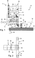
Fig. 1 eine Seitenansicht einer Ausführungsform einer Rollformvorrichtung, welche eine Mehrzahl von Walzenträgern umfasst; -
Fig. 2 eine Draufsicht eines der Walzenträger der Rollformvorrichtung gemäßFig. 1 ; -
Fig. 3 eine Draufsicht eines ersten Bewegungsübertragungselements des Walzenträgers gemäßFig. 2 ; -
Fig. 4 eine Draufsicht eines zweiten Bewegungsübertragungselements des Walzenträgers gemäßFig. 2 ; -
Fig. 5 eine Draufsicht der Rollformvorrichtung gemäßFig. 1 , wobei die Walzenträger zur Bearbeitung eines geradlinig begrenzten Walzmaterialbandes ausgerichtet sind; -
Fig. 6 eine derFig. 5 entsprechende Ansicht, wobei die Walzenträger zur Bearbeitung eines konisch begrenzten Walzmaterialbandes ausgerichtet sind; -
Fig. 7 eine derFig. 5 entsprechende Ansicht, wobei die Walzenträger zur Bearbeitung eines konvex begrenzten Walzmaterialbandes ausgerichtet sind; und -
Fig. 8 eine derFig. 5 entsprechende Ansicht, wobei die Walzenträger zur Bearbeitung eines konkav begrenzten Walzmaterialbandes ausgerichtet sind. - Eine Ausführungsform einer Rollformvorrichtung ist in der Zeichnung insgesamt mit dem Bezugszeichen 10 bezeichnet. Die Rollformvorrichtung 10 umfasst ein an einem aus Übersichtsgründen nicht dargestellten Gestell verschiebbar gelagerten Schwenkachsenträger 12, an welchem mindestens ein Walzenträger 14 schwenkbar gelagert ist. Der Walzenträger 14 dient zur Lagerung mindestens einer Walze 16, vorzugsweise eines Paars von Walzen 16 und 18, welche um jeweils zugeordnete Walzenachsen 20, 22 gegenläufig rotierend antreibbar sind.
- Die Walzen 16, 18 weisen jeweils eine Umfangsfläche auf, welche mit einem zu walzenden Walzmaterialband zusammenwirkt und daher als Wirkfläche 24, 26 bezeichnet ist.
- Der Schwenkachsenträger 12 und der Walzenträger 14 sind mittels eines Zustellantriebs 28 längs einer Zustellachse 30 in einer Richtung quer, insbesondere senkrecht, zu einer Vorschubrichtung 32 des Walzmaterialbandes 34 (vgl.
Figur 5 ) positionierbar. - Der Walzenträger 14 ist um eine Schwenkachse 36 relativ zu dem Schenkachsenträger 12 verschwenkbar. Die Schwenkachse 36 verläuft jeweils senkrecht zu der Zustellachse 30 und zu der Vorschubrichtung 32 des Walzmaterialbandes 34.
- Die Rollformvorrichtung 10 umfasst einen insgesamt mit dem Bezugszeichen 38 bezeichneten Drehantrieb, welche zum Drehantrieb der Walzen 16, 18 um die Walzenachsen 20, 22 dient.
- Der Drehantrieb 38 umfasst mindestens ein stationäres Antriebselement 40, welches eine Antriebsfläche 42 umfasst, die sich um eine Antriebselementachse 44 herum erstreckt. Bei dem Antriebselement 40 handelt es sich bspw. um ein sich längs der Achse 44 erstreckendes Zahnrad, dessen Zähne sich als Teil der Antriebsfläche 42 parallel zu der Achse 44 erstrecken.
- Das Antriebselement 40 ist ortsfest gelagert. Das Antriebselement 40 wirkt mit einem Getriebeteil 46 zusammen, welches bei einer Zustellung des Walzenträgers 14 entlang der Zustellachse 30 in der zu der Zustellachse 30 und zu der Antriebselementachse 44 paralleler Richtung verschoben wird. Auf diese Weise kann unabhängig von der Zustellposition des Walzenträgers 14 eine Drehbewegung des Antriebselements 40 auf das Getriebeteil 46 übertragen werden.
- Das Getriebeteil 46 wirkt über ein Winkelgetriebe 48 mit einer Antriebswelle 50 zusammen, deren Antriebswellenachse 52 zu der Schwenkachse 36 des Walzenträgers 14 koaxial verläuft.
- Die Antriebswelle 50 wirkt über ein weiteres Winkelgetriebe 54 mit einer Zusatzwelle 56 zusammen, welche drehbar an dem Walzenträger 14 gelagert ist. Eine Achse 58 der Zusatzwelle 56 verläuft parallel zu den Walzenachsen 20 und 22.
- Zur Übertragung der Drehbewegung der Zusatzwelle 56 auf die Walzen 16 und 18 ist ein insgesamt mit dem Bezugszeichen 60 bezeichnetes Stirnradgetriebe vorgesehen, sodass eine Drehbewegung der Zusatzwelle 56 gegenläufig zu einer Drehbewegung einer benachbarten Walzenwelle 62 der Walze 16 und gleichläufig zu einer Drehbewegung einer Walzenwelle 64 der Walze 18 ist.
- Die vorstehend beschriebenen Komponenten des Drehantriebs 38 sind entsprechend der Anzahl der Walzenträger der Rollformvorrichtung 10 mehrfach vorgesehen. Jedoch ist es möglich, einen gemeinsamen Drehantriebsmotor 66 vorzusehen, der bspw. über einen Riementrieb mehrere Antriebselemente 40 und somit die Walzen 16, 18 mehrerer Walzenträger gleichzeitig antreibt.
- Dem Walzenträger 14 sind zwei Bewegungsübertragungselemente 68, 70 zugeordnet (vgl.
Figuren 1, 2 ,3 und 4 ). Die Bewegungsübertragungselemente 68 und 70 sind jeweils um die Schwenkachse 36 des Walzenträgers 14 schwenkbar gelagert und weisen jeweils nach außen abragende Abschnitte 72, 74 auf, an welchen als Langloch ausgebildete Schwenkachsenaufnahmen 76, 78 vorgesehen sind. Die Schwenkachsenaufnahmen 76, 78 dienen zur Aufnahme von Schwenkachsen, welche zusätzlichen, zu dem Walzenträger 14 benachbarten, Walzenträgern zugeordnet sind. - Die Bewegungsübertragungselemente 68, 70 sind miteinander mittels eines Zwischengetriebes 80 bewegungsgekoppelt. Das Zwischengetriebe 80 umfasst ein um eine Getriebeachse 82 drehbares Getriebeelement 84, welches bspw. in Form eines Getrieberades 86 ausgebildet sind (vgl.
Figur 1 ). - Die Getriebeachse 82 ist an dem Walzenträger 14 gelagert und verläuft parallel zu den Walzenachsen 20, 22. Insbesondere erstrecken sich die Getriebeachse 82 und die Walzenachsen 20, 22 innerhalb einer gemeinsamen Ebene.
- Das Getrieberad 86 wirkt in Richtung der Schwenkachse 36 gesehen auf einander abgewandten Seiten mit jeweils einer gekrümmten Getriebebahn 88, 90 der Bewegungsübertragungselemente 68, 70 zusammen.
- Der Aufbau der Rollformvorrichtung 10 wird nachfolgend unter Bezugnahme auf
Figuren 5 bis 8 beschrieben. Die Rollformvorrichtung 10 weist einen zweiten Walzenträger 92 und einen dritten Walzenträger 94 auf. Der Aufbau der Walzenträger 92 und 94 ist zu dem vorstehend unter Bezugnahme auf den Walzenträger 14 beschriebenen Aufbau identisch. - Der zweite Walzenträger 92 ist mittels eines Zustellantriebs 96 längs einer Zustellachse 98 positionierbar und um eine Schwenkachse 100 verschwenkbar.
- Der dritte Walzenträger 94 ist mittels eines Zustellantriebs 102 längs einer Zustellachse 104 positionierbar und um eine Schwenkachse 106 verschwenkbar.
- Die Zustellachsen 30, 98, 104 verlaufen zueinander parallel. Die Schwenkachsen 36, 100, 106 verlaufen zueinander parallel.
- Die Zustellantriebe 28, 96, 102 sind unabhängig voneinander ansteuerbar, sodass den Walzenträgern 14, 92, 94 jeweils zugeordnete Schwenkachsenträger 12, 108, 110 und somit die Schwenkachsen 36, 100, 106 voneinander unabhängig längs der Zustellachsen 30, 98, 104 positionierbar sind.
- In
Figur 5 ist eine Ausgangslage der Rollformvorrichtung 10 dargestellt, bei welcher die Walzenträger 14, 92, 94 bezogen auf die Zustellachsen 30, 98, 104 identisch positioniert sind, sodass die jeweils einem Walzenträger 14, 92, 94 zugeordneten Walzen 16, 18 auf derselben Höhe angeordnet sind und zur Bearbeitung eines gradlinig begrenzten Walzmaterialbandes 34 geeignet sind. - Wenn ausgehend aus den in
Figur 5 dargestellten Positionen der Walzenträger 14, 92, 94 ein konisch begrenztes Walzmaterialband 34 bearbeitet werden soll, können bspw. die Zustellantriebe 96 und 102 so angesteuert werden, dass bezogen auf den ersten Walzenträger 14 der zweite Walzenträger 92 um einen Zustellweg nach vorne verschoben und der Walzenträger 94 um den doppelten Zustellweg verschoben wird. Diese Verschiebung der Walzenträger 92, 94 hat jedoch nicht nur eine Positionsänderung der Walzenträger 92 und 94 längs der Zustellachsen 98 und 104 zur Folge, sondern bewirkt (in Form einer "mechanischen Winkelberechnung") auch ein Verschwenken sämtlicher Walzenträger 14, 92, 94, und zwar eine gleichsinnige Verschwenkung um die jeweiligen Schwenkachsen 36, 100, 106, sodass die Walzen 16, 18 sämtlicher Walzenträger 14, 92, 94 zueinander parallel ausgerichtet sind (vgl.Fig. 6 ). - Die Schwenkbewegung der Walzenträger 14, 92, 94 wird bewirkt durch die jeweilige Bewegungskopplung der Walzenträger 14, 92, 94 untereinander mittels der Bewegungsübertragungselemente 68 und 70 und mittels des Zwischengetriebes 80. Bei einem gradlinig begrenzten Walzmaterialband 34 verbleiben die Bewegungsübertragungselemente 68, 70 in einer im Vergleich zu der Ausgangslage (vgl.
Figur 5 ) relativ zu dem jeweiligen Walzenträger 14, 92, 94 unverschwenkten Zustand. - Bei Bearbeitung eines gekrümmt begrenzten Walzmaterialbandes (bspw. konvex, vgl.
Figur 7 , oder konkav, vgl.Figur 8 ) werden die Bewegungsübertragungselemente 68, 70 eines Walzenträger (bspw. des Walzenträgers 92) relativ zu diesem verschwenkt. - Wenn bspw. äußere Walzenträger 14, 94 bezogen auf einen mittleren Walzenträger 92 entlang der jeweiligen Zustellachsen nach vorne positioniert werden (vgl.
Figur 7 ) werden dem mittleren Walzenträger 92 zugeordneten Bewegungsübertragungselemente 68 und 70 in entsprechender Weise nach vorne verschwenkt. Dabei wird (sofern die Vorschubbewegung der Walzenträger 14 und 92 identisch bemessen ist) mittels des Zwischengetriebes 80 des Walzenträger 92 erreicht, dass der Walzenträger 92 in einer unverschwenkten Lage verbleibt, in welcher die Walzen 16, 18 des mittleren Walzenträgers 92 tangential zu dem Walzmaterialband ausgerichtet sind. - Eine entsprechende Ausrichtung eines mittleren Walzenträgers 92 ergibt sich für ein konvex gekrümmtes Walzbandmaterial 34 (vgl.
Figur 8 ). Auch hierbei verbleibt der mittlere Walzenträger 92 in einer bezogen auf das Walzbandmaterial 34 tangentialen, unverschwenkten Ausgangslage, wenn die äußeren Walzenträger 14, 94 bezogen auf den mittleren Walzenträger 92 in identischer Richtung nach hinten positioniert werden. - Bei der Rollformvorrichtung 10 verlaufen gradlinige, gedachte Verlängerungen 112 (vgl.
Figur 1 ) der Schwenkachsen 36, 100, 106 jeweils durch die Wirkflächen 24, 26 der Walzen 16, 18 eines zugeordneten Walzenträgers 14, 92, 94. Die Rollformvorrichtung 10 ermöglicht einen Verzicht auf motorische Schwenkantriebe zum Schwenkantrieb der Walzenträger 14, 92, 94 um die jeweiligen Schwenkachsen 36, 100, 106. - Darüber hinaus ermöglicht es die beschriebene Konstruktion der Drehantriebseinrichtung 38, insbesondere die koaxiale Anordnung der Schwenkachsen 36, 100, 106 zu jeweiligen Antriebswellenachsen 52, dass ein gemeinsamer Drehantriebsmotor 66 ausreicht, um sämtliche Walzen 16, 18 aller Walzenträger 14, 92, 94 anzutreiben.
- Insgesamt kann im Vergleich zu herkömmlichen Rollformvorrichtungen die Anzahl der Antriebsmotoren erheblich reduziert werden. Hierdurch ist auch unter widrigen Bedingungen, insbesondere bei großer Hitze, ein besonders störungsarmer Betrieb der Rollformvorrichtung 10 möglich.
Claims (7)
- Rollformvorrichtung (10) zum Rollformen eines Walzmaterialbandes (34), umfassend mindestens einen um eine Schwenkachse schwenkbaren Walzenträger (14), an welchem mindestens eine Walze (16, 18) drehbar gelagert ist, wobei die Schwenkachse (36) des Walzenträgers (14) so angeordnet ist, dass sie in gedachter, gerader Verlängerung eine Wirkfläche (24, 26) der mindestens einen Walze (16, 18) durchdringt, dadurch gekennzeichnet, dass ein Drehantrieb (38) zum Drehen der mindestens einen Walze (16, 18) vorgesehen ist und dass eine Antriebswelle (50) des Drehantriebs (38) eine zu der Schwenkachse (36) koaxiale Antriebswellenachse (52) aufweist.
- Rollformvorrichtung (10) nach einem der voranstehenden Ansprüche, dadurch gekennzeichnet, dass der Drehantrieb (38) ein stationäres Antriebselement (40) mit einer Antriebsfläche (42) umfasst, welche sich um eine Antriebselementachse (44) herum erstreckt, dass die Antriebselementachse (44) und eine Zustellachse (30) des Walzenträgers (14) zueinander parallel sind und dass die Antriebsfläche (42) entlang der Antriebselementachse (44) gesehen so lang ist, dass entlang eines Zustellbereichs des Walzenträgers (14) ein an dem Walzenträger (14) gelagertes Getriebeteil (46) von dem Antriebselement (40) antreibbar ist.
- Rollformvorrichtung (10) nach einem der voranstehenden Ansprüche, wobei mindestens zwei in Vorschubrichtung (32) des Walzmaterialbandes (34) hintereinander angeordnete Walzenträger (14, 92) vorgesehen sind, dadurch gekennzeichnet, dass mindestens ein um die Schwenkachse (36) eines ersten Walzenträgers (14) verschwenkbares Bewegungsübertragungselement (68) vorgesehen ist, welches mit einer Schwenkachse (100) des zweiten Walzenträgers (92) bewegungsgekoppelt ist.
- Rollformvorrichtung (10) nach einem der voranstehenden Ansprüche, wobei mindestens drei in Vorschubrichtung (32) des Walzmaterialbandes (34) hintereinander angeordnete Walzenträger (14, 92, 94) vorgesehen sind, dadurch gekennzeichnet, dass mindestens zwei um die Schwenkachse (100) eines mittleren Walzenträgers (92) verschwenkbare Bewegungsübertragungselemente (68, 70) vorgesehen sind, welche jeweils mit einer der Schwenkachsen (36, 106) der bezogen auf den mittleren Walzenträger (92) äußeren Walzenträger (14,94) bewegungsgekoppelt sind.
- Rollformvorrichtung (10) nach Anspruch 4, dadurch gekennzeichnet, dass ein Zwischengetriebe (80) vorgesehen ist, mittels welchem die Bewegungsübertragungselemente (68, 70) untereinander bewegungsgekoppelt sind.
- Rollformvorrichtung (10) nach Anspruch 5, dadurch gekennzeichnet, dass das Zwischengetriebe (80) ein um eine Getriebeachse (82) drehbares Getriebeelement (84) umfasst, wobei die Getriebeachse (82) an dem mittleren Walzenträger (14) gelagert ist.
- Rollformvorrichtung (10) nach Anspruch 6, dadurch gekennzeichnet, dass das Getriebeelement (84) in Form eines Getrieberades (86) ausgebildet ist, welches auf voneinander abgewandten Seiten mit jeweils einem der Bewegungsübertragungselemente (68, 70) zusammenwirkt.
Applications Claiming Priority (2)
| Application Number | Priority Date | Filing Date | Title |
|---|---|---|---|
| DE201220003769 DE202012003769U1 (de) | 2012-04-16 | 2012-04-16 | Rollformvorrichtung zum Rollformen eines Walzmaterialbandes |
| PCT/EP2013/056356 WO2013156276A1 (de) | 2012-04-16 | 2013-03-26 | Rollformvorrichtung zum rollformen eines walzmaterialbandes |
Publications (2)
| Publication Number | Publication Date |
|---|---|
| EP2838677A1 EP2838677A1 (de) | 2015-02-25 |
| EP2838677B1 true EP2838677B1 (de) | 2017-03-08 |
Family
ID=47740470
Family Applications (1)
| Application Number | Title | Priority Date | Filing Date |
|---|---|---|---|
| EP13715921.6A Not-in-force EP2838677B1 (de) | 2012-04-16 | 2013-03-26 | Rollformvorrichtung zum rollformen eines walzmaterialbandes |
Country Status (3)
| Country | Link |
|---|---|
| EP (1) | EP2838677B1 (de) |
| DE (1) | DE202012003769U1 (de) |
| WO (1) | WO2013156276A1 (de) |
Family Cites Families (7)
| Publication number | Priority date | Publication date | Assignee | Title |
|---|---|---|---|---|
| US5722278A (en) * | 1993-09-21 | 1998-03-03 | Aisin Seiki Kabushiki Kaisha | Roll forming apparatus |
| DE102004036945B4 (de) | 2004-07-29 | 2007-05-24 | Nec Europe Ltd. | Verfahren zur Optimierung des Energieverbrauchs einer Station in einem Netzwerk |
| SE0500954L (sv) * | 2005-04-28 | 2006-02-14 | Ortic Ab | Produktionslinje och sätt att forma profiler |
| US7758089B2 (en) * | 2006-12-27 | 2010-07-20 | Sungwoo Hitech Co., Ltd. | Roll forming apparatus, method thereof, and bumper beam manufactured by the method |
| DE202010001152U1 (de) * | 2010-01-15 | 2011-05-26 | Weber, Axel, 72138 | Einrichtung zum Rollformprofilieren und Bombieren von Metallbandabschnitten |
| DE102010036945A1 (de) * | 2010-08-11 | 2012-02-16 | Data M Sheet Metal Solutions Gmbh | Verfahren zur Erzeugung von optimierten, krümmungsstetigen 2D- bzw. 3D-Walzprofilverläufen und entsprechende Vorrichtung |
| SE1001228A1 (sv) * | 2010-12-28 | 2012-03-20 | Ortic 3D Ab | Rullformningsmaskin och sätt att rullforma ett plant ämne med variabel bredd |
-
2012
- 2012-04-16 DE DE201220003769 patent/DE202012003769U1/de not_active Expired - Lifetime
-
2013
- 2013-03-26 WO PCT/EP2013/056356 patent/WO2013156276A1/de not_active Ceased
- 2013-03-26 EP EP13715921.6A patent/EP2838677B1/de not_active Not-in-force
Also Published As
| Publication number | Publication date |
|---|---|
| DE202012003769U1 (de) | 2013-01-22 |
| WO2013156276A1 (de) | 2013-10-24 |
| EP2838677A1 (de) | 2015-02-25 |
Similar Documents
| Publication | Publication Date | Title |
|---|---|---|
| EP0170773B1 (de) | Zahnstangentrieb für die Erzeugung einer Relativbewegung zwischen zwei aneinandergeführten Maschinenteilen | |
| DE69823840T2 (de) | Lenkgetriebe für drehbare räder an einem fahrzeug | |
| EP3033187B1 (de) | Transfervorrichtung für ein werkstück | |
| DE102014202729B4 (de) | Stanznietvorrichtung mit weiterschaltenden matrizen | |
| EP2415675B1 (de) | Vorrichtung zum Fördern von Gegenständen in Verpackungsmaschinen | |
| EP3398754B1 (de) | Antriebsanordnung für schweissautomaten | |
| DE4036341A1 (de) | Gruppiereinrichtung | |
| DE2611820A1 (de) | Insbesondere in verbindung mit rotations-schnelldruck-pressen verwendbare faltvorrichtung | |
| DE2821650C2 (de) | Vorrichtung zum Öffnen oder Ausbreiten einer im Strang behandelten Textilbahn | |
| DE3736002C2 (de) | ||
| DE2523831A1 (de) | Maschine zum richten von draehten | |
| DE102012201915B3 (de) | Längsförderer für stabförmige Produkte der Tabak verarbeitenden Industrie und Fördereinrichtung mit einem Längsförderer und Verfahren zum Betreiben eines Längsförderers | |
| EP0354515B1 (de) | Längsschneide- oder Rillmaschine für eine bewegte Wellpappenbahn | |
| EP3150291B1 (de) | Verfahren und vorrichtung zum kühlen einer in einem walzgerüst angeordneten walze | |
| EP1772401A1 (de) | Ausschleusvorrichtung | |
| EP3319846A1 (de) | Waschvorrichtung für eine fahrzeugwaschanlage und fahrzeugwaschanlage | |
| DE3001271A1 (de) | Zufuehrungseinrichtung vom walzentyp zum zufuehren von flaechigem material | |
| EP3556667B1 (de) | Umreifungsvorrichtung | |
| WO2019057577A1 (de) | Ofenrolle, transportvorrichtung hiermit und verfahren zu deren betrieb | |
| DE69716975T2 (de) | Handhabungseinrichtung für Produkte | |
| EP2838677A1 (de) | Rollformvorrichtung zum rollformen eines walzmaterialbandes | |
| DE102021125587B3 (de) | Vorrichtung und Verfahren zum Ausrichten von Würsten | |
| DE2420584C3 (de) | Wickelmaschine für Bandmaterial o.dgl. | |
| DE2115115C3 (de) | Typenwählvorrichtung für einen Drucker | |
| DE29613831U1 (de) | Vorrichtung zum beidseitigen Beschleifen mit einer Ausrichtvorrichtung |
Legal Events
| Date | Code | Title | Description |
|---|---|---|---|
| PUAI | Public reference made under article 153(3) epc to a published international application that has entered the european phase |
Free format text: ORIGINAL CODE: 0009012 |
|
| 17P | Request for examination filed |
Effective date: 20141031 |
|
| AK | Designated contracting states |
Kind code of ref document: A1 Designated state(s): AL AT BE BG CH CY CZ DE DK EE ES FI FR GB GR HR HU IE IS IT LI LT LU LV MC MK MT NL NO PL PT RO RS SE SI SK SM TR |
|
| AX | Request for extension of the european patent |
Extension state: BA ME |
|
| DAX | Request for extension of the european patent (deleted) | ||
| GRAP | Despatch of communication of intention to grant a patent |
Free format text: ORIGINAL CODE: EPIDOSNIGR1 |
|
| INTG | Intention to grant announced |
Effective date: 20160919 |
|
| GRAS | Grant fee paid |
Free format text: ORIGINAL CODE: EPIDOSNIGR3 |
|
| GRAA | (expected) grant |
Free format text: ORIGINAL CODE: 0009210 |
|
| AK | Designated contracting states |
Kind code of ref document: B1 Designated state(s): AL AT BE BG CH CY CZ DE DK EE ES FI FR GB GR HR HU IE IS IT LI LT LU LV MC MK MT NL NO PL PT RO RS SE SI SK SM TR |
|
| REG | Reference to a national code |
Ref country code: GB Ref legal event code: FG4D Free format text: NOT ENGLISH |
|
| REG | Reference to a national code |
Ref country code: CH Ref legal event code: EP Ref country code: AT Ref legal event code: REF Ref document number: 873066 Country of ref document: AT Kind code of ref document: T Effective date: 20170315 |
|
| REG | Reference to a national code |
Ref country code: IE Ref legal event code: FG4D Free format text: LANGUAGE OF EP DOCUMENT: GERMAN |
|
| REG | Reference to a national code |
Ref country code: DE Ref legal event code: R096 Ref document number: 502013006596 Country of ref document: DE |
|
| REG | Reference to a national code |
Ref country code: LT Ref legal event code: MG4D |
|
| REG | Reference to a national code |
Ref country code: NL Ref legal event code: MP Effective date: 20170308 |
|
| PG25 | Lapsed in a contracting state [announced via postgrant information from national office to epo] |
Ref country code: GR Free format text: LAPSE BECAUSE OF FAILURE TO SUBMIT A TRANSLATION OF THE DESCRIPTION OR TO PAY THE FEE WITHIN THE PRESCRIBED TIME-LIMIT Effective date: 20170609 Ref country code: LT Free format text: LAPSE BECAUSE OF FAILURE TO SUBMIT A TRANSLATION OF THE DESCRIPTION OR TO PAY THE FEE WITHIN THE PRESCRIBED TIME-LIMIT Effective date: 20170308 Ref country code: NO Free format text: LAPSE BECAUSE OF FAILURE TO SUBMIT A TRANSLATION OF THE DESCRIPTION OR TO PAY THE FEE WITHIN THE PRESCRIBED TIME-LIMIT Effective date: 20170608 Ref country code: HR Free format text: LAPSE BECAUSE OF FAILURE TO SUBMIT A TRANSLATION OF THE DESCRIPTION OR TO PAY THE FEE WITHIN THE PRESCRIBED TIME-LIMIT Effective date: 20170308 Ref country code: FI Free format text: LAPSE BECAUSE OF FAILURE TO SUBMIT A TRANSLATION OF THE DESCRIPTION OR TO PAY THE FEE WITHIN THE PRESCRIBED TIME-LIMIT Effective date: 20170308 |
|
| PG25 | Lapsed in a contracting state [announced via postgrant information from national office to epo] |
Ref country code: LV Free format text: LAPSE BECAUSE OF FAILURE TO SUBMIT A TRANSLATION OF THE DESCRIPTION OR TO PAY THE FEE WITHIN THE PRESCRIBED TIME-LIMIT Effective date: 20170308 Ref country code: RS Free format text: LAPSE BECAUSE OF FAILURE TO SUBMIT A TRANSLATION OF THE DESCRIPTION OR TO PAY THE FEE WITHIN THE PRESCRIBED TIME-LIMIT Effective date: 20170308 Ref country code: BG Free format text: LAPSE BECAUSE OF FAILURE TO SUBMIT A TRANSLATION OF THE DESCRIPTION OR TO PAY THE FEE WITHIN THE PRESCRIBED TIME-LIMIT Effective date: 20170608 Ref country code: SE Free format text: LAPSE BECAUSE OF FAILURE TO SUBMIT A TRANSLATION OF THE DESCRIPTION OR TO PAY THE FEE WITHIN THE PRESCRIBED TIME-LIMIT Effective date: 20170308 Ref country code: ES Free format text: LAPSE BECAUSE OF FAILURE TO SUBMIT A TRANSLATION OF THE DESCRIPTION OR TO PAY THE FEE WITHIN THE PRESCRIBED TIME-LIMIT Effective date: 20170308 |
|
| PG25 | Lapsed in a contracting state [announced via postgrant information from national office to epo] |
Ref country code: NL Free format text: LAPSE BECAUSE OF FAILURE TO SUBMIT A TRANSLATION OF THE DESCRIPTION OR TO PAY THE FEE WITHIN THE PRESCRIBED TIME-LIMIT Effective date: 20170308 |
|
| PG25 | Lapsed in a contracting state [announced via postgrant information from national office to epo] |
Ref country code: CZ Free format text: LAPSE BECAUSE OF FAILURE TO SUBMIT A TRANSLATION OF THE DESCRIPTION OR TO PAY THE FEE WITHIN THE PRESCRIBED TIME-LIMIT Effective date: 20170308 Ref country code: RO Free format text: LAPSE BECAUSE OF FAILURE TO SUBMIT A TRANSLATION OF THE DESCRIPTION OR TO PAY THE FEE WITHIN THE PRESCRIBED TIME-LIMIT Effective date: 20170308 Ref country code: SK Free format text: LAPSE BECAUSE OF FAILURE TO SUBMIT A TRANSLATION OF THE DESCRIPTION OR TO PAY THE FEE WITHIN THE PRESCRIBED TIME-LIMIT Effective date: 20170308 Ref country code: IT Free format text: LAPSE BECAUSE OF FAILURE TO SUBMIT A TRANSLATION OF THE DESCRIPTION OR TO PAY THE FEE WITHIN THE PRESCRIBED TIME-LIMIT Effective date: 20170308 Ref country code: EE Free format text: LAPSE BECAUSE OF FAILURE TO SUBMIT A TRANSLATION OF THE DESCRIPTION OR TO PAY THE FEE WITHIN THE PRESCRIBED TIME-LIMIT Effective date: 20170308 |
|
| REG | Reference to a national code |
Ref country code: CH Ref legal event code: PL |
|
| PG25 | Lapsed in a contracting state [announced via postgrant information from national office to epo] |
Ref country code: IS Free format text: LAPSE BECAUSE OF FAILURE TO SUBMIT A TRANSLATION OF THE DESCRIPTION OR TO PAY THE FEE WITHIN THE PRESCRIBED TIME-LIMIT Effective date: 20170708 Ref country code: SM Free format text: LAPSE BECAUSE OF FAILURE TO SUBMIT A TRANSLATION OF THE DESCRIPTION OR TO PAY THE FEE WITHIN THE PRESCRIBED TIME-LIMIT Effective date: 20170308 Ref country code: PL Free format text: LAPSE BECAUSE OF FAILURE TO SUBMIT A TRANSLATION OF THE DESCRIPTION OR TO PAY THE FEE WITHIN THE PRESCRIBED TIME-LIMIT Effective date: 20170308 Ref country code: PT Free format text: LAPSE BECAUSE OF FAILURE TO SUBMIT A TRANSLATION OF THE DESCRIPTION OR TO PAY THE FEE WITHIN THE PRESCRIBED TIME-LIMIT Effective date: 20170710 |
|
| REG | Reference to a national code |
Ref country code: DE Ref legal event code: R097 Ref document number: 502013006596 Country of ref document: DE |
|
| REG | Reference to a national code |
Ref country code: IE Ref legal event code: MM4A |
|
| PLBE | No opposition filed within time limit |
Free format text: ORIGINAL CODE: 0009261 |
|
| STAA | Information on the status of an ep patent application or granted ep patent |
Free format text: STATUS: NO OPPOSITION FILED WITHIN TIME LIMIT |
|
| PG25 | Lapsed in a contracting state [announced via postgrant information from national office to epo] |
Ref country code: MC Free format text: LAPSE BECAUSE OF FAILURE TO SUBMIT A TRANSLATION OF THE DESCRIPTION OR TO PAY THE FEE WITHIN THE PRESCRIBED TIME-LIMIT Effective date: 20170308 Ref country code: DK Free format text: LAPSE BECAUSE OF FAILURE TO SUBMIT A TRANSLATION OF THE DESCRIPTION OR TO PAY THE FEE WITHIN THE PRESCRIBED TIME-LIMIT Effective date: 20170308 Ref country code: LU Free format text: LAPSE BECAUSE OF NON-PAYMENT OF DUE FEES Effective date: 20170326 |
|
| REG | Reference to a national code |
Ref country code: FR Ref legal event code: ST Effective date: 20171229 |
|
| 26N | No opposition filed |
Effective date: 20171211 |
|
| GBPC | Gb: european patent ceased through non-payment of renewal fee |
Effective date: 20170608 |
|
| PG25 | Lapsed in a contracting state [announced via postgrant information from national office to epo] |
Ref country code: SI Free format text: LAPSE BECAUSE OF FAILURE TO SUBMIT A TRANSLATION OF THE DESCRIPTION OR TO PAY THE FEE WITHIN THE PRESCRIBED TIME-LIMIT Effective date: 20170308 Ref country code: CH Free format text: LAPSE BECAUSE OF NON-PAYMENT OF DUE FEES Effective date: 20170331 Ref country code: IE Free format text: LAPSE BECAUSE OF NON-PAYMENT OF DUE FEES Effective date: 20170326 Ref country code: LI Free format text: LAPSE BECAUSE OF NON-PAYMENT OF DUE FEES Effective date: 20170331 |
|
| REG | Reference to a national code |
Ref country code: BE Ref legal event code: MM Effective date: 20170331 |
|
| PG25 | Lapsed in a contracting state [announced via postgrant information from national office to epo] |
Ref country code: GB Free format text: LAPSE BECAUSE OF NON-PAYMENT OF DUE FEES Effective date: 20170608 |
|
| PG25 | Lapsed in a contracting state [announced via postgrant information from national office to epo] |
Ref country code: BE Free format text: LAPSE BECAUSE OF NON-PAYMENT OF DUE FEES Effective date: 20170331 Ref country code: FR Free format text: LAPSE BECAUSE OF NON-PAYMENT OF DUE FEES Effective date: 20170509 |
|
| PG25 | Lapsed in a contracting state [announced via postgrant information from national office to epo] |
Ref country code: MT Free format text: LAPSE BECAUSE OF FAILURE TO SUBMIT A TRANSLATION OF THE DESCRIPTION OR TO PAY THE FEE WITHIN THE PRESCRIBED TIME-LIMIT Effective date: 20170308 |
|
| PGFP | Annual fee paid to national office [announced via postgrant information from national office to epo] |
Ref country code: DE Payment date: 20180924 Year of fee payment: 6 |
|
| REG | Reference to a national code |
Ref country code: AT Ref legal event code: MM01 Ref document number: 873066 Country of ref document: AT Kind code of ref document: T Effective date: 20180326 |
|
| PG25 | Lapsed in a contracting state [announced via postgrant information from national office to epo] |
Ref country code: HU Free format text: LAPSE BECAUSE OF FAILURE TO SUBMIT A TRANSLATION OF THE DESCRIPTION OR TO PAY THE FEE WITHIN THE PRESCRIBED TIME-LIMIT; INVALID AB INITIO Effective date: 20130326 |
|
| REG | Reference to a national code |
Ref country code: DE Ref legal event code: R119 Ref document number: 502013006596 Country of ref document: DE |
|
| PG25 | Lapsed in a contracting state [announced via postgrant information from national office to epo] |
Ref country code: CY Free format text: LAPSE BECAUSE OF FAILURE TO SUBMIT A TRANSLATION OF THE DESCRIPTION OR TO PAY THE FEE WITHIN THE PRESCRIBED TIME-LIMIT Effective date: 20170308 Ref country code: AT Free format text: LAPSE BECAUSE OF NON-PAYMENT OF DUE FEES Effective date: 20180326 |
|
| PG25 | Lapsed in a contracting state [announced via postgrant information from national office to epo] |
Ref country code: MK Free format text: LAPSE BECAUSE OF FAILURE TO SUBMIT A TRANSLATION OF THE DESCRIPTION OR TO PAY THE FEE WITHIN THE PRESCRIBED TIME-LIMIT Effective date: 20170308 |
|
| PG25 | Lapsed in a contracting state [announced via postgrant information from national office to epo] |
Ref country code: DE Free format text: LAPSE BECAUSE OF NON-PAYMENT OF DUE FEES Effective date: 20191001 |
|
| PG25 | Lapsed in a contracting state [announced via postgrant information from national office to epo] |
Ref country code: TR Free format text: LAPSE BECAUSE OF FAILURE TO SUBMIT A TRANSLATION OF THE DESCRIPTION OR TO PAY THE FEE WITHIN THE PRESCRIBED TIME-LIMIT Effective date: 20170308 |
|
| PG25 | Lapsed in a contracting state [announced via postgrant information from national office to epo] |
Ref country code: AL Free format text: LAPSE BECAUSE OF FAILURE TO SUBMIT A TRANSLATION OF THE DESCRIPTION OR TO PAY THE FEE WITHIN THE PRESCRIBED TIME-LIMIT Effective date: 20170308 |