EP2838456B1 - Spinous process fixation apparatus - Google Patents
Spinous process fixation apparatus Download PDFInfo
- Publication number
- EP2838456B1 EP2838456B1 EP13778931.9A EP13778931A EP2838456B1 EP 2838456 B1 EP2838456 B1 EP 2838456B1 EP 13778931 A EP13778931 A EP 13778931A EP 2838456 B1 EP2838456 B1 EP 2838456B1
- Authority
- EP
- European Patent Office
- Prior art keywords
- plate
- implantable device
- plates
- post
- implant
- Prior art date
- Legal status (The legal status is an assumption and is not a legal conclusion. Google has not performed a legal analysis and makes no representation as to the accuracy of the status listed.)
- Active
Links
Images


Classifications
-
- A—HUMAN NECESSITIES
- A61—MEDICAL OR VETERINARY SCIENCE; HYGIENE
- A61B—DIAGNOSIS; SURGERY; IDENTIFICATION
- A61B17/00—Surgical instruments, devices or methods
- A61B17/56—Surgical instruments or methods for treatment of bones or joints; Devices specially adapted therefor
- A61B17/58—Surgical instruments or methods for treatment of bones or joints; Devices specially adapted therefor for osteosynthesis, e.g. bone plates, screws or setting implements
- A61B17/68—Internal fixation devices, including fasteners and spinal fixators, even if a part thereof projects from the skin
- A61B17/70—Spinal positioners or stabilisers, e.g. stabilisers comprising fluid filler in an implant
- A61B17/7062—Devices acting on, attached to, or simulating the effect of, vertebral processes, vertebral facets or ribs ; Tools for such devices
- A61B17/7068—Devices comprising separate rigid parts, assembled in situ, to bear on each side of spinous processes; Tools therefor
Definitions
- This invention relates generally to spinal surgery, and more particularly to devices for stabilization of the spine in association with placement of an interbody construct for interbody fusion or the like.
- interbody fusion devices are widely used following partial or total discectomies for stabilization of the spine at the site.
- Some stabilization devices are anchored to the pedicles.
- the use of the pedicles requires screws or other anchoring devices that occupy significant space and involve muscle dissection and associated work-time for implantation. Nerve root injuries are a well-known potential complication of placement of screws in the pedicles.
- the interspinous process devices are designed to increase the interspinous process height, thereby increasing the sagittal cross-sectional area of the foramen, where the nerve roots pass away out of the spine. It is thought that these devices may also unload the facet joints, and perhaps the intervertebral disc. They may limit spinal extension. This backward bending position may be painful for patients with spinal stenosis because it reduces the space available for the nerve roots in the exiting foraminal openings.
- interspinous process fixation devices are also common to fix adjacent spinous processes to each other to stabilize the spinal motion-segment as an adjunct to spinal fusion.
- Current systems include spinous process plates that are fixed with adjacent spinous processes sandwiched therebetween.
- a interspinous spacer assembly for insertion and/or implantation between spinous processes of adjacent superior and inferior vertebrae includes an interspinous spacer member sized and configured for insertion into the interspinous space located between adjacent spinous processes and an engagement mechanism for operatively coupling the spacer member to the adjacent spinous processes and for preventing migration of the assembly once implanted.
- the interspinous spacer assembly is adjustable to conform to the individual anatomy of a patient's spine.
- US 2010/087869 A1 describes methods and devices which are configured to attach an orthopedic implant onto a first vertebral bone of a functional spinal unit.
- a segment of the implant forms an abutment surface with a segment of a second vertebral bone within an unstable, or potentially unstable, vertebral column wherein the abutment surface resists and opposes aberrant movement between the first and second vertebral bones within a horizontal plane.
- the device may be rigidly attached onto the first vertebral bone but movable relative to the second vertebral bone.
- the invention is described in claim 1. Preferred embodiments of the invention are described in the sub claims.
- an implantable device for fixation of spinous processes The device comprises first and second spaced plates configured for attachment to portions of adjacent spinous processes.
- Ranges can be expressed herein as from “about” one particular value, and/or to "about” another particular value. When such a range is expressed, another aspect includes from the one particular value and/or to the other particular value. Similarly, when values are expressed as approximations, by use of the antecedent "about,” it will be understood that the particular value forms another aspect. It will be further understood that the endpoints of each of the ranges are significant both in relation to the other endpoint, and independently of the other endpoint.
- the terms "optional” or “optionally” mean that the subsequently described event or circumstance may or may not occur, and that the description includes instances where said event or circumstance occurs and instances where it does not.
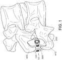
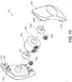
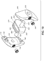
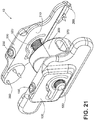
- an implantable device 10 for fixation of spinous processes comprising first and second spaced plates 100, 200 configured for attachment to portions of adjacent spinous processes.
- each plate has a first and second surface, whereby the first surface 110 of the first plate 100 is configured to face the second surface 210 of the second plate 200.
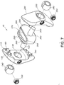
- the device comprises an implant 300 with a first face 310, an opposed second face 320, a top portion 330, and a bottom portion 340.
- the implant 300 is configured for insertion between two adjacent spinous processes.
- the implant is an interbody cage.
- the first face 310 of the implant faces the first surface 110 of the first plate 100 and the second face 320 of the implant faces the second surface of the second plate 200.
- the first plate is connected to a portion of the implant substantially adjacent the first face
- the second plate is connected to a portion of the implant 300 substantially adjacent the second face.
- the plates can be able to move with respect to the implant in order to adjust to the contour of the portions of the spinous processes onto which they attach.
- the plates can move polyaxially with respect to the implant.
- one or both of the first and second plates are pivotally connected to the respective portions of the implant. As such, there exist several options to accomplish this feature.
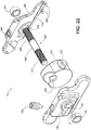
- the implant comprises a first post 120 projecting therefrom the first face and a second post 220 projecting therefrom the second face.
- the first and second posts are substantially normal to the respective first and second faces.
- the first and second post can be positioned at an acute angle relative to the respective first and second faces of the implant 300.
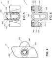
- the first plate comprises a first socket 130 for complimentary receipt of the first post 120 and the second plate 200 comprises a second socket 230 for complimentary receipt of the second post 220.
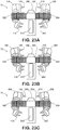
- a first internal collar 140 can be positioned within the first socket 130 and a second internal collar 240 can be positioned within the second socket 230.
- the collars thus, can be configured to engage a portion of the respective first and second posts.
- each internal collar can be configured to pivot within each respective socket, thereby permitting polyaxial movement of the first and second plates with respect to the implant.
- the collars can have an external diameter that is larger than the diameter of the socket, thereby resisting movement of the collars into or out of the socket. Additionally, the collars may comprise a slit, which can be compressed for insertion into each socket during manufacturing.
- there can be set screws 150, 250 configured to interface with each collar to tighten the collars thereto the respective first and second posts.
- the collars are configured to interface at a desired connection point along the particular post with which it interfaces, thereby selectively controlling the distance between the first and second surface of the first and second plates, respectively.
- the posts may comprise flexible material, thereby permitting polyaxial movement of the first and second plates with respect to the implant.
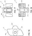
- the plates can be connected thereto the posts without the use of collars, as shown in FIGs. 14-19 .
- the posts can project therefrom the first and second surfaces of the first and second plates, respectively, rather than from the first and second faces 310, 320 of the implant.
- the first and second posts are substantially normal to the respective first and second surfaces.
- the implant comprises a first socket for complimentary receipt of the first post and a second socket 230 for complimentary receipt of the second post.
- a first internal collar 140 is positioned within the first socket 130 and a second internal collar 240 is positioned within the second socket.
- the first and second collars are configured to engage a portion of the respective first and second posts 120, 220. In one aspect, they can engage the posts along the length of the post, thereby allowing for variance in the distance between the two plates.
- each internal collar can pivot within each respective socket, thereby permitting polyaxial movement of the first and second plates with respect to the implant 300.
- first post and the second post are flexible, thereby permitting polyaxial movement of the first and second plates with respect to the implant.
- At least one of the first and second surfaces 110, 210 of the plates 100, 200 comprises teeth 160, 260 for frictional engagement of spinous processes.
- both the first and second surfaces can comprise teeth.
- the teeth 160, 260 for example, engage the spinous processes when the plates are clamped thereon.
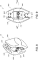
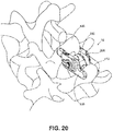
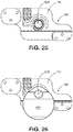
- the top portion 330 of the implant defines a longitudinal trough 350 configured for complimentary receipt of a portion of a first spinous process 400.
- the bottom portion 340 of the implant may likewise define a longitudinal trough 350 configured for complimentary receipt of a second spinous process 410, which would be adjacent the first spinous process 400.
- the longitudinal trough of the top portion can also comprise external edges that have a plurality of consecutive ridges 360 configured for frictional engagement with a portion of the first spinous process.
- the longitudinal trough of the bottom portion may also have external edges with pluralities of consecutive ridges 360 for frictional engagement with a portion of the second spinous process 410.
- the implant can also comprise a tapered distal nose, as illustrated in FIG. 7 .
- the implant 300 defines an internal cavity 370 in communication with at least one of the top portion and the bottom portion.
- the internal cavity 370 is in communication with both the top portion and the bottom portion.
- the professional may introduce bone cement or bone graft material into the internal cavity to assist in fusion or bonding of the implant with the surrounding spinous processes.
- the method comprises assembling the components of the implantable device into an implant assembly (i.e. the first and second plates, and the implant), exposing at least one desired spinous process, inserting the implant 300 between two adjacent spinous processes, joining the first and second plates to the implant with a portion of the spinous processes being positioned therebetween, compressing the plates onto the first and second spinous processes, and maintaining the compression of the plates while affixing the plates with respect to the implant.
- an implant assembly i.e. the first and second plates, and the implant
- exposing at least one desired spinous process inserting the implant 300 between two adjacent spinous processes, joining the first and second plates to the implant with a portion of the spinous processes being positioned therebetween, compressing the plates onto the first and second spinous processes, and maintaining the compression of the plates while affixing the plates with respect to the implant.
- the implant can comprise a first and second post extended therefrom the first and second faces of the implant 300, each post configured for engagement with the first and second plates.
- the step of joining the first and second plates with the implant can comprise sliding the first plate 100 onto the first post 120 and the second plate 200 onto the second post whereby portions of the first and second spinous processes are positioned in a space between the first and second surfaces and affixing the first plate to the first post and the second plate to the second post.
- the first and second plates comprise collars with set screws
- affixing the first and second plates onto the first and second posts can comprise merely tightening the set screws.
- the method comprises the step of angulating one or both of the first and second plates relative to each other in at least one plane during compression on the spinous process.
- the method comprises angulating the two plates in two planes during compression of the plates onto the spinous processes.
- the two planes are the coronal and axial planes.
- the implant defines an internal cavity in communication with its top and bottom portions.
- the method further comprises introducing bone graft material into the internal cavity, where the material is selected from the group consisting of autologous bone, allograft bone, bone substitute, and osteoinductive agent.
- the method comprises introducing bone cement into the internal cavity.
- the implantable device can comprise two spaced plates connected via a single post 520.
- an implant may or may not be present.
- the implantable device comprises first and second spaced plates 100, 200, the first plate 100 having a first surface 110 facing a second surface 210 of the second plate 200.
- the post 520 is connectable to the first and second plates.
- the post in this aspect, has a first end portion 522, a second end portion 524, and a middle portion 526, where the first plate 100 is configured to connect to the first end portion 522 of the post 520 and the second plate 200 is configured to connect to the second end portion 524 of the post.
- the implantable device is configured for polyaxial movement of the first and second plates with respect to at least portions of the post 520 when the first and second plates are connected to the post.
- the first and/or second plate can be configured to pivotally connect to a portion of the respective end portion of the post.
- the first and second plates can be configured to connect to the post at a first and second connection point 530, 532, respectively.
- the connection points can be adjustable to control the distance between the first and second surfaces.
- the polyaxial movement of the plates with respect to the post can be accomplished in the various manners described herein above.
- an implant 300 such as the ones described herein, can be positioned therebetween the first and second spaced place.
- at least a portion of the post is configured to pass therethrough a portion of the implant.
- the implant defines an aperture 380 through which the post can pass.
- the implant may also define an internal cavity (graft window) 370 for introduction of bone cement or bone graft material into the internal cavity to assist in fusion or bonding of the implant with the surrounding spinous processes.
- the implantable device leads to a method of fixation of spinous processes of a subject.
- the method comprises assembling components into the described implant assembly, exposing a desired spinous process, connecting the first plate 100 to a portion of the first end portion 522 of the post, inserting the middle portion 526 of the post between adjacent spinous processes to position the post substantially between a first spinous process and a second spinous process, sliding the second plate 200 onto a portion of the second end portion 524 of the post 520 whereby portions of the first and second spinous processes are positioned in a space between the first and second surfaces, compressing the plates onto the first and second spinous processes; and maintaining compression of the plates onto the first and second spinous processes while affixing the first plate to the first end portion and the second plate to the second end portion.
- This aspect of the method can also comprise angulating the first plate relative to the second plate in at least one plane during compression of the plates on the spinous processes.
- the step of angulating the first plate relative to the second plate comprises angulating the two plates in two planes during compression of the plates onto the spinous processes.
- the angulation of the first plate relative to the second plate is in coronal and axial planes.
- the method can also comprise means for pivotally connecting the first and second end portions, respectively.
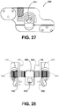
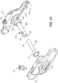
- the implantable device can comprise the first and second spaced plates 100, 200 with a first post 120 having a first end 122 pivotally connected to the first surface 110 of the first plate 100 and a second end 124 spaced therefrom the first surface, as well as a second post 220 having a second end 222 pivotally connected to the second surface 210 of the second plate 200 and a first end 224 spaced therefrom the second surface.
- the second post is at least partially tubular, defining an interior longitudinal cavity 226. Additionally, in this aspect, at least a portion of the first post is configured to be telescopingly received by the interior longitudinal cavity.
- the position of the first post relative to the second post can be fixed using a set screw 228 positioned through a portion of the second post configured to engage the first post and maintain its position.
- the position may also be fixed using a collar or band around a portion of the second post that tightens in any known fashion.
- the second post may also be crimped onto the first post. Other known fixation means can also be employed.
- an implant can be positioned therebetween the first and second spaced plates.
- at least a portion of at least one of the first and second posts is configured to pass therethrough a portion of the implant.
- the first plate 100 comprises a first socket 130 for complimentary receipt of the first end 122 of the first post 120
- the second plate 200 comprises a second socket 230 for complimentary receipt of the second end 222 of the second post 220.
- the first collar is configured to engage a portion of the first end of the first post and the second collar is configured to engage a portion of the second end of the second post.
- each internal collar is configured to pivot within each respective socket, thereby permitting the polyaxial movement of the first and second plates with respect to the first and second posts, respectively.
- a first set screw can also be configured to interface with the first collar, and a second set screw can be configured to interface with the second collar to tighten the collars thereto the respective first and second posts.
- the first and second posts can be substantially flexible, thereby permitting the polyaxial movement of the first and second plates with respect to the respective first and second post.
Landscapes
- Health & Medical Sciences (AREA)
- Orthopedic Medicine & Surgery (AREA)
- Life Sciences & Earth Sciences (AREA)
- Neurology (AREA)
- Surgery (AREA)
- Heart & Thoracic Surgery (AREA)
- Engineering & Computer Science (AREA)
- Biomedical Technology (AREA)
- Nuclear Medicine, Radiotherapy & Molecular Imaging (AREA)
- Medical Informatics (AREA)
- Molecular Biology (AREA)
- Animal Behavior & Ethology (AREA)
- General Health & Medical Sciences (AREA)
- Public Health (AREA)
- Veterinary Medicine (AREA)
- Prostheses (AREA)
- Surgical Instruments (AREA)
Applications Claiming Priority (2)
| Application Number | Priority Date | Filing Date | Title |
|---|---|---|---|
| US13/452,587 US8603143B2 (en) | 2010-12-05 | 2012-04-20 | Spinous process fixation apparatus |
| PCT/US2013/037602 WO2013159097A1 (en) | 2012-04-20 | 2013-04-22 | Spinous process fixation apparatus and method |
Publications (3)
| Publication Number | Publication Date |
|---|---|
| EP2838456A1 EP2838456A1 (en) | 2015-02-25 |
| EP2838456A4 EP2838456A4 (en) | 2016-01-06 |
| EP2838456B1 true EP2838456B1 (en) | 2020-11-11 |
Family
ID=49384143
Family Applications (1)
| Application Number | Title | Priority Date | Filing Date |
|---|---|---|---|
| EP13778931.9A Active EP2838456B1 (en) | 2012-04-20 | 2013-04-22 | Spinous process fixation apparatus |
Country Status (8)
Families Citing this family (3)
| Publication number | Priority date | Publication date | Assignee | Title |
|---|---|---|---|---|
| WO2008106140A2 (en) | 2007-02-26 | 2008-09-04 | Abdou M Samy | Spinal stabilization systems and methods of use |
| US10335207B2 (en) | 2015-12-29 | 2019-07-02 | Nuvasive, Inc. | Spinous process plate fixation assembly |
| CN106264695B (zh) * | 2016-08-01 | 2018-12-18 | 周建明 | 腰椎用棘突间撑开装置 |
Citations (1)
| Publication number | Priority date | Publication date | Assignee | Title |
|---|---|---|---|---|
| WO2012078174A1 (en) * | 2010-12-05 | 2012-06-14 | Robinson James C | Spinous process fixation apparatus and method |
Family Cites Families (11)
| Publication number | Priority date | Publication date | Assignee | Title |
|---|---|---|---|---|
| US7048736B2 (en) * | 2002-05-17 | 2006-05-23 | Sdgi Holdings, Inc. | Device for fixation of spinous processes |
| US7699873B2 (en) * | 2005-11-23 | 2010-04-20 | Warsaw Orthopedic, Inc. | Spinous process anchoring systems and methods |
| EP1968466A2 (en) * | 2005-12-19 | 2008-09-17 | M. S. Abdou | Devices for inter-vertebral orthopedic device placement |
| US8016862B2 (en) * | 2006-09-27 | 2011-09-13 | Innovasis, Inc. | Spinal stabilizing system |
| US8241331B2 (en) * | 2007-11-08 | 2012-08-14 | Spine21 Ltd. | Spinal implant having a post-operative adjustable dimension |
| EP2280659A4 (en) * | 2008-04-14 | 2013-01-09 | Howard Joeseph Ginsberg | DEVICE AND METHOD FOR STABILIZING THE THREESENFORTSZZ |
| US8915964B2 (en) * | 2008-07-14 | 2014-12-23 | DePuy Synthes Products, LLC | Flexible dampening intervertebral spacer device |
| EP2430995B1 (en) * | 2008-08-08 | 2016-03-30 | Alphatec Spine, Inc. | Spinous process device |
| ATE545377T1 (de) | 2008-08-13 | 2012-03-15 | Synthes Gmbh | Interspinöse abstandsglied-anordnung |
| US20100087869A1 (en) * | 2008-08-18 | 2010-04-08 | Abdou M Samy | Devices and methods to limit aberrant movement of the vertebral bones |
| US9211147B2 (en) * | 2009-06-23 | 2015-12-15 | Osteomed Llc | Spinous process fusion implants |
-
2013
- 2013-04-22 CN CN201380020882.1A patent/CN104394787B/zh active Active
- 2013-04-22 CA CA2869314A patent/CA2869314C/en active Active
- 2013-04-22 BR BR112014026074-5A patent/BR112014026074B1/pt active IP Right Grant
- 2013-04-22 JP JP2015507248A patent/JP6208214B2/ja active Active
- 2013-04-22 WO PCT/US2013/037602 patent/WO2013159097A1/en active Application Filing
- 2013-04-22 KR KR1020147031964A patent/KR102097099B1/ko active Active
- 2013-04-22 AU AU2013248987A patent/AU2013248987A1/en not_active Abandoned
- 2013-04-22 EP EP13778931.9A patent/EP2838456B1/en active Active
-
2017
- 2017-10-17 AU AU2017248432A patent/AU2017248432B2/en active Active
Patent Citations (1)
| Publication number | Priority date | Publication date | Assignee | Title |
|---|---|---|---|---|
| WO2012078174A1 (en) * | 2010-12-05 | 2012-06-14 | Robinson James C | Spinous process fixation apparatus and method |
Also Published As
| Publication number | Publication date |
|---|---|
| CA2869314A1 (en) | 2013-10-24 |
| BR112014026074B1 (pt) | 2021-11-09 |
| JP6208214B2 (ja) | 2017-10-04 |
| CA2869314C (en) | 2020-01-21 |
| BR112014026074A2 (pt) | 2017-07-18 |
| CN104394787A (zh) | 2015-03-04 |
| EP2838456A1 (en) | 2015-02-25 |
| KR102097099B1 (ko) | 2020-04-03 |
| EP2838456A4 (en) | 2016-01-06 |
| WO2013159097A1 (en) | 2013-10-24 |
| KR20150037742A (ko) | 2015-04-08 |
| CN104394787B (zh) | 2017-04-12 |
| JP2015516860A (ja) | 2015-06-18 |
| AU2017248432A1 (en) | 2017-11-16 |
| AU2013248987A1 (en) | 2014-10-30 |
| AU2017248432B2 (en) | 2018-12-06 |
Similar Documents
| Publication | Publication Date | Title |
|---|---|---|
| US9585699B2 (en) | Spinous process fixation apparatus | |
| EP2645948B1 (en) | Spinous process fixation apparatus | |
| US7766943B1 (en) | Modular percutaneous spinal fusion system and method | |
| US12232780B2 (en) | Spinal implant system and methods of use | |
| US20110087288A1 (en) | Surgical Fixation System and Related Methods | |
| EP1674042A1 (en) | Variable offset connectors for bone fixation | |
| US20070233090A1 (en) | Aligning cross-connector | |
| US9717540B2 (en) | Inter-spinous process device and method | |
| US10105234B2 (en) | Spinal implant system and methods of use | |
| EP3097879B1 (en) | Surgical system for bone screw insertion and rod reduction | |
| AU2017248432B2 (en) | Spinous process fixation apparatus and method | |
| US10499954B2 (en) | Bone anchor with deployable purchase element | |
| AU2017343635B2 (en) | Spinal implant and methods of use thereof |
Legal Events
| Date | Code | Title | Description |
|---|---|---|---|
| PUAI | Public reference made under article 153(3) epc to a published international application that has entered the european phase |
Free format text: ORIGINAL CODE: 0009012 |
|
| 17P | Request for examination filed |
Effective date: 20140926 |
|
| AK | Designated contracting states |
Kind code of ref document: A1 Designated state(s): AL AT BE BG CH CY CZ DE DK EE ES FI FR GB GR HR HU IE IS IT LI LT LU LV MC MK MT NL NO PL PT RO RS SE SI SK SM TR |
|
| AX | Request for extension of the european patent |
Extension state: BA ME |
|
| DAX | Request for extension of the european patent (deleted) | ||
| RA4 | Supplementary search report drawn up and despatched (corrected) |
Effective date: 20151209 |
|
| RIC1 | Information provided on ipc code assigned before grant |
Ipc: A61B 17/70 20060101AFI20151203BHEP |
|
| STAA | Information on the status of an ep patent application or granted ep patent |
Free format text: STATUS: EXAMINATION IS IN PROGRESS |
|
| 17Q | First examination report despatched |
Effective date: 20180504 |
|
| RIC1 | Information provided on ipc code assigned before grant |
Ipc: A61B 17/70 20060101AFI20200109BHEP |
|
| GRAP | Despatch of communication of intention to grant a patent |
Free format text: ORIGINAL CODE: EPIDOSNIGR1 |
|
| STAA | Information on the status of an ep patent application or granted ep patent |
Free format text: STATUS: GRANT OF PATENT IS INTENDED |
|
| INTG | Intention to grant announced |
Effective date: 20200228 |
|
| RAP1 | Party data changed (applicant data changed or rights of an application transferred) |
Owner name: ROBINSON, JAMES C. |
|
| RIN1 | Information on inventor provided before grant (corrected) |
Inventor name: ROBINSON, JAMES C. |
|
| GRAS | Grant fee paid |
Free format text: ORIGINAL CODE: EPIDOSNIGR3 |
|
| GRAA | (expected) grant |
Free format text: ORIGINAL CODE: 0009210 |
|
| STAA | Information on the status of an ep patent application or granted ep patent |
Free format text: STATUS: THE PATENT HAS BEEN GRANTED |
|
| AK | Designated contracting states |
Kind code of ref document: B1 Designated state(s): AL AT BE BG CH CY CZ DE DK EE ES FI FR GB GR HR HU IE IS IT LI LT LU LV MC MK MT NL NO PL PT RO RS SE SI SK SM TR |
|
| REG | Reference to a national code |
Ref country code: GB Ref legal event code: FG4D |
|
| REG | Reference to a national code |
Ref country code: CH Ref legal event code: EP |
|
| REG | Reference to a national code |
Ref country code: AT Ref legal event code: REF Ref document number: 1332709 Country of ref document: AT Kind code of ref document: T Effective date: 20201115 |
|
| REG | Reference to a national code |
Ref country code: DE Ref legal event code: R096 Ref document number: 602013074001 Country of ref document: DE |
|
| REG | Reference to a national code |
Ref country code: IE Ref legal event code: FG4D |
|
| REG | Reference to a national code |
Ref country code: NL Ref legal event code: MP Effective date: 20201111 |
|
| REG | Reference to a national code |
Ref country code: AT Ref legal event code: MK05 Ref document number: 1332709 Country of ref document: AT Kind code of ref document: T Effective date: 20201111 |
|
| PG25 | Lapsed in a contracting state [announced via postgrant information from national office to epo] |
Ref country code: RS Free format text: LAPSE BECAUSE OF FAILURE TO SUBMIT A TRANSLATION OF THE DESCRIPTION OR TO PAY THE FEE WITHIN THE PRESCRIBED TIME-LIMIT Effective date: 20201111 Ref country code: FI Free format text: LAPSE BECAUSE OF FAILURE TO SUBMIT A TRANSLATION OF THE DESCRIPTION OR TO PAY THE FEE WITHIN THE PRESCRIBED TIME-LIMIT Effective date: 20201111 Ref country code: PT Free format text: LAPSE BECAUSE OF FAILURE TO SUBMIT A TRANSLATION OF THE DESCRIPTION OR TO PAY THE FEE WITHIN THE PRESCRIBED TIME-LIMIT Effective date: 20210311 Ref country code: NO Free format text: LAPSE BECAUSE OF FAILURE TO SUBMIT A TRANSLATION OF THE DESCRIPTION OR TO PAY THE FEE WITHIN THE PRESCRIBED TIME-LIMIT Effective date: 20210211 Ref country code: GR Free format text: LAPSE BECAUSE OF FAILURE TO SUBMIT A TRANSLATION OF THE DESCRIPTION OR TO PAY THE FEE WITHIN THE PRESCRIBED TIME-LIMIT Effective date: 20210212 |
|
| PG25 | Lapsed in a contracting state [announced via postgrant information from national office to epo] |
Ref country code: SE Free format text: LAPSE BECAUSE OF FAILURE TO SUBMIT A TRANSLATION OF THE DESCRIPTION OR TO PAY THE FEE WITHIN THE PRESCRIBED TIME-LIMIT Effective date: 20201111 Ref country code: IS Free format text: LAPSE BECAUSE OF FAILURE TO SUBMIT A TRANSLATION OF THE DESCRIPTION OR TO PAY THE FEE WITHIN THE PRESCRIBED TIME-LIMIT Effective date: 20210311 Ref country code: LV Free format text: LAPSE BECAUSE OF FAILURE TO SUBMIT A TRANSLATION OF THE DESCRIPTION OR TO PAY THE FEE WITHIN THE PRESCRIBED TIME-LIMIT Effective date: 20201111 Ref country code: PL Free format text: LAPSE BECAUSE OF FAILURE TO SUBMIT A TRANSLATION OF THE DESCRIPTION OR TO PAY THE FEE WITHIN THE PRESCRIBED TIME-LIMIT Effective date: 20201111 Ref country code: AT Free format text: LAPSE BECAUSE OF FAILURE TO SUBMIT A TRANSLATION OF THE DESCRIPTION OR TO PAY THE FEE WITHIN THE PRESCRIBED TIME-LIMIT Effective date: 20201111 Ref country code: BG Free format text: LAPSE BECAUSE OF FAILURE TO SUBMIT A TRANSLATION OF THE DESCRIPTION OR TO PAY THE FEE WITHIN THE PRESCRIBED TIME-LIMIT Effective date: 20210211 |
|
| REG | Reference to a national code |
Ref country code: LT Ref legal event code: MG9D |
|
| PG25 | Lapsed in a contracting state [announced via postgrant information from national office to epo] |
Ref country code: HR Free format text: LAPSE BECAUSE OF FAILURE TO SUBMIT A TRANSLATION OF THE DESCRIPTION OR TO PAY THE FEE WITHIN THE PRESCRIBED TIME-LIMIT Effective date: 20201111 |
|
| PG25 | Lapsed in a contracting state [announced via postgrant information from national office to epo] |
Ref country code: RO Free format text: LAPSE BECAUSE OF FAILURE TO SUBMIT A TRANSLATION OF THE DESCRIPTION OR TO PAY THE FEE WITHIN THE PRESCRIBED TIME-LIMIT Effective date: 20201111 Ref country code: SK Free format text: LAPSE BECAUSE OF FAILURE TO SUBMIT A TRANSLATION OF THE DESCRIPTION OR TO PAY THE FEE WITHIN THE PRESCRIBED TIME-LIMIT Effective date: 20201111 Ref country code: LT Free format text: LAPSE BECAUSE OF FAILURE TO SUBMIT A TRANSLATION OF THE DESCRIPTION OR TO PAY THE FEE WITHIN THE PRESCRIBED TIME-LIMIT Effective date: 20201111 Ref country code: CZ Free format text: LAPSE BECAUSE OF FAILURE TO SUBMIT A TRANSLATION OF THE DESCRIPTION OR TO PAY THE FEE WITHIN THE PRESCRIBED TIME-LIMIT Effective date: 20201111 Ref country code: EE Free format text: LAPSE BECAUSE OF FAILURE TO SUBMIT A TRANSLATION OF THE DESCRIPTION OR TO PAY THE FEE WITHIN THE PRESCRIBED TIME-LIMIT Effective date: 20201111 Ref country code: SM Free format text: LAPSE BECAUSE OF FAILURE TO SUBMIT A TRANSLATION OF THE DESCRIPTION OR TO PAY THE FEE WITHIN THE PRESCRIBED TIME-LIMIT Effective date: 20201111 |
|
| REG | Reference to a national code |
Ref country code: DE Ref legal event code: R097 Ref document number: 602013074001 Country of ref document: DE |
|
| PG25 | Lapsed in a contracting state [announced via postgrant information from national office to epo] |
Ref country code: DK Free format text: LAPSE BECAUSE OF FAILURE TO SUBMIT A TRANSLATION OF THE DESCRIPTION OR TO PAY THE FEE WITHIN THE PRESCRIBED TIME-LIMIT Effective date: 20201111 |
|
| PLBE | No opposition filed within time limit |
Free format text: ORIGINAL CODE: 0009261 |
|
| STAA | Information on the status of an ep patent application or granted ep patent |
Free format text: STATUS: NO OPPOSITION FILED WITHIN TIME LIMIT |
|
| 26N | No opposition filed |
Effective date: 20210812 |
|
| PG25 | Lapsed in a contracting state [announced via postgrant information from national office to epo] |
Ref country code: AL Free format text: LAPSE BECAUSE OF FAILURE TO SUBMIT A TRANSLATION OF THE DESCRIPTION OR TO PAY THE FEE WITHIN THE PRESCRIBED TIME-LIMIT Effective date: 20201111 Ref country code: NL Free format text: LAPSE BECAUSE OF FAILURE TO SUBMIT A TRANSLATION OF THE DESCRIPTION OR TO PAY THE FEE WITHIN THE PRESCRIBED TIME-LIMIT Effective date: 20201111 Ref country code: IT Free format text: LAPSE BECAUSE OF FAILURE TO SUBMIT A TRANSLATION OF THE DESCRIPTION OR TO PAY THE FEE WITHIN THE PRESCRIBED TIME-LIMIT Effective date: 20201111 |
|
| REG | Reference to a national code |
Ref country code: DE Ref legal event code: R119 Ref document number: 602013074001 Country of ref document: DE |
|
| PG25 | Lapsed in a contracting state [announced via postgrant information from national office to epo] |
Ref country code: MC Free format text: LAPSE BECAUSE OF FAILURE TO SUBMIT A TRANSLATION OF THE DESCRIPTION OR TO PAY THE FEE WITHIN THE PRESCRIBED TIME-LIMIT Effective date: 20201111 Ref country code: ES Free format text: LAPSE BECAUSE OF FAILURE TO SUBMIT A TRANSLATION OF THE DESCRIPTION OR TO PAY THE FEE WITHIN THE PRESCRIBED TIME-LIMIT Effective date: 20201111 Ref country code: SI Free format text: LAPSE BECAUSE OF FAILURE TO SUBMIT A TRANSLATION OF THE DESCRIPTION OR TO PAY THE FEE WITHIN THE PRESCRIBED TIME-LIMIT Effective date: 20201111 |
|
| PG25 | Lapsed in a contracting state [announced via postgrant information from national office to epo] |
Ref country code: LU Free format text: LAPSE BECAUSE OF NON-PAYMENT OF DUE FEES Effective date: 20210422 |
|
| REG | Reference to a national code |
Ref country code: BE Ref legal event code: MM Effective date: 20210430 |
|
| PG25 | Lapsed in a contracting state [announced via postgrant information from national office to epo] |
Ref country code: DE Free format text: LAPSE BECAUSE OF NON-PAYMENT OF DUE FEES Effective date: 20211103 Ref country code: CH Free format text: LAPSE BECAUSE OF NON-PAYMENT OF DUE FEES Effective date: 20210430 Ref country code: LI Free format text: LAPSE BECAUSE OF NON-PAYMENT OF DUE FEES Effective date: 20210430 |
|
| PG25 | Lapsed in a contracting state [announced via postgrant information from national office to epo] |
Ref country code: IE Free format text: LAPSE BECAUSE OF NON-PAYMENT OF DUE FEES Effective date: 20210422 |
|
| PG25 | Lapsed in a contracting state [announced via postgrant information from national office to epo] |
Ref country code: IS Free format text: LAPSE BECAUSE OF FAILURE TO SUBMIT A TRANSLATION OF THE DESCRIPTION OR TO PAY THE FEE WITHIN THE PRESCRIBED TIME-LIMIT Effective date: 20210311 |
|
| PG25 | Lapsed in a contracting state [announced via postgrant information from national office to epo] |
Ref country code: BE Free format text: LAPSE BECAUSE OF NON-PAYMENT OF DUE FEES Effective date: 20210430 |
|
| PG25 | Lapsed in a contracting state [announced via postgrant information from national office to epo] |
Ref country code: HU Free format text: LAPSE BECAUSE OF FAILURE TO SUBMIT A TRANSLATION OF THE DESCRIPTION OR TO PAY THE FEE WITHIN THE PRESCRIBED TIME-LIMIT; INVALID AB INITIO Effective date: 20130422 |
|
| PG25 | Lapsed in a contracting state [announced via postgrant information from national office to epo] |
Ref country code: CY Free format text: LAPSE BECAUSE OF FAILURE TO SUBMIT A TRANSLATION OF THE DESCRIPTION OR TO PAY THE FEE WITHIN THE PRESCRIBED TIME-LIMIT Effective date: 20201111 |
|
| PG25 | Lapsed in a contracting state [announced via postgrant information from national office to epo] |
Ref country code: MK Free format text: LAPSE BECAUSE OF FAILURE TO SUBMIT A TRANSLATION OF THE DESCRIPTION OR TO PAY THE FEE WITHIN THE PRESCRIBED TIME-LIMIT Effective date: 20201111 |
|
| PG25 | Lapsed in a contracting state [announced via postgrant information from national office to epo] |
Ref country code: MT Free format text: LAPSE BECAUSE OF FAILURE TO SUBMIT A TRANSLATION OF THE DESCRIPTION OR TO PAY THE FEE WITHIN THE PRESCRIBED TIME-LIMIT Effective date: 20201111 |
|
| PGFP | Annual fee paid to national office [announced via postgrant information from national office to epo] |
Ref country code: GB Payment date: 20250411 Year of fee payment: 13 |
|
| PGFP | Annual fee paid to national office [announced via postgrant information from national office to epo] |
Ref country code: FR Payment date: 20250411 Year of fee payment: 13 |