EP2838412B1 - Guidance tools to manually steer endoscope using pre-operative and intra-operative 3d images - Google Patents
Guidance tools to manually steer endoscope using pre-operative and intra-operative 3d images Download PDFInfo
- Publication number
- EP2838412B1 EP2838412B1 EP13726277.0A EP13726277A EP2838412B1 EP 2838412 B1 EP2838412 B1 EP 2838412B1 EP 13726277 A EP13726277 A EP 13726277A EP 2838412 B1 EP2838412 B1 EP 2838412B1
- Authority
- EP
- European Patent Office
- Prior art keywords
- endoscope
- images
- module
- interest
- recited
- Prior art date
- Legal status (The legal status is an assumption and is not a legal conclusion. Google has not performed a legal analysis and makes no representation as to the accuracy of the status listed.)
- Active
Links
Images

Classifications
-
- A—HUMAN NECESSITIES
- A61—MEDICAL OR VETERINARY SCIENCE; HYGIENE
- A61B—DIAGNOSIS; SURGERY; IDENTIFICATION
- A61B1/00—Instruments for performing medical examinations of the interior of cavities or tubes of the body by visual or photographical inspection, e.g. endoscopes; Illuminating arrangements therefor
- A61B1/00002—Operational features of endoscopes
- A61B1/00043—Operational features of endoscopes provided with output arrangements
- A61B1/00045—Display arrangement
- A61B1/0005—Display arrangement combining images e.g. side-by-side, superimposed or tiled
-
- A—HUMAN NECESSITIES
- A61—MEDICAL OR VETERINARY SCIENCE; HYGIENE
- A61B—DIAGNOSIS; SURGERY; IDENTIFICATION
- A61B1/00—Instruments for performing medical examinations of the interior of cavities or tubes of the body by visual or photographical inspection, e.g. endoscopes; Illuminating arrangements therefor
- A61B1/00002—Operational features of endoscopes
- A61B1/00004—Operational features of endoscopes characterised by electronic signal processing
- A61B1/00009—Operational features of endoscopes characterised by electronic signal processing of image signals during a use of endoscope
- A61B1/000094—Operational features of endoscopes characterised by electronic signal processing of image signals during a use of endoscope extracting biological structures
-
- A—HUMAN NECESSITIES
- A61—MEDICAL OR VETERINARY SCIENCE; HYGIENE
- A61B—DIAGNOSIS; SURGERY; IDENTIFICATION
- A61B1/00—Instruments for performing medical examinations of the interior of cavities or tubes of the body by visual or photographical inspection, e.g. endoscopes; Illuminating arrangements therefor
- A61B1/00002—Operational features of endoscopes
- A61B1/00043—Operational features of endoscopes provided with output arrangements
- A61B1/00045—Display arrangement
-
- A—HUMAN NECESSITIES
- A61—MEDICAL OR VETERINARY SCIENCE; HYGIENE
- A61B—DIAGNOSIS; SURGERY; IDENTIFICATION
- A61B1/00—Instruments for performing medical examinations of the interior of cavities or tubes of the body by visual or photographical inspection, e.g. endoscopes; Illuminating arrangements therefor
- A61B1/00147—Holding or positioning arrangements
- A61B1/0016—Holding or positioning arrangements using motor drive units
-
- A—HUMAN NECESSITIES
- A61—MEDICAL OR VETERINARY SCIENCE; HYGIENE
- A61B—DIAGNOSIS; SURGERY; IDENTIFICATION
- A61B34/00—Computer-aided surgery; Manipulators or robots specially adapted for use in surgery
- A61B34/20—Surgical navigation systems; Devices for tracking or guiding surgical instruments, e.g. for frameless stereotaxis
-
- A—HUMAN NECESSITIES
- A61—MEDICAL OR VETERINARY SCIENCE; HYGIENE
- A61B—DIAGNOSIS; SURGERY; IDENTIFICATION
- A61B5/00—Measuring for diagnostic purposes; Identification of persons
- A61B5/06—Devices, other than using radiation, for detecting or locating foreign bodies ; determining position of probes within or on the body of the patient
- A61B5/065—Determining position of the probe employing exclusively positioning means located on or in the probe, e.g. using position sensors arranged on the probe
- A61B5/066—Superposing sensor position on an image of the patient, e.g. obtained by ultrasound or x-ray imaging
-
- A—HUMAN NECESSITIES
- A61—MEDICAL OR VETERINARY SCIENCE; HYGIENE
- A61B—DIAGNOSIS; SURGERY; IDENTIFICATION
- A61B1/00—Instruments for performing medical examinations of the interior of cavities or tubes of the body by visual or photographical inspection, e.g. endoscopes; Illuminating arrangements therefor
- A61B1/04—Instruments for performing medical examinations of the interior of cavities or tubes of the body by visual or photographical inspection, e.g. endoscopes; Illuminating arrangements therefor combined with photographic or television appliances
-
- A—HUMAN NECESSITIES
- A61—MEDICAL OR VETERINARY SCIENCE; HYGIENE
- A61B—DIAGNOSIS; SURGERY; IDENTIFICATION
- A61B34/00—Computer-aided surgery; Manipulators or robots specially adapted for use in surgery
- A61B34/10—Computer-aided planning, simulation or modelling of surgical operations
- A61B2034/107—Visualisation of planned trajectories or target regions
-
- A—HUMAN NECESSITIES
- A61—MEDICAL OR VETERINARY SCIENCE; HYGIENE
- A61B—DIAGNOSIS; SURGERY; IDENTIFICATION
- A61B90/00—Instruments, implements or accessories specially adapted for surgery or diagnosis and not covered by any of the groups A61B1/00 - A61B50/00, e.g. for luxation treatment or for protecting wound edges
- A61B90/36—Image-producing devices or illumination devices not otherwise provided for
- A61B2090/364—Correlation of different images or relation of image positions in respect to the body
- A61B2090/365—Correlation of different images or relation of image positions in respect to the body augmented reality, i.e. correlating a live optical image with another image
-
- A—HUMAN NECESSITIES
- A61—MEDICAL OR VETERINARY SCIENCE; HYGIENE
- A61B—DIAGNOSIS; SURGERY; IDENTIFICATION
- A61B34/00—Computer-aided surgery; Manipulators or robots specially adapted for use in surgery
- A61B34/25—User interfaces for surgical systems
Definitions
- This disclosure relates to medical instruments and more particularly to guidance tools for manually steering endoscopes.
- Coronary artery bypass grafting is a surgical procedure for the revascularization of obstructed coronary arteries.
- Minimally invasive CABG is performed using an endoscope as the only feedback from the operating site.
- a surgeon uses both hands to hold instruments while an assistant holds the endoscope.
- the endoscope is typically inserted into the chest cavity from the right side of the patient or from the posterior-anterior direction. This may result in three relevant coordinate systems: the coordinate system of the endoscope (e.g., camera), the coordinate system of the surgeon, and the coordinate system of the assistant. This can lead to a number of problems.
- the camera is representing the anatomy from a side view.
- the image would appear inverted on the screen.
- the assistant has to respond to instructions from the surgeon as to how to move the endoscope.
- An order such as "right” may correspond to moving the endoscope left and down, which may be highly counter-intuitive for the assistant and may lead to a trial and error approach.
- International Patent Application WO 2010/111090 A1 describes providing directional guidance to an operator of an endoscopic device by displaying graphical representations of vectors adjacent a current image captured by an image capturing device disposed at a tip of the endoscopic device and being displayed at the time on a display screen, wherein the graphical representations of the vectors point in directions that the endoscope tip is to be steered in order to move towards associated landmarks such as anatomic structures.
- US 2008/0287783 A1 discloses a system and method to track a delivery of a surgical instrument through an imaged subject.
- the system comprises an imaging system including an imaging probe, wherein the imaging probe includes a transducer array operable to acquire image data through a range of motion about a longitudinal axis and in a direction of image acquisition with the imaging probe stationary.
- the system also includes a tracking system to track a position of the imaging probe relative to a second object tracked by the tracking system, and a display illustrative of a direction of image acquisition of the imaging probe relative to an illustration of a position of the second object.
- US 2008/262297 A1 and US 2006/004286 A1 disclose further systems and methods concerning endoscope navigation.
- the present principles include registering preoperative and/or intraoperative images with images of an endoscope.
- Visual cues maybe overlaid onto the endoscope view as guidance tools to permit a user to navigate the endoscope towards selected areas of interest.
- the motion of the endoscope may be tracked in real-time using image features to update the visual cues.
- the present principles may pre-orient a camera of an endoscope such that the coordinate system of the camera corresponds with a preferred coordinate system of the user.
- the camera of the endoscope may be mounted on an actuated platform, which pre-orients the endoscope by rotating the camera to correspond to a preferred direction of the user.
- the present principles provide for efficient steering to manually navigate an endoscope. This may lead to reduced operating room time and a more efficient workflow.
- a system for guided endoscope navigation includes a registration module configured to register a first set of images being preoperative and/or intraoperative images with a second set of images of an endoscope.
- a selection module is configured to receive selected areas of interest on the first set of images and transform the selected areas of interest to an endoscope coordinate frame.
- a guidance module is configured to overlay guidance tools onto the second set of images to permit a user of the endoscope to navigate the endoscope to the selected areas of interest.
- the guidance module includes a path module configured to overlay a path of a motion of the endoscope onto the second set of images.
- the path overlaid by the path module creates a visual trail of the motion of the endoscope, the path being generated by tracking positions of anatomical features including at least one of anatomical features located at a center of a frame of the second set of images and anatomical features previously located at the center of the frame.
- a system for guided endoscope navigation includes a registration module configured to, using a processor, register a first set of images with a second set of images of an endoscope.
- a selection module is configured to receive selected areas of interest on the first set of images and transform the selected areas of interest to an endoscope coordinate frame.
- a guidance module is configured to overlay guidance tools onto the second set of images.
- An actuation module is configured to orient a camera of the endoscope such that a coordinate system of the camera corresponds with a coordinate system of the user to permit a user of the endoscope to navigate to the selected areas of interest.
- a computer program product comprising instructions which when executed on a computer cause the computer to carry out a method for guided endoscope navigation includes registering a first set of images preoperative and/or intraoperative images with a second set of images of an endoscope. Areas of interest are selected on the first set of images and the selected areas of interest are transformed to an endoscope coordinate frame. Guidance tools are overlaid onto the second set of images to permit a user of the endoscope to navigate the endoscope to the selected areas of interest, wherein the overlaying includes overlaying a path of a motion of the endoscope onto the second set of images.
- the path overlaid by the path module creates a visual trail of the motion of the endoscope, the path being generated by tracking positions of anatomical features including at least one of anatomical features located at a center of a frame of the second set of images and anatomical features previously located at the center of the frame.
- embodiments for a system, apparatus and method provide guidance tools for manually steering an endoscope.
- preoperative and/or intraoperative images are registered with images of an endoscope.
- Visual cues are overlaid onto the endoscope view as guidance tools to permit a user (e.g., surgeon assistant) to steer the endoscope towards selected areas of interest.
- the motion of the endoscope is tracked in real-time using image features to update the visual cues.
- Visual cues according to the invention are anatomical features, additional features include, but are not limited to: a direction indicator showing the direction to the selected areas of interest, an endoscope tracer showing the motion of the endoscope, a directional error indictor showing the angular error of the motion of the endoscope compared to the direction to the selected areas of interest, a distance error indicator showing distance to the selected areas of interest, and anatomical reference directions showing anatomical directions.
- Other visual cues are possible and have been contemplated within the scope of the present principles.
- the present principles may pre-orient an endoscope camera's coordinate system with a user's preferred coordinate system.
- the camera of the endoscope may be mounted on an actuated platform.
- the endoscope user moves the endoscope in the physical direction in which he or she would prefer to correspond to the, e.g., "upwards" direction in the image.
- the angle between the physical movement of the endoscope and the actual upwards direction in the image is determined and the actuated platform rotates the camera accordingly to pre-orient the coordinate frames.
- the present principles are not limited to the upwards direction, but may include any direction.
- the present invention will be described in terms of an endoscope; however, the teachings of the present invention are much broader and are applicable to any optical scope that can be employed in internal viewing of branching, curved, coiled or other shaped systems.
- the present principles are employed in tracking or analyzing complex biological or mechanical systems (e.g., digestive systems, circulatory systems, piping systems, passages, mines, caverns, etc.).
- the present principles are applicable to internal tracking procedures of biological systems, procedures in all areas of the body such as the lungs, gastro-intestinal tract, excretory organs, blood vessels, etc.
- Embodiments described herein are preferably displayed for viewing on a display monitor.
- Such monitors may include any suitable display device including but not limited to handheld displays (e.g., on personal digital assistants, telephone devices, etc.), computer displays, televisions, designated monitors, etc.
- the display may be provided as part of the system or may be a separate unit or device.
- the optical scopes may include a plurality of different devices connected to or associated with the scope. Such devices may include a light, a cutting device, a brush, a vacuum, a camera, etc. These components may be formed integrally with a head on a distal end portion of the scope.
- the optical scopes may include a camera disposed at a tip of the scope or a camera may be disposed at the end of an optical cable opposite the tip.
- processor or “controller” should not be construed to refer exclusively to hardware capable of executing software, and can implicitly include, without limitation, digital signal processor ("DSP") hardware, read-only memory (“ROM”) for storing software, random access memory (“RAM”), non-volatile storage, etc.
- DSP digital signal processor
- ROM read-only memory
- RAM random access memory
- non-volatile storage etc.
- embodiments of the present invention can take the form of a computer program product accessible from a computer-usable or computer-readable storage medium providing program code for use by or in connection with a computer or any instruction execution system.
- a computer-usable or computer readable storage medium can be any apparatus that may include, store, communicate, propagate, or transport the program for use by or in connection with the instruction execution system, apparatus, or device.
- the medium can be an electronic, magnetic, optical, electromagnetic, infrared, or semiconductor system (or apparatus or device) or a propagation medium.
- Examples of a computer-readable medium include a semiconductor or solid state memory, magnetic tape, a removable computer diskette, a random access memory (RAM), a read-only memory (ROM), a rigid magnetic disk and an optical disk.
- Current examples of optical disks include compact disk - read only memory (CD-ROM), compact disk - read/write (CD-R/W), Blu-RayTM and DVD.
- System 100 may include a workstation or console 108 from which procedures (e.g., endoscopy) are supervised and managed.
- Workstation 108 preferably includes one or more processors 138 and memory 110 for storing programs and applications. It should be understood that the functions and components of system 100 may be integrated into one or more workstations or systems.
- Memory 110 may store images 112. Images 112 may include preoperative images and intraoperative images, which may be received from systems including, but not limited to, a magnetic resonance imaging (MRI) system, a computed tomography (CT) system, an x-ray system, a 3-D ultrasound system, etc. Memory 110 may also store scope images 114 received from scope 102.
- scope 102 is an endoscope to capture intraoperative images of the operation site from camera 106.
- Scope images 114 may preferably include video from camera 106 of endoscope 102.
- the present principles may be applied for different applications of endoscopically-guided minimally invasive surgery.
- the present principles may be used for cardiac surgery (e.g., minimally invasive coronary artery bypass grafting, atrial septal defect closure, valve repair/replacement, etc.), laparoscopic surgery (e.g., hysterectomy, prostatectomy, gall bladder surgery, etc.), natural orifice transluminal surgery, pulmonary/bronchoscopy surgery, neurosurgical interventions, and videos assisted thoracic surgery.
- cardiac surgery e.g., minimally invasive coronary artery bypass grafting, atrial septal defect closure, valve repair/replacement, etc.
- laparoscopic surgery e.g., hysterectomy, prostatectomy, gall bladder surgery, etc.
- natural orifice transluminal surgery e.g., hysterectomy, prostatectomy, gall bladder surgery, etc.
- pulmonary/bronchoscopy surgery e.g., pulmonary/bronchoscopy surgery
- Workstation 108 may include one or more displays 134 for viewing preoperative and intraoperative images 112 and scope images 114 including guidance features of the present principles.
- the display 134 may also permit a user to interact with workstation 108 and its components and functions. This is further facilitated by a user interface 136, which may include a keyboard, mouse, joystick, or any other peripheral or control to permit user interaction with workstation 108.
- a computer implemented program 116 is stored in memory 110 of workstation 108.
- the program 116 may include a number of modules, each configured to perform various functions. It should be understood that the modules may be implemented in various combinations of hardware and software.
- Program 116 may include registration module 118, which is configured to perform registration between images 112 (e.g., preoperative images and/or intraoperative images) and scope (e.g., endoscope) images 114. Registration is performed as is known in the art.
- images 112 e.g., preoperative images and/or intraoperative images
- scope e.g., endoscope
- Program 116 may also include selection module 120, which is configured to allow a user (e.g., a surgeon) to select areas of interest on the preoperative and intraoperative images 112 (e.g., CT or x-ray).
- a selected area of interest may be a target bypass artery in a coronary artery bypass grafting procedure.
- Selection module 120 may include the use of display 134 and user interface 136 to facilitate this selection.
- Selection module 120 then transforms the selected areas of interest from the preoperative and/or intraoperative image coordinate frame to the endoscope coordinate frame using the registration transformation determined in registration module 118.
- Program 116 may include guidance module 122, which is configured to use the selected areas of interest in the endoscope view to determine a number of guidance indicators.
- Guidance module 122 may include, but is not limited to, any or all of direction module 124, path module 126 and distance module 128. Other indicators have also been contemplated.
- Direction module 124 determines a direction from the current center of the endoscope image to the selected areas of interest to overlay a directional indicator onto the endoscope image.
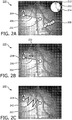
- an endoscope image including overlaid indicators 200 is illustratively depicted, in accordance with one embodiment.
- a directional indicator 206 is overlaid on an endoscope image to show the direction from the center of the endoscope image 202 to the selected areas of interest 204.
- Guidance module 122 of FIG. 1 includes path module 126 to further aid the user (e.g., a surgeon or an assistant) in navigating the endoscope.
- path module 126 to further aid the user (e.g., a surgeon or an assistant) in navigating the endoscope.
- an endoscope trace 208 is overlaid onto an endoscope image to show the motion of the endoscope.
- the trace 208 is generated by tracking the position of one or more anatomical features that are located at the center of the endoscope image and overlaying an arrow to mark that location on the endoscope image.
- the current feature in the center of the image is overlaid with an arrow on the endoscope image, while continuing to track the features previously at the center of the image.
- a visual trail may be created to help a user steering an endoscope to navigate to the selected areas of interest 204.
- the direction of trace 208 may be compared to the direction of the target area of interest 204 to display an angular error using visual cues.
- a dial 210 can be displayed using hands 212 and 214 to indicate the angular offset between the motion of the endoscope 208 and the direction of the selected areas of interest 206, respectively.
- Other visual cues indicating the angular error are also contemplated. For example, an angle (e.g., in degrees) between direction to selected areas of interest 206 and motion of the endoscope 208 can be displayed.
- Guidance module 122 may also include distance module 128, which is configured to indicate the distance from the center of the endoscope image to the target areas of interest.
- the endoscope image may include directional indicator 206 showing the direction from the center of the endoscope image 202 to target area of interest 204.
- a distance 222 e.g., in pixels
- a line between the center of the endoscope image 202 and the selected areas of interest 204 can be represented as a function of distance. For example, referring for a moment to FIG.
- an endoscope image with an overlaid distance indicator using a virtual spring 240 is illustratively depicted in accordance with one embodiment.
- a virtual spring 242 joins the center of the endoscope image 202 with the selected areas of interest 204.
- the virtual spring may appear stretched as the distance between the two points grows further apart and compressed as the distance becomes closer.
- Other distance error indicators have also been contemplated.
- the color of the line between the center of the endoscope image 202 and the selected areas of interest 204 can change with distance, with a legend displayed on the screen to define the colors.
- the thickness of the line can be modified as distance changes.
- direction module 124 of FIG. 1 may overlay anatomical reference directions onto the endoscope image.
- preoperative and intraoperative images 112 are registered with endoscope images 114 by registration module 118, the anatomical reference directions of the preoperative and intraoperative images are determined.
- the anatomical reference directions are transformed into the endoscope coordinate system and overlaid onto the endoscope image.
- Anatomical reference directions may include, but are not limited to, anterior/posterior, left/right and head/foot directions. Other anatomical directions are also contemplated.
- a user navigates the endoscope 102.
- the endoscope motion is traced, as discussed above, to determine if endoscope 102 has reached the selected areas of interest.
- the operations of the guidance module 122 are repeated until the selected areas of interest are reached. Once the selected area of interest is reached, the process ends.
- program 116 of FIG. 1 may also include actuation module 130 to further aid the user in navigating the endoscope 102.
- Actuation module 130 is configured to pre-orient camera 106 using actuated platform 104 such that a coordinate system of the camera corresponds with a preferred coordinate system of the user.
- Actuation module 130 receives the direction a user prefers to correspond to the, e.g., upwards direction. For example, a user may physically move the endoscope in the preferred upwards direction.
- the angle between the physical motion of the endoscope and the true upwards direction of the endoscope image is computed and passed as an input to the actuated platform, which pre-orients the camera accordingly. It is noted that the corresponding direction is not limited to the upwards direction, but rather may include any direction.
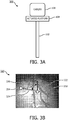
- FIG. 3A a system for orienting an endoscope camera's coordinate system with an endoscope user's coordinate system 300 is illustratively depicted in accordance with one embodiment.
- Camera 106 is mounted on actuated platform 104 on scope 102.
- Actuated platform 104 rotates according to the received angle to orient the camera accordingly.
- FIG. 3B an illustrative example of an endoscope image with overlaid orienting indicators 320 is shown in accordance with one embodiment.
- a user moves the endoscope in a preferred upwards direction, resulting in motion of endoscope 324 from center of image indicator 202.
- the angle between motion of the endoscope 324 and the true upwards direction of the image 322 is computed to determine angle 326, which is passed to actuated platform 104 to orient the camera accordingly.
- scope images are registered with preoperative and/or intraoperative images.
- Scope images are preferably images of an endoscope including a camera to capture intraoperative images of the operation site. Endoscope images may preferably include video.
- Preoperative and/or intraoperative images are received from systems including, but not limited to, an MRI system, a CT system, an x-ray system, a 3D ultrasound system, etc. Registration is performed as is known in the art.
- areas of interest may be selected on the preoperative and intraoperative images.
- the selected areas of interest may be transformed from the preoperative and intraoperative images coordinate frame to the endoscope image coordinate frame. This may include use of the registration transformation determined in block 402.
- the direction from the current center of the endoscope image to the selected areas of interest is determined in the endoscope image.
- guidance indicators are overlaid onto the endoscope image.
- Guidance indicators may include, for example, but are not limited to, a directional indicator, an endoscope tracer, a directional error indicator, a distance error indicator, and anatomical reference direction indicator. Other guidance indicators are also contemplated.
- guidance indicators may include a directional indicator overlaid onto the endoscope image to show the direction from the current center of the endoscope image to the selected areas of interest.
- an endoscope trace may be overlaid onto the endoscope image showing the endoscope motion. The trace may be generated by tracking the position of each anatomical feature that is located at the center of the endoscope image and overlaying an arrow to mark that location on the endoscope image. At each frame or period of frames, the current feature in the center of the image is overlaid with an arrow on the endoscope image, while continuing to track the features previously at the center of the image. Continuing this process, the positions of each of the features are displayed in the endoscope image to provide a visual trail that can help a user navigate the endoscope.
- the endoscope trace may be compared to the direction of the selected areas of interest to determine an angular error, representing the angular offset between the motion of the endoscope and the direction to the selected areas of interest.
- the angular error may be overlaid onto the endoscope image using visual cues.
- a dial including two hands is overlaid onto the endoscope image, where each hand indicates the trace of the endoscope and direction to the selected areas of interest, respectively.
- angular error may be indicated by displaying the angle (e.g., in degrees) on the endoscope image.
- guidance indicators may include a distance error indictor overlaid onto the endoscope image.
- a distance error can be overlaid onto the endoscope images to help the user navigate the endoscope.
- the distance e.g., in pixels
- the line that joins the center of the endoscope image and the selected areas of interest can be represented as a function of distance. This may include representing the line as a virtual spring, which may appear stretched as the distance gets larger and compressed as the distance gets smaller. Alternatively, the color or thickness of the line may change according to distance. Other representations of distance error are also contemplated.
- anatomical reference directions may be overlaid onto the endoscope images.
- the anatomical reference directions of the preoperative and intraoperative images are determined and transformed into the endoscope view.
- Anatomical reference directions may include, for example, anterior/posterior, left/right and head/foot directions. Other anatomical reference directions are also contemplated.
- a user can navigate the endoscope with increased efficiency.
- the endoscope motion is tracked to determine if the selection area of interest is reached.
- steps 408, 410, 414 and 416 are repeated until the selected area of interest is reached in block 418.
- the present principles aid a user to navigate an endoscope efficiently, resulting in reduced operating room time.
- a camera of the endoscope in block 412, can be pre-oriented such that a coordinate system of the camera corresponds with a preferred coordinate system of the user.
- a user can indicate a preferred, e.g., upwards direction. This may include a user physically moving the endoscope in the preferred upwards direction.
- the angle between the physical motion of the endoscope and the actual upwards direction of the endoscope image is computed and passed as an input to an actuated platform mounted between the camera and endoscope.
- the actuated platform rotates the camera according to the received angle to aid the user in navigating the endoscope.
- the corresponding direction is not limited to the upwards direction, but rather may include any direction.
Description
- This disclosure relates to medical instruments and more particularly to guidance tools for manually steering endoscopes.
- Coronary artery bypass grafting (CABG) is a surgical procedure for the revascularization of obstructed coronary arteries. Minimally invasive CABG is performed using an endoscope as the only feedback from the operating site. In a standard setup for a minimally invasive CABG procedure, a surgeon uses both hands to hold instruments while an assistant holds the endoscope. The endoscope is typically inserted into the chest cavity from the right side of the patient or from the posterior-anterior direction. This may result in three relevant coordinate systems: the coordinate system of the endoscope (e.g., camera), the coordinate system of the surgeon, and the coordinate system of the assistant. This can lead to a number of problems. For instance, while the surgeon is looking forward at the screen, the camera is representing the anatomy from a side view. In addition, if the camera located on the top of the endoscope were to be rotated 180°, the image would appear inverted on the screen. However, there is currently no way of knowing the camera's orientation. Moreover, the assistant has to respond to instructions from the surgeon as to how to move the endoscope. An order such as "right" may correspond to moving the endoscope left and down, which may be highly counter-intuitive for the assistant and may lead to a trial and error approach. These problems may lead to prolonged operating room time and inefficiencies in the workflow. International Patent Application
WO 2010/111090 A1 describes providing directional guidance to an operator of an endoscopic device by displaying graphical representations of vectors adjacent a current image captured by an image capturing device disposed at a tip of the endoscopic device and being displayed at the time on a display screen, wherein the graphical representations of the vectors point in directions that the endoscope tip is to be steered in order to move towards associated landmarks such as anatomic structures. -
US 2008/0287783 A1 discloses a system and method to track a delivery of a surgical instrument through an imaged subject. The system comprises an imaging system including an imaging probe, wherein the imaging probe includes a transducer array operable to acquire image data through a range of motion about a longitudinal axis and in a direction of image acquisition with the imaging probe stationary. The system also includes a tracking system to track a position of the imaging probe relative to a second object tracked by the tracking system, and a display illustrative of a direction of image acquisition of the imaging probe relative to an illustration of a position of the second object.US 2008/262297 A1 andUS 2006/004286 A1 disclose further systems and methods concerning endoscope navigation. - In accordance with the present principles, novel solutions for guidance tools for manually steering an endoscope are provided. In one embodiment, the present principles include registering preoperative and/or intraoperative images with images of an endoscope. Visual cues maybe overlaid onto the endoscope view as guidance tools to permit a user to navigate the endoscope towards selected areas of interest. The motion of the endoscope may be tracked in real-time using image features to update the visual cues. In another embodiment, the present principles may pre-orient a camera of an endoscope such that the coordinate system of the camera corresponds with a preferred coordinate system of the user. The camera of the endoscope may be mounted on an actuated platform, which pre-orients the endoscope by rotating the camera to correspond to a preferred direction of the user. Advantageously, the present principles provide for efficient steering to manually navigate an endoscope. This may lead to reduced operating room time and a more efficient workflow.
- A system for guided endoscope navigation includes a registration module configured to register a first set of images being preoperative and/or intraoperative images with a second set of images of an endoscope. A selection module is configured to receive selected areas of interest on the first set of images and transform the selected areas of interest to an endoscope coordinate frame. A guidance module is configured to overlay guidance tools onto the second set of images to permit a user of the endoscope to navigate the endoscope to the selected areas of interest. The guidance module includes a path module configured to overlay a path of a motion of the endoscope onto the second set of images. The path overlaid by the path module creates a visual trail of the motion of the endoscope, the path being generated by tracking positions of anatomical features including at least one of anatomical features located at a center of a frame of the second set of images and anatomical features previously located at the center of the frame.
- A system for guided endoscope navigation includes a registration module configured to, using a processor, register a first set of images with a second set of images of an endoscope. A selection module is configured to receive selected areas of interest on the first set of images and transform the selected areas of interest to an endoscope coordinate frame. A guidance module is configured to overlay guidance tools onto the second set of images. An actuation module is configured to orient a camera of the endoscope such that a coordinate system of the camera corresponds with a coordinate system of the user to permit a user of the endoscope to navigate to the selected areas of interest.
- A computer program product comprising instructions which when executed on a computer cause the computer to carry out a method for guided endoscope navigation includes registering a first set of images preoperative and/or intraoperative images with a second set of images of an endoscope. Areas of interest are selected on the first set of images and the selected areas of interest are transformed to an endoscope coordinate frame. Guidance tools are overlaid onto the second set of images to permit a user of the endoscope to navigate the endoscope to the selected areas of interest, wherein the overlaying includes overlaying a path of a motion of the endoscope onto the second set of images. The path overlaid by the path module creates a visual trail of the motion of the endoscope, the path being generated by tracking positions of anatomical features including at least one of anatomical features located at a center of a frame of the second set of images and anatomical features previously located at the center of the frame.
- These and other objects, features and advantages of the present disclosure will become apparent from the following detailed description of illustrative embodiments thereof, which is to be read in connection with the accompanying drawings.
- This disclosure will present in detail the following description of preferred embodiments with reference to the following figures wherein:
-
FIG. 1 is a block/flow diagram showing a system for manually steering an endoscope using guidance tools, in accordance with one embodiment; -
FIG. 2A is an illustrative example of an endoscope image with overlaid direction, path and directional error indicator, in accordance with one embodiment; -
FIG. 2B is an illustrative example of an endoscope image with an overlaid distance error indicator displaying distance, in accordance with one embodiment; -
FIG. 2C is an illustrative example of an endoscope image with an overlaid distance error indicator using a virtual spring, in accordance with one embodiment; -
FIG. 3A is a block/flow diagram showing a system for orienting an endoscope camera's coordinate system with an endoscope user's coordinate system, in accordance with one embodiment; -
FIG. 3B is an illustrative example of an endoscope image to orient an endoscope camera's coordinate system with an endoscope user's coordinate system, in accordance with one embodiment; and -
FIG. 4 is a block/flow diagram showing a method for manually steering an endoscope using guidance tools, in accordance with one embodiment. - In accordance with the present principles, embodiments for a system, apparatus and method provide guidance tools for manually steering an endoscope. In an embodiment according to the invention preoperative and/or intraoperative images are registered with images of an endoscope. Visual cues are overlaid onto the endoscope view as guidance tools to permit a user (e.g., surgeon assistant) to steer the endoscope towards selected areas of interest. The motion of the endoscope is tracked in real-time using image features to update the visual cues. Visual cues according to the invention are anatomical features, additional features include, but are not limited to: a direction indicator showing the direction to the selected areas of interest, an endoscope tracer showing the motion of the endoscope, a directional error indictor showing the angular error of the motion of the endoscope compared to the direction to the selected areas of interest, a distance error indicator showing distance to the selected areas of interest, and anatomical reference directions showing anatomical directions. Other visual cues are possible and have been contemplated within the scope of the present principles.
- In another embodiment, the present principles may pre-orient an endoscope camera's coordinate system with a user's preferred coordinate system. In order to pre-orient the camera in a preferred direction, the camera of the endoscope may be mounted on an actuated platform. The endoscope user moves the endoscope in the physical direction in which he or she would prefer to correspond to the, e.g., "upwards" direction in the image. The angle between the physical movement of the endoscope and the actual upwards direction in the image is determined and the actuated platform rotates the camera accordingly to pre-orient the coordinate frames. It is noted that the present principles are not limited to the upwards direction, but may include any direction.
- It should be understood that the present invention will be described in terms of an endoscope; however, the teachings of the present invention are much broader and are applicable to any optical scope that can be employed in internal viewing of branching, curved, coiled or other shaped systems. In some embodiments, the present principles are employed in tracking or analyzing complex biological or mechanical systems (e.g., digestive systems, circulatory systems, piping systems, passages, mines, caverns, etc.). In particular, the present principles are applicable to internal tracking procedures of biological systems, procedures in all areas of the body such as the lungs, gastro-intestinal tract, excretory organs, blood vessels, etc. The elements depicted in the FIGS. may be implemented in various combinations of hardware and software and provide functions which may be combined in a single element or multiple elements. Embodiments described herein are preferably displayed for viewing on a display monitor. Such monitors may include any suitable display device including but not limited to handheld displays (e.g., on personal digital assistants, telephone devices, etc.), computer displays, televisions, designated monitors, etc. Depending of the scope, the display may be provided as part of the system or may be a separate unit or device.
- It should also be understood that the optical scopes may include a plurality of different devices connected to or associated with the scope. Such devices may include a light, a cutting device, a brush, a vacuum, a camera, etc. These components may be formed integrally with a head on a distal end portion of the scope. The optical scopes may include a camera disposed at a tip of the scope or a camera may be disposed at the end of an optical cable opposite the tip.
- The functions of the various elements shown in the FIGS. can be provided through the use of dedicated hardware as well as hardware capable of executing software in association with appropriate software. When provided by a processor, the functions can be provided by a single dedicated processor, by a single shared processor, or by a plurality of individual processors, some of which can be shared. Moreover, explicit use of the term "processor" or "controller" should not be construed to refer exclusively to hardware capable of executing software, and can implicitly include, without limitation, digital signal processor ("DSP") hardware, read-only memory ("ROM") for storing software, random access memory ("RAM"), non-volatile storage, etc.
- Moreover, all statements herein reciting principles, aspects, and embodiments of the invention, as well as specific examples thereof, are intended to encompass both structural and functional equivalents thereof. Additionally, it is intended that such equivalents include both currently known equivalents as well as equivalents developed in the future (i.e., any elements developed that perform the same function, regardless of structure). Thus, for example, it will be appreciated by those skilled in the art that the block diagrams presented herein represent conceptual views of illustrative system components and/or circuitry embodying the principles of the invention. Similarly, it will be appreciated that any flow charts, flow diagrams and the like represent various processes which may be substantially represented in computer readable storage media and so executed by a computer or processor, whether or not such computer or processor is explicitly shown.
- Furthermore, embodiments of the present invention can take the form of a computer program product accessible from a computer-usable or computer-readable storage medium providing program code for use by or in connection with a computer or any instruction execution system. For the purposes of this description, a computer-usable or computer readable storage medium can be any apparatus that may include, store, communicate, propagate, or transport the program for use by or in connection with the instruction execution system, apparatus, or device. The medium can be an electronic, magnetic, optical, electromagnetic, infrared, or semiconductor system (or apparatus or device) or a propagation medium. Examples of a computer-readable medium include a semiconductor or solid state memory, magnetic tape, a removable computer diskette, a random access memory (RAM), a read-only memory (ROM), a rigid magnetic disk and an optical disk. Current examples of optical disks include compact disk - read only memory (CD-ROM), compact disk - read/write (CD-R/W), Blu-Ray™ and DVD.
- Referring now to the drawings in which like numerals represent the same or similar elements and initially to
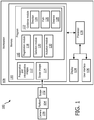
FIG. 1 , asystem 100 for manually steering an endoscope using guidance tools is illustratively depicted in accordance with one embodiment.System 100 may include a workstation or console 108 from which procedures (e.g., endoscopy) are supervised and managed.Workstation 108 preferably includes one ormore processors 138 andmemory 110 for storing programs and applications. It should be understood that the functions and components ofsystem 100 may be integrated into one or more workstations or systems. -
Memory 110 may storeimages 112.Images 112 may include preoperative images and intraoperative images, which may be received from systems including, but not limited to, a magnetic resonance imaging (MRI) system, a computed tomography (CT) system, an x-ray system, a 3-D ultrasound system, etc.Memory 110 may also storescope images 114 received fromscope 102. In a preferred embodiment,scope 102 is an endoscope to capture intraoperative images of the operation site fromcamera 106.Scope images 114 may preferably include video fromcamera 106 ofendoscope 102. - The present principles may be applied for different applications of endoscopically-guided minimally invasive surgery. For example, the present principles may be used for cardiac surgery (e.g., minimally invasive coronary artery bypass grafting, atrial septal defect closure, valve repair/replacement, etc.), laparoscopic surgery (e.g., hysterectomy, prostatectomy, gall bladder surgery, etc.), natural orifice transluminal surgery, pulmonary/bronchoscopy surgery, neurosurgical interventions, and videos assisted thoracic surgery. However, it is noted that the teachings of the present principles are much broader than this, as
scope 102 may include any type of scope for various types of applications. In one exemplary embodiment, the present principles may be applied to manually navigate a plumber's snake through piping. Other applications are also contemplated. -
Workstation 108 may include one ormore displays 134 for viewing preoperative andintraoperative images 112 andscope images 114 including guidance features of the present principles. Thedisplay 134 may also permit a user to interact withworkstation 108 and its components and functions. This is further facilitated by a user interface 136, which may include a keyboard, mouse, joystick, or any other peripheral or control to permit user interaction withworkstation 108. - A computer implemented
program 116 is stored inmemory 110 ofworkstation 108. Theprogram 116 may include a number of modules, each configured to perform various functions. It should be understood that the modules may be implemented in various combinations of hardware and software. -
Program 116 may includeregistration module 118, which is configured to perform registration between images 112 (e.g., preoperative images and/or intraoperative images) and scope (e.g., endoscope)images 114. Registration is performed as is known in the art. -
Program 116 may also includeselection module 120, which is configured to allow a user (e.g., a surgeon) to select areas of interest on the preoperative and intraoperative images 112 (e.g., CT or x-ray). For example, a selected area of interest may be a target bypass artery in a coronary artery bypass grafting procedure.Selection module 120 may include the use ofdisplay 134 and user interface 136 to facilitate this selection.Selection module 120 then transforms the selected areas of interest from the preoperative and/or intraoperative image coordinate frame to the endoscope coordinate frame using the registration transformation determined inregistration module 118. -
Program 116 may includeguidance module 122, which is configured to use the selected areas of interest in the endoscope view to determine a number of guidance indicators.Guidance module 122 may include, but is not limited to, any or all ofdirection module 124,path module 126 anddistance module 128. Other indicators have also been contemplated. -
Direction module 124 determines a direction from the current center of the endoscope image to the selected areas of interest to overlay a directional indicator onto the endoscope image. Referring for a moment toFIG. 2A , an endoscope image including overlaidindicators 200 is illustratively depicted, in accordance with one embodiment. Adirectional indicator 206 is overlaid on an endoscope image to show the direction from the center of theendoscope image 202 to the selected areas ofinterest 204. -
Guidance module 122 ofFIG. 1 includespath module 126 to further aid the user (e.g., a surgeon or an assistant) in navigating the endoscope. Referring back for a moment toFIG. 2 A , anendoscope trace 208 is overlaid onto an endoscope image to show the motion of the endoscope. Thetrace 208 is generated by tracking the position of one or more anatomical features that are located at the center of the endoscope image and overlaying an arrow to mark that location on the endoscope image. At each frame or period of frames, the current feature in the center of the image is overlaid with an arrow on the endoscope image, while continuing to track the features previously at the center of the image. Continuing this process, a visual trail may be created to help a user steering an endoscope to navigate to the selected areas ofinterest 204. - The direction of
trace 208 may be compared to the direction of the target area ofinterest 204 to display an angular error using visual cues. In one embodiment, adial 210 can be displayed usinghands endoscope 208 and the direction of the selected areas ofinterest 206, respectively. Other visual cues indicating the angular error are also contemplated. For example, an angle (e.g., in degrees) between direction to selected areas ofinterest 206 and motion of theendoscope 208 can be displayed. -
Guidance module 122 may also includedistance module 128, which is configured to indicate the distance from the center of the endoscope image to the target areas of interest. Referring for a moment toFIG. 2B , an endoscope image with an overlaiddistance error indicator 220 is illustratively depicted in accordance with one embodiment. The endoscope image may includedirectional indicator 206 showing the direction from the center of theendoscope image 202 to target area ofinterest 204. In one embodiment, a distance 222 (e.g., in pixels) can be indicated as a number on the screen. In another embodiment, a line between the center of theendoscope image 202 and the selected areas ofinterest 204 can be represented as a function of distance. For example, referring for a moment toFIG. 2C , an endoscope image with an overlaid distance indicator using avirtual spring 240 is illustratively depicted in accordance with one embodiment. Avirtual spring 242 joins the center of theendoscope image 202 with the selected areas ofinterest 204. The virtual spring may appear stretched as the distance between the two points grows further apart and compressed as the distance becomes closer. Other distance error indicators have also been contemplated. For example, the color of the line between the center of theendoscope image 202 and the selected areas ofinterest 204 can change with distance, with a legend displayed on the screen to define the colors. In another embodiment, the thickness of the line can be modified as distance changes. - In yet another embodiment of the present principles,
direction module 124 ofFIG. 1 may overlay anatomical reference directions onto the endoscope image. As preoperative andintraoperative images 112 are registered withendoscope images 114 byregistration module 118, the anatomical reference directions of the preoperative and intraoperative images are determined. The anatomical reference directions are transformed into the endoscope coordinate system and overlaid onto the endoscope image. Anatomical reference directions may include, but are not limited to, anterior/posterior, left/right and head/foot directions. Other anatomical directions are also contemplated. - Using the overlaid guidance indicators of
guidance module 122, a user navigates theendoscope 102. The endoscope motion is traced, as discussed above, to determine ifendoscope 102 has reached the selected areas of interest. The operations of theguidance module 122 are repeated until the selected areas of interest are reached. Once the selected area of interest is reached, the process ends. - In one embodiment of the present principles,
program 116 ofFIG. 1 may also includeactuation module 130 to further aid the user in navigating theendoscope 102.Actuation module 130 is configured topre-orient camera 106 using actuatedplatform 104 such that a coordinate system of the camera corresponds with a preferred coordinate system of the user.Actuation module 130 receives the direction a user prefers to correspond to the, e.g., upwards direction. For example, a user may physically move the endoscope in the preferred upwards direction. The angle between the physical motion of the endoscope and the true upwards direction of the endoscope image is computed and passed as an input to the actuated platform, which pre-orients the camera accordingly. It is noted that the corresponding direction is not limited to the upwards direction, but rather may include any direction. - Referring now to
FIG. 3A , a system for orienting an endoscope camera's coordinate system with an endoscope user's coordinatesystem 300 is illustratively depicted in accordance with one embodiment.Camera 106 is mounted on actuatedplatform 104 onscope 102. Actuatedplatform 104 rotates according to the received angle to orient the camera accordingly. Referring for a moment forFIG. 3B , an illustrative example of an endoscope image with overlaid orientingindicators 320 is shown in accordance with one embodiment. A user moves the endoscope in a preferred upwards direction, resulting in motion ofendoscope 324 from center ofimage indicator 202. The angle between motion of theendoscope 324 and the true upwards direction of theimage 322 is computed to determineangle 326, which is passed to actuatedplatform 104 to orient the camera accordingly. - Referring now to
FIG. 4 , a method for manually steering an endoscope usingguidance tools 400 is illustratively depicted in accordance with one embodiment. Inblock 402, scope images are registered with preoperative and/or intraoperative images. Scope images are preferably images of an endoscope including a camera to capture intraoperative images of the operation site. Endoscope images may preferably include video. Preoperative and/or intraoperative images are received from systems including, but not limited to, an MRI system, a CT system, an x-ray system, a 3D ultrasound system, etc. Registration is performed as is known in the art. - In
block 404, areas of interest may be selected on the preoperative and intraoperative images. Inblock 406, the selected areas of interest may be transformed from the preoperative and intraoperative images coordinate frame to the endoscope image coordinate frame. This may include use of the registration transformation determined inblock 402. - In
block 408, the direction from the current center of the endoscope image to the selected areas of interest is determined in the endoscope image. Using this direction, inblock 410, guidance indicators are overlaid onto the endoscope image. Guidance indicators may include, for example, but are not limited to, a directional indicator, an endoscope tracer, a directional error indicator, a distance error indicator, and anatomical reference direction indicator. Other guidance indicators are also contemplated. - In one embodiment, guidance indicators may include a directional indicator overlaid onto the endoscope image to show the direction from the current center of the endoscope image to the selected areas of interest. In another embodiment, an endoscope trace may be overlaid onto the endoscope image showing the endoscope motion. The trace may be generated by tracking the position of each anatomical feature that is located at the center of the endoscope image and overlaying an arrow to mark that location on the endoscope image. At each frame or period of frames, the current feature in the center of the image is overlaid with an arrow on the endoscope image, while continuing to track the features previously at the center of the image. Continuing this process, the positions of each of the features are displayed in the endoscope image to provide a visual trail that can help a user navigate the endoscope.
- In yet another embodiment, the endoscope trace may be compared to the direction of the selected areas of interest to determine an angular error, representing the angular offset between the motion of the endoscope and the direction to the selected areas of interest. The angular error may be overlaid onto the endoscope image using visual cues. In an embodiment, a dial including two hands is overlaid onto the endoscope image, where each hand indicates the trace of the endoscope and direction to the selected areas of interest, respectively. In another example, angular error may be indicated by displaying the angle (e.g., in degrees) on the endoscope image.
- In one embodiment, guidance indicators may include a distance error indictor overlaid onto the endoscope image. As the endoscope is moved, the distance from the center of the endoscope image to the selected areas of interest will vary. A distance error can be overlaid onto the endoscope images to help the user navigate the endoscope. For example, the distance (e.g., in pixels) can be indicated as a number of the screen. In another example, the line that joins the center of the endoscope image and the selected areas of interest can be represented as a function of distance. This may include representing the line as a virtual spring, which may appear stretched as the distance gets larger and compressed as the distance gets smaller. Alternatively, the color or thickness of the line may change according to distance. Other representations of distance error are also contemplated.
- In another embodiment, anatomical reference directions may be overlaid onto the endoscope images. As preoperative and intraoperative images are registered (block 402), the anatomical reference directions of the preoperative and intraoperative images are determined and transformed into the endoscope view. Anatomical reference directions may include, for example, anterior/posterior, left/right and head/foot directions. Other anatomical reference directions are also contemplated.
- In
block 414, using the guidance indicators overlaid onto the endoscope image, a user can navigate the endoscope with increased efficiency. The endoscope motion is tracked to determine if the selection area of interest is reached. Inblock 416, if the selected area of interest is not reached,steps block 418. Advantageously, the present principles aid a user to navigate an endoscope efficiently, resulting in reduced operating room time. - In one embodiment of the present invention, in
block 412, a camera of the endoscope can be pre-oriented such that a coordinate system of the camera corresponds with a preferred coordinate system of the user. A user can indicate a preferred, e.g., upwards direction. This may include a user physically moving the endoscope in the preferred upwards direction. The angle between the physical motion of the endoscope and the actual upwards direction of the endoscope image is computed and passed as an input to an actuated platform mounted between the camera and endoscope. The actuated platform rotates the camera according to the received angle to aid the user in navigating the endoscope. It is noted that the corresponding direction is not limited to the upwards direction, but rather may include any direction. - In interpreting the appended claims, it should be understood that:
- a) the word "comprising" does not exclude the presence of other elements or acts than those listed in a given claim;
- b) the word "a" or "an" preceding an element does not exclude the presence of a plurality of such elements;
- c) any reference signs in the claims do not limit their scope;
- d) several "means" may be represented by the same item or hardware or software implemented structure or function; and
- e) no specific sequence of acts is intended to be required unless specifically indicated.
- Having described preferred embodiments for guidance tools to manually steer endoscope using pre-operative and intra-operative 3D images (which are intended to be illustrative and not limiting), it is noted that modifications and variations can be made by persons skilled in the art in light of the above teachings. It is therefore to be understood that changes may be made in the particular embodiments of the disclosure disclosed which are within the scope of the embodiments disclosed herein as outlined by the appended claims.
Claims (13)
- A guidance system for endoscope navigation, comprising:a registration module (118) configured to register a first set of images (112) being preoperative and/or intraoperative images with a second set of images (114) of an endoscope (102);a selection module (120) configured to receive selected areas of interest on the first set of images and transform the selected areas of interest to an endoscope coordinate frame; anda guidance module (122) configured to overlay guidance tools onto the second set of images to permit a user of the endoscope to navigate the endoscope to the selected areas of interest,
wherein the guidance module includes a path module (126) configured to overlay a path (208) of a motion of the endoscope onto the second set of images; andcharacterised in that the path (208) overlaid by the path module (126) creates a visual trail of the motion of the endoscope, the path (208) being generated by tracking positions of anatomical features including at least one of anatomical features located at a center of a frame of the second set of images and anatomical features previously located at the center of the frame. - The system as recited in claim 1, further comprising:
an actuation module (130) configured to orient a camera (106) of the endoscope such that a coordinate system of the camera corresponds with a coordinate system of the user. - The system as recited in claim 2, wherein the actuation module (130) is further configured to rotate an actuation platform including the camera in accordance with an angle between a first direction and an actual direction.
- The system as recited in claim 1, wherein the guidance module (122) includes a direction module (124) configured to overlay a direction indicator (206) onto the second set of images, the direction indicator being from a center of a frame of the second set of images (202) to the selected areas of interest (204).
- The system as recited in claim 4, wherein the direction module (124) is further configured to overlay an angular error indicator (210) onto the second set of images to show an angular error between the direction indicator (206) and a path (208) of a motion of the endoscope.
- The system as recited in claim 1, wherein the guidance module (122) includes a distance module (128) configured to overlay a distance indicator (222) onto the second set of images indicating a distance from a center of a frame of the second set of images (202) to the selected areas of interest (204).
- The system as recited in claim 6, wherein the distance indicator (222) is a line (242) from the center of the frame to the selected areas of interest that varies as a function of distance.
- The system as recited in claim 7, wherein the line is a virtual spring (242) that appears compressed as the distance decreases and stretched as the distance increases.
- The system as recited in claim 7, wherein a color of the line varies as a function of distance.
- The system as recited in claim 1, wherein the guidance module (122) includes a direction module (124) configured to overlay anatomical directions of the first set of images onto the second set of images.
- A computer program product comprising instructions which when executed on a computer cause the computer to carry out a method for guided endoscope navigation, the method comprising:registering (402) a first set of images being preoperative and/or intraoperative images with a second set of images of an endoscope andoverlaying (410) guidance tools onto the second set of images to enable a user of the endoscope to navigate the endoscope to areas of interest being selectable on the first set of images and transformable to an endoscope coordinate frame,
wherein overlaying (410) includes overlaying a path (208) of a motion of the endoscope onto the second set of images; andcharacterised in that the path (208) overlaid by a path module (126) creates a visual trail of the motion of the endoscope, the path (208) being generated by tracking positions of anatomical features including at least one of anatomical features located at a center of a frame of the second set of images and anatomical features previously located at the center of the frame. - The computer program product as recited in claim 11, wherein the method further comprises:
orienting (412) a camera of the endoscope such that a coordinate system of the camera corresponds with a coordinate system of the user. - The computer program product as recited in claim 12, wherein orienting (412) includes rotating an actuation platform including the camera in accordance with an angle between a first direction and an actual direction of the first direction.
Applications Claiming Priority (2)
| Application Number | Priority Date | Filing Date | Title |
|---|---|---|---|
| US201261635327P | 2012-04-19 | 2012-04-19 | |
| PCT/IB2013/052797 WO2013156893A1 (en) | 2012-04-19 | 2013-04-08 | Guidance tools to manually steer endoscope using pre-operative and intra-operative 3d images |
Publications (2)
| Publication Number | Publication Date |
|---|---|
| EP2838412A1 EP2838412A1 (en) | 2015-02-25 |
| EP2838412B1 true EP2838412B1 (en) | 2020-09-09 |
Family
ID=48539312
Family Applications (1)
| Application Number | Title | Priority Date | Filing Date |
|---|---|---|---|
| EP13726277.0A Active EP2838412B1 (en) | 2012-04-19 | 2013-04-08 | Guidance tools to manually steer endoscope using pre-operative and intra-operative 3d images |
Country Status (6)
| Country | Link |
|---|---|
| US (1) | US11452464B2 (en) |
| EP (1) | EP2838412B1 (en) |
| JP (1) | JP6174676B2 (en) |
| CN (1) | CN104244800B (en) |
| RU (1) | RU2668490C2 (en) |
| WO (1) | WO2013156893A1 (en) |
Families Citing this family (39)
| Publication number | Priority date | Publication date | Assignee | Title |
|---|---|---|---|---|
| US9510771B1 (en) | 2011-10-28 | 2016-12-06 | Nuvasive, Inc. | Systems and methods for performing spine surgery |
| US9295372B2 (en) * | 2013-09-18 | 2016-03-29 | Cerner Innovation, Inc. | Marking and tracking an area of interest during endoscopy |
| US9848922B2 (en) | 2013-10-09 | 2017-12-26 | Nuvasive, Inc. | Systems and methods for performing spine surgery |
| CN105611884B (en) | 2013-10-09 | 2019-06-28 | 纽文思公司 | The system for being designed in art during vertebra program of performing the operation and evaluating spine malformation correction |
| US20150157197A1 (en) * | 2013-12-09 | 2015-06-11 | Omer Aslam Ilahi | Endoscopic image overlay |
| WO2015121764A1 (en) | 2014-02-11 | 2015-08-20 | Koninklijke Philips N.V. | Spatial visualization of internal mammary artery during minimally invasive bypass surgery |
| DE102014203097A1 (en) * | 2014-02-20 | 2015-08-20 | Siemens Aktiengesellschaft | A method of assisting navigation of an endoscopic device |
| KR102397254B1 (en) * | 2014-03-28 | 2022-05-12 | 인튜어티브 서지컬 오퍼레이션즈 인코포레이티드 | Quantitative three-dimensional imaging of surgical scenes |
| WO2015149041A1 (en) * | 2014-03-28 | 2015-10-01 | Dorin Panescu | Quantitative three-dimensional visualization of instruments in a field of view |
| JP2017519562A (en) | 2014-06-17 | 2017-07-20 | ニューヴェイジヴ,インコーポレイテッド | System and method for planning, performing, and evaluating spinal correction during surgery |
| WO2016072288A1 (en) * | 2014-11-06 | 2016-05-12 | ソニー株式会社 | Endoscopic device, method for operating endoscopic device, and program |
| US10013808B2 (en) | 2015-02-03 | 2018-07-03 | Globus Medical, Inc. | Surgeon head-mounted display apparatuses |
| US10695099B2 (en) | 2015-02-13 | 2020-06-30 | Nuvasive, Inc. | Systems and methods for planning, performing, and assessing spinal correction during surgery |
| US10406054B1 (en) | 2015-02-18 | 2019-09-10 | Nuvasive, Inc. | Systems and methods for facilitating surgical procedures |
| WO2017006449A1 (en) * | 2015-07-08 | 2017-01-12 | オリンパス株式会社 | Endoscope apparatus |
| JP6835850B2 (en) * | 2015-12-29 | 2021-02-24 | コーニンクレッカ フィリップス エヌ ヴェKoninklijke Philips N.V. | Systems, control units, and methods for controlling surgical robots |
| WO2017122322A1 (en) * | 2016-01-14 | 2017-07-20 | オリンパス株式会社 | Medical manipulator system |
| WO2017127838A1 (en) | 2016-01-22 | 2017-07-27 | Nuvasive, Inc. | Systems and methods for facilitating spine surgery |
| EP3422940B1 (en) | 2016-03-02 | 2021-06-16 | Nuvasive, Inc. | Systems and methods for spinal correction surgical planning |
| CN109069207B (en) * | 2016-03-17 | 2021-09-10 | 皇家飞利浦有限公司 | Robot system, control unit thereof, and computer-readable storage medium |
| WO2018005842A1 (en) | 2016-06-30 | 2018-01-04 | Intuitive Surgical Operations, Inc. | Graphical user interface for displaying guidance information in a plurality of modes during an image-guided procedure |
| US11819284B2 (en) | 2016-06-30 | 2023-11-21 | Intuitive Surgical Operations, Inc. | Graphical user interface for displaying guidance information during an image-guided procedure |
| CN110621252B (en) | 2017-04-18 | 2024-03-15 | 直观外科手术操作公司 | Graphical user interface for monitoring image-guided procedures |
| US20190254753A1 (en) | 2018-02-19 | 2019-08-22 | Globus Medical, Inc. | Augmented reality navigation systems for use with robotic surgical systems and methods of their use |
| JP6990292B2 (en) | 2018-02-21 | 2022-01-12 | オリンパス株式会社 | Medical system and how to operate the medical system |
| CN112672709A (en) * | 2018-07-31 | 2021-04-16 | 直观外科手术操作公司 | System and method for tracking the position of a robotically-manipulated surgical instrument |
| US11229492B2 (en) | 2018-10-04 | 2022-01-25 | Biosense Webster (Israel) Ltd. | Automatic probe reinsertion |
| CN110742690A (en) * | 2019-09-12 | 2020-02-04 | 东南大学苏州医疗器械研究院 | Method for configuring endoscope and terminal equipment |
| US11464581B2 (en) | 2020-01-28 | 2022-10-11 | Globus Medical, Inc. | Pose measurement chaining for extended reality surgical navigation in visible and near infrared spectrums |
| US11382699B2 (en) | 2020-02-10 | 2022-07-12 | Globus Medical Inc. | Extended reality visualization of optical tool tracking volume for computer assisted navigation in surgery |
| US11207150B2 (en) | 2020-02-19 | 2021-12-28 | Globus Medical, Inc. | Displaying a virtual model of a planned instrument attachment to ensure correct selection of physical instrument attachment |
| US11607277B2 (en) | 2020-04-29 | 2023-03-21 | Globus Medical, Inc. | Registration of surgical tool with reference array tracked by cameras of an extended reality headset for assisted navigation during surgery |
| US11382700B2 (en) | 2020-05-08 | 2022-07-12 | Globus Medical Inc. | Extended reality headset tool tracking and control |
| US11510750B2 (en) | 2020-05-08 | 2022-11-29 | Globus Medical, Inc. | Leveraging two-dimensional digital imaging and communication in medicine imagery in three-dimensional extended reality applications |
| US11153555B1 (en) | 2020-05-08 | 2021-10-19 | Globus Medical Inc. | Extended reality headset camera system for computer assisted navigation in surgery |
| JPWO2022044606A1 (en) * | 2020-08-24 | 2022-03-03 | ||
| US11737831B2 (en) | 2020-09-02 | 2023-08-29 | Globus Medical Inc. | Surgical object tracking template generation for computer assisted navigation during surgical procedure |
| US20220202500A1 (en) * | 2020-12-30 | 2022-06-30 | Canon U.S.A., Inc. | Intraluminal navigation using ghost instrument information |
| WO2022146996A1 (en) * | 2020-12-30 | 2022-07-07 | Intuitive Surgical Operations, Inc. | Systems for updating a graphical user interface based upon intraoperative imaging |
Family Cites Families (12)
| Publication number | Priority date | Publication date | Assignee | Title |
|---|---|---|---|---|
| US6332089B1 (en) * | 1996-02-15 | 2001-12-18 | Biosense, Inc. | Medical procedures and apparatus using intrabody probes |
| US7343195B2 (en) * | 1999-05-18 | 2008-03-11 | Mediguide Ltd. | Method and apparatus for real time quantitative three-dimensional image reconstruction of a moving organ and intra-body navigation |
| GR1004180B (en) * | 2000-03-28 | 2003-03-11 | ����������� ����� ��������� (����) | Method and system for characterization and mapping of tissue lesions |
| AU2001292836A1 (en) * | 2000-09-23 | 2002-04-02 | The Board Of Trustees Of The Leland Stanford Junior University | Endoscopic targeting method and system |
| EP2316328B1 (en) * | 2003-09-15 | 2012-05-09 | Super Dimension Ltd. | Wrap-around holding device for use with bronchoscopes |
| US20060036162A1 (en) * | 2004-02-02 | 2006-02-16 | Ramin Shahidi | Method and apparatus for guiding a medical instrument to a subsurface target site in a patient |
| US7720521B2 (en) * | 2004-04-21 | 2010-05-18 | Acclarent, Inc. | Methods and devices for performing procedures within the ear, nose, throat and paranasal sinuses |
| US8199984B2 (en) * | 2006-05-02 | 2012-06-12 | National University Corporation Nagoya University | System that assists in observing a luminal organ using the structure of the luminal organ |
| US20080287783A1 (en) * | 2007-05-16 | 2008-11-20 | General Electric Company | System and method of tracking delivery of an imaging probe |
| CN101826780B (en) * | 2009-03-07 | 2013-08-21 | 深圳先进技术研究院 | System for driving capsule endoscope |
| EP3023941B1 (en) | 2009-03-26 | 2019-05-08 | Intuitive Surgical Operations, Inc. | System for providing visual guidance for steering a tip of an endoscopic device towards one or more landmarks and assisting an operator in endoscopic navigation |
| WO2010122823A1 (en) * | 2009-04-20 | 2010-10-28 | オリンパスメディカルシステムズ株式会社 | Subject internal examination system |
-
2013
- 2013-04-08 RU RU2014146310A patent/RU2668490C2/en active
- 2013-04-08 JP JP2015506331A patent/JP6174676B2/en active Active
- 2013-04-08 WO PCT/IB2013/052797 patent/WO2013156893A1/en active Application Filing
- 2013-04-08 US US14/394,611 patent/US11452464B2/en active Active
- 2013-04-08 CN CN201380020657.8A patent/CN104244800B/en active Active
- 2013-04-08 EP EP13726277.0A patent/EP2838412B1/en active Active
Non-Patent Citations (1)
| Title |
|---|
| None * |
Also Published As
| Publication number | Publication date |
|---|---|
| WO2013156893A1 (en) | 2013-10-24 |
| EP2838412A1 (en) | 2015-02-25 |
| US20150073265A1 (en) | 2015-03-12 |
| JP2015514492A (en) | 2015-05-21 |
| JP6174676B2 (en) | 2017-08-02 |
| CN104244800B (en) | 2017-05-17 |
| RU2668490C2 (en) | 2018-10-01 |
| CN104244800A (en) | 2014-12-24 |
| US11452464B2 (en) | 2022-09-27 |
| RU2014146310A (en) | 2016-06-10 |
Similar Documents
| Publication | Publication Date | Title |
|---|---|---|
| EP2838412B1 (en) | Guidance tools to manually steer endoscope using pre-operative and intra-operative 3d images | |
| US20230065264A1 (en) | Visualization of depth and position of blood vessels and robot guided visualization of blood vessel cross section | |
| EP2866638B1 (en) | Enhanced visualization of blood vessels using a robotically steered endoscope | |
| US9782198B2 (en) | Localization of robotic remote center of motion point using custom trocar | |
| EP3104801B1 (en) | System for spatial visualization of internal mammary artery during minimally invasive bypass surgery | |
| EP2747695B1 (en) | Endoscopic registration of vessel tree images | |
| US11284777B2 (en) | Robotic control of an endoscope from anatomical features | |
| EP2615993A1 (en) | Robotic control of an endoscope from blood vessel tree images | |
| CN107847111B (en) | Endoscopic guidance of interactive planar slices from volumetric images | |
| WO2023126753A1 (en) | Two-dimensional image registration |
Legal Events
| Date | Code | Title | Description |
|---|---|---|---|
| PUAI | Public reference made under article 153(3) epc to a published international application that has entered the european phase |
Free format text: ORIGINAL CODE: 0009012 |
|
| 17P | Request for examination filed |
Effective date: 20141119 |
|
| AK | Designated contracting states |
Kind code of ref document: A1 Designated state(s): AL AT BE BG CH CY CZ DE DK EE ES FI FR GB GR HR HU IE IS IT LI LT LU LV MC MK MT NL NO PL PT RO RS SE SI SK SM TR |
|
| AX | Request for extension of the european patent |
Extension state: BA ME |
|
| DAX | Request for extension of the european patent (deleted) | ||
| STAA | Information on the status of an ep patent application or granted ep patent |
Free format text: STATUS: EXAMINATION IS IN PROGRESS |
|
| 17Q | First examination report despatched |
Effective date: 20171222 |
|
| GRAP | Despatch of communication of intention to grant a patent |
Free format text: ORIGINAL CODE: EPIDOSNIGR1 |
|
| STAA | Information on the status of an ep patent application or granted ep patent |
Free format text: STATUS: GRANT OF PATENT IS INTENDED |
|
| RIC1 | Information provided on ipc code assigned before grant |
Ipc: A61B 1/00 20060101AFI20200117BHEP |
|
| GRAJ | Information related to disapproval of communication of intention to grant by the applicant or resumption of examination proceedings by the epo deleted |
Free format text: ORIGINAL CODE: EPIDOSDIGR1 |
|
| STAA | Information on the status of an ep patent application or granted ep patent |
Free format text: STATUS: EXAMINATION IS IN PROGRESS |
|
| INTG | Intention to grant announced |
Effective date: 20200211 |
|
| RAP1 | Party data changed (applicant data changed or rights of an application transferred) |
Owner name: KONINKLIJKE PHILIPS N.V. |
|
| INTC | Intention to grant announced (deleted) | ||
| GRAP | Despatch of communication of intention to grant a patent |
Free format text: ORIGINAL CODE: EPIDOSNIGR1 |
|
| STAA | Information on the status of an ep patent application or granted ep patent |
Free format text: STATUS: GRANT OF PATENT IS INTENDED |
|
| INTG | Intention to grant announced |
Effective date: 20200416 |
|
| GRAS | Grant fee paid |
Free format text: ORIGINAL CODE: EPIDOSNIGR3 |
|
| GRAA | (expected) grant |
Free format text: ORIGINAL CODE: 0009210 |
|
| STAA | Information on the status of an ep patent application or granted ep patent |
Free format text: STATUS: THE PATENT HAS BEEN GRANTED |
|
| AK | Designated contracting states |
Kind code of ref document: B1 Designated state(s): AL AT BE BG CH CY CZ DE DK EE ES FI FR GB GR HR HU IE IS IT LI LT LU LV MC MK MT NL NO PL PT RO RS SE SI SK SM TR |
|
| REG | Reference to a national code |
Ref country code: GB Ref legal event code: FG4D |
|
| REG | Reference to a national code |
Ref country code: AT Ref legal event code: REF Ref document number: 1310509 Country of ref document: AT Kind code of ref document: T Effective date: 20200915 Ref country code: CH Ref legal event code: EP |
|
| REG | Reference to a national code |
Ref country code: IE Ref legal event code: FG4D |
|
| REG | Reference to a national code |
Ref country code: DE Ref legal event code: R096 Ref document number: 602013072353 Country of ref document: DE |
|
| REG | Reference to a national code |
Ref country code: LT Ref legal event code: MG4D |
|
| PG25 | Lapsed in a contracting state [announced via postgrant information from national office to epo] |
Ref country code: HR Free format text: LAPSE BECAUSE OF FAILURE TO SUBMIT A TRANSLATION OF THE DESCRIPTION OR TO PAY THE FEE WITHIN THE PRESCRIBED TIME-LIMIT Effective date: 20200909 Ref country code: LT Free format text: LAPSE BECAUSE OF FAILURE TO SUBMIT A TRANSLATION OF THE DESCRIPTION OR TO PAY THE FEE WITHIN THE PRESCRIBED TIME-LIMIT Effective date: 20200909 Ref country code: GR Free format text: LAPSE BECAUSE OF FAILURE TO SUBMIT A TRANSLATION OF THE DESCRIPTION OR TO PAY THE FEE WITHIN THE PRESCRIBED TIME-LIMIT Effective date: 20201210 Ref country code: BG Free format text: LAPSE BECAUSE OF FAILURE TO SUBMIT A TRANSLATION OF THE DESCRIPTION OR TO PAY THE FEE WITHIN THE PRESCRIBED TIME-LIMIT Effective date: 20201209 Ref country code: NO Free format text: LAPSE BECAUSE OF FAILURE TO SUBMIT A TRANSLATION OF THE DESCRIPTION OR TO PAY THE FEE WITHIN THE PRESCRIBED TIME-LIMIT Effective date: 20201209 Ref country code: FI Free format text: LAPSE BECAUSE OF FAILURE TO SUBMIT A TRANSLATION OF THE DESCRIPTION OR TO PAY THE FEE WITHIN THE PRESCRIBED TIME-LIMIT Effective date: 20200909 Ref country code: SE Free format text: LAPSE BECAUSE OF FAILURE TO SUBMIT A TRANSLATION OF THE DESCRIPTION OR TO PAY THE FEE WITHIN THE PRESCRIBED TIME-LIMIT Effective date: 20200909 |
|
| REG | Reference to a national code |
Ref country code: AT Ref legal event code: MK05 Ref document number: 1310509 Country of ref document: AT Kind code of ref document: T Effective date: 20200909 |
|
| REG | Reference to a national code |
Ref country code: NL Ref legal event code: MP Effective date: 20200909 |
|
| PG25 | Lapsed in a contracting state [announced via postgrant information from national office to epo] |
Ref country code: RS Free format text: LAPSE BECAUSE OF FAILURE TO SUBMIT A TRANSLATION OF THE DESCRIPTION OR TO PAY THE FEE WITHIN THE PRESCRIBED TIME-LIMIT Effective date: 20200909 Ref country code: PL Free format text: LAPSE BECAUSE OF FAILURE TO SUBMIT A TRANSLATION OF THE DESCRIPTION OR TO PAY THE FEE WITHIN THE PRESCRIBED TIME-LIMIT Effective date: 20200909 Ref country code: LV Free format text: LAPSE BECAUSE OF FAILURE TO SUBMIT A TRANSLATION OF THE DESCRIPTION OR TO PAY THE FEE WITHIN THE PRESCRIBED TIME-LIMIT Effective date: 20200909 |
|
| PG25 | Lapsed in a contracting state [announced via postgrant information from national office to epo] |
Ref country code: CZ Free format text: LAPSE BECAUSE OF FAILURE TO SUBMIT A TRANSLATION OF THE DESCRIPTION OR TO PAY THE FEE WITHIN THE PRESCRIBED TIME-LIMIT Effective date: 20200909 Ref country code: EE Free format text: LAPSE BECAUSE OF FAILURE TO SUBMIT A TRANSLATION OF THE DESCRIPTION OR TO PAY THE FEE WITHIN THE PRESCRIBED TIME-LIMIT Effective date: 20200909 Ref country code: NL Free format text: LAPSE BECAUSE OF FAILURE TO SUBMIT A TRANSLATION OF THE DESCRIPTION OR TO PAY THE FEE WITHIN THE PRESCRIBED TIME-LIMIT Effective date: 20200909 Ref country code: PT Free format text: LAPSE BECAUSE OF FAILURE TO SUBMIT A TRANSLATION OF THE DESCRIPTION OR TO PAY THE FEE WITHIN THE PRESCRIBED TIME-LIMIT Effective date: 20210111 Ref country code: SM Free format text: LAPSE BECAUSE OF FAILURE TO SUBMIT A TRANSLATION OF THE DESCRIPTION OR TO PAY THE FEE WITHIN THE PRESCRIBED TIME-LIMIT Effective date: 20200909 Ref country code: RO Free format text: LAPSE BECAUSE OF FAILURE TO SUBMIT A TRANSLATION OF THE DESCRIPTION OR TO PAY THE FEE WITHIN THE PRESCRIBED TIME-LIMIT Effective date: 20200909 |
|
| PG25 | Lapsed in a contracting state [announced via postgrant information from national office to epo] |
Ref country code: IS Free format text: LAPSE BECAUSE OF FAILURE TO SUBMIT A TRANSLATION OF THE DESCRIPTION OR TO PAY THE FEE WITHIN THE PRESCRIBED TIME-LIMIT Effective date: 20210109 Ref country code: ES Free format text: LAPSE BECAUSE OF FAILURE TO SUBMIT A TRANSLATION OF THE DESCRIPTION OR TO PAY THE FEE WITHIN THE PRESCRIBED TIME-LIMIT Effective date: 20200909 Ref country code: AL Free format text: LAPSE BECAUSE OF FAILURE TO SUBMIT A TRANSLATION OF THE DESCRIPTION OR TO PAY THE FEE WITHIN THE PRESCRIBED TIME-LIMIT Effective date: 20200909 Ref country code: AT Free format text: LAPSE BECAUSE OF FAILURE TO SUBMIT A TRANSLATION OF THE DESCRIPTION OR TO PAY THE FEE WITHIN THE PRESCRIBED TIME-LIMIT Effective date: 20200909 |
|
| REG | Reference to a national code |
Ref country code: DE Ref legal event code: R097 Ref document number: 602013072353 Country of ref document: DE |
|
| PG25 | Lapsed in a contracting state [announced via postgrant information from national office to epo] |
Ref country code: SK Free format text: LAPSE BECAUSE OF FAILURE TO SUBMIT A TRANSLATION OF THE DESCRIPTION OR TO PAY THE FEE WITHIN THE PRESCRIBED TIME-LIMIT Effective date: 20200909 |
|
| PLBE | No opposition filed within time limit |
Free format text: ORIGINAL CODE: 0009261 |
|
| STAA | Information on the status of an ep patent application or granted ep patent |
Free format text: STATUS: NO OPPOSITION FILED WITHIN TIME LIMIT |
|
| 26N | No opposition filed |
Effective date: 20210610 |
|
| PG25 | Lapsed in a contracting state [announced via postgrant information from national office to epo] |
Ref country code: SI Free format text: LAPSE BECAUSE OF FAILURE TO SUBMIT A TRANSLATION OF THE DESCRIPTION OR TO PAY THE FEE WITHIN THE PRESCRIBED TIME-LIMIT Effective date: 20200909 Ref country code: DK Free format text: LAPSE BECAUSE OF FAILURE TO SUBMIT A TRANSLATION OF THE DESCRIPTION OR TO PAY THE FEE WITHIN THE PRESCRIBED TIME-LIMIT Effective date: 20200909 |
|
| PG25 | Lapsed in a contracting state [announced via postgrant information from national office to epo] |
Ref country code: IT Free format text: LAPSE BECAUSE OF FAILURE TO SUBMIT A TRANSLATION OF THE DESCRIPTION OR TO PAY THE FEE WITHIN THE PRESCRIBED TIME-LIMIT Effective date: 20200909 |
|
| PG25 | Lapsed in a contracting state [announced via postgrant information from national office to epo] |
Ref country code: MC Free format text: LAPSE BECAUSE OF FAILURE TO SUBMIT A TRANSLATION OF THE DESCRIPTION OR TO PAY THE FEE WITHIN THE PRESCRIBED TIME-LIMIT Effective date: 20200909 |
|
| PG25 | Lapsed in a contracting state [announced via postgrant information from national office to epo] |
Ref country code: LU Free format text: LAPSE BECAUSE OF NON-PAYMENT OF DUE FEES Effective date: 20210408 |
|
| REG | Reference to a national code |
Ref country code: BE Ref legal event code: MM Effective date: 20210430 |
|
| PG25 | Lapsed in a contracting state [announced via postgrant information from national office to epo] |
Ref country code: LI Free format text: LAPSE BECAUSE OF NON-PAYMENT OF DUE FEES Effective date: 20210430 Ref country code: CH Free format text: LAPSE BECAUSE OF NON-PAYMENT OF DUE FEES Effective date: 20210430 |
|
| PG25 | Lapsed in a contracting state [announced via postgrant information from national office to epo] |
Ref country code: IE Free format text: LAPSE BECAUSE OF NON-PAYMENT OF DUE FEES Effective date: 20210408 |
|
| PG25 | Lapsed in a contracting state [announced via postgrant information from national office to epo] |
Ref country code: IS Free format text: LAPSE BECAUSE OF FAILURE TO SUBMIT A TRANSLATION OF THE DESCRIPTION OR TO PAY THE FEE WITHIN THE PRESCRIBED TIME-LIMIT Effective date: 20210109 |
|
| PG25 | Lapsed in a contracting state [announced via postgrant information from national office to epo] |
Ref country code: BE Free format text: LAPSE BECAUSE OF NON-PAYMENT OF DUE FEES Effective date: 20210430 |
|
| PG25 | Lapsed in a contracting state [announced via postgrant information from national office to epo] |
Ref country code: HU Free format text: LAPSE BECAUSE OF FAILURE TO SUBMIT A TRANSLATION OF THE DESCRIPTION OR TO PAY THE FEE WITHIN THE PRESCRIBED TIME-LIMIT; INVALID AB INITIO Effective date: 20130408 |
|
| PG25 | Lapsed in a contracting state [announced via postgrant information from national office to epo] |
Ref country code: CY Free format text: LAPSE BECAUSE OF FAILURE TO SUBMIT A TRANSLATION OF THE DESCRIPTION OR TO PAY THE FEE WITHIN THE PRESCRIBED TIME-LIMIT Effective date: 20200909 |
|
| PGFP | Annual fee paid to national office [announced via postgrant information from national office to epo] |
Ref country code: FR Payment date: 20230421 Year of fee payment: 11 Ref country code: DE Payment date: 20220628 Year of fee payment: 11 |
|
| PGFP | Annual fee paid to national office [announced via postgrant information from national office to epo] |
Ref country code: GB Payment date: 20230418 Year of fee payment: 11 |