EP3422940B1 - Systems and methods for spinal correction surgical planning - Google Patents
Systems and methods for spinal correction surgical planning Download PDFInfo
- Publication number
- EP3422940B1 EP3422940B1 EP17760840.3A EP17760840A EP3422940B1 EP 3422940 B1 EP3422940 B1 EP 3422940B1 EP 17760840 A EP17760840 A EP 17760840A EP 3422940 B1 EP3422940 B1 EP 3422940B1
- Authority
- EP
- European Patent Office
- Prior art keywords
- subject
- control unit
- simulated
- correction
- spinal
- Prior art date
- Legal status (The legal status is an assumption and is not a legal conclusion. Google has not performed a legal analysis and makes no representation as to the accuracy of the status listed.)
- Active
Links
- 238000012937 correction Methods 0.000 title claims description 78
- 238000000034 method Methods 0.000 title description 19
- 230000002980 postoperative effect Effects 0.000 claims description 35
- 210000003205 muscle Anatomy 0.000 claims description 24
- 206010058907 Spinal deformity Diseases 0.000 claims description 13
- 238000003384 imaging method Methods 0.000 claims description 12
- 238000001356 surgical procedure Methods 0.000 claims description 11
- 210000003127 knee Anatomy 0.000 claims description 10
- 210000003423 ankle Anatomy 0.000 claims description 7
- 230000004927 fusion Effects 0.000 claims description 7
- 230000004913 activation Effects 0.000 claims description 6
- 238000004891 communication Methods 0.000 claims description 6
- 210000000544 articulatio talocruralis Anatomy 0.000 claims description 4
- 210000000629 knee joint Anatomy 0.000 claims description 4
- 210000003484 anatomy Anatomy 0.000 claims description 3
- 210000003041 ligament Anatomy 0.000 claims description 3
- 230000007115 recruitment Effects 0.000 claims description 3
- 239000007943 implant Substances 0.000 description 27
- 239000011436 cob Substances 0.000 description 10
- 230000008569 process Effects 0.000 description 9
- 230000033001 locomotion Effects 0.000 description 8
- 238000012545 processing Methods 0.000 description 8
- 206010023509 Kyphosis Diseases 0.000 description 7
- 208000007623 Lordosis Diseases 0.000 description 7
- 210000000115 thoracic cavity Anatomy 0.000 description 7
- 210000000988 bone and bone Anatomy 0.000 description 6
- 230000000875 corresponding effect Effects 0.000 description 6
- 210000001624 hip Anatomy 0.000 description 6
- 208000037265 diseases, disorders, signs and symptoms Diseases 0.000 description 5
- 238000004519 manufacturing process Methods 0.000 description 5
- 230000005012 migration Effects 0.000 description 5
- 238000013508 migration Methods 0.000 description 5
- 206010039722 scoliosis Diseases 0.000 description 5
- 210000002414 leg Anatomy 0.000 description 4
- 230000002159 abnormal effect Effects 0.000 description 3
- 239000000654 additive Substances 0.000 description 3
- 230000000996 additive effect Effects 0.000 description 3
- 230000008901 benefit Effects 0.000 description 3
- 238000004422 calculation algorithm Methods 0.000 description 3
- 230000008859 change Effects 0.000 description 3
- 230000001447 compensatory effect Effects 0.000 description 3
- 208000035475 disorder Diseases 0.000 description 3
- 210000003414 extremity Anatomy 0.000 description 3
- 210000001503 joint Anatomy 0.000 description 3
- 238000002595 magnetic resonance imaging Methods 0.000 description 3
- 238000005457 optimization Methods 0.000 description 3
- 210000000278 spinal cord Anatomy 0.000 description 3
- 241000489861 Maximus Species 0.000 description 2
- 210000003489 abdominal muscle Anatomy 0.000 description 2
- 238000004364 calculation method Methods 0.000 description 2
- 238000002591 computed tomography Methods 0.000 description 2
- 238000004590 computer program Methods 0.000 description 2
- 230000007850 degeneration Effects 0.000 description 2
- 238000011161 development Methods 0.000 description 2
- 201000010099 disease Diseases 0.000 description 2
- 239000012530 fluid Substances 0.000 description 2
- 238000005259 measurement Methods 0.000 description 2
- 210000004197 pelvis Anatomy 0.000 description 2
- 238000004088 simulation Methods 0.000 description 2
- 210000001032 spinal nerve Anatomy 0.000 description 2
- 239000000126 substance Substances 0.000 description 2
- 208000003618 Intervertebral Disc Displacement Diseases 0.000 description 1
- 208000020307 Spinal disease Diseases 0.000 description 1
- 208000007103 Spondylolisthesis Diseases 0.000 description 1
- 229910001069 Ti alloy Inorganic materials 0.000 description 1
- RTAQQCXQSZGOHL-UHFFFAOYSA-N Titanium Chemical compound [Ti] RTAQQCXQSZGOHL-UHFFFAOYSA-N 0.000 description 1
- 230000005856 abnormality Effects 0.000 description 1
- 238000013459 approach Methods 0.000 description 1
- 239000000560 biocompatible material Substances 0.000 description 1
- 230000037182 bone density Effects 0.000 description 1
- 150000001875 compounds Chemical class 0.000 description 1
- 230000006835 compression Effects 0.000 description 1
- 238000007906 compression Methods 0.000 description 1
- 238000013170 computed tomography imaging Methods 0.000 description 1
- 210000002808 connective tissue Anatomy 0.000 description 1
- 230000002596 correlated effect Effects 0.000 description 1
- 230000001054 cortical effect Effects 0.000 description 1
- 230000006837 decompression Effects 0.000 description 1
- 230000003412 degenerative effect Effects 0.000 description 1
- 230000001419 dependent effect Effects 0.000 description 1
- 238000013461 design Methods 0.000 description 1
- 230000003292 diminished effect Effects 0.000 description 1
- 238000006073 displacement reaction Methods 0.000 description 1
- 230000000694 effects Effects 0.000 description 1
- 230000006870 function Effects 0.000 description 1
- 230000036541 health Effects 0.000 description 1
- 230000006872 improvement Effects 0.000 description 1
- 208000014674 injury Diseases 0.000 description 1
- 230000003993 interaction Effects 0.000 description 1
- 230000008376 long-term health Effects 0.000 description 1
- 239000000463 material Substances 0.000 description 1
- 230000003387 muscular Effects 0.000 description 1
- 210000005036 nerve Anatomy 0.000 description 1
- 230000007658 neurological function Effects 0.000 description 1
- 229920000642 polymer Polymers 0.000 description 1
- 230000001144 postural effect Effects 0.000 description 1
- 238000002360 preparation method Methods 0.000 description 1
- 238000004321 preservation Methods 0.000 description 1
- 230000002265 prevention Effects 0.000 description 1
- 238000002601 radiography Methods 0.000 description 1
- 210000003625 skull Anatomy 0.000 description 1
- 229910001220 stainless steel Inorganic materials 0.000 description 1
- 239000010935 stainless steel Substances 0.000 description 1
- 229910000811 surgical stainless steel Inorganic materials 0.000 description 1
- 229910052719 titanium Inorganic materials 0.000 description 1
- 239000010936 titanium Substances 0.000 description 1
- 230000008733 trauma Effects 0.000 description 1
Images


Classifications
-
- A—HUMAN NECESSITIES
- A61—MEDICAL OR VETERINARY SCIENCE; HYGIENE
- A61B—DIAGNOSIS; SURGERY; IDENTIFICATION
- A61B34/00—Computer-aided surgery; Manipulators or robots specially adapted for use in surgery
- A61B34/10—Computer-aided planning, simulation or modelling of surgical operations
-
- A—HUMAN NECESSITIES
- A61—MEDICAL OR VETERINARY SCIENCE; HYGIENE
- A61F—FILTERS IMPLANTABLE INTO BLOOD VESSELS; PROSTHESES; DEVICES PROVIDING PATENCY TO, OR PREVENTING COLLAPSING OF, TUBULAR STRUCTURES OF THE BODY, e.g. STENTS; ORTHOPAEDIC, NURSING OR CONTRACEPTIVE DEVICES; FOMENTATION; TREATMENT OR PROTECTION OF EYES OR EARS; BANDAGES, DRESSINGS OR ABSORBENT PADS; FIRST-AID KITS
- A61F2/00—Filters implantable into blood vessels; Prostheses, i.e. artificial substitutes or replacements for parts of the body; Appliances for connecting them with the body; Devices providing patency to, or preventing collapsing of, tubular structures of the body, e.g. stents
- A61F2/02—Prostheses implantable into the body
- A61F2/30—Joints
- A61F2/3094—Designing or manufacturing processes
- A61F2/30942—Designing or manufacturing processes for designing or making customized prostheses, e.g. using templates, CT or NMR scans, finite-element analysis or CAD-CAM techniques
-
- A—HUMAN NECESSITIES
- A61—MEDICAL OR VETERINARY SCIENCE; HYGIENE
- A61F—FILTERS IMPLANTABLE INTO BLOOD VESSELS; PROSTHESES; DEVICES PROVIDING PATENCY TO, OR PREVENTING COLLAPSING OF, TUBULAR STRUCTURES OF THE BODY, e.g. STENTS; ORTHOPAEDIC, NURSING OR CONTRACEPTIVE DEVICES; FOMENTATION; TREATMENT OR PROTECTION OF EYES OR EARS; BANDAGES, DRESSINGS OR ABSORBENT PADS; FIRST-AID KITS
- A61F2/00—Filters implantable into blood vessels; Prostheses, i.e. artificial substitutes or replacements for parts of the body; Appliances for connecting them with the body; Devices providing patency to, or preventing collapsing of, tubular structures of the body, e.g. stents
- A61F2/02—Prostheses implantable into the body
- A61F2/30—Joints
- A61F2/44—Joints for the spine, e.g. vertebrae, spinal discs
- A61F2/4455—Joints for the spine, e.g. vertebrae, spinal discs for the fusion of spinal bodies, e.g. intervertebral fusion of adjacent spinal bodies, e.g. fusion cages
-
- G—PHYSICS
- G06—COMPUTING; CALCULATING OR COUNTING
- G06N—COMPUTING ARRANGEMENTS BASED ON SPECIFIC COMPUTATIONAL MODELS
- G06N5/00—Computing arrangements using knowledge-based models
- G06N5/04—Inference or reasoning models
-
- G—PHYSICS
- G16—INFORMATION AND COMMUNICATION TECHNOLOGY [ICT] SPECIALLY ADAPTED FOR SPECIFIC APPLICATION FIELDS
- G16H—HEALTHCARE INFORMATICS, i.e. INFORMATION AND COMMUNICATION TECHNOLOGY [ICT] SPECIALLY ADAPTED FOR THE HANDLING OR PROCESSING OF MEDICAL OR HEALTHCARE DATA
- G16H50/00—ICT specially adapted for medical diagnosis, medical simulation or medical data mining; ICT specially adapted for detecting, monitoring or modelling epidemics or pandemics
- G16H50/50—ICT specially adapted for medical diagnosis, medical simulation or medical data mining; ICT specially adapted for detecting, monitoring or modelling epidemics or pandemics for simulation or modelling of medical disorders
-
- A—HUMAN NECESSITIES
- A61—MEDICAL OR VETERINARY SCIENCE; HYGIENE
- A61B—DIAGNOSIS; SURGERY; IDENTIFICATION
- A61B34/00—Computer-aided surgery; Manipulators or robots specially adapted for use in surgery
- A61B34/10—Computer-aided planning, simulation or modelling of surgical operations
- A61B2034/101—Computer-aided simulation of surgical operations
- A61B2034/102—Modelling of surgical devices, implants or prosthesis
- A61B2034/104—Modelling the effect of the tool, e.g. the effect of an implanted prosthesis or for predicting the effect of ablation or burring
-
- A—HUMAN NECESSITIES
- A61—MEDICAL OR VETERINARY SCIENCE; HYGIENE
- A61B—DIAGNOSIS; SURGERY; IDENTIFICATION
- A61B34/00—Computer-aided surgery; Manipulators or robots specially adapted for use in surgery
- A61B34/10—Computer-aided planning, simulation or modelling of surgical operations
- A61B2034/101—Computer-aided simulation of surgical operations
- A61B2034/105—Modelling of the patient, e.g. for ligaments or bones
-
- A—HUMAN NECESSITIES
- A61—MEDICAL OR VETERINARY SCIENCE; HYGIENE
- A61B—DIAGNOSIS; SURGERY; IDENTIFICATION
- A61B34/00—Computer-aided surgery; Manipulators or robots specially adapted for use in surgery
- A61B34/10—Computer-aided planning, simulation or modelling of surgical operations
- A61B2034/107—Visualisation of planned trajectories or target regions
-
- A—HUMAN NECESSITIES
- A61—MEDICAL OR VETERINARY SCIENCE; HYGIENE
- A61B—DIAGNOSIS; SURGERY; IDENTIFICATION
- A61B34/00—Computer-aided surgery; Manipulators or robots specially adapted for use in surgery
- A61B34/10—Computer-aided planning, simulation or modelling of surgical operations
- A61B2034/108—Computer aided selection or customisation of medical implants or cutting guides
-
- G—PHYSICS
- G06—COMPUTING; CALCULATING OR COUNTING
- G06T—IMAGE DATA PROCESSING OR GENERATION, IN GENERAL
- G06T2207/00—Indexing scheme for image analysis or image enhancement
- G06T2207/30—Subject of image; Context of image processing
- G06T2207/30004—Biomedical image processing
- G06T2207/30008—Bone
- G06T2207/30012—Spine; Backbone
Definitions
- the present disclosure relates generally to spinal surgery, more specifically to systems and methods relating to the planning, predicting, performing, and assessing of spinal deformity correction and compensatory changes. Such devices as well as systems and methods for use therewith are described.
- the spinal column is a highly complex system of bones and connective tissues that provide support for the body and protect the delicate spinal cord and nerves.
- the spinal column includes a series of vertebral bodies stack atop one another, each vertebral body including an inner or central portion of relatively weak cancellous bone and an outer portion of relatively strong cortical bone. Situated between each vertebral body is an intervertebral disc that cushions and dampens compressive forces exerted upon the spinal column.
- a vertebral canal containing the spinal cord is located behind the vertebral bodies.
- the spine has a natural curvature (i.e., lordosis in the lumbar and cervical regions and kyphosis in the thoracic region) such that the end plates of the upper and lower vertebrae are enclosed toward one another.
- spinal column disorders including scoliosis (abnormal lateral curvature of the spine), excess kyphosis (abnormal forward curvature of the spine), excess lordosis (abnormal backward curvature of the spine), spondylolisthesis (forward displacement of one vertebra over another), and other disorders caused by abnormalities, disease, or trauma (such as ruptured or slipped discs, generative disc disease, fractured vertebrae, and the like).
- Posterior fixation for spinal fusions, decompression, deformity, and other reconstructions are performed to treat these patients.
- the aim of posterior fixation in lumbar, thoracic, and cervical procedures is to stabilize the spinal segments, correct multi-axis alignment, and aid in optimizing the long-term health of the spinal cord and nerves.
- US 2013/131486 describes a computer program for spine mobility simulation to assist in determining a configuration of a spine implant.
- the computer program simulates the patient's spine and forecasts the impact of changing the position of one or more vertebrae.
- the present invention provides a system for surgical planning and assessment of spinal deformity correction in a subject as set out in claim 1. Certain optional features of the invention are defined in the dependent claims.
- a system for surgical planning and assessment of spinal deformity correction in a subject includes a spinal imaging system capable of collecting at least one digitized position, such as on a corner, of one or more vertebral bodies of the subject. In an embodiment, digitized positions are from two or more vertebral bodies.
- the system includes a control unit in communication with the spinal imaging system. The control unit is configured to receive the at least one digitized position of the one or more vertebral bodies. The control unit is configured to calculate, based on the at least one digitized position, an optimized posture for the subject. The calculation of the optimized posture of a subject may include processing a parametric study.
- the control unit is configured to receive one or more simulated spinal correction inputs, such as sagittal alignment, muscle recruitment criteria, or surgical procedure, such as intervertebral fusion.
- the control unit is configured to predict a simulated postoperative surgical correction based on the received one or more simulated spinal correction inputs and the received at least one digitized position of the one or more vertebral bodies.
- the control unit may be configured to determine, or suggest, a surgical plan based on the predicted simulated postoperative surgical correction.
- the prediction of simulated postoperative surgical correction may be based on one or more values selected from the group consisting of: knee flexion, pelvic retroversion, center of mass migration, ankle flexion, spinal compensation, and a combination thereof.
- the control unit is configured to communicate the predicted simulated postoperative spinal correction to a user.
- the control unit may be configured to communicate, or output, a predicted simulated postoperative surgical correction, corresponding to a variance from the calculated optimized posture.
- the output value of less than 0 may represent a predicted undercorrection, and the output value of greater than 0 may represent an overcorrection.
- the at least one digitized position of the one or more vertebral bodies may be obtained from X-ray data, computed tomography imaging data, magnetic resonance imaging data, or biplanar X-ray data from the subject. These data may be taken from a patient who is in a lateral standing position.
- the at least one digitized position is processed by the control unit to generate a musculoskeletal model of the subject.
- the processing of the at least one digitized position may include inverse-inverse dynamics modeling.
- the musculoskeletal model may include spinopelvic parameters, ligament parameters, joint kinematics, or any combination thereof.
- the spinopelvic parameters may include parameters selected from the group consisting of: pelvic tilt, sacral slope, pelvic incidence, sagittal vertical axis, lumbar lordosis, thoracic kyphosis, T1 pelvic angle, and combinations thereof.
- the musculoskeletal model may include muscle force data or muscle activation data.
- the control unit may be configured to compare the generated musculoskeletal model with predetermined musculoskeletal model data levels. Data from the generated musculoskeletal model, such as muscle force data or muscle activation data, may be communicated to a user.
- control unit is configured to generate a sagittal curvature profile based on the received at least one digitized position of the one or more vertebral bodies.
- the control unit may be configured to modify the musculoskeletal model data to match the sagittal curvature profile.
- the musculoskeletal model data may be modified by scaling, adjusting positioning of the one or more vertebral bodies, morphing a simulated subject anatomy, or combinations thereof.
- the simulated postoperative surgical correction includes hip compensation, knee joint compensation, or ankle joint compensation.
- the prediction of a simulated postoperative surgical correction may also include a prediction of trunk muscle force output and leg muscle force output.
- the trunk muscle force output may include an erector spinae output, multifidi output, an obliques output, semispinalis output, an abdominal muscles output, or any combination thereof.
- the leg muscle force output includes a soleus output, a gastrocnemius output, a hip and knee flexors output, a hip and knee extensors output, a gluteus maximus output, a gluteus minimus output, or any combination thereof.
- the simulated postoperative surgical correction includes simulating an implant in the subject.
- a system for surgical planning and assessment of spinal deformity correction in a subject includes a spinal imaging system capable of collecting at least one digitized position of one or more vertebral bodies of the subject.
- the system includes a control unit configured to receive the at least one digitized position of the one or more vertebral bodies of the subject, and calculate, based on morphing and scaling the at least one digitized position onto a model, an optimized posture for the subject.
- a system for surgical planning and providing a personalized implant for a subject includes a spinal imaging system capable of collecting at least one digitized position of one or more vertebral bodies of the subject.
- the system includes a control unit in communication with the spinal imaging system.
- the control unit is configured to receive the at least one digitized position of the one or more vertebral bodies of the subject to create an initial musculoskeletal model.
- the control unit is configured to calculate, based on the initial musculoskeletal model, an optimized posture for the subject.
- the control unit is configured to generate a simulated implant to change the initial musculoskeletal model towards the calculated optimized posture; and communicate dimensional data of the simulated implant to a user.
- the system may further comprise a three dimension printer configured to create at least part of the simulated implant.
- Values given here may be approximate (i.e., +/- 20%, or 10%) such as to account for differences in surgical technique and patient-specific factors.
- a system 10 for surgical planning and assessment of spinal deformity correction in a subject 2 includes a spinal imaging system 10 capable, or configured, to collect at least one digitized position 14 of one or more vertebral bodies 4 of the subject 2, shown in FIG. 1 .
- the vertebral bodies 4 may be, for example, cervical, thoracic, lumbar, sacrum, or coccyx.
- the system 12 includes a control unit 16 containing software configured to receive, or collect, the digitized position 14, as shown in, for example, FIG. 8 .
- the at least one digitized position 14 may be any number of positions that correspond to any number of locations, respectively, on the one or more vertebral bodies 4. For example, there may be at least two positions, at least four positions, at least eight positions, at least sixteen positions, or any number of positions therebetween.
- the at least one digitized position 14 may correspond to specific locations on the one or more vertebral bodies 4. In one embodiment, the positions 14 correspond to a corner, or multiple corners, of the vertebral bodies 4, as shown in FIG. 2 .
- the control unit 16 may also be configured to collect information of the vertebral bodies 4, such as bone density, fractures, etc.
- the digitized positions 14 may be extracted from the subject 2 when the subject 2 is in a standing, lateral position.
- the control unit 16 may collect the digitized position 14 from any data source of the subject 2 that depicts the vertebral bodies 4 in sufficient detail, including but not limited to, an X-ray image, a computed tomography image, a magnetic resonance imaging image, or biplanar X-ray image of the subject 2.
- the control unit 16 may contain image recognition software whereby the control unit 16 digitizes data provided, such as an X-ray image, a computed tomography image, a magnetic resonance imaging image, or biplanar X-ray image of the subject 2, and the control unit 16 may select digitized positions 14 based on output from the image recognition software.
- the image recognition software may process the image and identify and transmit the positions 14, such as the corners of the one or more vertebral bodies 4.
- this processing and identification is automatic, while in other embodiments, a user manually selects or verifies the positions 14 from data provided to the control unit 16 such that the control unit 16 receives the digitized positions 14 from the user.
- the digitized positions 14 are received digitally from a digital imaging component, such as a digital radiography system.
- the digitized positions 14 may be displayed using medical modeling system 15, such as the archiving and communication system (PACS), shown in FIG. 6 .
- PACS archiving and communication system
- control unit 16 is configured to calculate, or determine, based on the at least one digitized position 14, an optimized posture 18 of the subject 2.
- optimized posture refers to the posture that would be the desired, or ideal, clinical outcome for the subject 2, as for example, determined by a surgeon seeking to perform a spinal correction surgery on the subject 2 who is in need thereof.
- the control unit 16 may be configured to calculate the optimized posture 18 by parametric processing. In parametric processing, data regarding the at least one digitized position 14 may be compared to one or more predetermined optimized anatomical posture models 20. The predetermined optimized anatomical posture models 20 may not be patient-specific.
- the predetermined model 20 selected may be, for example, the predetermined model 20 that most closely corresponds to the anatomical characteristics of the subject 2.
- the control unit 16 may be configured to include, or store, predetermined models 20 for subjects 2 of varying ages, gender and medical conditions (e.g., lordosis, kyphosis, scoliosis), and may select the predetermined model 20 most suitable for the subject 2.
- the at least one anatomical digitized positions 14 may be morphed, scaled, or adjusted, either manually or automatically, onto corresponding points 21 on the predetermined model 20.
- the predetermined model 20 may contain logic, inputs, and parameters for the predicting steps when determining optimized posture and/or simulated correction 24.
- the control unit 16 is configured to predict, or determine, a simulated postoperative surgical correction 24 (i.e., predict how a surgical correction, such as a posterior lumbar interbody fusion or anterior lumbar interbody fusion, will affect the posture of the subject 2).
- the control unit 16 may be configured to determine, for example, the simulated postoperative surgical correction 24 that would result in, or close to, the optimized posture 18 for the subject 2.
- the control unit 16 may be configured to determine, and display to a surgeon, a recommended surgical plan 26 to implement the predicted simulated postoperative surgical correction 24.
- the recommended surgical plan 26 may include, by way of example, information regarding surgical procedure, surgical approach, surgical technique, surgical instrument, and implant.
- the control unit 16 may communicate the predicted simulated postoperative spinal correction 24, and/or recommended surgical plan 26, to the user.
- the control unit 16 may be configured to communicate, or output, the predicted simulated postoperative surgical correction 24, corresponding to a variance from the calculated optimized posture 18.
- the communicated predicted simulated postoperative spinal correction 24, and/or recommended surgical plan 26 may be transmitted as an output 28.
- the output 28 may be an image representation, a graphical display, or a numerical value.
- the output value of less than 0 may represent a predicted undercorrection 58 as compared to the optimized posture 18 and the output value of greater than 0 may represent an overcorrection 62 as compared to the optimized posture 18.
- a value of 0 may represent a desired, or optimal, spinal correction 60 that achieves the optimized posture 18 in the subject 2.
- the value of the output 28 may correspond to the variance of the predicted simulated postoperative surgical correction 24 with the optimized posture 18, with a higher degree positively correlating with higher variance.
- undercorrection means that the predicted simulated postoperative surgical correction 24 is not able to fully correct the medical condition being corrected of the subject 2
- overcorrection means that that the predicted simulated postoperative surgical correction 24 overly corrects the medical condition being corrected of the subject 2.
- the value of the output 28 may correspond to any, or any combination, of measurements such as, a value of muscle activation in a patient, a value of kyphosis, a value of lordosis, and a value of Cobb angle.
- the system 10 may display the output 28 in red, such as a red number or a red symbol.
- the system 10 may display an output in green, such as a green number or a green symbol.
- the control unit 16 may be configured to transmit the outputs 28.
- an X-ray image of the subject's 2 spine may be received by the control unit 16.
- the control unit 16 may automatically process the X-ray image to determine digitized positions 14, such as on points corresponding to corners of vertebrae bodies 4 of the subject 2.
- the control unit 16 may calculate the optimized posture 18 of the subject 2.
- the control unit 16 may morph and scale the digitized positions 14 onto a predetermined model 20 to create a simulated model 32 of the subject's 2 spine.
- the optimized posture 18 may have a spine with a Cobb angle of between 0 and 10 degrees, 2 and 8 degrees, or 2 and 6 degrees, or any combination of those values.
- the Scoliosis subject 2 may have a spinal Cobb of greater than 10 degrees, greater than 15 degrees, greater than 20 degrees, greater than 40 degrees, greater than 50 degrees, or greater than 60 degrees.
- the control unit 16 may communicate the Cobb value of the optimized posture 18 to the user.
- the control unit 16 may be configured to receive an input surgical correction 30, such as spinal fusion of specific vertebrae, to calculate the predicted simulated postoperative spinal correction 24, and/or recommended surgical plan 26. In some embodiments of the system 10, multiple plans 26 are recommended. If the optimized posture 18 has a Cobb angle of 0, and the simulated postoperative spinal correction 24 has a Cobb angle of 0, the control unit 16 would communicate to the user that the input surgical correction 30 achieves the optimized posture 18, such as by returning a value of 0.
- the control unit 16 would communicate to the user that the input surgical correction 30 results in an undercorrection of -5 or overcorrection of +5, respectively.
- the values that represent an undercorrection and overcorrection, such as degree and positivity may be varied.
- the control unit 16 may calculate and determine the predicted simulated postoperative surgical correction 24 to achieve the Cobb angle of 0 and determine a recommended surgical plan 26 that would result in the subject 2 having a Cobb angle of 0.
- the control unit 16 may be configured to communicate the simulated correction 24 and/or plan 26 to the user.
- the system 10 may have numerous advantages.
- the system 10 may provide the user with the optimized posture 18 of the subject 2.
- the user may determine the optimal surgical plan 26 to achieve the optimized posture of the subject 2.
- the control unit 16 is configured to receive an input surgical correction 30 and output a simulated correction 24
- the system 10 enables the user to remove the uncertainty, or "guesswork," as to the clinical outcome of a surgical correction.
- this feature of the system 10 would provide the user with information, such as whether the proposed surgical correction would result in an undercorrection of the medical condition being treated, that would allow the user to choose the surgical correction that would result in an efficacious clinical outcome for the subject 2 that avoids undercorrection or overcorrection.
- the system 10 predicts optimal correction 24 and/or plan 26 and communicates correction 24 and/or plan 26 to the user, the system 10 provides the user with an efficacious surgical correction that a surgeon can implement that avoids undercorrection or overcorrection.
- the described system 10 is a new technological tool for improving surgical outcomes in subjects 2, particularly human subjects in need of and who receive spinal correction surgery.
- the control unit 16 is configured to process various values and factors, as well as contain various logics, to calculate optimized posture 18 and simulated postoperative surgical correction 24.
- the control unit 16 may be configured to receive and process one or more compensation values 56 selected from the group consisting of: knee flexion, pelvic movement, ankle flexion, shoulder movement, lumbar movement, thoracic movement, cervical movement, spinal compensation, including ribs and neck, and a combination thereof, as shown in FIG. 5B .
- the control unit 16 may also be configured to receive and process center of mass migration 57.
- Knee flexion refers to joint angle between the bones of the limb at the knee joint. Knee flexion values may be, for example, between minus 10 and 150 degrees.
- Pelvic movement may include pelvic retroversion, pelvic anteversion, and pelvic tilt.
- Pelvic retroversion may be, for example, less than 50 degrees, less than 30 degrees, less than 25 degrees, less than 20 degrees, less than 15 degrees, less than 10 degrees, less than 5 degrees, or any range thereof.
- Center of mass migration 57 refers to the point on the ground over which the mass of the subject 2 is centered, typically the center of mass migrations falls between the ankles of the subject 2.
- Ankle flexion refers to a joint angle between the bones of the limb at the ankle joint. These values may be taken from the subject 2 who is in a suitable position, such as standing, supine, and prone.
- Processing compensation values 56 and mass migration 57 is a technical problem much more difficult than that of processing a rigid skeleton with no compensation ( FIG. 5A ) that is overcome by the practicing of the present disclosure.
- FIG. 4A illustrates a non-degenerated spine with the spine in balance.
- FIG. 4B illustrates a generated spine and retroversion of the pelvis to compensate for the degeneration.
- FIG. 1C depicts a generated spine and flexion of the knee to compensate for such degeneration.
- the disclosed system and methods herein can account for these compensations, among other things, to produce a realistic and accurate model for surgical planning.
- the control unit 16 may be configured to generate, or create, a musculoskeletal model 32 of the subject 2.
- the control unit 16 may be configured to compare the model 32 with the predetermined model 20 for the control unit's 16 calculation of the optimized posture 18.
- the control unit 16 may receive the digitized positions 14 to generate the musculoskeletal model 32 of the subject 2.
- the control unit 16 may also receive inputs 22, such as spinopelvic parameters, ligament parameters, joint kinematics, sagittal alignment measurements, spinal instability, and muscle recruitment criteria, and intervertebral fusion. As shown in FIGS.
- the spinopelvic parameters may include parameters such as pelvic tilt (PT), sacral slope (SS), pelvic incidence (PI), sagittal vertical axis (SVA), lumbar lordosis, thoracic kyphosis, T1 pelvic angle, and combinations thereof.
- the control unit 16 may input or use global alignment parameters such as global sagittal axis, three-dimensional parameters such as rotation and scoliosis, and cervical parameters.
- the spinopelvic parameters are used to assess, or determine, how far a subject is from a normal or optimum posture.
- the model 32 may also include muscle 36 force data or muscle activation data 38.
- the control unit 16 may be configured to use the inputs 22 to generate the musculoskeletal model 32 of the subject 2 and optimized posture 18 of the subject 2, which can include any, or all, of these parameters and inputs that reflect their respective values, or age-adjusted respective values, on the model 32.
- the control unit 16 may be configured to receive these inputs 22 manually or automatically.
- the control unit 16 may use these inputs 22 to compare and process in comparison to corresponding values on a predetermined model 20 in calculating optimized posture 18 and simulated surgical correction 24.
- Models 20, 32 may each have, or exclude, any parameter, logic, algorithm, input, or output discussed herein.
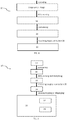
- the control unit 16 may process the digitized positions 14 by inverse-inverse dynamics modeling ( FIG. 15 ).
- inverse-inverse dynamics modeling enables the system 10 to create a fluid model as opposed to a rigid model.
- inverse-inverse dynamics modeling solves the technical problem of simulating how fluid joints and connectors (e.g., inputs 22) of subjects 2 affect a corrective surgery, particularly in instances where a rigid model would generate a model that would result in an undercorrection if implemented in a surgical correction.
- the control unit 16 may contain anatomical modeling software capable of, or configured to, simulate kinematics and muscular and joint loads in the full body for typical activities of a subject 2 and for fundamental human body motions.
- control unit 16 An example of such software is ANYBODY MODELING SYSTEMTM software, available from ANYBODY TECHNOLOGYTM of Aalborg, Denmark, configured to execute the inverse-inverse dynamics modeling.
- the inverse-inverse dynamics model improves the functioning of control unit 16, as inverse-inverse dynamics enables control unit 16 to more accurately simulate the simulated surgical correction's interactions with anatomical properties of subject 2, especially properties specific to that subject 2, such as compensation, muscle elasticity, and joint elasticity.
- control unit 16 may be configured to generate a sagittal curvature profile 34 based on the received digitized positions 14 and inputs 22.
- the profile 34 may be both a sagittal and coronal.
- the control unit 16 may morph (i.e., modify) the model 32 to match the profile 34.
- the musculoskeletal model data may be modified by scaling, adjusting positioning of the one or more vertebral bodies 4, morphing the simulated subject anatomical model 32, or combinations thereof.
- the control unit 16 may be configured to apply logic parameters 36, such as that a subject 2 maintains a center of mass over the ankles; maintains a constant horizontal gaze; stands in a posture where postural muscle energy is minimized; has an arm position matching the patient during imaging (i.e., scaling); has no coronal plane deformity, or any combination of these logic parameters 36.
- the control unit 16 may be configured to compare the calculated, or generated, musculoskeletal model 32 with predetermined musculoskeletal model data levels. Data from the calculated musculoskeletal model 32, such as muscle force data 36 or muscle activation data 38, may be used to calculate the simulated surgical correction 24 and communicated to a user through a display 52.
- the control unit 16 may receive and process compensation values 56. In some embodiments, these values may be stored on the control unit 16.
- the control unit 16 may calculate compensation data 38, for example, hip compensation, ankle joint compensation, knee joint compensation, shoulder compensation, lumbar compensation, thoracic compensation, cervical compensation, or spinal compensation, including ribs and neck, to generate the model 32.
- Including compensation values 56 and/or compensation data 38 is particularly useful in some embodiments of the system 10, as the compensation values 56 and compensation data 38 considers that joints compensate for spinal changes, such as a degenerated spine.
- model 32 may be more accurately the subject's anatomy and compensation.
- the control unit 16 may also store predetermined compensation data 38 that is associated with the predetermined model 20.
- the control unit 16 may also be configured to include a prediction of trunk muscle force 40 output and leg muscle force output 42 in the prediction of the simulated postoperative surgical correction 24.
- the trunk muscle force output may include cervical output, an erector spinae output, multifidi output, an obliques output, semispinalis output, an abdominal muscles output, or any combination thereof.
- the leg muscle force output includes a soleus output, a gastrocnemius output, a hip and knee flexors output, a hip and knee extensors output, a gluteus maximus output, a gluteus minimus output, or any combination thereof. These outputs 42, 44 may be communicated to a user through the display 52.
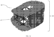
- the simulation of the postoperative surgical correction 24 includes simulating an implant 46 ( FIG. 16 ) in the simulated model 32 of the subject 2.
- a user of the system 10 may select, or design using engineering software, a simulated implant 46 to use in conjunction with the simulated postoperative surgical correction 24.
- the control unit 16 may be configured to receive input from the user for the location, orientation, type, size, and profile of the implant 46.
- the control unit 16 is configured to determine the simulated implant 46 that would achieve optimal posture 18 in the simulated corrective surgery 24. The determination may include the dimensions, location, orientation, type, size, and profile of the implant 46.
- the system 10 may include a three dimensional printer (i.e., an additive manufacturing device or a subtractive manufacturing device) 48 in communication with the control unit 16.
- the three dimensional printer 48 may be configured to create, or partially create, the determined implant 46.
- this feature of the described disclosure allows for personalized surgical implants that are optimized for clinical benefit in the subject 2 to achieve optimized posture 18.
- the control unit 16 may be configured to transmit digital data 50 about the implant 46 for the printer 48 to manufacture the implant 46.
- the implant 46 may be designed on design software executed by the control unit 16 to achieve a desired structure and exported, for example as a STL file, for preparation to be built with the three dimensional printer 48.
- the implant 46 may be designed to have a profile 49 to custom fit the morphology of vertebral body endplates of the subject 2, which may vary from subject to subject.
- the implant manufactured from simulated implant 46 may be constructed of any number, including multiple, suitable biocompatible material, such as titanium, titanium-alloy or stainless steel, surgical steel, or non-metallic compounds such as polymers.
- a system 10 for surgical planning and assessment of spinal deformity correction in a subject 2 includes a spinal imaging device capable of collecting and transmitting to a control unit 16 at least one digitized position 14 of one or more vertebral bodies 4 of the subject 2.
- the control unit 16 is may be configured to receive the at least one digitized position 14 of the one or more vertebral bodies 4 of the subject 2, and calculate, based on morphing and scaling the at least one digitized position 14 onto a predetermined model 20 to form a simulated model 32, an optimized posture 18 for the subject 2.
- the control unit 16 may be configured to execute software including optimization algorithms that tailor the profile of the implant 46 based upon loading conditions imparted upon the implant 46, including: compression, shear, and torsion.
- the control unit 16 may include optimization algorithms that may be executed in order to produce a low-density, material efficient implant 46. This is accomplished by applying multiple, clinically-relevant, loading conditions to the implant 46 in the software program and allowing a finite element solver to optimize and refine, for example, a body lattice structure 47 of the implant 46.
- the system 10 may include a display 52, such as a monitor, in communication with the control unit 16.
- the display 52 may be capable of receiving input from the user in addition to communicating feedback information to the user.
- a graphical user interface 54 GUI is utilized to enter data directly from the screen display 52.
- any given elements of the disclosed embodiments of the invention may be embodied in a single structure, a single step, a single substance, or the like.
- a given element of the disclosed embodiment may be embodied in multiple structures, steps, substances, or the like.
Description
- The present disclosure relates generally to spinal surgery, more specifically to systems and methods relating to the planning, predicting, performing, and assessing of spinal deformity correction and compensatory changes. Such devices as well as systems and methods for use therewith are described.
- The spinal column is a highly complex system of bones and connective tissues that provide support for the body and protect the delicate spinal cord and nerves. The spinal column includes a series of vertebral bodies stack atop one another, each vertebral body including an inner or central portion of relatively weak cancellous bone and an outer portion of relatively strong cortical bone. Situated between each vertebral body is an intervertebral disc that cushions and dampens compressive forces exerted upon the spinal column. A vertebral canal containing the spinal cord is located behind the vertebral bodies. The spine has a natural curvature (i.e., lordosis in the lumbar and cervical regions and kyphosis in the thoracic region) such that the end plates of the upper and lower vertebrae are enclosed toward one another.
- There are many types of spinal column disorders, including scoliosis (abnormal lateral curvature of the spine), excess kyphosis (abnormal forward curvature of the spine), excess lordosis (abnormal backward curvature of the spine), spondylolisthesis (forward displacement of one vertebra over another), and other disorders caused by abnormalities, disease, or trauma (such as ruptured or slipped discs, generative disc disease, fractured vertebrae, and the like).
- Patients that suffer from such conditions often experience extreme and debilitating pain, as well as diminished nerve function. Posterior fixation for spinal fusions, decompression, deformity, and other reconstructions are performed to treat these patients. The aim of posterior fixation in lumbar, thoracic, and cervical procedures is to stabilize the spinal segments, correct multi-axis alignment, and aid in optimizing the long-term health of the spinal cord and nerves.
- Spinal deformity is the result of structural change to the normal alignment of the spine and is usually due to at least one unstable motion segment. The definition and scope of spinal deformity, as well as treatment options, continues to evolve. Surgical objections for spinal deformity correction include curvature correction, prevention of further deformity, improvement or preservation of neurological function, and the restoration of sagittal and coronal balance. Sagittal plane alignment and parameters in cases of adult spinal deformity (ASD) are becoming increasingly recognized as correlative to health related quality of life score (HRQOL). In literature, there are significant correlations between HRQOL scores and radiographic parameters such as Sagittal Vertical Axis (SVA), Pelvic Tilt (PT) and mismatch between pelvic incidence and lumbar lordosis.
- Spinal disorders, such as degenerative processes of the human spine, loss of disc height and lumbar kyphosis, result in a reduced HRQQL. The skeleton compensates for changes in the spine caused by these disorders to maintain balance and horizontal gaze of the subject. However, such compensation requires effort and energy from the subject and is correlated to a lower HRQQL score. Current surgical planning tools do not evaluate or include compensatory changes in a subject, leading to an undercorrection of a deformity in a patient that undergoes the surgical plan and procedure. Therefore, a need continues to exist for systems and methods that include compensatory changes as part of surgical planning.
-
US 2013/131486 describes a computer program for spine mobility simulation to assist in determining a configuration of a spine implant. The computer program simulates the patient's spine and forecasts the impact of changing the position of one or more vertebrae. - The needs described above, as well as others, are addressed by embodiments of a system for spinal correction surgical planning described in this disclosure (although it is to be understood that not all needs described above will necessarily be addressed by any one embodiment), as the system for spinal correction surgical planning of the present disclosure is separable into multiple pieces and can be used in methods, such as surgical planning methods. The systems of the present disclosure may be used, for example, in a method of increasing HRQQL in a subject.
- The present invention provides a system for surgical planning and assessment of spinal deformity correction in a subject as set out in claim 1. Certain optional features of the invention are defined in the dependent claims.
- In an aspect, a system for surgical planning and assessment of spinal deformity correction in a subject is provided. The system includes a spinal imaging system capable of collecting at least one digitized position, such as on a corner, of one or more vertebral bodies of the subject. In an embodiment, digitized positions are from two or more vertebral bodies. The system includes a control unit in communication with the spinal imaging system. The control unit is configured to receive the at least one digitized position of the one or more vertebral bodies. The control unit is configured to calculate, based on the at least one digitized position, an optimized posture for the subject. The calculation of the optimized posture of a subject may include processing a parametric study. The control unit is configured to receive one or more simulated spinal correction inputs, such as sagittal alignment, muscle recruitment criteria, or surgical procedure, such as intervertebral fusion. The control unit is configured to predict a simulated postoperative surgical correction based on the received one or more simulated spinal correction inputs and the received at least one digitized position of the one or more vertebral bodies. The control unit may be configured to determine, or suggest, a surgical plan based on the predicted simulated postoperative surgical correction. The prediction of simulated postoperative surgical correction may be based on one or more values selected from the group consisting of: knee flexion, pelvic retroversion, center of mass migration, ankle flexion, spinal compensation, and a combination thereof.
- In some embodiments of the system, the control unit is configured to communicate the predicted simulated postoperative spinal correction to a user. The control unit may be configured to communicate, or output, a predicted simulated postoperative surgical correction, corresponding to a variance from the calculated optimized posture. The output value of less than 0 may represent a predicted undercorrection, and the output value of greater than 0 may represent an overcorrection. The at least one digitized position of the one or more vertebral bodies may be obtained from X-ray data, computed tomography imaging data, magnetic resonance imaging data, or biplanar X-ray data from the subject. These data may be taken from a patient who is in a lateral standing position.
- In an embodiment of the system, the at least one digitized position is processed by the control unit to generate a musculoskeletal model of the subject. The processing of the at least one digitized position may include inverse-inverse dynamics modeling. The musculoskeletal model may include spinopelvic parameters, ligament parameters, joint kinematics, or any combination thereof. The spinopelvic parameters may include parameters selected from the group consisting of: pelvic tilt, sacral slope, pelvic incidence, sagittal vertical axis, lumbar lordosis, thoracic kyphosis, T1 pelvic angle, and combinations thereof. The musculoskeletal model may include muscle force data or muscle activation data. The control unit may be configured to compare the generated musculoskeletal model with predetermined musculoskeletal model data levels. Data from the generated musculoskeletal model, such as muscle force data or muscle activation data, may be communicated to a user.
- In some embodiments of the system, the control unit is configured to generate a sagittal curvature profile based on the received at least one digitized position of the one or more vertebral bodies. The control unit may be configured to modify the musculoskeletal model data to match the sagittal curvature profile. The musculoskeletal model data may be modified by scaling, adjusting positioning of the one or more vertebral bodies, morphing a simulated subject anatomy, or combinations thereof.
- In an embodiment of the system, the simulated postoperative surgical correction includes hip compensation, knee joint compensation, or ankle joint compensation. The prediction of a simulated postoperative surgical correction may also include a prediction of trunk muscle force output and leg muscle force output. The trunk muscle force output may include an erector spinae output, multifidi output, an obliques output, semispinalis output, an abdominal muscles output, or any combination thereof. The leg muscle force output includes a soleus output, a gastrocnemius output, a hip and knee flexors output, a hip and knee extensors output, a gluteus maximus output, a gluteus minimus output, or any combination thereof.
- In some embodiments of the system, the simulated postoperative surgical correction includes simulating an implant in the subject.
- In another aspect, a system for surgical planning and assessment of spinal deformity correction in a subject includes a spinal imaging system capable of collecting at least one digitized position of one or more vertebral bodies of the subject. The system includes a control unit configured to receive the at least one digitized position of the one or more vertebral bodies of the subject, and calculate, based on morphing and scaling the at least one digitized position onto a model, an optimized posture for the subject.
- In yet another aspect, a system for surgical planning and providing a personalized implant for a subject includes a spinal imaging system capable of collecting at least one digitized position of one or more vertebral bodies of the subject. The system includes a control unit in communication with the spinal imaging system. The control unit is configured to receive the at least one digitized position of the one or more vertebral bodies of the subject to create an initial musculoskeletal model. The control unit is configured to calculate, based on the initial musculoskeletal model, an optimized posture for the subject. The control unit is configured to generate a simulated implant to change the initial musculoskeletal model towards the calculated optimized posture; and communicate dimensional data of the simulated implant to a user. The system may further comprise a three dimension printer configured to create at least part of the simulated implant.
- The above presents a simplified summary in order to provide a basic understanding of some aspects of the claimed subject matter. This summary is not an extensive overview. It is not intended to identify key or critical elements or to delineate the scope of the claimed subject matter. Its sole purpose is to present some concepts in a simplified form as a prelude to the more detailed description that is presented later.
-
-
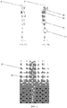
FIG. 1 is a side elevation view of a spine. -
FIG. 2 illustrates a spine of a subject and an X-ray image of a subject. -
FIG. 3 illustrates a spine of a subject. -
FIGS. 4A-4C illustrate various configurations of a spine. -
FIGS. 5A and 5B illustrate a model of a healthy spine and a kyphotic spine, respectively. -
FIG. 6 illustrates a musculoskeletal model in an embodiment of the system. -
FIGS. 7A-7C illustrate bones in a pelvic region of a subject. -
FIG. 8 illustrates steps of generating a musculoskeletal model of a subject according to an embodiment of the system. -
FIG. 9 illustrates steps of generating an output according to one embodiment of the system. -
FIG. 10 illustrates steps of displaying results of a simulated surgical correction according to an embodiment of the system. -
FIG. 11 illustrates steps of displaying results of a simulated surgical correction according to another embodiment of the system. -
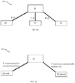
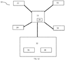
FIG. 12 illustrates an embodiment of the system. -
FIG. 13 illustrates yet another embodiment of the system. -
FIG. 14A illustrates steps for transmitting simulated implant data to an additive or subtractive manufacturing device according to an embodiment of the system. -
FIG. 14B illustrates an embodiment of the system having an additive or subtractive manufacturing device. -
FIG. 15 illustrates steps of inverse-inverse dynamics processing and optimization according to an embodiment of the system. -
FIG. 16 illustrates a simulated implant according to an embodiment of the system. - Illustrative embodiments of a system for surgical planning and assessment of spinal deformity correction are described below. In the interest of clarity, not all features of an actual implementation are described in this specification. It will of course be appreciated that in the development of any such actual embodiment, numerous implementation-specific decisions must be made to achieve the developers' specific goals, such as compliance with system-related and business-related constraints, which will vary from one implementation to another. Moreover, it will be appreciated that such a development effort might be complex and time-consuming, but would nevertheless be a routine undertaking for those of ordinary skill in the art having the benefit of this disclosure. The system for surgical planning and assessment of spinal deformity correction in a subject and related systems and methods disclosed herein boast a variety of inventive features and components that warrant patent protection, both individually and in combination.
- Values given here may be approximate (i.e., +/- 20%, or 10%) such as to account for differences in surgical technique and patient-specific factors.
- In one embodiment, a
system 10 for surgical planning and assessment of spinal deformity correction in asubject 2 includes aspinal imaging system 10 capable, or configured, to collect at least onedigitized position 14 of one or morevertebral bodies 4 of the subject 2, shown inFIG. 1 . It will be appreciated that the present discussion may be applicable to other structures, such as skull bodies and limb joints. Thevertebral bodies 4 may be, for example, cervical, thoracic, lumbar, sacrum, or coccyx. The system 12 includes acontrol unit 16 containing software configured to receive, or collect, thedigitized position 14, as shown in, for example,FIG. 8 . The at least onedigitized position 14 may be any number of positions that correspond to any number of locations, respectively, on the one or morevertebral bodies 4. For example, there may be at least two positions, at least four positions, at least eight positions, at least sixteen positions, or any number of positions therebetween. The at least onedigitized position 14 may correspond to specific locations on the one or morevertebral bodies 4. In one embodiment, thepositions 14 correspond to a corner, or multiple corners, of thevertebral bodies 4, as shown inFIG. 2 . Thecontrol unit 16 may also be configured to collect information of thevertebral bodies 4, such as bone density, fractures, etc. The digitized positions 14 may be extracted from the subject 2 when thesubject 2 is in a standing, lateral position. - The
control unit 16 may collect thedigitized position 14 from any data source of the subject 2 that depicts thevertebral bodies 4 in sufficient detail, including but not limited to, an X-ray image, a computed tomography image, a magnetic resonance imaging image, or biplanar X-ray image of thesubject 2. Thecontrol unit 16 may contain image recognition software whereby thecontrol unit 16 digitizes data provided, such as an X-ray image, a computed tomography image, a magnetic resonance imaging image, or biplanar X-ray image of the subject 2, and thecontrol unit 16 may select digitizedpositions 14 based on output from the image recognition software. The image recognition software, by way of example, may process the image and identify and transmit thepositions 14, such as the corners of the one or morevertebral bodies 4. In some embodiments, this processing and identification is automatic, while in other embodiments, a user manually selects or verifies thepositions 14 from data provided to thecontrol unit 16 such that thecontrol unit 16 receives the digitizedpositions 14 from the user. In yet another embodiment, the digitizedpositions 14 are received digitally from a digital imaging component, such as a digital radiography system. The digitized positions 14 may be displayed usingmedical modeling system 15, such as the archiving and communication system (PACS), shown inFIG. 6 . - In an embodiment of the
system 10, thecontrol unit 16 is configured to calculate, or determine, based on the at least onedigitized position 14, an optimizedposture 18 of thesubject 2. As used herein, "optimized posture" refers to the posture that would be the desired, or ideal, clinical outcome for the subject 2, as for example, determined by a surgeon seeking to perform a spinal correction surgery on the subject 2 who is in need thereof. Thecontrol unit 16 may be configured to calculate the optimizedposture 18 by parametric processing. In parametric processing, data regarding the at least onedigitized position 14 may be compared to one or more predetermined optimizedanatomical posture models 20. The predetermined optimizedanatomical posture models 20 may not be patient-specific. Thepredetermined model 20 selected may be, for example, thepredetermined model 20 that most closely corresponds to the anatomical characteristics of thesubject 2. By way of example, thecontrol unit 16 may be configured to include, or store,predetermined models 20 forsubjects 2 of varying ages, gender and medical conditions (e.g., lordosis, kyphosis, scoliosis), and may select thepredetermined model 20 most suitable for thesubject 2. The at least one anatomicaldigitized positions 14 may be morphed, scaled, or adjusted, either manually or automatically, ontocorresponding points 21 on thepredetermined model 20. As discussed later, thepredetermined model 20 may contain logic, inputs, and parameters for the predicting steps when determining optimized posture and/orsimulated correction 24. - Based on the received at least one
digitized position 14 of the one or morevertebral bodies 4, thecontrol unit 16 is configured to predict, or determine, a simulated postoperative surgical correction 24 (i.e., predict how a surgical correction, such as a posterior lumbar interbody fusion or anterior lumbar interbody fusion, will affect the posture of the subject 2). Thecontrol unit 16 may be configured to determine, for example, the simulated postoperativesurgical correction 24 that would result in, or close to, the optimizedposture 18 for thesubject 2. Based on the simulated postoperativesurgical correction 24, thecontrol unit 16 may be configured to determine, and display to a surgeon, a recommendedsurgical plan 26 to implement the predicted simulated postoperativesurgical correction 24. The recommendedsurgical plan 26 may include, by way of example, information regarding surgical procedure, surgical approach, surgical technique, surgical instrument, and implant. Thecontrol unit 16 may communicate the predicted simulated postoperativespinal correction 24, and/or recommendedsurgical plan 26, to the user. By way of example and as shown inFIG. 9 , thecontrol unit 16 may be configured to communicate, or output, the predicted simulated postoperativesurgical correction 24, corresponding to a variance from the calculated optimizedposture 18. The communicated predicted simulated postoperativespinal correction 24, and/or recommendedsurgical plan 26 may be transmitted as anoutput 28. By way of example, theoutput 28 may be an image representation, a graphical display, or a numerical value. - As illustrated in
FIG. 10 , inembodiments having output 28 as a numerical value, the output value of less than 0 may represent a predictedundercorrection 58 as compared to the optimizedposture 18 and the output value of greater than 0 may represent anovercorrection 62 as compared to the optimizedposture 18. A value of 0 may represent a desired, or optimal,spinal correction 60 that achieves the optimizedposture 18 in thesubject 2. Thus, the value of theoutput 28 may correspond to the variance of the predicted simulated postoperativesurgical correction 24 with the optimizedposture 18, with a higher degree positively correlating with higher variance. As used herein, "undercorrection" means that the predicted simulated postoperativesurgical correction 24 is not able to fully correct the medical condition being corrected of the subject 2, and "overcorrection" means that that the predicted simulated postoperativesurgical correction 24 overly corrects the medical condition being corrected of thesubject 2. The value of theoutput 28 may correspond to any, or any combination, of measurements such as, a value of muscle activation in a patient, a value of kyphosis, a value of lordosis, and a value of Cobb angle. - As described in
FIG. 11 , if the simulated postoperativesurgical correction 24 results in a significant overcorrection or an undercorrection, thesystem 10 may display theoutput 28 in red, such as a red number or a red symbol. On the other hand, if the simulated postoperativesurgical correction 24 results in anoutput 28 equal, or substantially equal, to the corresponding value in the optimizedposture 18, thesystem 10 may display an output in green, such as a green number or a green symbol. Thecontrol unit 16 may be configured to transmit theoutputs 28. Thus, the user (i.e., surgeon) can iteratively change an input plan or input parameters until the goal, such as optimal posture, is achieved. - By way of example, in the case of the subject 2 having Scoliosis, an X-ray image of the subject's 2 spine may be received by the
control unit 16. Thecontrol unit 16 may automatically process the X-ray image to determinedigitized positions 14, such as on points corresponding to corners ofvertebrae bodies 4 of thesubject 2. Using thedigitized positions 14, thecontrol unit 16 may calculate the optimizedposture 18 of thesubject 2. Thecontrol unit 16 may morph and scale the digitizedpositions 14 onto apredetermined model 20 to create asimulated model 32 of the subject's 2 spine. The optimizedposture 18 may have a spine with a Cobb angle of between 0 and 10 degrees, 2 and 8 degrees, or 2 and 6 degrees, or any combination of those values. TheScoliosis subject 2 may have a spinal Cobb of greater than 10 degrees, greater than 15 degrees, greater than 20 degrees, greater than 40 degrees, greater than 50 degrees, or greater than 60 degrees. Thecontrol unit 16 may communicate the Cobb value of the optimizedposture 18 to the user. Thecontrol unit 16 may be configured to receive an inputsurgical correction 30, such as spinal fusion of specific vertebrae, to calculate the predicted simulated postoperativespinal correction 24, and/or recommendedsurgical plan 26. In some embodiments of thesystem 10,multiple plans 26 are recommended. If the optimizedposture 18 has a Cobb angle of 0, and the simulated postoperativespinal correction 24 has a Cobb angle of 0, thecontrol unit 16 would communicate to the user that the inputsurgical correction 30 achieves the optimizedposture 18, such as by returning a value of 0. In contrast, if the optimizedposture 18 has a Cobb angle of 0, and the simulated postoperativespinal correction 24 has a Cobb angle of -5 or +5, thecontrol unit 16 would communicate to the user that the inputsurgical correction 30 results in an undercorrection of -5 or overcorrection of +5, respectively. Of course, the values that represent an undercorrection and overcorrection, such as degree and positivity, may be varied. In some embodiments, thecontrol unit 16 may calculate and determine the predicted simulated postoperativesurgical correction 24 to achieve the Cobb angle of 0 and determine a recommendedsurgical plan 26 that would result in the subject 2 having a Cobb angle of 0. Thecontrol unit 16 may be configured to communicate thesimulated correction 24 and/orplan 26 to the user. - As can be appreciated, the
system 10 may have numerous advantages. For example, thesystem 10 may provide the user with the optimizedposture 18 of thesubject 2. Using the optimizedposture 18, the user may determine the optimalsurgical plan 26 to achieve the optimized posture of thesubject 2. In embodiments of thesystem 10 where thecontrol unit 16 is configured to receive an inputsurgical correction 30 and output asimulated correction 24, thesystem 10 enables the user to remove the uncertainty, or "guesswork," as to the clinical outcome of a surgical correction. Advantageously, this feature of thesystem 10 would provide the user with information, such as whether the proposed surgical correction would result in an undercorrection of the medical condition being treated, that would allow the user to choose the surgical correction that would result in an efficacious clinical outcome for the subject 2 that avoids undercorrection or overcorrection. In embodiments where thesystem 10 predictsoptimal correction 24 and/orplan 26 and communicatescorrection 24 and/orplan 26 to the user, thesystem 10 provides the user with an efficacious surgical correction that a surgeon can implement that avoids undercorrection or overcorrection. Indeed, the describedsystem 10 is a new technological tool for improving surgical outcomes insubjects 2, particularly human subjects in need of and who receive spinal correction surgery. - The
control unit 16 is configured to process various values and factors, as well as contain various logics, to calculate optimizedposture 18 and simulated postoperativesurgical correction 24. For example, thecontrol unit 16 may be configured to receive and process one ormore compensation values 56 selected from the group consisting of: knee flexion, pelvic movement, ankle flexion, shoulder movement, lumbar movement, thoracic movement, cervical movement, spinal compensation, including ribs and neck, and a combination thereof, as shown inFIG. 5B . Thecontrol unit 16 may also be configured to receive and process center ofmass migration 57. Knee flexion refers to joint angle between the bones of the limb at the knee joint. Knee flexion values may be, for example, betweenminus 10 and 150 degrees. Pelvic movement may include pelvic retroversion, pelvic anteversion, and pelvic tilt. Pelvic retroversion may be, for example, less than 50 degrees, less than 30 degrees, less than 25 degrees, less than 20 degrees, less than 15 degrees, less than 10 degrees, less than 5 degrees, or any range thereof. Center ofmass migration 57, as shown inFIG. 3 , refers to the point on the ground over which the mass of the subject 2 is centered, typically the center of mass migrations falls between the ankles of thesubject 2. Ankle flexion refers to a joint angle between the bones of the limb at the ankle joint. These values may be taken from the subject 2 who is in a suitable position, such as standing, supine, and prone. Processing compensation values 56 andmass migration 57 is a technical problem much more difficult than that of processing a rigid skeleton with no compensation (FIG. 5A ) that is overcome by the practicing of the present disclosure. -
FIG. 4A illustrates a non-degenerated spine with the spine in balance.FIG. 4B illustrates a generated spine and retroversion of the pelvis to compensate for the degeneration.FIG. 1C depicts a generated spine and flexion of the knee to compensate for such degeneration. Beneficially, the disclosed system and methods herein can account for these compensations, among other things, to produce a realistic and accurate model for surgical planning. - As shown in
FIG. 12 , thecontrol unit 16 may be configured to generate, or create, amusculoskeletal model 32 of thesubject 2. Thecontrol unit 16 may be configured to compare themodel 32 with thepredetermined model 20 for the control unit's 16 calculation of the optimizedposture 18. Thecontrol unit 16 may receive the digitizedpositions 14 to generate themusculoskeletal model 32 of thesubject 2. Thecontrol unit 16 may also receiveinputs 22, such as spinopelvic parameters, ligament parameters, joint kinematics, sagittal alignment measurements, spinal instability, and muscle recruitment criteria, and intervertebral fusion. As shown inFIGS. 7A-7C , the spinopelvic parameters may include parameters such as pelvic tilt (PT), sacral slope (SS), pelvic incidence (PI), sagittal vertical axis (SVA), lumbar lordosis, thoracic kyphosis, T1 pelvic angle, and combinations thereof. Further, thecontrol unit 16 may input or use global alignment parameters such as global sagittal axis, three-dimensional parameters such as rotation and scoliosis, and cervical parameters. In some embodiments of thesystem 10, the spinopelvic parameters are used to assess, or determine, how far a subject is from a normal or optimum posture. Themodel 32 may also includemuscle 36 force data ormuscle activation data 38. Thecontrol unit 16 may be configured to use theinputs 22 to generate themusculoskeletal model 32 of the subject 2 and optimizedposture 18 of the subject 2, which can include any, or all, of these parameters and inputs that reflect their respective values, or age-adjusted respective values, on themodel 32. Thecontrol unit 16 may be configured to receive theseinputs 22 manually or automatically. Thecontrol unit 16 may use theseinputs 22 to compare and process in comparison to corresponding values on apredetermined model 20 in calculating optimizedposture 18 and simulatedsurgical correction 24.Models - The
control unit 16 may process the digitizedpositions 14 by inverse-inverse dynamics modeling (FIG. 15 ). Advantageously, inverse-inverse dynamics modeling enables thesystem 10 to create a fluid model as opposed to a rigid model. Indeed, inverse-inverse dynamics modeling solves the technical problem of simulating how fluid joints and connectors (e.g., inputs 22) ofsubjects 2 affect a corrective surgery, particularly in instances where a rigid model would generate a model that would result in an undercorrection if implemented in a surgical correction. Thecontrol unit 16 may contain anatomical modeling software capable of, or configured to, simulate kinematics and muscular and joint loads in the full body for typical activities of a subject 2 and for fundamental human body motions. An example of such software is ANYBODY MODELING SYSTEM™ software, available from ANYBODY TECHNOLOGY™ of Aalborg, Denmark, configured to execute the inverse-inverse dynamics modeling. Moreover, the inverse-inverse dynamics model improves the functioning ofcontrol unit 16, as inverse-inverse dynamics enablescontrol unit 16 to more accurately simulate the simulated surgical correction's interactions with anatomical properties ofsubject 2, especially properties specific to thatsubject 2, such as compensation, muscle elasticity, and joint elasticity. - As illustrated in
FIG. 13 , thecontrol unit 16 may be configured to generate asagittal curvature profile 34 based on the receiveddigitized positions 14 andinputs 22. Theprofile 34 may be both a sagittal and coronal. Thecontrol unit 16 may morph (i.e., modify) themodel 32 to match theprofile 34. The musculoskeletal model data may be modified by scaling, adjusting positioning of the one or morevertebral bodies 4, morphing the simulated subjectanatomical model 32, or combinations thereof. - Some, or all, of the
inputs 22 may be predetermined, or manually or automatically received. Thecontrol unit 16 may be configured to applylogic parameters 36, such as that asubject 2 maintains a center of mass over the ankles; maintains a constant horizontal gaze; stands in a posture where postural muscle energy is minimized; has an arm position matching the patient during imaging (i.e., scaling); has no coronal plane deformity, or any combination of theselogic parameters 36. - The
control unit 16 may be configured to compare the calculated, or generated,musculoskeletal model 32 with predetermined musculoskeletal model data levels. Data from the calculatedmusculoskeletal model 32, such asmuscle force data 36 ormuscle activation data 38, may be used to calculate the simulatedsurgical correction 24 and communicated to a user through adisplay 52. - The
control unit 16 may receive and process compensation values 56. In some embodiments, these values may be stored on thecontrol unit 16. Thecontrol unit 16 may calculatecompensation data 38, for example, hip compensation, ankle joint compensation, knee joint compensation, shoulder compensation, lumbar compensation, thoracic compensation, cervical compensation, or spinal compensation, including ribs and neck, to generate themodel 32. Includingcompensation values 56 and/orcompensation data 38 is particularly useful in some embodiments of thesystem 10, as the compensation values 56 andcompensation data 38 considers that joints compensate for spinal changes, such as a degenerated spine. Thus, by including the values anddata model 32 may be more accurately the subject's anatomy and compensation. Thecontrol unit 16 may also storepredetermined compensation data 38 that is associated with thepredetermined model 20. - The
control unit 16 may also be configured to include a prediction oftrunk muscle force 40 output and legmuscle force output 42 in the prediction of the simulated postoperativesurgical correction 24. The trunk muscle force output may include cervical output, an erector spinae output, multifidi output, an obliques output, semispinalis output, an abdominal muscles output, or any combination thereof. The leg muscle force output includes a soleus output, a gastrocnemius output, a hip and knee flexors output, a hip and knee extensors output, a gluteus maximus output, a gluteus minimus output, or any combination thereof. Theseoutputs 42, 44 may be communicated to a user through thedisplay 52. - As shown in
FIG. 14A , in some embodiments of thesystem 10, the simulation of the postoperativesurgical correction 24 includes simulating an implant 46 (FIG. 16 ) in thesimulated model 32 of thesubject 2. For example, a user of thesystem 10 may select, or design using engineering software, asimulated implant 46 to use in conjunction with the simulated postoperativesurgical correction 24. Thecontrol unit 16 may be configured to receive input from the user for the location, orientation, type, size, and profile of theimplant 46. In some embodiments of thesystem 10, thecontrol unit 16 is configured to determine thesimulated implant 46 that would achieveoptimal posture 18 in the simulatedcorrective surgery 24. The determination may include the dimensions, location, orientation, type, size, and profile of theimplant 46. - As illustrated in
FIG. 14B , thesystem 10 may include a three dimensional printer (i.e., an additive manufacturing device or a subtractive manufacturing device) 48 in communication with thecontrol unit 16. The threedimensional printer 48 may be configured to create, or partially create, thedetermined implant 46. Advantageously, this feature of the described disclosure allows for personalized surgical implants that are optimized for clinical benefit in the subject 2 to achieve optimizedposture 18. Thecontrol unit 16 may be configured to transmitdigital data 50 about theimplant 46 for theprinter 48 to manufacture theimplant 46. Theimplant 46 may be designed on design software executed by thecontrol unit 16 to achieve a desired structure and exported, for example as a STL file, for preparation to be built with the threedimensional printer 48. Theimplant 46 may be designed to have aprofile 49 to custom fit the morphology of vertebral body endplates of the subject 2, which may vary from subject to subject. The implant manufactured fromsimulated implant 46 may be constructed of any number, including multiple, suitable biocompatible material, such as titanium, titanium-alloy or stainless steel, surgical steel, or non-metallic compounds such as polymers. - In another aspect, a
system 10 for surgical planning and assessment of spinal deformity correction in asubject 2 includes a spinal imaging device capable of collecting and transmitting to acontrol unit 16 at least onedigitized position 14 of one or morevertebral bodies 4 of thesubject 2. Thecontrol unit 16 is may be configured to receive the at least onedigitized position 14 of the one or morevertebral bodies 4 of the subject 2, and calculate, based on morphing and scaling the at least onedigitized position 14 onto apredetermined model 20 to form asimulated model 32, an optimizedposture 18 for thesubject 2. - The
control unit 16 may be configured to execute software including optimization algorithms that tailor the profile of theimplant 46 based upon loading conditions imparted upon theimplant 46, including: compression, shear, and torsion. Thecontrol unit 16 may include optimization algorithms that may be executed in order to produce a low-density, materialefficient implant 46. This is accomplished by applying multiple, clinically-relevant, loading conditions to theimplant 46 in the software program and allowing a finite element solver to optimize and refine, for example, abody lattice structure 47 of theimplant 46. - The
system 10 may include adisplay 52, such as a monitor, in communication with thecontrol unit 16. Thedisplay 52 may be capable of receiving input from the user in addition to communicating feedback information to the user. By way of example (though it is not a necessity), a graphical user interface 54 (GUI) is utilized to enter data directly from thescreen display 52. - It is to be understood that any given elements of the disclosed embodiments of the invention may be embodied in a single structure, a single step, a single substance, or the like. Similarly, a given element of the disclosed embodiment may be embodied in multiple structures, steps, substances, or the like.
Claims (14)
- A system for surgical planning and assessment of spinal deformity correction in a subject, the system comprising:a spinal imaging system (10) capable of collecting at least one digitized position of one or more vertebral bodies of the subject; anda control unit (16) in communication with the spinal imaging system (10), said control unit being configured to:determine a model of the subject based on the at least one digitized position of the one or more vertebral bodies received from the spinal imaging system, wherein the at least one digitized position of the one or more vertebral bodies corresponds to a standing lateral position of the subject; calculate an optimized posture for the subject based on a comparison of the determined model and one or more predetermined models that correspond to one or more anatomical characteristics of the subject;receive one or more simulated spinal correction inputs, wherein the one or more simulated spinal correction inputs one or more of (i) muscle force data and (ii) muscle activation data;predict a simulated postoperative surgical correction that maintains a center of mass over the ankles of the subject based on the received one or more simulated spinal correction inputs and the calculated optimized posture for the subject; and determine a surgical plan based on the predicted simulated postoperative surgical correction and communicate the determined surgical plan via a display.
- The system of claim 1, wherein the digitized position is on at least one of the corners of the one or more vertebral bodies.
- The system of claim 1, wherein the one or more vertebral bodies includes two or more vertebral bodies.
- The system of claim 1, wherein the control unit (16) is configured to communicate the predicted simulated postoperative spinal correction to a user.
- The system of claim 1, wherein the at least one digitized position is processed to generate a musculoskeletal model of the subject, and the musculoskeletal model includes spinopelvic parameters, ligament parameters, joint kinematics, or any combination thereof.
- The system of claim 5, wherein the control unit (16) is configured to compare the generated musculoskeletal model with predetermined musculoskeletal model data levels.
- The system of claim 5, wherein the control unit (16) is configured to generate a sagittal curvature profile based on the received at least one digitized position of the one or more vertebral bodies.
- The system of claim 7, wherein the control unit (16) is configured to modify the musculoskeletal model to match the sagittal curvature profile.
- The system of claim 8, wherein the modifying of the musculoskeletal model comprises scaling, adjusting positioning of the one or more vertebral bodies, morphing a simulated subject anatomy, or combinations thereof.
- The system of claim 1, wherein the prediction of the simulated postoperative surgical correction comprises a prediction of simulated anterior lumbar interbody fusion surgery.
- The system of claim 1, wherein the prediction of simulated postoperative surgical correction is based on one or more values selected from the group consisting of:
knee flexion, ankle flexion, pelvic retroversion, spinal compensation, and a combination thereof. - The system of claim 1, wherein the one or more simulated spinal correction inputs includes sagittal alignment, muscle recruitment criteria, or a surgical procedure.
- The system of claim 1, wherein the simulated postoperative surgical correction includes hip compensation, knee joint compensation, or ankle joint compensation.
- The system of claim 1, wherein the control unit (16) is configured to output a value, based on the predicted simulated postoperative surgical correction, corresponding to a variance from the calculated optimized posture.
Priority Applications (1)
| Application Number | Priority Date | Filing Date | Title |
|---|---|---|---|
| EP21168383.4A EP3868294B1 (en) | 2016-03-02 | 2017-03-02 | System for spinal correction surgical planning |
Applications Claiming Priority (2)
| Application Number | Priority Date | Filing Date | Title |
|---|---|---|---|
| US201662302725P | 2016-03-02 | 2016-03-02 | |
| PCT/US2017/020491 WO2017151949A1 (en) | 2016-03-02 | 2017-03-02 | Systems and methods for spinal correction surgical planning |
Related Child Applications (2)
| Application Number | Title | Priority Date | Filing Date |
|---|---|---|---|
| EP21168383.4A Division-Into EP3868294B1 (en) | 2016-03-02 | 2017-03-02 | System for spinal correction surgical planning |
| EP21168383.4A Division EP3868294B1 (en) | 2016-03-02 | 2017-03-02 | System for spinal correction surgical planning |
Publications (3)
| Publication Number | Publication Date |
|---|---|
| EP3422940A1 EP3422940A1 (en) | 2019-01-09 |
| EP3422940A4 EP3422940A4 (en) | 2019-10-30 |
| EP3422940B1 true EP3422940B1 (en) | 2021-06-16 |
Family
ID=59723090
Family Applications (2)
| Application Number | Title | Priority Date | Filing Date |
|---|---|---|---|
| EP17760840.3A Active EP3422940B1 (en) | 2016-03-02 | 2017-03-02 | Systems and methods for spinal correction surgical planning |
| EP21168383.4A Active EP3868294B1 (en) | 2016-03-02 | 2017-03-02 | System for spinal correction surgical planning |
Family Applications After (1)
| Application Number | Title | Priority Date | Filing Date |
|---|---|---|---|
| EP21168383.4A Active EP3868294B1 (en) | 2016-03-02 | 2017-03-02 | System for spinal correction surgical planning |
Country Status (8)
| Country | Link |
|---|---|
| US (4) | US10463433B2 (en) |
| EP (2) | EP3422940B1 (en) |
| JP (1) | JP2019514450A (en) |
| AU (2) | AU2017225796B2 (en) |
| BR (1) | BR112018067591B1 (en) |
| ES (1) | ES2877761T3 (en) |
| IL (1) | IL261328B (en) |
| WO (1) | WO2017151949A1 (en) |
Families Citing this family (34)
| Publication number | Priority date | Publication date | Assignee | Title |
|---|---|---|---|---|
| FR3010628B1 (en) | 2013-09-18 | 2015-10-16 | Medicrea International | METHOD FOR REALIZING THE IDEAL CURVATURE OF A ROD OF A VERTEBRAL OSTEOSYNTHESIS EQUIPMENT FOR STRENGTHENING THE VERTEBRAL COLUMN OF A PATIENT |
| FR3012030B1 (en) | 2013-10-18 | 2015-12-25 | Medicrea International | METHOD FOR REALIZING THE IDEAL CURVATURE OF A ROD OF A VERTEBRAL OSTEOSYNTHESIS EQUIPMENT FOR STRENGTHENING THE VERTEBRAL COLUMN OF A PATIENT |
| EP3370657B1 (en) | 2015-11-04 | 2023-12-27 | Medicrea International | Apparatus for spinal reconstructive surgery and measuring spinal length |
| WO2017085529A1 (en) * | 2015-11-19 | 2017-05-26 | Eos Imaging | Method of preoperative planning to correct spine misalignment of a patient |
| EP3422940B1 (en) * | 2016-03-02 | 2021-06-16 | Nuvasive, Inc. | Systems and methods for spinal correction surgical planning |
| WO2018109556A1 (en) | 2016-12-12 | 2018-06-21 | Medicrea International | Systems and methods for patient-specific spinal implants |
| US11185369B2 (en) | 2017-04-21 | 2021-11-30 | Medicrea Nternational | Systems, methods, and devices for developing patient-specific spinal treatments, operations, and procedures |
| EP3651637A4 (en) | 2017-07-12 | 2021-04-28 | K2M, Inc. | Systems and methods for modeling spines and treating spines based on spine models |
| US11166764B2 (en) | 2017-07-27 | 2021-11-09 | Carlsmed, Inc. | Systems and methods for assisting and augmenting surgical procedures |
| US10892058B2 (en) | 2017-09-29 | 2021-01-12 | K2M, Inc. | Systems and methods for simulating spine and skeletal system pathologies |
| US11112770B2 (en) | 2017-11-09 | 2021-09-07 | Carlsmed, Inc. | Systems and methods for assisting a surgeon and producing patient-specific medical devices |
| US10918422B2 (en) | 2017-12-01 | 2021-02-16 | Medicrea International | Method and apparatus for inhibiting proximal junctional failure |
| US11083586B2 (en) * | 2017-12-04 | 2021-08-10 | Carlsmed, Inc. | Systems and methods for multi-planar orthopedic alignment |
| US11432943B2 (en) | 2018-03-14 | 2022-09-06 | Carlsmed, Inc. | Systems and methods for orthopedic implant fixation |
| US11439514B2 (en) | 2018-04-16 | 2022-09-13 | Carlsmed, Inc. | Systems and methods for orthopedic implant fixation |
| USD958151S1 (en) | 2018-07-30 | 2022-07-19 | Carlsmed, Inc. | Display screen with a graphical user interface for surgical planning |
| EP3849453A4 (en) | 2018-09-12 | 2022-07-20 | Carlsmed, Inc. | Systems and methods for orthopedic implants |
| US11636650B2 (en) | 2018-09-24 | 2023-04-25 | K2M, Inc. | System and method for isolating anatomical features in computerized tomography data |
| EP3911261A1 (en) * | 2019-01-14 | 2021-11-24 | Nuvasive, Inc. | Prediction of postoperative global sagittal alignment based on full-body musculoskeletal modeling and posture optimization |
| WO2020201353A1 (en) | 2019-04-02 | 2020-10-08 | Medicrea International | Systems, methods, and devices for developing patient-specific spinal implants, treatments, operations, and/or procedures |
| US11925417B2 (en) | 2019-04-02 | 2024-03-12 | Medicrea International | Systems, methods, and devices for developing patient-specific spinal implants, treatments, operations, and/or procedures |
| DE102019109789A1 (en) * | 2019-04-12 | 2020-10-15 | Fraunhofer-Gesellschaft zur Förderung der angewandten Forschung e.V. | Method and computer program for time-resolved calculation of a deformation of a body |
| EP3958758A4 (en) * | 2019-04-23 | 2022-12-07 | Warsaw Orthopedic, Inc. | Surgical system and method |
| US11791053B2 (en) * | 2019-07-11 | 2023-10-17 | Silicospine Inc. | Method and system for simulating intervertebral disc pathophysiology |
| US11337820B2 (en) * | 2019-09-24 | 2022-05-24 | Samuel Cho | Method, system, and apparatus for producing in interbody implants |
| US11769251B2 (en) | 2019-12-26 | 2023-09-26 | Medicrea International | Systems and methods for medical image analysis |
| US10902944B1 (en) | 2020-01-06 | 2021-01-26 | Carlsmed, Inc. | Patient-specific medical procedures and devices, and associated systems and methods |
| US11376076B2 (en) | 2020-01-06 | 2022-07-05 | Carlsmed, Inc. | Patient-specific medical systems, devices, and methods |
| US11450435B2 (en) | 2020-04-07 | 2022-09-20 | Mazor Robotics Ltd. | Spinal stenosis detection and generation of spinal decompression plan |
| US11426119B2 (en) * | 2020-04-10 | 2022-08-30 | Warsaw Orthopedic, Inc. | Assessment of spinal column integrity |
| CN112316304B (en) * | 2020-12-04 | 2023-04-14 | 郑州大学 | Robust H-infinity repetition control method for wrist tremor suppression |
| US11443838B1 (en) | 2022-02-23 | 2022-09-13 | Carlsmed, Inc. | Non-fungible token systems and methods for storing and accessing healthcare data |
| US11806241B1 (en) | 2022-09-22 | 2023-11-07 | Carlsmed, Inc. | System for manufacturing and pre-operative inspecting of patient-specific implants |
| US11793577B1 (en) | 2023-01-27 | 2023-10-24 | Carlsmed, Inc. | Techniques to map three-dimensional human anatomy data to two-dimensional human anatomy data |
Family Cites Families (347)
| Publication number | Priority date | Publication date | Assignee | Title |
|---|---|---|---|---|
| US2693798A (en) | 1951-04-23 | 1954-11-09 | Edward J Haboush | Device for bending, cutting and extracting the bone nails, nailplates, and the like |
| US3866458A (en) | 1973-11-12 | 1975-02-18 | Richard F Wagner | Bender for contouring surgical implants |
| US4411259A (en) | 1980-02-04 | 1983-10-25 | Drummond Denis S | Apparatus for engaging a hook assembly to a spinal column |
| US4409968A (en) | 1980-02-04 | 1983-10-18 | Drummond Denis S | Method and apparatus for engaging a hook assembly to a spinal column |
| US4474046A (en) | 1982-06-18 | 1984-10-02 | Zimmer, Inc. | Rod bender |
| US4653481A (en) | 1985-07-24 | 1987-03-31 | Howland Robert S | Advanced spine fixation system and method |
| US4773402A (en) | 1985-09-13 | 1988-09-27 | Isola Implants, Inc. | Dorsal transacral surgical implant |
| US4887595A (en) | 1987-07-29 | 1989-12-19 | Acromed Corporation | Surgically implantable device for spinal columns |
| US5099846A (en) | 1988-12-23 | 1992-03-31 | Hardy Tyrone L | Method and apparatus for video presentation from a variety of scanner imaging sources |
| SU1747045A1 (en) | 1989-08-14 | 1992-07-15 | Научно-производственное объединение "Сибцветметавтоматика" | Device for bending correction rods |
| US5290289A (en) | 1990-05-22 | 1994-03-01 | Sanders Albert E | Nitinol spinal instrumentation and method for surgically treating scoliosis |
| JPH0669483B2 (en) | 1991-01-18 | 1994-09-07 | 村中医療器株式会社 | A shape-recovering molding tool that is the prototype of orthopedic investment material |
| US5113685A (en) | 1991-01-28 | 1992-05-19 | Acromed Corporation | Apparatus for contouring spine plates and/or rods |
| JPH0523291A (en) | 1991-07-24 | 1993-02-02 | Machida Endscope Co Ltd | Curved tube of endoscope |
| US5161404A (en) | 1991-10-23 | 1992-11-10 | Zimmer, Inc. | Rod bender |
| US5239716A (en) | 1992-04-03 | 1993-08-31 | Fisk Albert W | Surgical spinal positioning frame |
| GB2267757B (en) | 1992-06-13 | 1996-03-06 | Jeffrey Keith Middleton | Gauge |
| FR2697743B1 (en) | 1992-11-09 | 1995-01-27 | Fabrication Mat Orthopedique S | Spinal osteosynthesis device applicable in particular to degenerative vertebrae. |
| EP0646263B1 (en) | 1993-04-20 | 2000-05-31 | General Electric Company | Computer graphic and live video system for enhancing visualisation of body structures during surgery |
| US5389099A (en) | 1993-07-28 | 1995-02-14 | Hartmeister; Ruben | Keyhole rod bender |
| FR2709246B1 (en) | 1993-08-27 | 1995-09-29 | Martin Jean Raymond | Dynamic implanted spinal orthosis. |
| FR2709248B1 (en) | 1993-08-27 | 1995-09-29 | Martin Jean Raymond | Ancillary equipment for placing a spinal instrumentation. |
| US5548985A (en) | 1994-05-13 | 1996-08-27 | Yapp; Ronald A. | Rod bender for forming surgical implants in the operating room |
| DE9408154U1 (en) | 1994-05-18 | 1994-07-21 | Aesculap Ag | Implantation set |
| WO1998008454A1 (en) | 1994-05-25 | 1998-03-05 | Jackson Roger P | Apparatus and method for spinal fixation and correction of spinal deformities |
| US5765561A (en) | 1994-10-07 | 1998-06-16 | Medical Media Systems | Video-based surgical targeting system |
| US5490409A (en) | 1994-11-07 | 1996-02-13 | K-Medic, Inc. | Adjustable cam action rod bender for surgical rods |
| DE29510041U1 (en) | 1995-06-21 | 1995-09-07 | Elekta Instr Ab | Device for forming thin flat workpieces |
| US5564302A (en) | 1995-07-11 | 1996-10-15 | Watrous; Willis G. | Orthopedic bone plate bending irons |
| US5658286A (en) | 1996-02-05 | 1997-08-19 | Sava; Garard A. | Fabrication of implantable bone fixation elements |
| US5799055A (en) | 1996-05-15 | 1998-08-25 | Northwestern University | Apparatus and method for planning a stereotactic surgical procedure using coordinated fluoroscopy |
| DE29609276U1 (en) | 1996-05-23 | 1996-08-14 | Aesculap Ag | Surgical bending device |
| US8083745B2 (en) | 2001-05-25 | 2011-12-27 | Conformis, Inc. | Surgical tools for arthroplasty |
| US8556983B2 (en) | 2001-05-25 | 2013-10-15 | Conformis, Inc. | Patient-adapted and improved orthopedic implants, designs and related tools |
| US20110071802A1 (en) | 2009-02-25 | 2011-03-24 | Ray Bojarski | Patient-adapted and improved articular implants, designs and related guide tools |
| US5819571A (en) | 1997-02-10 | 1998-10-13 | Johnson; Stephen | Apparatus for bending surgical instruments |
| US5880976A (en) | 1997-02-21 | 1999-03-09 | Carnegie Mellon University | Apparatus and method for facilitating the implantation of artificial components in joints |
| US6205411B1 (en) | 1997-02-21 | 2001-03-20 | Carnegie Mellon University | Computer-assisted surgery planner and intra-operative guidance system |
| US6175758B1 (en) | 1997-07-15 | 2001-01-16 | Parviz Kambin | Method for percutaneous arthroscopic disc removal, bone biopsy and fixation of the vertebrae |
| US6226548B1 (en) | 1997-09-24 | 2001-05-01 | Surgical Navigation Technologies, Inc. | Percutaneous registration apparatus and method for use in computer-assisted surgical navigation |
| USD415665S (en) | 1997-09-30 | 1999-10-26 | Somnus Medical Technologies Inc. | Bending tool |
| DE59711387D1 (en) | 1997-11-21 | 2004-04-08 | Synthes Ag | DEVICE FOR SIMULATING IMPLANTS POSITIONED UNDER THE SKIN |
| US5819580A (en) | 1998-04-13 | 1998-10-13 | Beere Precision Medical Instruments, Inc. | Bending tool |
| US6529765B1 (en) | 1998-04-21 | 2003-03-04 | Neutar L.L.C. | Instrumented and actuated guidance fixture for sterotactic surgery |
| US6024759A (en) | 1998-05-08 | 2000-02-15 | Walter Lorenz Surgical, Inc. | Method and apparatus for performing pectus excavatum repair |
| US6327491B1 (en) | 1998-07-06 | 2001-12-04 | Neutar, Llc | Customized surgical fixture |
| US6264658B1 (en) | 1998-07-06 | 2001-07-24 | Solco Surgical Instruments Co., Ltd. | Spine fixing apparatus |
| US6006581A (en) | 1998-10-26 | 1999-12-28 | Hol-Med Corporation | Rod bending system |
| US6285902B1 (en) | 1999-02-10 | 2001-09-04 | Surgical Insights, Inc. | Computer assisted targeting device for use in orthopaedic surgery |
| CA2591678C (en) | 1999-03-07 | 2008-05-20 | Active Implants Corporation | Method and apparatus for computerized surgery |
| US6128944A (en) | 1999-04-06 | 2000-10-10 | Haynes; Alvin | Apparatus for bending malleable metal rods |
| US6035691A (en) | 1999-08-10 | 2000-03-14 | Lin; Ruey-Mo | Adjustable rod bending device for a corrective spinal rod which is used in a surgical operation |
| FR2803756B1 (en) | 2000-01-18 | 2004-11-26 | Eurosurgical | CONNECTING ROD FOR SPINAL INSTRUMENTATION |
| US6701174B1 (en) | 2000-04-07 | 2004-03-02 | Carnegie Mellon University | Computer-aided bone distraction |
| US20040068187A1 (en) | 2000-04-07 | 2004-04-08 | Krause Norman M. | Computer-aided orthopedic surgery |
| US6711432B1 (en) | 2000-10-23 | 2004-03-23 | Carnegie Mellon University | Computer-aided orthopedic surgery |
| FR2816200A1 (en) | 2000-11-06 | 2002-05-10 | Praxim | DETERMINING THE POSITION OF A KNEE PROSTHESIS |
| US20030055435A1 (en) | 2000-11-27 | 2003-03-20 | Barrick Earl Frederick | Orthopaedic implant shaper |
| WO2002096268A2 (en) | 2001-05-25 | 2002-12-05 | Imaging Therapeutics, Inc. | Methods and compositions for articular resurfacing |
| US9308091B2 (en) | 2001-05-25 | 2016-04-12 | Conformis, Inc. | Devices and methods for treatment of facet and other joints |
| SE0104323D0 (en) | 2001-12-20 | 2001-12-20 | Matts Andersson | Method and arrangement of implants for preferably human intermediate disc and such implant |
| US7634306B2 (en) | 2002-02-13 | 2009-12-15 | Kinamed, Inc. | Non-image, computer assisted navigation system for joint replacement surgery with modular implant system |
| FR2836818B1 (en) | 2002-03-05 | 2004-07-02 | Eurosurgical | PROCESS FOR VISUALIZING AND CHECKING THE BALANCE OF A SPINE COLUMN |
| US6638281B2 (en) | 2002-03-21 | 2003-10-28 | Spinecore, Inc. | Gravity dependent pedicle screw tap hole guide |
| US20040144149A1 (en) | 2002-05-02 | 2004-07-29 | Walter Strippgen | Non-marring spinal rod curving instrument and method for using same |
| US6644087B1 (en) | 2002-07-26 | 2003-11-11 | Third Millennium Engineering, Llc | Rod bender for bending surgical rods |
| US20040044295A1 (en) | 2002-08-19 | 2004-03-04 | Orthosoft Inc. | Graphical user interface for computer-assisted surgery |
| AU2003257339A1 (en) | 2002-08-26 | 2004-03-11 | Orthosoft Inc. | Computer aided surgery system and method for placing multiple implants |
| GB2393625C (en) | 2002-09-26 | 2004-08-18 | Meridian Tech Ltd | Orthopaedic surgery planning |
| EP3075356B1 (en) | 2002-11-07 | 2023-07-05 | ConforMIS, Inc. | Method of selecting a meniscal implant |
| ES2522972T3 (en) | 2002-12-23 | 2014-11-19 | F.Hoffmann-La Roche Ag | Device for testing body fluids |
| US7660623B2 (en) | 2003-01-30 | 2010-02-09 | Medtronic Navigation, Inc. | Six degree of freedom alignment display for medical procedures |
| US20050043660A1 (en) * | 2003-03-31 | 2005-02-24 | Izex Technologies, Inc. | Orthoses |
| DE102004008870A1 (en) | 2003-03-31 | 2004-10-14 | Anders, Peter, Prof. Dr.-Ing. | Bending method for a workpiece such as a rod or tube for use in e.g. spinal surgery where a target curve is defined about which the rod is bent |
| DE10314882A1 (en) | 2003-04-01 | 2004-10-14 | Anders, Peter, Prof. Dr.-Ing. | Bending procedure for rod used in operatively treating scoliosis, by determining space curve or target curve using navigation system which dismantles the curve into part curves from which the bending of the rod takes place |
| US10588629B2 (en) | 2009-11-20 | 2020-03-17 | Covidien Lp | Surgical console and hand-held surgical device |
| US20050262911A1 (en) | 2004-02-06 | 2005-12-01 | Harry Dankowicz | Computer-aided three-dimensional bending of spinal rod implants, other surgical implants and other articles, systems for three-dimensional shaping, and apparatuses therefor |
| KR101149094B1 (en) | 2004-02-20 | 2012-05-25 | 헥터 오. 파체코 | Method for improving pedicle screw placement |
| US20050203511A1 (en) | 2004-03-02 | 2005-09-15 | Wilson-Macdonald James | Orthopaedics device and system |
| WO2005087125A2 (en) | 2004-03-10 | 2005-09-22 | Depuy International Ltd | Orthopaedic operating systems, methods, implants and instruments |
| US7567834B2 (en) | 2004-05-03 | 2009-07-28 | Medtronic Navigation, Inc. | Method and apparatus for implantation between two vertebral bodies |
| US7340316B2 (en) | 2004-06-28 | 2008-03-04 | Hanger Orthopedic Group, Inc. | System and method for producing medical devices |
| US7346382B2 (en) * | 2004-07-07 | 2008-03-18 | The Cleveland Clinic Foundation | Brain stimulation models, systems, devices, and methods |
| US8180601B2 (en) * | 2006-03-09 | 2012-05-15 | The Cleveland Clinic Foundation | Systems and methods for determining volume of activation for deep brain stimulation |
| US20060082015A1 (en) | 2004-09-30 | 2006-04-20 | Inion Ltd. | Surgical implant shaping instrument, surgical system and method |
| US20090226055A1 (en) | 2004-12-10 | 2009-09-10 | Harry Dankowicz | Systems and methods for multi-dimensional characterization and classification of spinal shape |
| US20060212158A1 (en) | 2004-12-23 | 2006-09-21 | Robert Miller | System for manufacturing an implant |
| US7454939B2 (en) | 2005-01-12 | 2008-11-25 | Depuy Spine, Inc. | Instrument for bending spinal rods used in a spinal fixation system |
| ES2784219T3 (en) | 2005-03-07 | 2020-09-23 | Hector O Pacheco | Cannula for improved access to vertebral bodies for kyphoplasty, vertebroplasty, vertebral body biopsy or screw placement |
| US20100100011A1 (en) | 2008-10-22 | 2010-04-22 | Martin Roche | System and Method for Orthopedic Alignment and Measurement |
| US8668699B2 (en) | 2005-04-14 | 2014-03-11 | Warsaw Orthopedic, Inc. | Multi-function orthopedic instrument |
| US7488331B2 (en) | 2005-05-23 | 2009-02-10 | Custon Spine, Inc. | Orthopedic implant bender |
| KR101258912B1 (en) | 2005-06-06 | 2013-04-30 | 인튜어티브 서지컬 인코포레이티드 | Laparoscopic ultrasound robotic surgical system |
| DE102005029165B4 (en) | 2005-06-23 | 2009-01-22 | Stryker Leibinger Gmbh & Co. Kg | Bending pliers and bending forceps system for surgical elements |
| CA2616002A1 (en) | 2005-07-22 | 2007-01-25 | Cedera Software Corp. | Implant inventory management system and method using digital image planning |
| US7643862B2 (en) | 2005-09-15 | 2010-01-05 | Biomet Manufacturing Corporation | Virtual mouse for use in surgical navigation |
| US20070118055A1 (en) | 2005-11-04 | 2007-05-24 | Smith & Nephew, Inc. | Systems and methods for facilitating surgical procedures involving custom medical implants |
| CN200966629Y (en) | 2005-12-31 | 2007-10-31 | 周兵 | Deplane angle type sucking tube and the free pipe bender |
| JP4826459B2 (en) * | 2006-01-12 | 2011-11-30 | 株式会社豊田中央研究所 | Musculoskeletal model creation method, human stress / strain estimation method, program, and recording medium |
| US20070174769A1 (en) | 2006-01-24 | 2007-07-26 | Sdgi Holdings, Inc. | System and method of mapping images of the spine |
| US8894655B2 (en) | 2006-02-06 | 2014-11-25 | Stryker Spine | Rod contouring apparatus and method for percutaneous pedicle screw extension |
| US8177843B2 (en) | 2006-02-16 | 2012-05-15 | Nabil L. Muhanna | Automated pedicle screw rod bender |
| JP2007283081A (en) | 2006-03-23 | 2007-11-01 | Makoto Kobori | Bending device for spinal column fixing member |
| US20070269544A1 (en) | 2006-03-29 | 2007-11-22 | Sdgi Holdings, Inc. | Devices and methods for contouring a shape of an implant that is positioned within a patient |
| CN2885154Y (en) | 2006-03-30 | 2007-04-04 | 费新昌 | A medical bending device |
| WO2007136784A2 (en) | 2006-05-17 | 2007-11-29 | Nuvasive, Inc. | Surgical trajectory monitoring system and related methods |
| CN101478913B (en) | 2006-06-28 | 2010-12-01 | 赫克托·O·帕切科 | Apparatus and methods for templating and placement of artificial discs |
| US8565853B2 (en) | 2006-08-11 | 2013-10-22 | DePuy Synthes Products, LLC | Simulated bone or tissue manipulation |
| WO2008038282A2 (en) | 2006-09-25 | 2008-04-03 | Mazor Surgical Technologies Ltd. | System for positioning of surgical inserts and tools |
| US20080103500A1 (en) | 2006-10-31 | 2008-05-01 | Nam Chao | Instruments and Methods For Smoothing A Portion of A Spinal Rod |
| FR2909791B1 (en) | 2006-12-07 | 2009-02-13 | Ecole Nale Sup Artes Metiers | METHOD FOR SIMULATING THE BEHAVIOR OF AN ARTICULATED BONE ASSEMBLY |
| US20080177203A1 (en) | 2006-12-22 | 2008-07-24 | General Electric Company | Surgical navigation planning system and method for placement of percutaneous instrumentation and implants |
| US20080161680A1 (en) | 2006-12-29 | 2008-07-03 | General Electric Company | System and method for surgical navigation of motion preservation prosthesis |
| WO2008087629A2 (en) | 2007-01-16 | 2008-07-24 | Simbionix Ltd. | Preoperative surgical simulation |
| US8374673B2 (en) | 2007-01-25 | 2013-02-12 | Warsaw Orthopedic, Inc. | Integrated surgical navigational and neuromonitoring system having automated surgical assistance and control |
| DE102007010806B4 (en) | 2007-03-02 | 2010-05-12 | Siemens Ag | A method of providing advanced capabilities in the use of patient image data and radiographic angiography system unsuitable for use in registration procedures |
| US8255045B2 (en) * | 2007-04-03 | 2012-08-28 | Nuvasive, Inc. | Neurophysiologic monitoring system |
| AU2007351804B2 (en) | 2007-04-19 | 2013-09-05 | Mako Surgical Corp. | Implant planning using captured joint motion information |
| WO2008157813A1 (en) | 2007-06-20 | 2008-12-24 | Surgmatix, Inc. | Surgical data monitoring and display system |
| US20090024164A1 (en) | 2007-06-25 | 2009-01-22 | Neubardt Seth L | System for determining spinal implants |
| EP2162067B1 (en) | 2007-07-04 | 2019-09-11 | EOS Imaging | Method for correcting an acquired medical image and medical imager |
| EP2017785A1 (en) | 2007-07-17 | 2009-01-21 | BrainLAB AG | Imaging method for motion analysis |
| DE102007033219B4 (en) | 2007-07-17 | 2010-10-07 | Aesculap Ag | Orthopedic retention system |
| PT103823B (en) | 2007-09-13 | 2010-09-17 | Univ Do Minho | AUTOMATIC AND CUSTOMIZED SURGICAL PROSTATE MODELING / BENDING SYSTEM FOR CORRECTION OF PECTUS EXCAVATUM BASED ON PRE-SURGICAL IMAGIOLOGICAL INFORMATION |
| US8101116B2 (en) | 2007-09-19 | 2012-01-24 | Ethicon, Inc. | Preformed support device and method and apparatus for manufacturing the same |
| WO2009039371A1 (en) | 2007-09-19 | 2009-03-26 | Ethicon, Inc. | Performed support device and method and apparatus for manufacturing the same |
| CA2701811A1 (en) | 2007-11-07 | 2009-05-14 | Alcon Research, Ltd. | Surgical console information display system and method |
| US10582934B2 (en) | 2007-11-27 | 2020-03-10 | Howmedica Osteonics Corporation | Generating MRI images usable for the creation of 3D bone models employed to make customized arthroplasty jigs |
| US8221430B2 (en) | 2007-12-18 | 2012-07-17 | Otismed Corporation | System and method for manufacturing arthroplasty jigs |
| US8715291B2 (en) | 2007-12-18 | 2014-05-06 | Otismed Corporation | Arthroplasty system and related methods |
| US10687856B2 (en) | 2007-12-18 | 2020-06-23 | Howmedica Osteonics Corporation | System and method for image segmentation, bone model generation and modification, and surgical planning |
| US9962166B1 (en) | 2008-02-12 | 2018-05-08 | David P. Sachs | Method and apparatus for performing a surgical operation on the cervical portion of the spine |
| GB0803514D0 (en) | 2008-02-27 | 2008-04-02 | Depuy Int Ltd | Customised surgical apparatus |
| WO2009111626A2 (en) | 2008-03-05 | 2009-09-11 | Conformis, Inc. | Implants for altering wear patterns of articular surfaces |
| US7957831B2 (en) | 2008-04-04 | 2011-06-07 | Isaacs Robert E | System and device for designing and forming a surgical implant |
| US20090254097A1 (en) | 2008-04-04 | 2009-10-08 | Isaacs Robert E | System and device for designing and forming a surgical implant |
| US8549888B2 (en) | 2008-04-04 | 2013-10-08 | Nuvasive, Inc. | System and device for designing and forming a surgical implant |
| ES2580175T3 (en) * | 2008-05-15 | 2016-08-19 | Intelect Medical Inc. | Clinical programmer system and procedure to direct activation volumes |
| EP2468201B1 (en) | 2008-08-12 | 2014-10-08 | Biedermann Technologies GmbH & Co. KG | Flexible stabilization device including a rod and tool for manufacturing the rod |
| US20100183201A1 (en) | 2008-09-18 | 2010-07-22 | Frank Johan Schwab | Adaptive Software and Hardware System for Scientific Image Processsing |
| US8078440B2 (en) | 2008-09-19 | 2011-12-13 | Smith & Nephew, Inc. | Operatively tuning implants for increased performance |
| US20100101295A1 (en) | 2008-10-28 | 2010-04-29 | Warsaw Orthopedic, Inc. | Isulated sheath for bending polymer-based rod |
| US20100111631A1 (en) | 2008-10-31 | 2010-05-06 | Warsaw Orthopedic, Inc. | Tool for Finishing the Ends of Surgical Rods and Methods of Use |
| CN102300512B (en) | 2008-12-01 | 2016-01-20 | 马佐尔机器人有限公司 | The sloped-spine stabilisation that robot guides |
| US8126736B2 (en) * | 2009-01-23 | 2012-02-28 | Warsaw Orthopedic, Inc. | Methods and systems for diagnosing, treating, or tracking spinal disorders |
| US20100191100A1 (en) | 2009-01-23 | 2010-07-29 | Warsaw Orthopedic, Inc. | Methods and systems for diagnosing, treating, or tracking spinal disorders |
| US8170641B2 (en) | 2009-02-20 | 2012-05-01 | Biomet Manufacturing Corp. | Method of imaging an extremity of a patient |
| EP2400921A4 (en) | 2009-02-25 | 2015-11-25 | Zimmer Inc | Customized orthopaedic implants and related methods |
| US20100268119A1 (en) | 2009-04-15 | 2010-10-21 | Warsaw Orthopedic, Inc., An Indiana Corporation | Integrated feedback for in-situ surgical device |
| US8457930B2 (en) | 2009-04-15 | 2013-06-04 | James Schroeder | Personalized fit and functional designed medical prostheses and surgical instruments and methods for making |
| US8235998B2 (en) | 2009-08-17 | 2012-08-07 | Warsaw Orthopedic, Inc. | Instruments and methods for in situ bending of an elongate spinal implant |
| US20110054870A1 (en) * | 2009-09-02 | 2011-03-03 | Honda Motor Co., Ltd. | Vision Based Human Activity Recognition and Monitoring System for Guided Virtual Rehabilitation |
| DE102009047781B4 (en) | 2009-09-30 | 2011-06-09 | Hans Weigum | Device for processing rod-shaped elements |
| KR101606097B1 (en) | 2009-10-01 | 2016-03-24 | 마코 서지컬 코포레이션 | Surgical system for positioning prosthetic component andor for constraining movement of surgical tool |
| US8506603B2 (en) | 2009-10-14 | 2013-08-13 | K2M, Inc. | Surgical rod scorer and method of use of the same |
| US9144447B2 (en) | 2009-10-14 | 2015-09-29 | K2M, Inc. | Surgical rod scorer and method of use of the same |
| EP2488110B8 (en) | 2009-10-14 | 2017-10-25 | K2M, Inc. | Surgical rod scorer and method of use of the same |
| US8827986B2 (en) * | 2009-10-19 | 2014-09-09 | Pharmaco-Kinesis Corporation | Remotely activated piezoelectric pump for delivery of biological agents to the intervertebral disc and spine |
| CN102647962A (en) | 2009-11-24 | 2012-08-22 | 株式会社力克赛 | Preoperative planning program for artificial hip joint replacement surgery and surgery support jig |
| GB0922640D0 (en) | 2009-12-29 | 2010-02-10 | Mobelife Nv | Customized surgical guides, methods for manufacturing and uses thereof |
| EP2528504B1 (en) | 2010-01-28 | 2018-08-15 | Illés, Tamás | A method and a system for multi-dimensional visualization of the spinal column by vertebra vectors, sacrum vector, sacrum plateau vector and pelvis vectors |
| CN102770093B (en) | 2010-02-26 | 2015-10-07 | 思邦科技脊柱智慧集团股份公司 | For computer program and the spinal column analogy method of the simulation of spinal column mobility |
| US20110245871A1 (en) | 2010-04-06 | 2011-10-06 | Williams Lytton A | Crosslink element and bender for spine surgery procedures |
| CA2797302C (en) | 2010-04-28 | 2019-01-15 | Ryerson University | System and methods for intraoperative guidance feedback |
| US8298242B2 (en) | 2010-04-30 | 2012-10-30 | Warsaw Orthopedic, Inc. | Systems, devices and methods for bending an elongate member |
| US8607603B2 (en) | 2010-04-30 | 2013-12-17 | Warsaw Orthopedic, Inc. | Systems, devices and methods for multi-dimensional bending of an elongate member |
| JP5830090B2 (en) * | 2010-06-14 | 2015-12-09 | ボストン サイエンティフィック ニューロモデュレイション コーポレイション | Programming interface for spinal nerve regulation |
| US8862237B2 (en) * | 2010-06-14 | 2014-10-14 | Boston Scientific Neuromodulation Corporation | Programming interface for spinal cord neuromodulation |
| EP2584982B1 (en) | 2010-06-28 | 2019-07-24 | K2M, Inc. | Spinal stabilization system |
| US11376073B2 (en) | 2010-06-29 | 2022-07-05 | Mighty Oak Medical Inc. | Patient-matched apparatus and methods for performing surgical procedures |
| AU2011276468C1 (en) | 2010-06-29 | 2014-09-25 | George Frey | Patient matching surgical guide and method for using the same |
| US8870889B2 (en) * | 2010-06-29 | 2014-10-28 | George Frey | Patient matching surgical guide and method for using the same |
| US9642633B2 (en) | 2010-06-29 | 2017-05-09 | Mighty Oak Medical, Inc. | Patient-matched apparatus and methods for performing surgical procedures |
| KR101818682B1 (en) | 2010-07-08 | 2018-01-16 | 신세스 게엠바하 | Advanced bone marker and custom implants |
| US20120035507A1 (en) | 2010-07-22 | 2012-02-09 | Ivan George | Device and method for measuring anatomic geometries |
| DE102010033116A1 (en) | 2010-08-02 | 2012-02-02 | Siemens Aktiengesellschaft | Method for generating three-dimensional image data, involves performing mutual image registration of three-dimensional image data in overlap region and merging visual three-dimensional single-registered image data |
| FR2964030B1 (en) | 2010-08-25 | 2012-09-28 | Axs Ingenierie | METHOD AND DEVICE FOR DYNAMIC DETERMINATION OF THE POSITION AND ORIENTATION OF BONE ELEMENTS OF THE RACHIS |
| US8770006B2 (en) | 2010-08-26 | 2014-07-08 | Globus Medical, Inc. | Compound hinged rod bender |
| US9785246B2 (en) * | 2010-10-06 | 2017-10-10 | Nuvasive, Inc. | Imaging system and method for use in surgical and interventional medical procedures |
| US8718346B2 (en) * | 2011-10-05 | 2014-05-06 | Saferay Spine Llc | Imaging system and method for use in surgical and interventional medical procedures |
| US11231787B2 (en) * | 2010-10-06 | 2022-01-25 | Nuvasive, Inc. | Imaging system and method for use in surgical and interventional medical procedures |
| US9717508B2 (en) | 2010-10-29 | 2017-08-01 | The Cleveland Clinic Foundation | System of preoperative planning and provision of patient-specific surgical aids |
| WO2012062464A1 (en) | 2010-11-10 | 2012-05-18 | Spontech Spine Intelligence Group Ag | Spine fixation installation system |
| BE1019572A5 (en) | 2010-11-10 | 2012-08-07 | Materialise Nv | OPTIMIZED METHODS FOR THE PRODUCTION OF PATIENT-SPECIFIC MEDICAL TOOLS. |
| US9211145B2 (en) * | 2010-11-29 | 2015-12-15 | Javier Pereiro de Lamo | Method and system for the treatment of spinal deformities |
| EP3150113A1 (en) | 2010-12-13 | 2017-04-05 | Ortho Kinematics, Inc. | Methods, systems and devices for clinical data reporting and surgical navigation |
| US20120186411A1 (en) | 2011-01-25 | 2012-07-26 | Sebstian Lodahi | Automated surgical rod cutter and bender including a power-base, assembly for rod cutting, and assembly for rod bending |
| WO2012100825A1 (en) | 2011-01-26 | 2012-08-02 | Brainlab Ag | Method for planning the positioning of an implant |
| CN107126256B (en) | 2011-02-25 | 2021-01-08 | 科瑞恩公司 | Method comprising computer-implemented steps for providing alignment information data |
| US9788905B2 (en) | 2011-03-30 | 2017-10-17 | Surgical Theater LLC | Method and system for simulating surgical procedures |
| DE102011006574B4 (en) | 2011-03-31 | 2014-11-27 | Siemens Aktiengesellschaft | Method and system for supporting the workflow in an operational environment |
| US9003859B2 (en) | 2011-04-01 | 2015-04-14 | University of Alaska Anchorage | Bending instrument and methods of using same |
| KR101247165B1 (en) | 2011-04-05 | 2013-03-25 | 전남대학교산학협력단 | Therapeutic Microrobot System for Brain and Spinal Cord Diseases |
| US8830233B2 (en) | 2011-04-28 | 2014-09-09 | Howmedica Osteonics Corp. | Surgical case planning platform |
| EP2522295A1 (en) | 2011-05-10 | 2012-11-14 | Loran S.r.l. | Vitual platform for pre-surgery simulation and relative bio-mechanic validation of prothesis surgery of the lumbo-sacral area of the human spine |
| FR2975583B1 (en) | 2011-05-27 | 2014-02-28 | Iceram | BENDERS OR TORDS-BARS USED IN A SPINACH OPERATION |
| CN108992169B (en) * | 2011-07-20 | 2022-10-28 | 史密夫和内修有限公司 | System and method for optimizing fit of implant to anatomy |
| CN202161397U (en) | 2011-07-29 | 2012-03-14 | 中国人民解放军第四军医大学 | Novel titanium bar shaping device |
| US9066734B2 (en) | 2011-08-31 | 2015-06-30 | Biomet Manufacturing, Llc | Patient-specific sacroiliac guides and associated methods |
| US9295497B2 (en) | 2011-08-31 | 2016-03-29 | Biomet Manufacturing, Llc | Patient-specific sacroiliac and pedicle guides |
| US20130072982A1 (en) | 2011-09-19 | 2013-03-21 | Peter Melott Simonson | Spinal assembly load gauge |
| AU2012315809B2 (en) | 2011-09-29 | 2017-06-08 | Arthromeda, Inc. | System and method for precise prosthesis positioning in hip arthroplasty |
| US8459090B2 (en) | 2011-10-13 | 2013-06-11 | Warsaw Orthopedic, Inc. | Rod benders and methods of use |
| US9526535B2 (en) | 2011-11-07 | 2016-12-27 | Morgan Packard Lorio | Methods and apparatuses for delivering a rod to a plurality of pedicle screws |
| DE102011118719A1 (en) | 2011-11-16 | 2013-05-16 | Brabender Gmbh & Co.Kg | Apparatus for extruding a medical instrument insertable into a human or animal body |
| CA3082418C (en) | 2011-12-05 | 2024-01-16 | Dignity Health | Surgical rod bending system and method |
| US9877847B2 (en) | 2012-02-29 | 2018-01-30 | Smith & Nephew, Inc. | Determining anatomical orientations |
| US11207132B2 (en) * | 2012-03-12 | 2021-12-28 | Nuvasive, Inc. | Systems and methods for performing spinal surgery |
| FR2988583B1 (en) | 2012-04-02 | 2014-03-14 | Safe Orthopaedics | CAM BENDER |
| CN104244800B (en) | 2012-04-19 | 2017-05-17 | 皇家飞利浦有限公司 | Guidance tools to manually steer endoscope using pre-operative and intra-operative 3d images |
| JP5932468B2 (en) | 2012-04-27 | 2016-06-08 | メドトロニックソファモアダネック株式会社 | Bender coupling mechanism and vendor equipment |
| US20130296954A1 (en) | 2012-05-02 | 2013-11-07 | Warsaw Orthopedic, Inc. | Surgical tool for bending a rod |
| US9125556B2 (en) | 2012-05-14 | 2015-09-08 | Mazor Robotics Ltd. | Robotic guided endoscope |
| WO2013172940A1 (en) | 2012-05-14 | 2013-11-21 | DePuy Synthes Products, LLC | Cutting/bending tool for polymer implant |
| WO2013175471A1 (en) | 2012-05-22 | 2013-11-28 | Mazor Robotics Ltd. | On-site verification of implant positioning |
| US10350013B2 (en) | 2012-06-21 | 2019-07-16 | Globus Medical, Inc. | Surgical tool systems and methods |
| US20130345757A1 (en) | 2012-06-22 | 2013-12-26 | Shawn D. Stad | Image Guided Intra-Operative Contouring Aid |
| CA2878861A1 (en) | 2012-07-12 | 2014-01-16 | Ao Technology Ag | Method for generating a graphical 3d computer model of at least one anatomical structure in a selectable pre-, intra-, or postoperative status |
| CN104661607A (en) | 2012-07-24 | 2015-05-27 | 卡波菲克斯整形有限责任公司 | Spine system and kit |
| EP4218647A1 (en) | 2012-08-08 | 2023-08-02 | Ortoma AB | System for computer assisted surgery |
| US9622785B2 (en) | 2012-09-04 | 2017-04-18 | Ignacio Sanpera Trigueros | System and method for a global three-dimensional correction of the curvatures of the spine |
| US9839463B2 (en) | 2012-09-06 | 2017-12-12 | Stryker European Holdings I, Llc | Instrument for use in bending surgical devices |
| US20140081659A1 (en) | 2012-09-17 | 2014-03-20 | Depuy Orthopaedics, Inc. | Systems and methods for surgical and interventional planning, support, post-operative follow-up, and functional recovery tracking |
| CA2826947A1 (en) | 2012-09-20 | 2014-03-20 | Vladimir Brailovski | Apparatus and method for per-operative modification of medical device stiffness |
| US8831324B2 (en) | 2012-10-02 | 2014-09-09 | Brad L. Penenberg | Surgical method and workflow |
| US20140378828A1 (en) | 2012-10-02 | 2014-12-25 | Brad L. Penenberg | Hip arthroplasty method and workflow |
| IN2015DN02398A (en) | 2012-10-04 | 2015-09-04 | Synthes Gmbh | |
| US9254158B2 (en) | 2012-10-04 | 2016-02-09 | DePuy Synthes Products, Inc. | Orthognathic bending pliers |
| TW201426567A (en) | 2012-12-19 | 2014-07-01 | Bruce Zheng-San Chou | Electronic apparatus with hidden sensor guiding indication and instinctive guiding method applied to such apparatus |
| EP2730242B1 (en) | 2012-11-08 | 2018-12-19 | K2M, Inc. | Spine stabilization system |
| EP2916774A4 (en) | 2012-11-12 | 2016-08-31 | Flower Orthopedics Corp | Sterile-packaged, disposable contouring tool systems for medical implants |
| US9827018B2 (en) | 2012-11-13 | 2017-11-28 | K2M, Inc. | Spinal stabilization system |
| US9801662B2 (en) | 2012-11-13 | 2017-10-31 | K2M, Inc. | Spinal stabilization system |
| US9186182B2 (en) | 2012-11-13 | 2015-11-17 | K2M, Inc. | Spinal stabilization system |
| US9095378B2 (en) | 2012-11-13 | 2015-08-04 | K2M, Inc. | Spinal stabilization system |
| CN202982181U (en) | 2012-12-03 | 2013-06-12 | 中国人民解放军第二军医大学 | Bend rod device |
| US9872715B2 (en) | 2012-12-05 | 2018-01-23 | Dignity Health | Surgical rod bending system and method |
| WO2014107144A1 (en) | 2013-01-03 | 2014-07-10 | Warsaw Orthopedic, Inc. | Surgical implant bending system and method |
| DE102013102178B4 (en) | 2013-01-22 | 2016-08-25 | Medxpert Gmbh | Sternum osteosynthesis system |
| US9757072B1 (en) * | 2013-02-11 | 2017-09-12 | Nuvasive, Inc. | Waveform marker placement algorithm for use in neurophysiologic monitoring |
| US9204937B2 (en) | 2013-02-19 | 2015-12-08 | Stryker Trauma Gmbh | Software for use with deformity correction |
| US8951258B2 (en) | 2013-03-01 | 2015-02-10 | Warsaw Orthopedic, Inc. | Spinal correction system and method |
| US11086970B2 (en) * | 2013-03-13 | 2021-08-10 | Blue Belt Technologies, Inc. | Systems and methods for using generic anatomy models in surgical planning |
| US9675272B2 (en) | 2013-03-13 | 2017-06-13 | DePuy Synthes Products, Inc. | Methods, systems, and devices for guiding surgical instruments using radio frequency technology |
| WO2014159191A1 (en) | 2013-03-14 | 2014-10-02 | The Cleveland Clinic Foundation | A method of producing a patient-specific three dimensional model having hard tissue and soft tissue portions |
| EP2996863B1 (en) | 2013-03-15 | 2018-08-01 | Armour Technologies, Inc. | Medical device curving apparatus, system, and method of use |
| US9968408B1 (en) * | 2013-03-15 | 2018-05-15 | Nuvasive, Inc. | Spinal balance assessment |
| FR3004100A1 (en) | 2013-04-04 | 2014-10-10 | Iceram | BENDER OR VERTICAL BARREL TORS USED DURING SPINAL OPERATION |
| EP3003197B1 (en) | 2013-05-30 | 2022-09-28 | EOS Imaging | Method for designing a patient specific orthopaedic device |
| EP2810611B1 (en) | 2013-06-06 | 2017-03-08 | Stryker European Holdings I, LLC | Bending instrument for a surgical element |
| DE102013012617A1 (en) | 2013-07-27 | 2015-01-29 | Viktor Glushko | Overrunning clutch of a freewheel gear |
| FR3010628B1 (en) | 2013-09-18 | 2015-10-16 | Medicrea International | METHOD FOR REALIZING THE IDEAL CURVATURE OF A ROD OF A VERTEBRAL OSTEOSYNTHESIS EQUIPMENT FOR STRENGTHENING THE VERTEBRAL COLUMN OF A PATIENT |
| US9248002B2 (en) | 2013-09-26 | 2016-02-02 | Howmedica Osteonics Corp. | Method for aligning an acetabular cup |
| US10561465B2 (en) * | 2013-10-09 | 2020-02-18 | Nuvasive, Inc. | Surgical spinal correction |
| US9848922B2 (en) * | 2013-10-09 | 2017-12-26 | Nuvasive, Inc. | Systems and methods for performing spine surgery |
| EP3628245A3 (en) | 2013-10-10 | 2020-04-22 | Imascap | Method for designing and producing a shoulder surgery guide |
| EP3057537B1 (en) | 2013-10-15 | 2019-06-12 | Mohamed Rashwan Mahfouz | Bone reconstruction and orthopedic implants |
| FR3012030B1 (en) | 2013-10-18 | 2015-12-25 | Medicrea International | METHOD FOR REALIZING THE IDEAL CURVATURE OF A ROD OF A VERTEBRAL OSTEOSYNTHESIS EQUIPMENT FOR STRENGTHENING THE VERTEBRAL COLUMN OF A PATIENT |
| US10258256B2 (en) * | 2014-12-09 | 2019-04-16 | TechMah Medical | Bone reconstruction and orthopedic implants |
| US10758198B2 (en) | 2014-02-25 | 2020-09-01 | DePuy Synthes Products, Inc. | Systems and methods for intra-operative image analysis |
| US9456817B2 (en) | 2014-04-08 | 2016-10-04 | DePuy Synthes Products, Inc. | Methods and devices for spinal correction |
| CN110367988A (en) * | 2014-06-17 | 2019-10-25 | 纽文思公司 | Plan and assess the device of deformity of spinal column correction during vertebra program of performing the operation in operation |
| US10828120B2 (en) | 2014-06-19 | 2020-11-10 | Kb Medical, Sa | Systems and methods for performing minimally invasive surgery |
| US9730684B2 (en) * | 2014-07-07 | 2017-08-15 | Warsaw Orthopedic, Inc. | Multiple spinal surgical pathways systems and methods |
| WO2016019424A1 (en) | 2014-08-05 | 2016-02-11 | D Urso Paul S | Stereotactic template |
| AU2015299752B2 (en) | 2014-08-05 | 2020-09-03 | Paul S. D'URSO | Surgical access retractor |
| US10420480B1 (en) * | 2014-09-16 | 2019-09-24 | Nuvasive, Inc. | Systems and methods for performing neurophysiologic monitoring |
| DE102015118050A1 (en) | 2014-10-24 | 2016-04-28 | Hectec Gmbh | Method for planning, preparing, accompanying, monitoring and / or concluding control of an operation in the human or animal body, device for carrying out such an intervention and use of the device |
| JP6633353B2 (en) | 2014-11-06 | 2020-01-22 | 国立大学法人北海道大学 | Spinal deformity correction and fixation support device, spinal deformity correction and fixation support method, program, and rod manufacturing method used for spinal deformity correction and fixation |
| US10631907B2 (en) | 2014-12-04 | 2020-04-28 | Mazor Robotics Ltd. | Shaper for vertebral fixation rods |
| US10154239B2 (en) | 2014-12-30 | 2018-12-11 | Onpoint Medical, Inc. | Image-guided surgery with surface reconstruction and augmented reality visualization |
| US10881470B2 (en) | 2015-02-02 | 2021-01-05 | Orthosoft Ulc | Method and device for cup implanting using inertial sensors |
| US20160262800A1 (en) | 2015-02-13 | 2016-09-15 | Nuvasive, Inc. | Systems and methods for planning, performing, and assessing spinal correction during surgery |
| US20160354161A1 (en) | 2015-06-05 | 2016-12-08 | Ortho Kinematics, Inc. | Methods for data processing for intra-operative navigation systems |
| WO2016209682A1 (en) | 2015-06-23 | 2016-12-29 | Duke University | Systems and methods for utilizing model-based optimization of spinal cord stimulation parameters |
| EP3344137A4 (en) | 2015-09-04 | 2019-04-24 | Mayo Foundation for Medical Education and Research | Systems and methods for medical imaging of patients with medical implants for use in revision surgery planning |
| US10777315B2 (en) * | 2015-10-13 | 2020-09-15 | Mazor Robotics Ltd. | Global spinal alignment method |
| US10595941B2 (en) | 2015-10-30 | 2020-03-24 | Orthosensor Inc. | Spine measurement system and method therefor |
| EP3370657B1 (en) | 2015-11-04 | 2023-12-27 | Medicrea International | Apparatus for spinal reconstructive surgery and measuring spinal length |
| WO2017085529A1 (en) | 2015-11-19 | 2017-05-26 | Eos Imaging | Method of preoperative planning to correct spine misalignment of a patient |
| EP3389544A4 (en) * | 2015-12-14 | 2019-08-28 | Nuvasive, Inc. | 3d visualization during surgery with reduced radiation exposure |
| EP3184071A1 (en) | 2015-12-22 | 2017-06-28 | SpineMind AG | Device for intraoperative image-guided navigation during surgical interventions in the vicinity of the spine and the adjoining thoracic, pelvis or head area |
| CN108601530A (en) | 2016-01-22 | 2018-09-28 | 纽文思公司 | System and method for promoting spinal operation |
| EP3422940B1 (en) * | 2016-03-02 | 2021-06-16 | Nuvasive, Inc. | Systems and methods for spinal correction surgical planning |
| EP4327769A2 (en) * | 2016-03-12 | 2024-02-28 | Philipp K. Lang | Devices and methods for surgery |
| US10716631B2 (en) | 2016-03-13 | 2020-07-21 | Vuze Medical Ltd. | Apparatus and methods for use with skeletal procedures |
| US10722309B2 (en) | 2016-07-11 | 2020-07-28 | Bullseye Hip Replacement, Llc | Methods to assist with medical procedures by utilizing patient-specific devices |
| CN109952070B (en) * | 2016-10-05 | 2022-02-01 | 纽文思公司 | Surgical navigation system and related methods |
| US11707203B2 (en) | 2016-10-11 | 2023-07-25 | Wenzel Spine, Inc. | Systems for generating image-based measurements during diagnosis |
| US10869722B2 (en) | 2016-11-02 | 2020-12-22 | Rochester Institute Of Technology | Method and fixture for guided pedicle screw placement |
| US11517375B2 (en) | 2016-11-08 | 2022-12-06 | Mazor Robotics Ltd. | Bone cement augmentation procedure |
| WO2018109556A1 (en) | 2016-12-12 | 2018-06-21 | Medicrea International | Systems and methods for patient-specific spinal implants |
| CN110381874B (en) | 2017-01-12 | 2022-10-14 | 马佐尔机器人有限公司 | Global balancing using dynamic motion analysis |
| EP3568773A4 (en) | 2017-01-12 | 2020-11-04 | Mazor Robotics Ltd. | Image based pathology prediction using artificial intelligence |
| US11158415B2 (en) | 2017-02-16 | 2021-10-26 | Mako Surgical Corporation | Surgical procedure planning system with multiple feedback loops |
| WO2018175172A1 (en) | 2017-03-21 | 2018-09-27 | Think Surgical, Inc. | Two degree of freedom system and method for spinal applications |
| US11185369B2 (en) | 2017-04-21 | 2021-11-30 | Medicrea Nternational | Systems, methods, and devices for developing patient-specific spinal treatments, operations, and procedures |
| US11207108B2 (en) | 2017-05-03 | 2021-12-28 | Eos Imaging | Surgery planning tool for spinal correction rod |
| WO2018232514A1 (en) | 2017-06-23 | 2018-12-27 | 7D Surgical Inc. | Systems and methods for performing intraoperative surface-based registration and navigation |
| CN107157579A (en) | 2017-06-26 | 2017-09-15 | 苏州铸正机器人有限公司 | A kind of pedicle screw is implanted into paths planning method |
| WO2019006456A1 (en) | 2017-06-30 | 2019-01-03 | Mirus Llc | Systems and methods for intraoperative planning and placement of implants |
| EP3651637A4 (en) | 2017-07-12 | 2021-04-28 | K2M, Inc. | Systems and methods for modeling spines and treating spines based on spine models |
| US11166764B2 (en) | 2017-07-27 | 2021-11-09 | Carlsmed, Inc. | Systems and methods for assisting and augmenting surgical procedures |
| US10561466B2 (en) | 2017-08-10 | 2020-02-18 | Sectra Ab | Automated planning systems for pedicle screw placement and related methods |
| CN107647914B (en) | 2017-08-18 | 2018-08-24 | 浙江大学宁波理工学院 | A kind of pedicle of vertebral arch surgical guide is optimal to set nail screw way intelligent generation method |
| CA3074340A1 (en) | 2017-09-01 | 2019-03-07 | Spinologics Inc. | Spinal correction rod implant manufacturing process part |
| US10874460B2 (en) | 2017-09-29 | 2020-12-29 | K2M, Inc. | Systems and methods for modeling spines and treating spines based on spine models |
| US11382666B2 (en) | 2017-11-09 | 2022-07-12 | Globus Medical Inc. | Methods providing bend plans for surgical rods and related controllers and computer program products |
| US11112770B2 (en) | 2017-11-09 | 2021-09-07 | Carlsmed, Inc. | Systems and methods for assisting a surgeon and producing patient-specific medical devices |
| EP3713491A4 (en) | 2017-11-22 | 2021-12-22 | Mazor Robotics Ltd. | A method for verifying hard tissue location using implant imaging |
| US11083586B2 (en) | 2017-12-04 | 2021-08-10 | Carlsmed, Inc. | Systems and methods for multi-planar orthopedic alignment |
| US10751127B2 (en) | 2018-02-14 | 2020-08-25 | Warsaw Orthopedic, Inc. | Spinal implant system and methods of use |
| US20200405397A1 (en) | 2018-02-26 | 2020-12-31 | Cornell University | Augmented reality guidance system for cardiac interventional surgery |
| US11580268B2 (en) | 2018-04-25 | 2023-02-14 | Loubert S. Suddaby | Method of creating a customized segmented alignment rod for alignment of a spine |
| WO2019217824A1 (en) | 2018-05-11 | 2019-11-14 | K2M, Inc. | Systems and methods for forming patient-specific-spinal rods |
| WO2020018417A1 (en) | 2018-07-16 | 2020-01-23 | The Children's Hospital Of Philadelphia | Spinal surgery outcome prediction |
| CN109124763B (en) | 2018-09-20 | 2020-09-08 | 创辉医疗器械江苏有限公司 | Personalized spinal column orthopedic rod and manufacturing method thereof |
| US11819424B2 (en) | 2018-09-24 | 2023-11-21 | Simplify Medical Pty Ltd | Robot assisted intervertebral disc prosthesis selection and implantation system |
| US11648058B2 (en) | 2018-09-24 | 2023-05-16 | Simplify Medical Pty Ltd | Robotic system and method for bone preparation for intervertebral disc prosthesis implantation |
| EP3866719B1 (en) | 2018-10-15 | 2023-09-06 | Mazor Robotics Ltd. | Force prediction for spinal implant optimization |
| US11284942B2 (en) | 2018-11-19 | 2022-03-29 | Charlie Wen-Ren Chi | Systems and methods for customized spine guide using two-dimensional imaging |
| US11737826B2 (en) | 2018-12-14 | 2023-08-29 | Mako Surgical Corp. | Systems and methods for preoperative planning and postoperative analysis of surgical procedures |
| US11080849B2 (en) | 2018-12-21 | 2021-08-03 | General Electric Company | Systems and methods for deep learning based automated spine registration and label propagation |
| US11471303B2 (en) | 2019-01-03 | 2022-10-18 | O'Grady Orthopaedics, LLC | Method and system for preparing bone for receiving an implant |
| EP3911261A1 (en) * | 2019-01-14 | 2021-11-24 | Nuvasive, Inc. | Prediction of postoperative global sagittal alignment based on full-body musculoskeletal modeling and posture optimization |
| US11229493B2 (en) * | 2019-01-18 | 2022-01-25 | Nuvasive, Inc. | Motion programming of a robotic device |
| US11065065B2 (en) | 2019-02-22 | 2021-07-20 | Warsaw Orthopedic, Inc. | Spinal implant system and methods of use |
| US11944385B2 (en) | 2019-04-02 | 2024-04-02 | Medicrea International | Systems and methods for medical image analysis |
| WO2020201353A1 (en) | 2019-04-02 | 2020-10-08 | Medicrea International | Systems, methods, and devices for developing patient-specific spinal implants, treatments, operations, and/or procedures |
| US11925417B2 (en) | 2019-04-02 | 2024-03-12 | Medicrea International | Systems, methods, and devices for developing patient-specific spinal implants, treatments, operations, and/or procedures |
| US11951020B2 (en) | 2019-09-03 | 2024-04-09 | Russell J. Bodner | Methods and systems for targeted alignment and sagittal plane positioning for hip replacement surgery |
| US11832893B2 (en) | 2019-10-01 | 2023-12-05 | Smith & Nephew, Inc. | Methods of accessing joints for arthroscopic procedures |
| DE19211698T1 (en) | 2019-11-27 | 2021-09-02 | Onward Medical B.V. | Neuromodulation system |
| WO2021130670A1 (en) | 2019-12-23 | 2021-07-01 | Mazor Robotics Ltd. | Multi-arm robotic system for spine surgery with imaging guidance |
| US11376076B2 (en) | 2020-01-06 | 2022-07-05 | Carlsmed, Inc. | Patient-specific medical systems, devices, and methods |
| US10902944B1 (en) | 2020-01-06 | 2021-01-26 | Carlsmed, Inc. | Patient-specific medical procedures and devices, and associated systems and methods |
| FR3106972B1 (en) | 2020-02-10 | 2022-02-18 | S M A I O | Method for designing a couple of connecting rods intended to be implanted on the spine of a patient, and method for manufacturing such a rod |
| US20210298834A1 (en) | 2020-03-30 | 2021-09-30 | Zimmer Biomet Spine, Inc. | Non-optical navigation system for guiding trajectories |
| US11450435B2 (en) | 2020-04-07 | 2022-09-20 | Mazor Robotics Ltd. | Spinal stenosis detection and generation of spinal decompression plan |
| US11426119B2 (en) | 2020-04-10 | 2022-08-30 | Warsaw Orthopedic, Inc. | Assessment of spinal column integrity |
| US20210346093A1 (en) | 2020-05-06 | 2021-11-11 | Warsaw Orthopedic, Inc. | Spinal surgery system and methods of use |
| US11701176B2 (en) | 2020-05-06 | 2023-07-18 | Warsaw Orthopedic, Inc. | Spinal surgery system and methods of use |
| US11107586B1 (en) * | 2020-06-24 | 2021-08-31 | Cuptimize, Inc. | System and method for analyzing acetabular cup position |
| US20220117754A1 (en) | 2020-07-09 | 2022-04-21 | Globus Medical, Inc. | Intradiscal fixation systems |
| US11819280B2 (en) | 2020-09-30 | 2023-11-21 | DePuy Synthes Products, Inc. | Customized patient-specific orthopaedic surgical instrument using patient-specific contacting bodies and parametric fixed geometry |
| US20220125602A1 (en) | 2020-10-27 | 2022-04-28 | Mazor Robotics Ltd. | Three-dimensional planning of interbody insertion |
| US20220142709A1 (en) | 2020-11-12 | 2022-05-12 | Mazor Robotics Ltd. | Surgical path planning using artificial intelligence for feature detection |
-
2017
- 2017-03-02 EP EP17760840.3A patent/EP3422940B1/en active Active
- 2017-03-02 BR BR112018067591-1A patent/BR112018067591B1/en not_active IP Right Cessation
- 2017-03-02 JP JP2018545412A patent/JP2019514450A/en active Pending
- 2017-03-02 WO PCT/US2017/020491 patent/WO2017151949A1/en active Application Filing
- 2017-03-02 AU AU2017225796A patent/AU2017225796B2/en active Active
- 2017-03-02 US US15/448,119 patent/US10463433B2/en active Active
- 2017-03-02 ES ES17760840T patent/ES2877761T3/en active Active
- 2017-03-02 EP EP21168383.4A patent/EP3868294B1/en active Active
-
2018
- 2018-08-22 IL IL261328A patent/IL261328B/en unknown
-
2019
- 2019-09-25 US US16/582,760 patent/US10987169B2/en active Active
-
2021
- 2021-03-19 US US17/206,256 patent/US11576727B2/en active Active
- 2021-05-25 AU AU2021203401A patent/AU2021203401B2/en active Active
-
2022
- 2022-12-23 US US18/087,948 patent/US11903655B2/en active Active
Also Published As
| Publication number | Publication date |
|---|---|
| AU2017225796B2 (en) | 2021-03-25 |
| BR112018067591A2 (en) | 2019-01-15 |
| US20210212766A1 (en) | 2021-07-15 |
| US11903655B2 (en) | 2024-02-20 |
| ES2877761T3 (en) | 2021-11-17 |
| US10987169B2 (en) | 2021-04-27 |
| EP3868294B1 (en) | 2024-04-24 |
| IL261328A (en) | 2018-10-31 |
| BR112018067591A8 (en) | 2023-03-07 |
| EP3422940A1 (en) | 2019-01-09 |
| US20200038111A1 (en) | 2020-02-06 |
| US20230130184A1 (en) | 2023-04-27 |
| WO2017151949A1 (en) | 2017-09-08 |
| IL261328B (en) | 2022-04-01 |
| US20170252107A1 (en) | 2017-09-07 |
| AU2021203401A1 (en) | 2021-07-01 |
| BR112018067591B1 (en) | 2023-11-28 |
| EP3868294A1 (en) | 2021-08-25 |
| US11576727B2 (en) | 2023-02-14 |
| US10463433B2 (en) | 2019-11-05 |
| AU2017225796A1 (en) | 2018-09-13 |
| AU2021203401B2 (en) | 2022-02-03 |
| EP3422940A4 (en) | 2019-10-30 |
| JP2019514450A (en) | 2019-06-06 |
Similar Documents
| Publication | Publication Date | Title |
|---|---|---|
| US11576727B2 (en) | Systems and methods for spinal correction surgical planning | |
| US11410767B2 (en) | Global spinal alignment method | |
| US20220395330A1 (en) | Global balance using dynamic motion analysis | |
| US20230086886A1 (en) | Systems and methods for orthopedic implant fixation | |
| CN112867459A (en) | Force prediction for spinal implant optimization | |
| JP2021505352A (en) | Systems and methods for multifaceted orthopedic alignment | |
| AU2021320346A1 (en) | Patient-specific artificial discs, implants and associated systems and methods | |
| KR101936780B1 (en) | System for Designing and Making Implant for Spinal Deformation Calibration with Patient customization and Controlling Method for the Same | |
| WO2022109097A1 (en) | Patient-specific vertebral implants with positioning features | |
| WO2022109259A1 (en) | Patient-specific jig for personalized surgery | |
| EP4333773A1 (en) | Patient-specific expandable spinal implants and associated systems and methods | |
| CA3223124A1 (en) | Patient-specific anterior plate implants |
Legal Events
| Date | Code | Title | Description |
|---|---|---|---|
| STAA | Information on the status of an ep patent application or granted ep patent |
Free format text: STATUS: THE INTERNATIONAL PUBLICATION HAS BEEN MADE |
|
| PUAI | Public reference made under article 153(3) epc to a published international application that has entered the european phase |
Free format text: ORIGINAL CODE: 0009012 |
|
| STAA | Information on the status of an ep patent application or granted ep patent |
Free format text: STATUS: REQUEST FOR EXAMINATION WAS MADE |
|
| 17P | Request for examination filed |
Effective date: 20180823 |
|
| AK | Designated contracting states |
Kind code of ref document: A1 Designated state(s): AL AT BE BG CH CY CZ DE DK EE ES FI FR GB GR HR HU IE IS IT LI LT LU LV MC MK MT NL NO PL PT RO RS SE SI SK SM TR |
|
| AX | Request for extension of the european patent |
Extension state: BA ME |
|
| STAA | Information on the status of an ep patent application or granted ep patent |
Free format text: STATUS: REQUEST FOR EXAMINATION WAS MADE |
|
| DAV | Request for validation of the european patent (deleted) | ||
| DAX | Request for extension of the european patent (deleted) | ||
| A4 | Supplementary search report drawn up and despatched |
Effective date: 20190930 |
|
| RIC1 | Information provided on ipc code assigned before grant |
Ipc: A61F 2/44 20060101ALI20190924BHEP Ipc: A61B 5/107 20060101AFI20190924BHEP |
|
| REG | Reference to a national code |
Ref country code: DE Ref legal event code: R079 Ref document number: 602017040410 Country of ref document: DE Free format text: PREVIOUS MAIN CLASS: A61B0005107000 Ipc: A61B0034100000 |
|
| GRAP | Despatch of communication of intention to grant a patent |
Free format text: ORIGINAL CODE: EPIDOSNIGR1 |
|
| STAA | Information on the status of an ep patent application or granted ep patent |
Free format text: STATUS: GRANT OF PATENT IS INTENDED |
|
| RIC1 | Information provided on ipc code assigned before grant |
Ipc: A61B 34/10 20160101AFI20210203BHEP |
|
| INTG | Intention to grant announced |
Effective date: 20210219 |
|
| GRAS | Grant fee paid |
Free format text: ORIGINAL CODE: EPIDOSNIGR3 |
|
| GRAA | (expected) grant |
Free format text: ORIGINAL CODE: 0009210 |
|
| STAA | Information on the status of an ep patent application or granted ep patent |
Free format text: STATUS: THE PATENT HAS BEEN GRANTED |
|
| AK | Designated contracting states |
Kind code of ref document: B1 Designated state(s): AL AT BE BG CH CY CZ DE DK EE ES FI FR GB GR HR HU IE IS IT LI LT LU LV MC MK MT NL NO PL PT RO RS SE SI SK SM TR |
|
| REG | Reference to a national code |
Ref country code: GB Ref legal event code: FG4D |
|
| REG | Reference to a national code |
Ref country code: CH Ref legal event code: EP |
|
| REG | Reference to a national code |
Ref country code: DE Ref legal event code: R096 Ref document number: 602017040410 Country of ref document: DE |
|
| REG | Reference to a national code |
Ref country code: AT Ref legal event code: REF Ref document number: 1401679 Country of ref document: AT Kind code of ref document: T Effective date: 20210715 |
|
| REG | Reference to a national code |
Ref country code: IE Ref legal event code: FG4D |
|
| REG | Reference to a national code |
Ref country code: LT Ref legal event code: MG9D |
|
| PG25 | Lapsed in a contracting state [announced via postgrant information from national office to epo] |
Ref country code: HR Free format text: LAPSE BECAUSE OF FAILURE TO SUBMIT A TRANSLATION OF THE DESCRIPTION OR TO PAY THE FEE WITHIN THE PRESCRIBED TIME-LIMIT Effective date: 20210616 Ref country code: BG Free format text: LAPSE BECAUSE OF FAILURE TO SUBMIT A TRANSLATION OF THE DESCRIPTION OR TO PAY THE FEE WITHIN THE PRESCRIBED TIME-LIMIT Effective date: 20210916 Ref country code: FI Free format text: LAPSE BECAUSE OF FAILURE TO SUBMIT A TRANSLATION OF THE DESCRIPTION OR TO PAY THE FEE WITHIN THE PRESCRIBED TIME-LIMIT Effective date: 20210616 Ref country code: LT Free format text: LAPSE BECAUSE OF FAILURE TO SUBMIT A TRANSLATION OF THE DESCRIPTION OR TO PAY THE FEE WITHIN THE PRESCRIBED TIME-LIMIT Effective date: 20210616 |
|
| REG | Reference to a national code |
Ref country code: AT Ref legal event code: MK05 Ref document number: 1401679 Country of ref document: AT Kind code of ref document: T Effective date: 20210616 |
|
| REG | Reference to a national code |
Ref country code: ES Ref legal event code: FG2A Ref document number: 2877761 Country of ref document: ES Kind code of ref document: T3 Effective date: 20211117 |
|
| REG | Reference to a national code |
Ref country code: NL Ref legal event code: MP Effective date: 20210616 |
|
| PG25 | Lapsed in a contracting state [announced via postgrant information from national office to epo] |
Ref country code: GR Free format text: LAPSE BECAUSE OF FAILURE TO SUBMIT A TRANSLATION OF THE DESCRIPTION OR TO PAY THE FEE WITHIN THE PRESCRIBED TIME-LIMIT Effective date: 20210917 Ref country code: LV Free format text: LAPSE BECAUSE OF FAILURE TO SUBMIT A TRANSLATION OF THE DESCRIPTION OR TO PAY THE FEE WITHIN THE PRESCRIBED TIME-LIMIT Effective date: 20210616 Ref country code: NO Free format text: LAPSE BECAUSE OF FAILURE TO SUBMIT A TRANSLATION OF THE DESCRIPTION OR TO PAY THE FEE WITHIN THE PRESCRIBED TIME-LIMIT Effective date: 20210916 Ref country code: SE Free format text: LAPSE BECAUSE OF FAILURE TO SUBMIT A TRANSLATION OF THE DESCRIPTION OR TO PAY THE FEE WITHIN THE PRESCRIBED TIME-LIMIT Effective date: 20210616 Ref country code: RS Free format text: LAPSE BECAUSE OF FAILURE TO SUBMIT A TRANSLATION OF THE DESCRIPTION OR TO PAY THE FEE WITHIN THE PRESCRIBED TIME-LIMIT Effective date: 20210616 |
|
| PG25 | Lapsed in a contracting state [announced via postgrant information from national office to epo] |
Ref country code: SM Free format text: LAPSE BECAUSE OF FAILURE TO SUBMIT A TRANSLATION OF THE DESCRIPTION OR TO PAY THE FEE WITHIN THE PRESCRIBED TIME-LIMIT Effective date: 20210616 Ref country code: SK Free format text: LAPSE BECAUSE OF FAILURE TO SUBMIT A TRANSLATION OF THE DESCRIPTION OR TO PAY THE FEE WITHIN THE PRESCRIBED TIME-LIMIT Effective date: 20210616 Ref country code: NL Free format text: LAPSE BECAUSE OF FAILURE TO SUBMIT A TRANSLATION OF THE DESCRIPTION OR TO PAY THE FEE WITHIN THE PRESCRIBED TIME-LIMIT Effective date: 20210616 Ref country code: PT Free format text: LAPSE BECAUSE OF FAILURE TO SUBMIT A TRANSLATION OF THE DESCRIPTION OR TO PAY THE FEE WITHIN THE PRESCRIBED TIME-LIMIT Effective date: 20211018 Ref country code: RO Free format text: LAPSE BECAUSE OF FAILURE TO SUBMIT A TRANSLATION OF THE DESCRIPTION OR TO PAY THE FEE WITHIN THE PRESCRIBED TIME-LIMIT Effective date: 20210616 Ref country code: AT Free format text: LAPSE BECAUSE OF FAILURE TO SUBMIT A TRANSLATION OF THE DESCRIPTION OR TO PAY THE FEE WITHIN THE PRESCRIBED TIME-LIMIT Effective date: 20210616 Ref country code: EE Free format text: LAPSE BECAUSE OF FAILURE TO SUBMIT A TRANSLATION OF THE DESCRIPTION OR TO PAY THE FEE WITHIN THE PRESCRIBED TIME-LIMIT Effective date: 20210616 Ref country code: CZ Free format text: LAPSE BECAUSE OF FAILURE TO SUBMIT A TRANSLATION OF THE DESCRIPTION OR TO PAY THE FEE WITHIN THE PRESCRIBED TIME-LIMIT Effective date: 20210616 |
|
| PG25 | Lapsed in a contracting state [announced via postgrant information from national office to epo] |
Ref country code: PL Free format text: LAPSE BECAUSE OF FAILURE TO SUBMIT A TRANSLATION OF THE DESCRIPTION OR TO PAY THE FEE WITHIN THE PRESCRIBED TIME-LIMIT Effective date: 20210616 |
|
| REG | Reference to a national code |
Ref country code: DE Ref legal event code: R097 Ref document number: 602017040410 Country of ref document: DE |
|
| PLBE | No opposition filed within time limit |
Free format text: ORIGINAL CODE: 0009261 |
|
| STAA | Information on the status of an ep patent application or granted ep patent |
Free format text: STATUS: NO OPPOSITION FILED WITHIN TIME LIMIT |
|
| PG25 | Lapsed in a contracting state [announced via postgrant information from national office to epo] |
Ref country code: DK Free format text: LAPSE BECAUSE OF FAILURE TO SUBMIT A TRANSLATION OF THE DESCRIPTION OR TO PAY THE FEE WITHIN THE PRESCRIBED TIME-LIMIT Effective date: 20210616 |
|
| 26N | No opposition filed |
Effective date: 20220317 |
|
| PG25 | Lapsed in a contracting state [announced via postgrant information from national office to epo] |
Ref country code: AL Free format text: LAPSE BECAUSE OF FAILURE TO SUBMIT A TRANSLATION OF THE DESCRIPTION OR TO PAY THE FEE WITHIN THE PRESCRIBED TIME-LIMIT Effective date: 20210616 |
|
| PGFP | Annual fee paid to national office [announced via postgrant information from national office to epo] |
Ref country code: ES Payment date: 20220401 Year of fee payment: 6 |
|
| PG25 | Lapsed in a contracting state [announced via postgrant information from national office to epo] |
Ref country code: MC Free format text: LAPSE BECAUSE OF FAILURE TO SUBMIT A TRANSLATION OF THE DESCRIPTION OR TO PAY THE FEE WITHIN THE PRESCRIBED TIME-LIMIT Effective date: 20210616 |
|
| REG | Reference to a national code |
Ref country code: CH Ref legal event code: PL |
|
| REG | Reference to a national code |
Ref country code: BE Ref legal event code: MM Effective date: 20220331 |
|
| PG25 | Lapsed in a contracting state [announced via postgrant information from national office to epo] |
Ref country code: LU Free format text: LAPSE BECAUSE OF NON-PAYMENT OF DUE FEES Effective date: 20220302 Ref country code: LI Free format text: LAPSE BECAUSE OF NON-PAYMENT OF DUE FEES Effective date: 20220331 Ref country code: IE Free format text: LAPSE BECAUSE OF NON-PAYMENT OF DUE FEES Effective date: 20220302 Ref country code: CH Free format text: LAPSE BECAUSE OF NON-PAYMENT OF DUE FEES Effective date: 20220331 |
|
| PG25 | Lapsed in a contracting state [announced via postgrant information from national office to epo] |
Ref country code: BE Free format text: LAPSE BECAUSE OF NON-PAYMENT OF DUE FEES Effective date: 20220331 |
|
| PGFP | Annual fee paid to national office [announced via postgrant information from national office to epo] |
Ref country code: FR Payment date: 20230222 Year of fee payment: 7 |
|
| PGFP | Annual fee paid to national office [announced via postgrant information from national office to epo] |
Ref country code: IT Payment date: 20230221 Year of fee payment: 7 Ref country code: GB Payment date: 20230221 Year of fee payment: 7 Ref country code: DE Payment date: 20230221 Year of fee payment: 7 |
|
| PG25 | Lapsed in a contracting state [announced via postgrant information from national office to epo] |
Ref country code: HU Free format text: LAPSE BECAUSE OF FAILURE TO SUBMIT A TRANSLATION OF THE DESCRIPTION OR TO PAY THE FEE WITHIN THE PRESCRIBED TIME-LIMIT; INVALID AB INITIO Effective date: 20170302 |