RU2668490C2 - Guidance tools to manually steer endoscope using pre-operative and intra-operative 3d images - Google Patents
Guidance tools to manually steer endoscope using pre-operative and intra-operative 3d images Download PDFInfo
- Publication number
- RU2668490C2 RU2668490C2 RU2014146310A RU2014146310A RU2668490C2 RU 2668490 C2 RU2668490 C2 RU 2668490C2 RU 2014146310 A RU2014146310 A RU 2014146310A RU 2014146310 A RU2014146310 A RU 2014146310A RU 2668490 C2 RU2668490 C2 RU 2668490C2
- Authority
- RU
- Russia
- Prior art keywords
- endoscope
- images
- interest
- guidance
- module
- Prior art date
Links
- 238000000034 method Methods 0.000 claims abstract description 28
- 230000000007 visual effect Effects 0.000 claims description 13
- 230000007423 decrease Effects 0.000 claims 2
- 239000003814 drug Substances 0.000 abstract 1
- 239000000126 substance Substances 0.000 abstract 1
- 238000001356 surgical procedure Methods 0.000 description 13
- 230000006870 function Effects 0.000 description 12
- 238000012806 monitoring device Methods 0.000 description 10
- 230000003287 optical effect Effects 0.000 description 6
- 210000004351 coronary vessel Anatomy 0.000 description 4
- 230000008569 process Effects 0.000 description 4
- 238000010586 diagram Methods 0.000 description 3
- 238000002595 magnetic resonance imaging Methods 0.000 description 2
- 239000004065 semiconductor Substances 0.000 description 2
- 210000000115 thoracic cavity Anatomy 0.000 description 2
- 230000009466 transformation Effects 0.000 description 2
- 238000002604 ultrasonography Methods 0.000 description 2
- 208000035478 Interatrial communication Diseases 0.000 description 1
- 210000003484 anatomy Anatomy 0.000 description 1
- 210000001367 artery Anatomy 0.000 description 1
- 208000013914 atrial heart septal defect Diseases 0.000 description 1
- 206010003664 atrial septal defect Diseases 0.000 description 1
- 210000004204 blood vessel Anatomy 0.000 description 1
- 238000007675 cardiac surgery Methods 0.000 description 1
- 238000004590 computer program Methods 0.000 description 1
- 210000002249 digestive system Anatomy 0.000 description 1
- 238000001839 endoscopy Methods 0.000 description 1
- 210000000232 gallbladder Anatomy 0.000 description 1
- 210000001035 gastrointestinal tract Anatomy 0.000 description 1
- 238000009802 hysterectomy Methods 0.000 description 1
- 238000002357 laparoscopic surgery Methods 0.000 description 1
- 230000007774 longterm Effects 0.000 description 1
- 210000004072 lung Anatomy 0.000 description 1
- 238000002324 minimally invasive surgery Methods 0.000 description 1
- 238000012544 monitoring process Methods 0.000 description 1
- 210000000056 organ Anatomy 0.000 description 1
- 230000002093 peripheral effect Effects 0.000 description 1
- 238000011471 prostatectomy Methods 0.000 description 1
- 230000002685 pulmonary effect Effects 0.000 description 1
- 239000000700 radioactive tracer Substances 0.000 description 1
- 239000007787 solid Substances 0.000 description 1
- 238000003325 tomography Methods 0.000 description 1
Images

Classifications
-
- A—HUMAN NECESSITIES
- A61—MEDICAL OR VETERINARY SCIENCE; HYGIENE
- A61B—DIAGNOSIS; SURGERY; IDENTIFICATION
- A61B1/00—Instruments for performing medical examinations of the interior of cavities or tubes of the body by visual or photographical inspection, e.g. endoscopes; Illuminating arrangements therefor
- A61B1/00002—Operational features of endoscopes
- A61B1/00043—Operational features of endoscopes provided with output arrangements
- A61B1/00045—Display arrangement
- A61B1/0005—Display arrangement combining images e.g. side-by-side, superimposed or tiled
-
- A—HUMAN NECESSITIES
- A61—MEDICAL OR VETERINARY SCIENCE; HYGIENE
- A61B—DIAGNOSIS; SURGERY; IDENTIFICATION
- A61B1/00—Instruments for performing medical examinations of the interior of cavities or tubes of the body by visual or photographical inspection, e.g. endoscopes; Illuminating arrangements therefor
- A61B1/00002—Operational features of endoscopes
- A61B1/00004—Operational features of endoscopes characterised by electronic signal processing
- A61B1/00009—Operational features of endoscopes characterised by electronic signal processing of image signals during a use of endoscope
- A61B1/000094—Operational features of endoscopes characterised by electronic signal processing of image signals during a use of endoscope extracting biological structures
-
- A—HUMAN NECESSITIES
- A61—MEDICAL OR VETERINARY SCIENCE; HYGIENE
- A61B—DIAGNOSIS; SURGERY; IDENTIFICATION
- A61B1/00—Instruments for performing medical examinations of the interior of cavities or tubes of the body by visual or photographical inspection, e.g. endoscopes; Illuminating arrangements therefor
- A61B1/00147—Holding or positioning arrangements
- A61B1/0016—Holding or positioning arrangements using motor drive units
-
- A—HUMAN NECESSITIES
- A61—MEDICAL OR VETERINARY SCIENCE; HYGIENE
- A61B—DIAGNOSIS; SURGERY; IDENTIFICATION
- A61B34/00—Computer-aided surgery; Manipulators or robots specially adapted for use in surgery
- A61B34/20—Surgical navigation systems; Devices for tracking or guiding surgical instruments, e.g. for frameless stereotaxis
-
- A—HUMAN NECESSITIES
- A61—MEDICAL OR VETERINARY SCIENCE; HYGIENE
- A61B—DIAGNOSIS; SURGERY; IDENTIFICATION
- A61B5/00—Measuring for diagnostic purposes; Identification of persons
- A61B5/06—Devices, other than using radiation, for detecting or locating foreign bodies ; determining position of probes within or on the body of the patient
- A61B5/065—Determining position of the probe employing exclusively positioning means located on or in the probe, e.g. using position sensors arranged on the probe
- A61B5/066—Superposing sensor position on an image of the patient, e.g. obtained by ultrasound or x-ray imaging
-
- A—HUMAN NECESSITIES
- A61—MEDICAL OR VETERINARY SCIENCE; HYGIENE
- A61B—DIAGNOSIS; SURGERY; IDENTIFICATION
- A61B1/00—Instruments for performing medical examinations of the interior of cavities or tubes of the body by visual or photographical inspection, e.g. endoscopes; Illuminating arrangements therefor
- A61B1/04—Instruments for performing medical examinations of the interior of cavities or tubes of the body by visual or photographical inspection, e.g. endoscopes; Illuminating arrangements therefor combined with photographic or television appliances
-
- A—HUMAN NECESSITIES
- A61—MEDICAL OR VETERINARY SCIENCE; HYGIENE
- A61B—DIAGNOSIS; SURGERY; IDENTIFICATION
- A61B34/00—Computer-aided surgery; Manipulators or robots specially adapted for use in surgery
- A61B34/10—Computer-aided planning, simulation or modelling of surgical operations
- A61B2034/107—Visualisation of planned trajectories or target regions
-
- A—HUMAN NECESSITIES
- A61—MEDICAL OR VETERINARY SCIENCE; HYGIENE
- A61B—DIAGNOSIS; SURGERY; IDENTIFICATION
- A61B90/00—Instruments, implements or accessories specially adapted for surgery or diagnosis and not covered by any of the groups A61B1/00 - A61B50/00, e.g. for luxation treatment or for protecting wound edges
- A61B90/36—Image-producing devices or illumination devices not otherwise provided for
- A61B2090/364—Correlation of different images or relation of image positions in respect to the body
- A61B2090/365—Correlation of different images or relation of image positions in respect to the body augmented reality, i.e. correlating a live optical image with another image
-
- A—HUMAN NECESSITIES
- A61—MEDICAL OR VETERINARY SCIENCE; HYGIENE
- A61B—DIAGNOSIS; SURGERY; IDENTIFICATION
- A61B34/00—Computer-aided surgery; Manipulators or robots specially adapted for use in surgery
- A61B34/25—User interfaces for surgical systems
Landscapes
- Health & Medical Sciences (AREA)
- Life Sciences & Earth Sciences (AREA)
- Surgery (AREA)
- Engineering & Computer Science (AREA)
- Animal Behavior & Ethology (AREA)
- Public Health (AREA)
- Nuclear Medicine, Radiotherapy & Molecular Imaging (AREA)
- Veterinary Medicine (AREA)
- General Health & Medical Sciences (AREA)
- Molecular Biology (AREA)
- Medical Informatics (AREA)
- Biomedical Technology (AREA)
- Heart & Thoracic Surgery (AREA)
- Physics & Mathematics (AREA)
- Radiology & Medical Imaging (AREA)
- Pathology (AREA)
- Biophysics (AREA)
- Optics & Photonics (AREA)
- Robotics (AREA)
- Signal Processing (AREA)
- Gynecology & Obstetrics (AREA)
- Human Computer Interaction (AREA)
- Endoscopes (AREA)
Abstract
Description
Настоящее раскрытие относится к медицинским инструментам и, более конкретно, к инструментам наведения для ручного управления эндоскопами.The present disclosure relates to medical instruments and, more specifically, to guidance instruments for manually controlling endoscopes.
Обходное шунтирование коронарной артерии (CABG) представляет собой хирургическое вмешательство для реваскуляризации имеющих непроходимость коронарных артерий. Минимально инвазивное CABG выполняется с помощью эндоскопа в качестве единственной обратной связи в месте оперативного вмешательства. При стандартной настройке для минимально инвазивной процедуры CABG хирург использует обе руки для удержания инструментов, в то время как ассистент удерживает эндоскоп. Эндоскоп обычно вставляется в грудную полость с правой стороны пациента или по заднему-переднему направлению. Это может привести к наличию трех соответствующих систем координат: система координат эндоскопа (например, камеры), система координат хирурга и система координат ассистента. Это может привести к ряду проблем. Например, когда хирург смотрит прямо на экран, камера представляет анатомию для вида сбоку. Кроме того, если бы камера, расположенная на вершине эндоскопа, должна была вращаться на 180°, то изображение отображалось бы на экране инвертированным. Однако в настоящий момент отсутствует способ определения ориентации камеры. Кроме того, ассистент должен отреагировать на инструкции от хирурга относительно того, как перемещать эндоскоп. Указание, такое как "вправо", может соответствовать перемещению эндоскопа влево и вниз, что может быть очень нелогичным для ассистента и может привести к подходу, основанному на методе проб и ошибок. Эти проблемы могут привести к более длительному времени операции и неэффективности рабочего процесса.Coronary Artery Bypass Bypass Surgery (CABG) is a surgical procedure for revascularizing coronary artery obstruction. A minimally invasive CABG is performed using an endoscope as the only feedback at the surgical site. In a standard setting for a minimally invasive CABG procedure, the surgeon uses both hands to hold the instruments, while the assistant holds the endoscope. The endoscope is usually inserted into the chest cavity on the right side of the patient or in the back-front direction. This can lead to the presence of three corresponding coordinate systems: the coordinate system of the endoscope (for example, the camera), the coordinate system of the surgeon and the coordinate system of the assistant. This can lead to a number of problems. For example, when a surgeon looks directly at the screen, the camera presents an anatomy for a side view. In addition, if the camera located on top of the endoscope were to rotate 180 °, the image would be displayed on the screen inverted. However, there is currently no way to determine camera orientation. In addition, the assistant must respond to instructions from the surgeon on how to move the endoscope. An indication, such as “right,” may correspond to moving the endoscope left and down, which can be very illogical for an assistant and can lead to an approach based on trial and error. These problems can lead to longer operation times and inefficiencies in the workflow.
В соответствии с настоящими принципами, предоставляются новые решения для инструментов наведения для ручного управления эндоскопом. В одном из вариантов осуществления настоящие принципы могут включать регистрацию полученных до операции и/или во время операции изображений с изображениями эндоскопа. Визуальные подсказки могут быть наложены на вид с эндоскопа в качестве инструментов наведения, чтобы позволить пользователю направлять эндоскоп к выбранным представляющим интерес областям. Движение эндоскопа может отслеживаться в реальном времени с использованием свойств изображения для обновления визуальных подсказок. В другом варианте осуществления настоящие принципы могут предварительно ориентировать камеру эндоскопа таким образом, чтобы система координат камеры соответствовала предпочтительной системе координат пользователя. Камера эндоскопа может быть смонтирована на имеющей привод платформе, которая предварительно ориентирует эндоскоп посредством вращения камеры с целью обеспечения соответствия предпочтительному направлению пользователя. Предпочтительно, настоящие принципы обеспечивают эффективное управление для ручного наведения эндоскопа. Это может привести к сокращению времени операции и более эффективному рабочему процессу.In accordance with these principles, new solutions are provided for guidance instruments for manual control of the endoscope. In one embodiment, the implementation of these principles may include recording images obtained before surgery and / or during surgery with images of an endoscope. Visual cues can be superimposed on the endoscope view as guidance tools to allow the user to direct the endoscope to selected areas of interest. The movement of the endoscope can be monitored in real time using image properties to update visual cues. In another embodiment, the present principles may pre-orient the endoscope camera so that the camera coordinate system matches the user's preferred coordinate system. The camera of the endoscope can be mounted on a platform with a drive, which pre-orientates the endoscope by rotating the camera to ensure compliance with the preferred direction of the user. Preferably, the present principles provide effective control for manually guiding an endoscope. This can lead to shorter operation times and a more efficient workflow.
Система для наведения перемещения эндоскопа содержит регистрирующий модуль, выполненный с возможностью регистрации, с помощью процессора, первого множества изображений со вторым множеством изображений эндоскопа. Модуль выбора выполнен с возможностью получения выбранных представляющих интерес областей в первом множестве изображений и преобразования выбранных представляющих интерес областей в систему координат эндоскопа. Модуль наведения выполнен с возможностью наложения инструментов наведения на второе множество изображений, чтобы предоставить пользователю эндоскопа возможность его перемещения к выбранным представляющим интерес областям.The system for guiding the movement of the endoscope comprises a recording module configured to register, with a processor, the first plurality of images with the second plurality of images of the endoscope. The selection module is configured to obtain selected areas of interest in the first plurality of images and convert selected areas of interest into an endoscope coordinate system. The guidance module is configured to superimpose guidance tools on a second plurality of images to provide the endoscope user with the ability to move it to selected areas of interest.
Система для наведения перемещения эндоскопа содержит регистрирующий модуль, выполненный с возможностью регистрации, с помощью процессора, первого множества изображений со вторым множеством изображений эндоскопа. Модуль выбора выполнен с возможностью получения выбранных представляющих интерес областей в первом множестве изображений и преобразования выбранных представляющих интерес областей в систему координат эндоскопа. Модуль наведения выполнен с возможностью наложения инструментов наведения на второе множество изображений. Модуль привода выполнен с возможностью ориентирования камеры эндоскопа таким образом, чтобы система координат камеры соответствовала системе координат пользователя, чтобы предоставить пользователю эндоскопа возможность его перемещения к выбранным представляющим интерес областям.The system for guiding the movement of the endoscope comprises a recording module configured to register, with a processor, the first plurality of images with the second plurality of images of the endoscope. The selection module is configured to obtain selected areas of interest in the first plurality of images and convert selected areas of interest into an endoscope coordinate system. The guidance module is configured to superimpose guidance tools on the second plurality of images. The drive module is configured to orient the endoscope camera in such a way that the camera coordinate system matches the user coordinate system in order to allow the endoscope user to move it to selected areas of interest.
Способ для наведения перемещения эндоскопа включает в себя регистрацию, с помощью процессора, первого множества изображений со вторым множеством изображений эндоскопа. Представляющие интерес области выбираются на первом множестве изображений, и выбранные представляющие интерес области преобразуются к системе координат эндоскопа. Инструменты наведения накладываются на второе множество изображений, чтобы предоставить пользователю эндоскопа возможность его передвижения к выбранным представляющим интерес областям.A method for guiding the movement of an endoscope includes recording, using a processor, a first plurality of images with a second plurality of images of an endoscope. Areas of interest are selected on the first plurality of images, and the selected areas of interest are converted to the endoscope coordinate system. Guidance tools are superimposed on a second set of images to provide the endoscope user with the ability to move him to selected areas of interest.
Эти и другие объекты, функции и преимущества настоящего раскрытия станут очевидными из приведенного ниже описания его иллюстративных вариантов осуществления, которое должно читаться совместно с прилагаемыми чертежами.These and other objects, functions and advantages of the present disclosure will become apparent from the description of its illustrative embodiments below, which should be read in conjunction with the accompanying drawings.
Данное раскрытие подробно представит приведенное описание предпочтительных вариантов осуществления в отношении следующих чертежей, причем:This disclosure will present in detail the description of preferred embodiments with respect to the following drawings, wherein:
фиг. 1 представляет собой блочную/потоковую диаграмму, демонстрирующую систему для ручного управления эндоскопом, с помощью инструментов наведения, в соответствии с одним и вариантов осуществления;FIG. 1 is a block / flow chart showing a system for manually controlling an endoscope using guidance tools, in accordance with one embodiment;
фиг. 2A представляет собой иллюстративный пример изображения с эндоскопа с наложенными указателями направления, траектории и погрешности направления, в соответствии с одним из вариантов осуществления;FIG. 2A is an illustrative example of an image from an endoscope with superimposed indicators of direction, trajectory and direction error, in accordance with one embodiment;
фиг. 2B представляет собой иллюстративный пример изображения с эндоскопа с наложенным указателем погрешности расстояния, отображающим расстояние, в соответствии с одним из вариантов осуществления;FIG. 2B is an illustrative example of an endoscope image with a superimposed distance error indicator representing a distance, in accordance with one embodiment;
фиг. 2C представляет собой иллюстративный пример изображения с эндоскопа с наложенным указателем погрешности расстояния, использующим виртуальную пружину, в соответствии с одним из вариантов осуществления;FIG. 2C is an illustrative example of an image from an endoscope with a superimposed distance error indicator using a virtual spring, in accordance with one embodiment;
фиг. 3A представляет собой блочную/потоковую диаграмму, демонстрирующую систему для ориентации системы координат камеры эндоскопа в соответствии с системой координат пользователя эндоскопа, в соответствии с одним из вариантов осуществления;FIG. 3A is a block / flow diagram illustrating a system for orienting an endoscope camera coordinate system in accordance with an endoscope user coordinate system, in accordance with one embodiment;
фиг. 3B представляет собой иллюстративный пример изображения с эндоскопа для ориентации системы координат камеры эндоскопа в соответствии с системой координат пользователя эндоскопа, в соответствии с одним из вариантов осуществления; иFIG. 3B is an illustrative example of an endoscope image for orienting an endoscope camera coordinate system in accordance with an endoscope user coordinate system, in accordance with one embodiment; and
фиг. 4 представляет собой блочную/потоковую диаграмму, демонстрирующую способ для ручного управления эндоскопом с помощью инструментов наведения, в соответствии с одним из вариантов осуществления.FIG. 4 is a block / flow diagram illustrating a method for manually controlling an endoscope using guidance tools, in accordance with one embodiment.
В соответствии с настоящими принципами, варианты осуществления для системы, устройства и способа предоставляют инструменты наведения для ручного управления эндоскопом. В одном из вариантов осуществления полученные до операции и/или во время операции изображения регистрируются в изображениях с эндоскопа. Визуальные подсказки могут быть наложены на вид эндоскопа в качестве инструментов наведения, чтобы предоставить пользователю (например, ассистенту хирурга) возможность направления эндоскопа к представляющим интерес областям. Движение эндоскопа может отслеживаться в реальном времени с использованием свойств изображения для обновления визуальных подсказок. Визуальные подсказки могут включать, но не ограничиваются указанным: указатель направления, показывающий направление к выбранным представляющим интерес областям, указатель эндоскопа, показывающий движение эндоскопа, погрешность направления, показывающая угловую погрешность движения эндоскопа по сравнению с направлением к выбранным представляющим интерес областям, указатель погрешности расстояния, показывающий расстояние до выбранных представляющих интерес областей, и контрольные анатомические направления, показывающие анатомические направления. Другие визуальные подсказки возможны и были предусмотрены в рамках настоящих принципов.In accordance with these principles, embodiments for a system, device, and method provide guidance tools for manually controlling an endoscope. In one embodiment, the images obtained before surgery and / or during surgery are recorded in images from an endoscope. Visual cues can be superimposed on the endoscope view as guidance tools to provide the user (eg, surgeon’s assistant) with the ability to direct the endoscope to areas of interest. The movement of the endoscope can be monitored in real time using image properties to update visual cues. Visual cues may include, but are not limited to: a direction indicator showing the direction to the selected areas of interest, an endoscope indicator showing the movement of the endoscope, a direction error showing the angular error of the movement of the endoscope compared to the direction to the selected areas of interest, a distance error indicator, showing the distance to selected areas of interest, and control anatomical directions showing anatomical other directions. Other visual cues are possible and have been provided for within the framework of these principles.
В другом варианте осуществления настоящие принципы могут предварительно ориентировать систему координат камеры эндоскопа в соответствии с предпочтительной системой координат пользователя. Для того чтобы предварительно ориентировать камеру в предпочтительном направлении, камера эндоскопа может быть смонтирована на имеющей привод платформе. Пользователь эндоскопа перемещает эндоскоп в физическом направлении, в котором он или она предпочел/предпочла бы в качестве соответствующего, например, направлению "вверх" на изображении. Определяется угол между физическим движением эндоскопа и фактическим направлением "вверх" на изображении, и приведенная в движение платформа вращает камеру соответственно, чтобы предварительно ориентировать систему координат. Следует отметить, что настоящие принципы не ограничиваются направлением "вверх", но могут включать любое направление.In another embodiment, the present principles may pre-orient the coordinate system of the camera endoscope in accordance with the preferred coordinate system of the user. In order to pre-orient the camera in the preferred direction, the camera of the endoscope can be mounted on a drive platform. The user of the endoscope moves the endoscope in the physical direction in which he or she would prefer / would prefer as corresponding, for example, to the upward direction in the image. The angle between the physical movement of the endoscope and the actual upward direction in the image is determined, and the powered platform rotates the camera accordingly to pre-orient the coordinate system. It should be noted that these principles are not limited to the up direction, but may include any direction.
Следует понять, что настоящее изобретение будет описано с точки зрения эндоскопа; однако, идеи настоящего изобретения являются намного более широкими и являются применимыми к любому прибору для наблюдения, который может использоваться при внутреннем просмотре ветвящихся, искривленных, спиральных систем и систем другой формы. В некоторых вариантах осуществления настоящие принципы применяются для отслеживания или анализа сложных биологических или механических систем (например, пищеварительные системы, кровеносные системы, трубопроводные системы, проходы, шахты, каверны и т.д.). В частности, настоящие принципы применимы к внутренним процедурам внутреннего отслеживания биологических систем, процедурам во всех областях организма, таких как легкие, желудочно-кишечный тракт, органы выделения, кровеносные сосуды и т.д. Элементы, изображенные на фигурах, могут быть реализованы в различных комбинациях аппаратного и программного обеспечения и предоставляют функции, которые могут быть комбинированы в единственном элементе или множестве элементов. Варианты осуществления, описанные в настоящем раскрытии, предпочтительно отображаются для просмотра на экране дисплея. Такие дисплеи могут включать любое соответствующее устройство отображения, включая, но не ограничиваясь, портативные дисплеи (например, на карманных персональных компьютерах, телефонных устройствах и т.д.), компьютерные дисплеи, телевизоры, специальные мониторы и т.д. В зависимости от прибора для наблюдения, дисплей может быть предоставлен как часть системы или может являться отдельным модулем или устройством.It should be understood that the present invention will be described in terms of an endoscope; however, the ideas of the present invention are much broader and are applicable to any observation device that can be used for internal viewing of branching, curved, spiral systems and other forms of system. In some embodiments, these principles are used to track or analyze complex biological or mechanical systems (e.g., digestive systems, circulatory systems, piping systems, passageways, shafts, cavities, etc.). In particular, these principles apply to internal procedures for internal monitoring of biological systems, procedures in all areas of the body, such as the lungs, gastrointestinal tract, excretory organs, blood vessels, etc. The elements depicted in the figures can be implemented in various combinations of hardware and software and provide functions that can be combined in a single element or a plurality of elements. The embodiments described in the present disclosure are preferably displayed for viewing on a display screen. Such displays may include any suitable display device, including, but not limited to, portable displays (e.g., personal digital assistants, telephone devices, etc.), computer displays, televisions, special monitors, etc. Depending on the monitoring device, the display may be provided as part of a system or may be a separate module or device.
Также следует понимать, что оптический прибор для наблюдения может включать множество различных устройств, соединенных или связанных с прибором для наблюдения. Такие устройства могут включать подсветку, режущее устройство, щетку, вакуумный прибор, камеру и т.д. Эти компоненты могут быть сформированы как составляющие единое целое с головкой на дальнем конце прибора для наблюдения. Оптические приборы для наблюдения могут включать камеру, размещенную в наконечнике прибора для наблюдения, или камера может быть размещена на конце оптического кабеля, противоположном наконечнику.It should also be understood that the optical monitoring device may include many different devices connected or connected to the monitoring device. Such devices may include a backlight, a cutting device, a brush, a vacuum device, a camera, etc. These components can be formed as a unit with the head at the far end of the observation device. Optical observation devices may include a camera located at the tip of the monitoring device, or the camera can be placed at the end of the optical cable opposite the tip.
Функции различных элементов, показанных на фигурах, могут быть предоставлены с помощью выделенных аппаратных средств, а также аппаратных средств, способных выполнять программное обеспечение, совместно с соответствующим программным обеспечением. При предоставлении посредством процессора, функции могут быть предоставлены единственным выделенным процессором, единственным совместно используемым процессором, или множеством индивидуальных процессоров, некоторые из которых могут быть использованы совместно. Кроме того, явное использование термина "процессор" или "контроллер" не должно рассматриваться как относящееся исключительно к аппаратным средствам, способным к выполнению программного обеспечения, и может неявно включать, без ограничения, аппаратные средства цифрового сигнального процессора ("DSP"), постоянное запоминающее устройство ("ROM") для хранения программного обеспечения, оперативную память ("RAM"), долговременное запоминающее устройство и т.д.The functions of the various elements shown in the figures may be provided using dedicated hardware as well as hardware capable of executing software in conjunction with the corresponding software. When provided through a processor, functions may be provided by a single dedicated processor, a single shared processor, or a plurality of individual processors, some of which may be shared. In addition, the explicit use of the term “processor” or “controller” should not be construed as referring exclusively to hardware capable of running software, and may implicitly include, without limitation, the hardware of a digital signal processor (“DSP”) read-only a device ("ROM") for storing software, random access memory ("RAM"), long-term storage device, etc.
Кроме того, предполагается, что все утверждения в настоящем раскрытии, в которых излагаются принципы, аспекты и варианты осуществления изобретения, а также его конкретные примеры, охватывают и структурные, и функциональные его эквиваленты. Кроме того, предполагается, что такие эквиваленты включают как известные в настоящий момент эквиваленты, так и эквиваленты, которые будут разработаны в будущем (то есть, любые разработанные элементы, которые выполняют ту же самую функцию, независимо от структуры). Таким образом, например, специалистам в данной области техники будет понятно, что блочные диаграммы, представленные в настоящем документе, показывают концептуальные представления иллюстративных компонентов и/или электрических схем системы, воплощающих принципы изобретения. Аналогично, следует понимать, что любые блок-схемы, поточные диаграммы и т.п. представляют различные процессы, которые могут быть, по существу, представлены на машиночитаемом носителе информации и, таким образом, выполнены компьютером или процессором, независимо от того, показан ли такой компьютер или процессор явно.In addition, it is intended that all claims in the present disclosure, which set forth the principles, aspects and embodiments of the invention, as well as specific examples thereof, encompass both structural and functional equivalents thereof. In addition, it is contemplated that such equivalents include both currently known equivalents and equivalents that will be developed in the future (that is, any developed elements that perform the same function, regardless of structure). Thus, for example, those skilled in the art will understand that the block diagrams presented herein show conceptual representations of illustrative components and / or circuitry of a system embodying the principles of the invention. Similarly, it should be understood that any flowcharts, flowcharts, etc. represent various processes that can be essentially represented on a computer-readable storage medium and thus are executed by a computer or processor, regardless of whether such a computer or processor is explicitly shown.
Кроме того, варианты осуществления настоящего изобретения могут принимать форму компьютерного программного продукта, к которому может осуществляться доступ с используемого компьютером или читаемого компьютером носителя информации, предоставляющего код программы для использования компьютером или в соединении с компьютером, или любой другой системой выполнения инструкций. Для целей настоящего описания используемый компьютером или машиночитаемый носитель информации может представлять собой любое устройство, которое может содержать, хранить, передавать, распространять или переносить программу для использования системой, прибором или устройством выполнения инструкций, или в соединении с такой системой. Носитель информации может являться электронной, магнитной, оптической, электромагнитной, инфракрасной или полупроводниковой системой (или прибором, или устройством) или средством распространения. Примеры читаемого компьютером носителя информации включают полупроводниковую память или твердотельную память, магнитную ленту, съемную компьютерную дискету, оперативную память (RAM), постоянное запоминающее устройство (ROM), жесткий магнитный диск и оптический диск. Текущие примеры оптических дисков включают постоянную память на компакт-дисках (CD-ROM), перезаписываемые компакт-диски (CD-R/W), Blu-Ray™ и DVD.In addition, embodiments of the present invention may take the form of a computer program product that can be accessed from a computer-used or computer-readable medium that provides program code for use by a computer or in connection with a computer, or any other instruction execution system. For the purposes of the present description, a computer or computer-readable storage medium used may be any device that may contain, store, transmit, distribute or transfer a program for use by, or in connection with, a system, instrument or device for executing instructions. The storage medium may be an electronic, magnetic, optical, electromagnetic, infrared or semiconductor system (or device or device) or a distribution medium. Examples of a computer readable medium include a semiconductor memory or solid state memory, magnetic tape, a removable computer diskette, random access memory (RAM), read only memory (ROM), a hard disk and an optical disk. Current examples of optical discs include read-only media on compact discs (CD-ROMs), rewritable compact discs (CD-R / W), Blu-Ray ™, and DVDs.
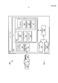
Обратимся теперь к чертежам, на которых одинаковые ссылочные позиции представляют одни и те же или аналогичные элементы, и обратимся сначала к фиг. 1, на которой система 100 для ручного управления эндоскопом с помощью инструментов наведения иллюстративно изображена в соответствии с одним из вариантов осуществления. Система 100 может содержать рабочую станцию или консоль 108, с которой процедуры (например, эндоскопия) контролируются и управляются. Рабочая станция 108 предпочтительно содержит один или более процессоров 138 и память 110 для хранения программ и приложений. Следует понимать, что функции и узлы системы 100 могут интегрироваться в одну или более рабочих станций или систем.We now turn to the drawings, in which the same reference numbers represent the same or similar elements, and first turn to FIG. 1, in which a
В памяти 110 могут храниться изображения 112. Изображения 112 могут включать изображения, полученные до операции и изображения, полученные во время операции, которые могут быть получены от систем, включающих, но не ограничивающихся указанным, систему магнитно-резонансной визуализации (MRI), систему компьютерной томографии (CT), рентгеновскую систему, 3D ультразвуковую систему и т.д. В памяти 110 также могут храниться изображения 114 прибора для наблюдения, полученные от прибора 102 для наблюдения. В предпочтительном варианте осуществления прибор 102 для наблюдения представляет собой эндоскоп для получения изображения до операции из места оперативного вмешательства с камеры 106. Изображения 114 прибора для наблюдения могут, предпочтительно, содержать видео с камеры 106 эндоскопа 102.
Настоящие принципы могут быть применены для различных приложений направляемой посредством эндоскопа минимально инвазивной хирургии. Например, настоящие принципы могут применяться для кардиальной хирургии (например, минимально инвазивное обходное шунтирование коронарной артерии, закрытие дефекта межпредсердной перегородки, пластика/протезирование клапана и т.д.), лапароскопической хирургии (например, гистерэктомии, простатэктомии, операции на желчном пузыре и т.д.), хирургии через естественные отверстия, легочной/бронхоскопической хирургии, нейрохирургических вмешательств и видеоассистированной торакальной хирургии. Однако следует отметить, что идеи настоящих принципов являются намного более широкими, чем указано выше, поскольку прибор 102 для наблюдения может включать любой тип прибора для наблюдения для приложений различных типов. В одном типовом варианте осуществления настоящие принципы могут быть применены для ручного наведения гибкого бура при перемещении в трубопроводе. Также предполагаются и другие применения.These principles can be applied to various applications of minimally invasive surgery guided by an endoscope. For example, these guidelines can be applied to cardiac surgery (e.g. minimally invasive coronary artery bypass grafting, atrial septal defect closure, plastic / valve prosthetics, etc.), laparoscopic surgery (e.g. hysterectomy, prostatectomy, gall bladder surgery, etc. etc.), surgery through natural openings, pulmonary / bronchoscopic surgery, neurosurgical interventions, and video-assisted thoracic surgery. However, it should be noted that the ideas of these principles are much broader than those indicated above, since the
Рабочая станция 108 может содержать один или более дисплеев 134 для просмотра изображений 112, полученных до операции и во время операции, и изображений 114 прибора для наблюдения, включая функции наведения по настоящим принципам. Дисплей 134 может также позволять пользователю взаимодействовать с рабочей станцией 108 и ее компонентами и функциями. Этому дополнительно способствует пользовательский интерфейс 136, который может содержать клавиатуру, "мышь", джойстик, или любое другое периферийное устройство или элемент управления для обеспечения возможности взаимодействия пользователя с рабочей станцией 108.
Исполняемая компьютером программа 116 хранится в памяти 110 рабочей станции 108. Программа 116 может содержать ряд модулей, каждый из которых выполнен с возможностью выполнения различных функций. Следует понимать, что модули могут быть реализованы в различных комбинациях аппаратного и программного обеспечения.The
Программа 116 может содержать регистрирующий модуль 118, который выполнен с возможностью выполнения регистрации между изображениями 112 (например, изображениями, полученными до операции и/или изображениями, полученными во время операции), и изображениями 114 прибора для наблюдения (например, эндоскопа). Регистрация выполняется в соответствии с известным в технике.The
Программа 116 может также содержать модуль 120 выбора, который выполнен с возможностью обеспечения пользователю (например, хирургу) возможности выбора представляющих интерес областей на изображениях 112, полученных до операции или во время операции (например, CT или рентгеновских). Например, выбранная представляющая интерес область может быть целевой обходной артерией в процедуре обходного шунтирования коронарной артерии. Модуль 120 выбора может включать использование дисплея 134 и пользовательского интерфейса 136 для способствования данному выбору. Модуль 120 выбора затем преобразует выбранную систему координат представляющих интерес областей изображения, полученного до операции и/или во время операции, к системе координат эндоскопа с применением регистрационного преобразования, определенного в регистрационном модуле 118.
Программа 116 может содержать модуль 122 наведения, который выполнен с возможностью использования выбранных представляющих интерес областей в виде с эндоскопа с целью определения множества указателей наведения. Модуль 122 наведения может содержать, но не ограничивается указанным, модуль 124 направления, модуль 126 траектории или модуль 128 расстояния, или все указанные модули. Другие указатели также были предусмотрены.
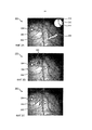
Модуль 124 направления определяет направление от текущего центра изображения с эндоскопа к выбранным представляющим интерес областям для того, чтобы наложить указатель управления на изображение с эндоскопа. Обратимся ненадолго к фиг. 2A; на ней иллюстративно показано изображение с эндоскопа, содержащее наложенные указатели 200, в соответствии с одним из вариантов осуществления. Указатель 206 направления накладывается на изображение с эндоскопа, чтобы показать направление от центра изображения 202 эндоскопа к выбранным представляющим интерес областям 204.The direction module 124 determines the direction from the current center of the image from the endoscope to the selected areas of interest in order to overlay the control pointer on the image from the endoscope. Turning briefly to FIG. 2A; it illustratively shows an image from an endoscope containing superposed
Модуль 122 наведения с фиг. 1 может содержать модуль 126 траектории для дополнительной помощи пользователю (например, хирургу или ассистенту) в проведении эндоскопа. Обратимся ненадолго к фиг. 2A; след 208 эндоскопа накладывается на изображение с эндоскопа, чтобы показать движение эндоскопа. След 208 генерируется посредством отслеживания положения одной или более анатомических особенностей, которые располагаются в центре изображения с эндоскопа, и наложения стрелки, чтобы отметить данное положение на изображении эндоскопа. В каждом кадре или периоде кадров текущая особенность в центре изображения накладывается со стрелкой на изображении эндоскопа, при этом продолжается отслеживание особенностей, ранее находившихся в центре изображения. Посредством продолжения данного процесса может быть создан визуальный след, чтобы помочь пользователю, регулирующему эндоскоп, в передвижении к выбранным представляющим интерес областям 204.
Направление следа 208 может сравниваться с представляющей интерес целевой областью 204 для отображения угловой погрешности с использованием визуальных подсказок. В одном из вариантов осуществления циферблат 210 может быть изображен с использованием стрелок 212 и 214, чтобы указать угловое смещение между движением 208 эндоскопа и направлением к выбранным представляющим интерес областям 206, соответственно. Другие визуальные подсказки, обозначающие угловую погрешность, также предусматриваются. Например, может быть отображен угол (например, в градусах) между направлением к выбранным представляющим интерес областям 206 и движением эндоскопа 102.The direction of the
Модуль 122 наведения может также содержать модуль 128 расстояния, который выполнен с возможностью указания расстояния от центра изображения с эндоскопа до представляющих интерес целевых областей. Обратимся ненадолго к фиг. 2B; изображение с эндоскопа с наложенным указателем 220 погрешности расстояния иллюстративно изображено в соответствии с одним из вариантов осуществления. Изображение с эндоскопа может содержать указатель 206 направления, показывающий направление от центра изображения 202 с эндоскопа до представляющей интерес целевой области 204. В одном из вариантов осуществления расстояние 222 (например, в пикселях) может быть показано как число на экране. В другом варианте осуществления линия между центром изображения 202 с эндоскопа и выбранными представляющими интерес областями 204 может быть представлена как функция расстояния. Например, как показано на фиг. 2C, изображение с эндоскопа с наложенным указателем расстояния, использующим виртуальную пружину 240, иллюстративно изображается в соответствии с одним из вариантов осуществления. Виртуальная пружина 242 соединяет центр изображения 202 с эндоскопа с выбранными представляющими интерес областями 204. Виртуальная пружина может становиться растянутой, если расстояние между двумя точками возрастает, и сжатой, если расстояние становится меньше. Также предусматриваются другие указатели погрешности расстояния. Например, цвет линии между центром изображения 202 с эндоскопа и выбранными представляющими интерес областями 204 может изменяться с расстоянием, при этом на экране отображаются условные обозначения, определяющие цвета. В другом варианте осуществления может быть изменена толщина линии при изменении расстояния.The
В еще одном варианте осуществления настоящих принципов модуль 124 направления с фиг. 1 может накладывать контрольные анатомические направления на изображение с эндоскопа. При регистрации изображений 112, полученных до операции и во время операции, на изображениях 114 с эндоскопа регистрационным модулем 118, определяются контрольные анатомические направления изображений, полученных до операции и во время операции. Контрольные анатомические направления преобразуются в систему координат эндоскопа и накладываются на изображение с эндоскопа. Контрольные анатомические направления могут включать, но не ограничиваются указанным, направления вперед/назад, влево/право и к голове/к ногам. Также предусмотрены другие анатомические направления.In yet another embodiment of the present principles, the direction module 124 of FIG. 1 may superimpose control anatomical directions on the image from the endoscope. When registering
С использованием наложенных указателей наведения модуля 122 наведения, пользователь управляет эндоскопом 102. Движение эндоскопа отслеживается, как обсуждалось выше, с целью определения того, достиг ли эндоскоп 102 выбранных представляющих интерес областей. Операции модуля 122 наведения повторяются, пока не будут достигнуты выбранные представляющие интерес области. Как только выбранная представляющая интерес область достигается, процесс завершается.Using superimposed guidance indicators of the
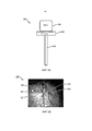
В одном из вариантов осуществления настоящих принципов программа 116 с фиг. 1 может также содержать модуль 130 привода для дополнительного способствования передвижению эндоскопа 102 пользователем. Модуль 130 запуска выполнен с возможностью предварительного ориентирования камеры 106 с применением имеющей привод платформы 104 таким образом, чтобы система координат камеры соответствовала предпочтительной системе координат пользователя. Модуль 130 привода получает направление, которому пользователь предпочитает соответствовать, например, направление "вверх". Например, пользователь может физически переместить эндоскоп в предпочтительное направление "вверх". Угол между физическим движением эндоскопа и реальным направлением вверх на изображении с эндоскопа вычисляется и передается в качестве входного значения на имеющую привод платформу, которая предварительно ориентирует камеру соответствующим образом. Следует отметить, что соответствующее направление не ограничено направлением "вверх", а может включать любое направление.In one embodiment of the present principles,
Обратимся теперь к фиг. 3A; система 300 для ориентации системы координат камеры эндоскопа в соответствии с системой координат пользователя эндоскопа иллюстративно изображена в соответствии с одним из вариантов осуществления. Камера 106 устанавливается на имеющей привод платформе 104 на приборе 102 для наблюдения. Имеющая привод платформа 104 вращается в соответствии с полученным углом, чтобы соответствующим образом ориентировать камеру. Обратимся ненадолго к фиг. 3B, на которой показан иллюстративный пример изображения с эндоскопа с наложенными ориентирующими указателями 320 в соответствии с одним из вариантов осуществления. Пользователь перемещает эндоскоп в предпочтительное направление "вверх", что приводит к передвижению эндоскопа 324 из центра указателя 202 изображения. Угол между движением эндоскопа 324 и реальным направлением "вверх" изображения 322 вычисляется для определения угла 326, который передается приводимую в движение платформу 104, чтобы соответствующим образом ориентировать камеру.Turning now to FIG. 3A; a
Обратимся теперь к фиг. 4; способ 400 для ручного управления эндоскопом с помощью инструментов наведения иллюстративно изображен в соответствии с одним из вариантов осуществления. В блоке 402 изображения с прибора для наблюдения регистрируются на изображениях, полученных до операции и/или во время операции. Изображения прибора для наблюдения предпочтительно представляют собой изображения с эндоскопа, имеющего камеру для получения изображения места проведения операции во время операции. Изображения с эндоскопа могут, предпочтительно, содержать видео. Изображения, полученные до операции и/или во время операции могут быть получены от систем, включающих, но не ограничивающихся указанным, систему MRI, систему CT, рентгеновскую систему, 3D ультразвуковую систему и т.д. Регистрация выполняется в соответствии со способами известными в технике.Turning now to FIG. four; A
В блоке 404 представляющие интерес области могут быть выбраны на изображениях, полученных до операции и во время операции. В блоке 406 выбранные представляющие интерес области могут быть преобразованы из системы координат изображений, полученных до операции и во время операции, к системе координат изображений с эндоскопа. Это может включать использование регистрационного преобразования, определенного в блоке 402.At a
В блоке 408 направление от текущего центра изображения с эндоскопа к выбранным представляющим интерес областям определяется на изображении с эндоскопа. С использованием этого направления в блоке 410 указатели наведения накладываются на изображение с эндоскопа. Указатели наведения могут включать, например, но не ограничиваясь указанным, указатель направления, трассировщик эндоскопа, указатель погрешности направления, указатель погрешности расстояния и указатель контрольного анатомического направления. Также предусматриваются другие указатели наведения.At
В одном из вариантов осуществления указатели наведения могут включать указатель направления, наложенный на изображение с эндоскопа, чтобы показать направление от текущего центра изображения с эндоскопа к выбранным представляющим интерес областям. В другом варианте осуществления след эндоскопа может быть наложен на изображение с эндоскопа, показывая движение эндоскопа. След может генерироваться посредством отслеживания положения каждой анатомической особенности, которая располагается в центре изображения с эндоскопа, и наложения стрелки для обозначения этого местоположения на изображении с эндоскопа. В каждом кадре или периоде кадров текущая особенность в центре изображения накладывается со стрелкой на изображение эндоскопа, при этом продолжается отслеживание особенностей, ранее находившихся в центре изображения. При продолжении этого процесса положения каждой из особенностей отображаются на изображении с эндоскопа, чтобы предоставить визуальный след, который может помочь пользователю передвигать эндоскоп.In one embodiment, the guidance indicators may include a direction indicator superimposed on the image from the endoscope to show the direction from the current center of the image from the endoscope to the selected areas of interest. In another embodiment, the endoscope trace may be superimposed on the image from the endoscope, showing the movement of the endoscope. A trace can be generated by tracking the position of each anatomical feature, which is located in the center of the image from the endoscope, and overlapping the arrows to indicate this location in the image from the endoscope. In each frame or frame period, the current feature in the center of the image is superimposed with an arrow on the image of the endoscope, while continuing to monitor features previously located in the center of the image. As this process continues, the positions of each feature are displayed on the image from the endoscope to provide a visual trace that can help the user move the endoscope.
В еще одном варианте осуществления след эндоскопа может сравниваться с направлением к выбранным представляющим интерес областям с целью определения угловой погрешности, представляющей смещение угла между движением эндоскопа и направлением к выбранным представляющим интерес областям. Угловая погрешность может быть наложена на изображение с эндоскопа с использованием визуальных подсказок. В одном из вариантов осуществления циферблат, содержащий две стрелки, накладывается на изображение с эндоскопа, при этом каждая стрелка показывает след эндоскопа и направление к выбранным представляющим интерес областям, соответственно. В другом примере угловая погрешность может быть указана посредством отображения угла (например, в градусах) на изображении с эндоскопа.In yet another embodiment, the trace of the endoscope can be compared with the direction to the selected areas of interest in order to determine the angular error representing the angle offset between the movement of the endoscope and the direction to the selected areas of interest. Angular error can be superimposed on the image from the endoscope using visual cues. In one embodiment, a dial containing two hands is superimposed on an image from an endoscope, with each hand showing an endoscope trace and direction to selected areas of interest, respectively. In another example, the angular error can be indicated by displaying the angle (for example, in degrees) in the image from the endoscope.
В одном из вариантов осуществления указатели наведения могут содержать указатель погрешности расстояния, наложенный на изображение с эндоскопа. При перемещении эндоскопа расстояние от центра изображения с эндоскопа до выбранных представляющих интерес областей изменяется. Погрешность расстояния может быть наложена на изображения с эндоскопа, чтобы помочь пользователю перемещать эндоскоп. Например, расстояние (например, в пикселях) может быть показано как число на экране. В другом примере линия, которая соединяет центр изображения с эндоскопа и выбранные представляющие интерес области, может быть представлена как функция расстояния. Это может включать представление линии в виде виртуальной пружины, которая может становиться растянутой, если расстояние возрастает, и сжатой, если расстояние становится меньше. Альтернативно, цвет или толщина линии могут изменяться в соответствии с расстоянием. Также предусматриваются другие представления погрешности расстояния.In one embodiment, the guidance indicators may comprise a distance error indicator superimposed on the image from the endoscope. As the endoscope moves, the distance from the center of the image from the endoscope to the selected areas of interest changes. Distance accuracy can be superimposed on images from the endoscope to help the user move the endoscope. For example, the distance (for example, in pixels) can be shown as a number on the screen. In another example, a line that connects the center of the image from the endoscope and selected areas of interest can be represented as a function of distance. This may include representing the line as a virtual spring, which can become stretched if the distance increases, and compressed if the distance becomes less. Alternatively, the color or thickness of the line may vary according to the distance. Other representations of distance error are also provided.
В другом варианте осуществления контрольные анатомические направления могут быть наложены на изображения с эндоскопа. При регистрации изображений, полученных до операции и во время операции (блок 402), контрольные анатомические направления изображений, полученных до операции и во время операции, определяются и преобразуются в вид с эндоскопа. Контрольные анатомические направления могут включать, например, направления вперед/назад, влево/право и к голове/к ногам. Также предусматриваются другие контрольные анатомические направления.In another embodiment, control anatomical directions can be superimposed on images from an endoscope. When registering images obtained before the operation and during the operation (block 402), the control anatomical directions of the images obtained before the operation and during the operation are determined and converted into a view from the endoscope. Control anatomical directions may include, for example, forward / backward directions, left / right, and toward the head / legs. Other control anatomical directions are also provided.
В блоке 414, используя указатели наведения, наложенные на изображение с эндоскопа, пользователь может перемещать эндоскоп с повышенной эффективностью. Движение эндоскопа отслеживается с целью определения, достигается ли представляющая интерес выбранная область. В блоке 416, если выбранная представляющая интерес область не достигнута, повторяются шаги 408, 410, 414 и 416, пока выбранная представляющая интерес область не будет достигнута в блоке 418. Предпочтительно, настоящие принципы помогают пользователю перемещать эндоскоп эффективно, что приводит к сокращению времени операции.At
В одном из вариантов осуществления настоящего изобретения, в блоке 412, камера эндоскопа может быть предварительно ориентирована таким образом, чтобы система координат камеры соответствовала предпочтительной системе координат пользователя. Пользователь может указать предпочтительное направление, например, "вверх". Это может включать физическое перемещение пользователем эндоскопа в предпочтительном направление "вверх". Угол между физическим движением эндоскопа и фактическим направлением "вверх" изображения с эндоскопа вычисляется и подается в качестве входных данных на имеющую привод платформу, установленную между камерой и эндоскопом. Имеющая привод платформа вращает камеру в соответствии с полученным углом, чтобы помочь пользователю в перемещении эндоскопа. Следует отметить, что соответствующее направление не ограничено направлением "вверх", а может включать любое направление.In one embodiment of the present invention, at
При интерпретации прилагаемой формулы изобретения следует понимать что:In interpreting the appended claims, it should be understood that:
a) слово "содержащее" не исключает наличия других элементов или действий, отличных от включенных в данный пункт формулы изобретения;a) the word “comprising” does not exclude the presence of other elements or actions other than those included in this claim;
b) если элемент указан в единственном числе, это не исключают наличия множества таких элементов;b) if an element is indicated in the singular, this does not exclude the presence of a plurality of such elements;
c) любые условные обозначения в формуле изобретения не ограничивают его объем;c) any symbols in the claims do not limit its scope;
d) несколько "средств" могут быть представлены одним и тем же элементом, или аппаратным обеспечением, или программным обеспечением, реализующим структуру или функцию; иd) several “tools” may be represented by the same element, or hardware, or software that implements a structure or function; and
e) никакая конкретная последовательность действий не является обязательной, если это не указано явно.e) no specific sequence of actions is required unless explicitly stated.
После описания предпочтительных вариантов осуществления для инструментов наведения для ручного управления эндоскопом с использованием 3D-изображений, полученных до операции и во время операции (которые предполагаются иллюстративными и не ограничивающими), следует отметить, что изменения и вариации могут быть сделаны специалистами в данной области техники с учетом указанных выше идей. Поэтому следует понимать, что изменения могут быть произведены в конкретных вариантах осуществления, рассмотренных в данном раскрытии, которые находятся в пределах объема вариантов осуществления, раскрытых в настоящем описании, как изложено в прилагаемой формуле изобретения. Таким образом, после описания подробностей и особенностей, требуемых патентными законами, заявляемый объект, который предполагается защитить патентом на изобретение, формулируется в прилагаемой формуле изобретения.After describing preferred embodiments for guidance tools for manually controlling an endoscope using 3D images obtained before and during surgery (which are assumed to be illustrative and not restrictive), it should be noted that changes and variations can be made by those skilled in the art with considering the above ideas. Therefore, it should be understood that changes may be made in the specific embodiments discussed in this disclosure, which are within the scope of the embodiments disclosed herein, as set forth in the appended claims. Thus, after describing the details and features required by patent laws, the claimed object, which is supposed to be protected by a patent for an invention, is formulated in the attached claims.
Claims (38)
Applications Claiming Priority (3)
| Application Number | Priority Date | Filing Date | Title |
|---|---|---|---|
| US201261635327P | 2012-04-19 | 2012-04-19 | |
| US61/635,327 | 2012-04-19 | ||
| PCT/IB2013/052797 WO2013156893A1 (en) | 2012-04-19 | 2013-04-08 | Guidance tools to manually steer endoscope using pre-operative and intra-operative 3d images |
Publications (2)
| Publication Number | Publication Date |
|---|---|
| RU2014146310A RU2014146310A (en) | 2016-06-10 |
| RU2668490C2 true RU2668490C2 (en) | 2018-10-01 |
Family
ID=48539312
Family Applications (1)
| Application Number | Title | Priority Date | Filing Date |
|---|---|---|---|
| RU2014146310A RU2668490C2 (en) | 2012-04-19 | 2013-04-08 | Guidance tools to manually steer endoscope using pre-operative and intra-operative 3d images |
Country Status (6)
| Country | Link |
|---|---|
| US (1) | US11452464B2 (en) |
| EP (1) | EP2838412B1 (en) |
| JP (1) | JP6174676B2 (en) |
| CN (1) | CN104244800B (en) |
| RU (1) | RU2668490C2 (en) |
| WO (1) | WO2013156893A1 (en) |
Families Citing this family (42)
| Publication number | Priority date | Publication date | Assignee | Title |
|---|---|---|---|---|
| US9510771B1 (en) | 2011-10-28 | 2016-12-06 | Nuvasive, Inc. | Systems and methods for performing spine surgery |
| US9295372B2 (en) * | 2013-09-18 | 2016-03-29 | Cerner Innovation, Inc. | Marking and tracking an area of interest during endoscopy |
| US9848922B2 (en) | 2013-10-09 | 2017-12-26 | Nuvasive, Inc. | Systems and methods for performing spine surgery |
| CN105611884B (en) | 2013-10-09 | 2019-06-28 | 纽文思公司 | The system for being designed in art during vertebra program of performing the operation and evaluating spine malformation correction |
| US20150157197A1 (en) * | 2013-12-09 | 2015-06-11 | Omer Aslam Ilahi | Endoscopic image overlay |
| JP6725423B2 (en) * | 2014-02-11 | 2020-07-15 | コーニンクレッカ フィリップス エヌ ヴェKoninklijke Philips N.V. | System for visualizing anatomical targets |
| DE102014203097A1 (en) * | 2014-02-20 | 2015-08-20 | Siemens Aktiengesellschaft | A method of assisting navigation of an endoscopic device |
| CN106456252B (en) * | 2014-03-28 | 2020-05-08 | 直观外科手术操作公司 | Quantitative three-dimensional imaging of surgical scenes |
| KR102387096B1 (en) * | 2014-03-28 | 2022-04-15 | 인튜어티브 서지컬 오퍼레이션즈 인코포레이티드 | Quantitative three-dimensional visualization of instruments in a field of view |
| EP3157425A4 (en) | 2014-06-17 | 2017-11-15 | Nuvasive, Inc. | Systems and methods for planning, performing, and assessing spinal correction during surgery |
| JP6663571B2 (en) * | 2014-11-06 | 2020-03-13 | ソニー株式会社 | Endoscope image processing apparatus, method of operating endoscope image processing apparatus, and program |
| US10013808B2 (en) | 2015-02-03 | 2018-07-03 | Globus Medical, Inc. | Surgeon head-mounted display apparatuses |
| US20160262800A1 (en) | 2015-02-13 | 2016-09-15 | Nuvasive, Inc. | Systems and methods for planning, performing, and assessing spinal correction during surgery |
| US10406054B1 (en) | 2015-02-18 | 2019-09-10 | Nuvasive, Inc. | Systems and methods for facilitating surgical procedures |
| JP6577031B2 (en) * | 2015-07-08 | 2019-09-18 | オリンパス株式会社 | Endoscope device |
| CN108472090B (en) * | 2015-12-29 | 2021-06-18 | 皇家飞利浦有限公司 | System, control unit and method for controlling a surgical robot |
| WO2017122322A1 (en) * | 2016-01-14 | 2017-07-20 | オリンパス株式会社 | Medical manipulator system |
| AU2017210124B2 (en) | 2016-01-22 | 2021-05-20 | Nuvasive, Inc. | Systems and methods for facilitating spine surgery |
| ES2877761T3 (en) | 2016-03-02 | 2021-11-17 | Nuvasive Inc | Systems and Procedures for Spinal Correction Surgical Planning |
| JP7041068B6 (en) * | 2016-03-17 | 2022-05-30 | コーニンクレッカ フィリップス エヌ ヴェ | Control units, systems, and methods for controlling hybrid robots with proximal and flexible distal parts. |
| WO2018005861A1 (en) | 2016-06-30 | 2018-01-04 | Intuitive Surgical Operations, Inc. | Graphical user interface for displaying guidance information during an image-guided procedure |
| US11612384B2 (en) | 2016-06-30 | 2023-03-28 | Intuitive Surgical Operations, Inc. | Graphical user interface for displaying guidance information in a plurality of modes during an image-guided procedure |
| CN110621252B (en) * | 2017-04-18 | 2024-03-15 | 直观外科手术操作公司 | Graphical user interface for monitoring image-guided procedures |
| US20190254753A1 (en) | 2018-02-19 | 2019-08-22 | Globus Medical, Inc. | Augmented reality navigation systems for use with robotic surgical systems and methods of their use |
| JP6990292B2 (en) * | 2018-02-21 | 2022-01-12 | オリンパス株式会社 | Medical system and how to operate the medical system |
| US10667875B2 (en) * | 2018-06-27 | 2020-06-02 | Auris Health, Inc. | Systems and techniques for providing multiple perspectives during medical procedures |
| US20210290317A1 (en) * | 2018-07-31 | 2021-09-23 | Intuitive Surgical Operations, Inc. | Systems and methods for tracking a position of a robotically-manipulated surgical instrument |
| US11229492B2 (en) | 2018-10-04 | 2022-01-25 | Biosense Webster (Israel) Ltd. | Automatic probe reinsertion |
| CN110742690A (en) * | 2019-09-12 | 2020-02-04 | 东南大学苏州医疗器械研究院 | Method for configuring endoscope and terminal equipment |
| US11992373B2 (en) | 2019-12-10 | 2024-05-28 | Globus Medical, Inc | Augmented reality headset with varied opacity for navigated robotic surgery |
| US11464581B2 (en) | 2020-01-28 | 2022-10-11 | Globus Medical, Inc. | Pose measurement chaining for extended reality surgical navigation in visible and near infrared spectrums |
| US11382699B2 (en) | 2020-02-10 | 2022-07-12 | Globus Medical Inc. | Extended reality visualization of optical tool tracking volume for computer assisted navigation in surgery |
| US11207150B2 (en) | 2020-02-19 | 2021-12-28 | Globus Medical, Inc. | Displaying a virtual model of a planned instrument attachment to ensure correct selection of physical instrument attachment |
| US11607277B2 (en) | 2020-04-29 | 2023-03-21 | Globus Medical, Inc. | Registration of surgical tool with reference array tracked by cameras of an extended reality headset for assisted navigation during surgery |
| US11153555B1 (en) | 2020-05-08 | 2021-10-19 | Globus Medical Inc. | Extended reality headset camera system for computer assisted navigation in surgery |
| US11510750B2 (en) | 2020-05-08 | 2022-11-29 | Globus Medical, Inc. | Leveraging two-dimensional digital imaging and communication in medicine imagery in three-dimensional extended reality applications |
| US11382700B2 (en) | 2020-05-08 | 2022-07-12 | Globus Medical Inc. | Extended reality headset tool tracking and control |
| WO2022044606A1 (en) * | 2020-08-24 | 2022-03-03 | 富士フイルム株式会社 | Medical image processing apparatus, medical image processing method, endoscope system, and medical image processing program |
| US11737831B2 (en) | 2020-09-02 | 2023-08-29 | Globus Medical Inc. | Surgical object tracking template generation for computer assisted navigation during surgical procedure |
| US20220202500A1 (en) * | 2020-12-30 | 2022-06-30 | Canon U.S.A., Inc. | Intraluminal navigation using ghost instrument information |
| CN116829089A (en) * | 2020-12-30 | 2023-09-29 | 直观外科手术操作公司 | System for updating a graphical user interface based on intra-operative imaging |
| US20230053189A1 (en) * | 2021-08-11 | 2023-02-16 | Terumo Cardiovascular Systems Corporation | Augmented-reality endoscopic vessel harvesting |
Citations (5)
| Publication number | Priority date | Publication date | Assignee | Title |
|---|---|---|---|---|
| US20020077544A1 (en) * | 2000-09-23 | 2002-06-20 | Ramin Shahidi | Endoscopic targeting method and system |
| RU2288636C2 (en) * | 2000-03-28 | 2006-12-10 | Форт Фотоникс Лимитед | Method and systems for detecting parameters and mapping of tissue lesions |
| US20080262297A1 (en) * | 2004-04-26 | 2008-10-23 | Super Dimension Ltd. | System and Method for Image-Based Alignment of an Endoscope |
| US20080287783A1 (en) * | 2007-05-16 | 2008-11-20 | General Electric Company | System and method of tracking delivery of an imaging probe |
| WO2010111090A1 (en) * | 2009-03-26 | 2010-09-30 | Intuitive Surgical Operations, Inc. | System for providing visual guidance for steering a tip of an endoscopic device towards one or more landmarks and assisting an operator in endoscopic navigation |
Family Cites Families (7)
| Publication number | Priority date | Publication date | Assignee | Title |
|---|---|---|---|---|
| DE69726576T2 (en) * | 1996-02-15 | 2004-10-14 | Biosense, Inc., Miami | Placemark sample |
| US7343195B2 (en) * | 1999-05-18 | 2008-03-11 | Mediguide Ltd. | Method and apparatus for real time quantitative three-dimensional image reconstruction of a moving organ and intra-body navigation |
| US20060036162A1 (en) | 2004-02-02 | 2006-02-16 | Ramin Shahidi | Method and apparatus for guiding a medical instrument to a subsurface target site in a patient |
| US7720521B2 (en) * | 2004-04-21 | 2010-05-18 | Acclarent, Inc. | Methods and devices for performing procedures within the ear, nose, throat and paranasal sinuses |
| WO2007129493A1 (en) * | 2006-05-02 | 2007-11-15 | National University Corporation Nagoya University | Medical image observation support device |
| CN101826780B (en) * | 2009-03-07 | 2013-08-21 | 深圳先进技术研究院 | System for driving capsule endoscope |
| CN102405010B (en) * | 2009-04-20 | 2014-07-16 | 奥林巴斯医疗株式会社 | Subject internal examination system |
-
2013
- 2013-04-08 EP EP13726277.0A patent/EP2838412B1/en active Active
- 2013-04-08 US US14/394,611 patent/US11452464B2/en active Active
- 2013-04-08 RU RU2014146310A patent/RU2668490C2/en active
- 2013-04-08 CN CN201380020657.8A patent/CN104244800B/en active Active
- 2013-04-08 WO PCT/IB2013/052797 patent/WO2013156893A1/en active Application Filing
- 2013-04-08 JP JP2015506331A patent/JP6174676B2/en active Active
Patent Citations (5)
| Publication number | Priority date | Publication date | Assignee | Title |
|---|---|---|---|---|
| RU2288636C2 (en) * | 2000-03-28 | 2006-12-10 | Форт Фотоникс Лимитед | Method and systems for detecting parameters and mapping of tissue lesions |
| US20020077544A1 (en) * | 2000-09-23 | 2002-06-20 | Ramin Shahidi | Endoscopic targeting method and system |
| US20080262297A1 (en) * | 2004-04-26 | 2008-10-23 | Super Dimension Ltd. | System and Method for Image-Based Alignment of an Endoscope |
| US20080287783A1 (en) * | 2007-05-16 | 2008-11-20 | General Electric Company | System and method of tracking delivery of an imaging probe |
| WO2010111090A1 (en) * | 2009-03-26 | 2010-09-30 | Intuitive Surgical Operations, Inc. | System for providing visual guidance for steering a tip of an endoscopic device towards one or more landmarks and assisting an operator in endoscopic navigation |
Also Published As
| Publication number | Publication date |
|---|---|
| US11452464B2 (en) | 2022-09-27 |
| CN104244800A (en) | 2014-12-24 |
| RU2014146310A (en) | 2016-06-10 |
| JP2015514492A (en) | 2015-05-21 |
| EP2838412A1 (en) | 2015-02-25 |
| WO2013156893A1 (en) | 2013-10-24 |
| CN104244800B (en) | 2017-05-17 |
| JP6174676B2 (en) | 2017-08-02 |
| US20150073265A1 (en) | 2015-03-12 |
| EP2838412B1 (en) | 2020-09-09 |
Similar Documents
| Publication | Publication Date | Title |
|---|---|---|
| RU2668490C2 (en) | Guidance tools to manually steer endoscope using pre-operative and intra-operative 3d images | |
| US11980505B2 (en) | Visualization of depth and position of blood vessels and robot guided visualization of blood vessel cross section | |
| US9782198B2 (en) | Localization of robotic remote center of motion point using custom trocar | |
| EP2866638B1 (en) | Enhanced visualization of blood vessels using a robotically steered endoscope | |
| US10772684B2 (en) | Spatial visualization of internal mammary artery during minimally invasive bypass surgery | |
| US10687911B2 (en) | Positioning and orientation of surgical tools during patient specific port placement | |
| US10799146B2 (en) | Interactive systems and methods for real-time laparoscopic navigation | |
| CN108969099B (en) | Correction method, surgical navigation system, electronic device and storage medium | |
| CN107847111B (en) | Endoscopic guidance of interactive planar slices from volumetric images | |
| WO2013186738A2 (en) | Guided incision planning for endoscopic minimally invasive surgery | |
| US20200359994A1 (en) | System and method for guiding ultrasound probe | |
| Suzuki et al. | Development of AR surgical navigation systems for multiple surgical regions | |
| Rassweiler et al. | Augmented reality for percutaneous renal interventions | |
| Langø et al. | Navigated ultrasound in laparoscopic surgery | |
| Yoshida et al. | Navigation in endourology, ureteroscopy | |
| Stallkamp et al. | Whole'O'Hand–A holistic intervention and interaction system: A novel concept for closed-loop liver surgery |