EP2838136B1 - Ion dosing device for an energy storage device, method for producing an ion dosing device and energy storage device - Google Patents
Ion dosing device for an energy storage device, method for producing an ion dosing device and energy storage device Download PDFInfo
- Publication number
- EP2838136B1 EP2838136B1 EP14002682.4A EP14002682A EP2838136B1 EP 2838136 B1 EP2838136 B1 EP 2838136B1 EP 14002682 A EP14002682 A EP 14002682A EP 2838136 B1 EP2838136 B1 EP 2838136B1
- Authority
- EP
- European Patent Office
- Prior art keywords
- energy
- ion
- separator
- ions
- guiding device
- Prior art date
- Legal status (The legal status is an assumption and is not a legal conclusion. Google has not performed a legal analysis and makes no representation as to the accuracy of the status listed.)
- Not-in-force
Links
Images

Classifications
-
- G—PHYSICS
- G21—NUCLEAR PHYSICS; NUCLEAR ENGINEERING
- G21K—HANDLING OF PARTICLES OR IONISING RADIATION NOT OTHERWISE PROVIDED FOR; IRRADIATION DEVICES; GAMMA RAY OR X-RAY MICROSCOPES
- G21K1/00—Arrangements for handling particles or ionising radiation, e.g. focusing or moderating
- G21K1/08—Deviation, concentration or focusing of the beam by electric or magnetic means
-
- H—ELECTRICITY
- H01—ELECTRIC ELEMENTS
- H01M—PROCESSES OR MEANS, e.g. BATTERIES, FOR THE DIRECT CONVERSION OF CHEMICAL ENERGY INTO ELECTRICAL ENERGY
- H01M50/00—Constructional details or processes of manufacture of the non-active parts of electrochemical cells other than fuel cells, e.g. hybrid cells
- H01M50/40—Separators; Membranes; Diaphragms; Spacing elements inside cells
- H01M50/409—Separators, membranes or diaphragms characterised by the material
- H01M50/411—Organic material
-
- H—ELECTRICITY
- H01—ELECTRIC ELEMENTS
- H01M—PROCESSES OR MEANS, e.g. BATTERIES, FOR THE DIRECT CONVERSION OF CHEMICAL ENERGY INTO ELECTRICAL ENERGY
- H01M50/00—Constructional details or processes of manufacture of the non-active parts of electrochemical cells other than fuel cells, e.g. hybrid cells
- H01M50/40—Separators; Membranes; Diaphragms; Spacing elements inside cells
- H01M50/489—Separators, membranes, diaphragms or spacing elements inside the cells, characterised by their physical properties, e.g. swelling degree, hydrophilicity or shut down properties
- H01M50/497—Ionic conductivity
-
- H—ELECTRICITY
- H01—ELECTRIC ELEMENTS
- H01M—PROCESSES OR MEANS, e.g. BATTERIES, FOR THE DIRECT CONVERSION OF CHEMICAL ENERGY INTO ELECTRICAL ENERGY
- H01M6/00—Primary cells; Manufacture thereof
- H01M6/30—Deferred-action cells
- H01M6/36—Deferred-action cells containing electrolyte and made operational by physical means, e.g. thermal cells
-
- H—ELECTRICITY
- H01—ELECTRIC ELEMENTS
- H01M—PROCESSES OR MEANS, e.g. BATTERIES, FOR THE DIRECT CONVERSION OF CHEMICAL ENERGY INTO ELECTRICAL ENERGY
- H01M2200/00—Safety devices for primary or secondary batteries
Definitions
- the present invention relates to the technical field of energy storage devices. More particularly, the present invention relates to an ion metering device for an energy storage device, a method of manufacturing an ion metering device for an energy storage device, and an energy storage device.
- Batteries or accumulators have a self-discharge, which means that such a battery is limited storable. For example, in today's commercially available cells, self-discharge may be at 1% of cell capacity per month. Because of this high self-discharge such batteries can not or only partially be used in cases where the batteries must be stored for a long period of time before use without the batteries being conditioned during storage. Thus, the high self-discharge makes storage of ten years or more difficult.
- EP 0 291 459 A2 describes a method for abrasive machining of optical bodies of crosslinked polymers.
- the publication US 2012/0237816 A1 relates to a bipolar battery having a substrate comprising a matrix of a thermoset polymer.
- the publication GB 23,265 AD 1911 relates to an aluminum grid for the electrodes of an electrical accumulator.
- the publication US 2005/0201715 A1 relates to a system for a magneto-optical device display.
- the publication US 6,326,105 B1 relates to a polymer electrolyte composite for electrochemical alkali metal devices obtained by coating an inert, lightweight, electrically insulating, non-woven glass fiber network containing a polyvinyl alcohol binder with a liquid polymer which may be ionically conductive and curing the polymer is formed to form a solid or semi-solid electrolyte composite.
- an ion metering device for a battery a method of manufacturing an ion metering device for an energy storage device, and an energy storage device.
- An energy storage device can not only be used to store energy. After activating the energy storage device, the energy storage device releases the stored energy in it and can be used as an energy delivery device or as a generator, for example to operate a circuit. The activation may place components of the energy storage device, such as an ion meter or the separator contained in the ion meter, in an electrically conductive state and / or in an ionically conductive state.
- an ion metering device for a battery has a first energy-conducting device with a first energy supply device and a separating device. Via the first energy supply device, the first energy-conducting device can be supplied with a first energy for the ion-metering device.
- the separating device is set up, in a first state of the ion metering device in which no energy is supplied via the first energy supply device, to block ions which would be transported past the first energy-conducting device.
- the ion metering device includes the energy directing device and a separator or barrier device, such as a barrier layer, which essentially allows charge carrier transport only when the separator has been destroyed or its ionic conductivity has been adjusted.
- the first energy-conducting device is set up to predefine the transport direction of the first energy in order to lead the first energy to a substantially specifiable position of the separating device within the ion-metering device and at this position to deliver the first energy within the ion-metering device to the separating device.
- the energy director emits the energy over the entire length of the energy director.
- the energy output can be achieved by means of a decoupling device at a specific position, for example by structuring gradients of a gradient optical fiber.
- the amount of the outputted first energy exceeds the number of times the separator is applied to the first energy directing means (102a, 103a, 104a, 105a, 106a) transported ions and / or the number of transmitted by the separator ions.
- the amount of emitted first energy determines the ion current flux density through the separator, in particular the ion current density, past or around the first energy director.
- the energy supplied from an energy source determines the amount of energy delivered, and thus the number of ions transported or transmitted.
- the separator may be selected to suit the type of energy used so that the energy released by the energy director interacts with the separator, interacts or is absorbed by the separator. The interaction or absorption of the energy can lead to an effect in the separator, which leads to a change in the transportability of ions.
- the choice of the separating device in particular the choice of the material of the separating device, can thus depend on the type of energy used for the first energy. In this case, the separating device or the barrier layer is selected such that substantially all the energy provided via the energy-conducting device can be absorbed.
- a photochemically decomposable polymer is used as the separating device within the ion metering device.
- the photochemically decomposable polymer is tuned to a particular wavelength of the laser radiation so that maximum decomposition occurs at a defined wavelength.
- the energy can be dissipated over the entire length of the energy control device.
- special measures such as the provision of a sheath, the energy output can be prevented at certain positions where no energy release is desired.
- the energy output can be promoted by appropriate modifications of the energy directing device, such as the provision of structuring.
- structures are introduced into a gradient optical fiber, which cause a partial decoupling of the radiation at defined positions. By such a modification, the position can be determined, at which the first energy is delivered to the separator.
- the separator may be configured to control a number of ions that are transported and / or blocked around the first energy director via the supplied energy.
- ions are transported past the energy directing device, in particular that the ions are transported through gaps formed by the energy directing device or by a plurality of energy directing devices.
- a method of manufacturing an ion metering device for an energy storage device has the provision of a first energy-conducting device and a first energy supply device, wherein the first energy supply device can be arranged on the first energy-conducting device.
- a first energy can be supplied to the first energy-conducting device via the first energy supply device.
- the first energy supply device can enable the coupling of a first energy into the first energy-conducting device, for example the coupling from an energy source.
- the provided first energy-conducting device is surrounded by a separating device, by means of which an ion transport can be prevented, or the first energy-conducting device is embedded in the above-mentioned separating device.
- the energy supply device in combination with the energy-conducting device and the separating device form the ion-metering device.
- the power-conducting device is laid in a plane such that, due to the shape of the routing, openings are formed between the energy-conducting device. These openings may be, for example, of a plurality of first power-conducting devices by arranging at least two power-conducting devices in parallel or in a grid, and / or by laying a single first one in a loop Energy control arise.
- the ion metering device or its separating device can be used as a separation medium or barrier layer for an ion transport device, for example for an electrolyte within a battery.
- the electrolyte may be used in conjunction with a separator. Because of its separating action, the ion metering device or its separating device can substantially block ion transport, in particular if the ion metering device and / or the separating device does not react with the ion transport device.
- a predeterminable number of ions can be guided around the energy-conducting device or led past the energy-conducting device within the ion-metering device.
- the number of ions transported within the ion metering device is determined by the amount of energy delivered to the separator by the energy directing means or the form of energy supplied.
- the ion-metering device may receive ions from an ion transport device or be part of the ion transport device.
- an ion channel may be used to guide the ions.
- the separating device Surrounding the first energy-conducting device within the ion-metering device with the separating device is such that the separating device is set up to block ions that would have been transported past the first energy-conducting device in a first state in which no energy is supplied via the first energy supply device For example, by blocking an ion transport device or by dosing the number of mobile ions in the separator.
- the first energy supply device is connected to the first energy-conducting device.
- the first energy-conducting device is set up to predefine the transport direction of the first energy in order to supply the first energy to a predeterminable position of the separating device to lead within the Ionendosiervorides and deliver the first energy to the separator at this position.
- the surrounding of the first energy-conducting device with the separating device takes place in such a way that, in a second state in which the first energy is supplied via the first energy supply device, the quantity of emitted first energy determines the number of ions transported past the separating device at the first energy-conducting device and / or determines the number of ions transmitted by the separator.
- the ion metering device can be switched between a blocked state and a conductive state.
- the first state may correspond to a rest state or storage state.
- the second state may correspond to an activated state.
- an energy storage device such as a battery or a rechargeable battery
- the energy storage device has a first electrode, a second electrode and an ion transport device and the ion metering device according to the invention.
- the ion metering device is in contact with the ion transport device to control a number of ions transported by the ion transport device.
- the number of ions transported can be controlled by the amount of energy supplied.
- switching between the first and second states switching of the ion metering device can be realized.
- the number of ions transported may essentially not matter, but only whether ions are transported and possibly whether the number of ions transported exceeds a predetermined threshold.
- the ion metering device is disposed between the first electrode and the second electrode.
- the first electrode may be an anode and the second electrode may be a cathode
- the ion transport device may be an electrolyte, also in conjunction with a separator.
- the energy storage device or the energy release device has at least three terminals, namely the first electrode, the second electrode and the energy supply device for activating and / or controlling the internal metering device or the separating device contained therein.
- the energy supplied to the ion metering device can act on the separation device essentially without conversion into another form of energy.
- the supplied light energy acts directly on the separation device.
- the conductivity of the material of the separator is influenced by the energy supply.
- the energy supply means can be considered as a control means for the ion current transported between the electrodes.
- the ion transistor in one example may operate substantially within a voltage source or energy storage device.
- the ionic conductivity of the material of the separator is selectively changed by means of light energy or by means of the energy of an electric field. Consequently, the energy storage device according to the invention may be referred to as an ion transistor.
- the separating device can be designed as a thin film or as a layer system.
- the property of the film or membrane can be influenced for ion switching and ion metering by means of an electric field.
- the Ionendosiervoriques can be used for dosing or switching of ion streams.
- the ionic conductivity of the film or membrane may be modulated and altered by influencing an ion channel by means of an electrostatic field.
- a field modulated polymeric ion channel may be useful which is formed by the combination of monomers, eg, alamethicin and gramicidin, and which can be assembled, deformed, or disrupted by an applied electrostatic field, thereby modulating ionic conductivity.
- a missile which has an energy storage device with the Ionendosiervorraum.
- a long shelf life is required especially in the military field of application.
- a long shelf life of batteries or accumulators is required, which are installed in military missiles.
- a long shelf life of batteries can be achieved with so-called thermal batteries, which are electrically inactive until their use, since the electrolyte, in particular the separator, becomes ionic conductive in the cell only upon activation of the battery, the cell or the accumulator the electrical functioning of the battery can be made.
- the ionic conductivity can be produced by the uncontrolled heating of the electrolyte, for example by means of a pyrotechnic propellant.
- thermal battery has only a short operating time in the order of a few minutes, since an electrolyte which is activated by pyrotechnic heating, limited in time remains conductive for ions.
- thermal batteries have, compared to other battery systems, e.g. to Li-ion cells (lithium-ion cells), a relatively low specific energy density.
- energy density is a parameter that plays a central role in a variety of applications. For example, the energy demand of individual consumers or the number of consumers in a variety of applications is steadily increasing.
- an energy storage device in which the ion metering device is used can be activated as required, even after a long time. It may be considered as one aspect of the present invention to control the ionic conductivity of a separator, barrier layer or separator, e.g. a separator membrane to control by means of supplied energy, to change, to control or to meter.
- the ionic conductivity can be controlled, for example, as a function of the amount of energy supplied or the supplied energy form, for example as a function of the radiation intensity, wavelength and irradiation time.
- the separator or barrier layer may be incorporated in a separator or separator membrane provided in an energy storage device to separate, for example, active materials.
- the separator may be applied as an additional barrier layer to the separator membrane of a battery or accumulator.
- the Ionendosiervoriques can be viewed with their separator as a switchable separator or as a controllable separator.
- a corresponding ion metering device with the associated separating device can also be referred to as a switchable separator for a battery or for a rechargeable battery.
- the ion metering device, the switchable separator, the additional barrier layer of the ion metering device or the additional separator membrane may comprise a network of energy-conducting devices, for example a network of optical fibers.
- Each of the energy control devices used can have a high power loss for the transport of the selected energy in the transport direction, so that a large part of the energy is discharged into an outer region of the energy-conducting device. Because of this high power dissipation, substantially a majority of the transported energy can be delivered from the energy directing device to the separator.
- the energy can be from an optical Radiation, a microwave, any other electromagnetic radiation form, an electric current, a magnetic field, an electric field, an electrostatic field, a magnetic field or as thermal radiation are transported.
- energy delivery from the energy director to the separator of the ion doser occurs through structures introduced into a gradient optical fiber which result in more coupling of a portion of the radiation at the position where the structures are located are arranged.
- the coupling out of the radiation takes place via losses in the reflection of the radiation in the interior of the optical waveguide.
- the extraction is via an electric field.
- the separating device or barrier layer can encase the energy-conducting device, so that the energy-conducting device is substantially completely surrounded by the separating device.
- the resulting in a loop-like installation or in a grid-like installation of the energy control device openings may thus be substantially closed with the separator.
- the combination of energy directing means and separating means may form an ion metering device which may be incorporated into an energy storage device. Any other three-dimensional shape besides the layer form is also conceivable.
- An example of a separator may be a photochemically decomposable polymer. This can react to the wavelength of a specific laser radiation and be decomposed.
- an optical fiber or an optical conductor can be used as an energy guiding device to guide the laser radiation through the separating device of the ion metering device.
- other forms of radiation are conceivable, such as visible light, UV (ultraviolet) radiation, and IR (infrared) radiation, which are guided with the corresponding conductors.
- the form of leadership can enhance the effect of the photochemical reaction increase.
- the Ionendosiervorraum is formed of an optical fiber and a photochemically decomposable polymer
- the optical fiber may be coated with the photochemically decomposable polymer or with a polymer whose chemical-physical properties can be set defined by means of specific radiation.
- the ionic conductivity of such a polymer may be referred to.
- a polymer whose chemical-physical property can be deliberately adjusted or metered by means of specific radiation or a photochemically decomposable polymer is an example of the separation device of an ion-metering device which interacts with a corresponding energy form which is guided in and out of the energy-directing device.
- the combination of the material used for the separation device and the energy source used and thus the used first energy control device and / or the second energy control device may be selected in the optical case so that the photon energy of the laser radiation used, for example, an eximer laser, greater than the binding energy of the covalent bonds in the polymer of the separator.
- the polymer used may be a hydroxy-substituted lower alkyl acrylate or methacrylate which is crosslinked with ethyl glycol dimethacrylate, ethylene glycol dimethacrylate or divinylbenzene.
- a crosslinked polymer having the following main covalent bonds can be used, e.g. Carbon-carbon, carbon-nitrogen, carbon-oxygen, silicon-carbon and / or silicon-oxygen.
- a crosslinked polymer is essentially a three-dimensional network.
- the polymers are especially selected so that neither the polymers used nor the resulting decomposition products with the ingredients or react the components of the energy storage device so that such a reaction and / or resulting reaction products are detrimental to the functionality of the energy storage, for example, affect the ion conductivity.
- the effectiveness of the radiation in decomposition may be heightenable when coherent radiation is used.
- the ion conductivity of the separator may be selectively adjusted by an electromagnetic field introduced by an energy supply device and an energy directing device. Due to the energy supply, the ion metering device can be used for switching or controlling ion currents. Foils or other thin layer systems can be used for the separating device. These allow an ion current when energized and are chemically resistant and / or inert to those substances that come into contact with the separator and that are a part of the energy storage device.
- an energy storage device can be protected against self-discharge and the time until the energy is to be supplied from the energy storage device can be increased. Consequently, the storage period or the provision period can be increased.
- the targeted control or the targeted metering of transported ions in the separating device it may also be possible to change an internal resistance of the energy storage device so that a controlled energy source can be realized. It is conceivable, for example, a control or regulation of the flowing electric currents in case of failure by dosing the ion current within the energy storage device.
- the ion metering device is arranged as a security device for a possible error case.
- the ion current in the cell is interrupted and the energy output of the energy storage device is prevented, for example by blocking the ion current.
- the blocking of the ion current can be done by switching off or switching on the electrical energy. It is possible to interconnect energy storage devices with the ion metering device in such a way that power-electronic tasks can be performed by at least one or a plurality of such energy storage devices with an ion metering device, e.g. a speed control of motors or a signal shaping.
- the ion metering device may be referred to as an electrochemical and / or electro-optical transistor. In this case, this transistor acts essentially within the energy source.
- the ion dosing device may be a controlled resistor for an ion current.
- the ion metering device is set up such that an ion current within the cell is possible only for the duration of the energy input by the energy-conducting device.
- the ion current is interrupted by the fact that the external energy supply is stopped.
- the additional introduction of the separator can increase the shelf life of essentially any battery or energy storage device that utilizes ion transport to release the stored energy
- a wide variety of battery types such as high-energy Li-ion batteries, can be modified to can be used in special long-term applications. This makes it possible to adapt different existing battery types so that they can be used in cases where a good shelf life and a quick operational readiness is required. For example, batteries with increased energy densities for missiles compared to thermal batteries can be used.
- the number of ions in the first state in which no power is supplied, the number of ions is transported and / or transmitted, and in the second state in which the first energy is supplied, the ion transport is blocked.
- a conductive state may be established without energy supply and a blocked state when energized.
- the number of ions transported is influenced via the aperture of at least one ion transport port in the first energy guide and / or by change in ion conductivity of the separator within the ion meter.
- the at least one opening for a transport path in the ion metering device can be changed to the number of transported To control ions.
- the opening of an ion channel may be changed.
- the at least one opening or the at least one intermediate space between energy-conducting devices arranged at a distance, for example the meshes of a network, can form a transport path.
- the Ionendosiervoriques can prevent as ion transport barrier substantially all transport of ions. For example, it can divide an electrolyte into two areas, between which no exchange of ions is then made possible, as long as the ion-metering device or the separator of the ion-metering device is present and blocks the exchange of the ions.
- the separation device the ion metering device can become permeable to the extent of the at least one opening for the electrolyte and thus for the ions present in the electrolyte.
- the electrolyte can then spread through the at least one opening.
- the maximum permeability can be given complete destruction of the separator, when the Ionendosiervoriques consists essentially only of the first energy-conducting device and the first energy supply device.
- the transport path for ions or for an electrolyte together with dissolved ions can be released.
- the separator itself may allow for exchange of ions between two regions, but the number of ions to be exchanged may depend on state parameters of the material used for the separator.
- the separating device is then an ion transport device whose ionic conductivity can be controlled by means of an energy introduced via the energy-conducting device.
- a material can be used whose ionic conductivity depends on an existing and / or absorbed ambient energy, for example on existing optical radiation.
- the number of mobile ions in the material of the separator may depend on the amount of energy supplied.
- the separator may be an electrolyte whose transportability for ions depends on the energy absorbed by it.
- the amount of energy supplied may define an ion flux density in the separator. If an electrolyte whose ionic conductivity can be influenced by a suitable form of energy is already present in an energy storage device, it may be sufficient merely to introduce a structure which consists of the energy-conducting device which is suitable for the electrolyte. You can do without additional barrier and only control the separating properties of the electrolyte.
- the separation device is designed as an ion transport barrier for blocking an ion transport.
- the blocking of the ion transport essentially inhibits the ion transport process and can thus ensure that no or only a very small self-discharge takes place within an energy storage device in which the ion metering device with the associated separation device is used.
- the first energy-conducting device is designed as a network with at least one latticed, honeycomb-shaped and / or round opening.
- the net thus has at least one mesh or at least one opening formed between adjacent portions of the solid energy directing means and which permits ion transport between, around and / or past the first energy directing means. If the openings are free, for example, because a polymer, a barrier layer or a separation device within the Ionendosiervoriques, which / which closing these openings has been destroyed, a substantially unimpeded ion transport can take place.
- substantially unimpeded ion transport may mean that the dimensions of the openings or pores of the energy directing device are selected such that substantially negligible interference with the ion transport occurs through the network or structure formed from the first energy directing device.
- the ion transport is essentially determined by the separation device, for example by the ionic conductivity of an energy-influenceable electrolyte, but also by the transport properties of the adjacent material.
- the ion metering device may be considered as a controllable ion transporting device.
- the first energy-conducting device is surrounded by a barrier material or a separating device and forms with it the ion-metering device.
- This barrier material can be destroyed by the transported first energy and meter an ion transport or allow ion transport.
- the barrier material with energy directing device forms an ion metering device or ion metering layer, which can be influenced by means of supplied energy.
- the destruction of the barrier material can take place by absorption of energy, which is released from the first energy directing device.
- the release of the energy from the first energy-directing device to the surrounding barrier material can be realized by the high losses that the first energy-conducting device has.
- these are transport losses of the energy and / or a defined extraction of energy from the energy control device by means of a coupling device provided for this purpose.
- An output device is, for example, a structure within gradient optical fibers.
- the first power-conducting device is a conductor selected from the group of conductors consisting of an optical conductor, a thermal conductor, an electrical conductor, and an electromagnetic-wave conductor.
- an optical energy conductor is an optical fiber
- examples of a thermal energy conductor are a Heitz wire or a Heat Pipe
- an example of an electric energy conductor is a wire
- examples of an electromagnetic energy conductor are a coaxial conductor or a waveguide.
- the first energy director has a high energy transport loss.
- the energy-conducting device has a defined decoupling rate for the guided energy.
- a defined decoupling rate can be achieved, for example, by structuring gradient optical fibers.
- the defined decoupling rate can be set at the predefinable position.
- the high loss can be caused, for example, by a low quality of the first energy control device.
- an optical conductor can be used, which radiation substantially from the interior of the optical Ladder in an outdoor space gives.
- Various measures can also be used to set the position at which the energy is released.
- a high energy conductivity within the conductor may be allowed by a reflective sheath or a reflective sheath, while at a target location the loss of the optical conductor is higher.
- the position of the energy emission can be realized, for example, also by a suitable structuring of gradient optical fibers. In general, these gradient optical fibers are lossless, but the decoupling points can be defined by a structuring to be introduced. As a result, a local influence on the barrier layer is possible.
- the separator comprises a polymer.
- This polymer may be a photochemically decomposable polymer or a thermally decomposable polymer.
- the separator comprises a material whose ionic conductivity can be varied by means of an electric field generated by the first energy-directing means to determine the number of ions transported and / or transmitted by the separator.
- the ion metering device has at least one second energy-conducting device with at least a second energy supply device, wherein the at least one second energy-conducting device is arranged separately from the first energy-conducting device.
- the at least one second energy-conducting device is set up to predefine the transport direction of the second energy in order to guide the second energy to a specifiable position of the separating device and at this position to amplify and / or cancel the effect of the first energy on the separating device of the ion-metering device.
- the description of the first energy-conducting device can also apply to the second energy-conducting device.
- the first energy-conducting device and the second energy-conducting device are called energy-conducting devices.
- the description of the first energy supply device for the second energy supply device apply.
- a reinforcing effect in the separating device can be brought about by bringing the same form of energy from the same or from a different energy source to the separating device of the ion metering device both via the first energy-directing device and via the second energy-directing device.
- the ion-metering device in particular the separating device, can control an ion flow substantially orthogonal to a transport direction of an energy in the first energy-conducting device and / or in the second energy-conducting device. This controls the ion flux around the energy director, past the energy director, or between the energy director.
- the effect of the first energy on the separator may be canceled by the action of the second energy.
- an optical energy disrupted separator, barrier or barrier may be recoverable by the supply of thermal energy.
- a material could be used for the separator, which changes its properties in a defined manner depending on the properties of the introduced energy, whereby a switching process in terms of ion conductivity is possible.
- a polymer could either be decomposed or crosslinked depending on the wavelength of the applied radiation. Crosslinking in this context may mean that the blocking effect is restored.
- the energy storage device comprises an active material disposed on the first electrode and on the second electrode.
- the active material there may be referred to a material in which the electrochemical reactions proceeding to form charge carriers, i. the formation of electrons and ions, lead.
- the electrons flow through an external conductor, while the ions are transported in the electrolyte.
- the electrolyte thus serves as ion conductor.
- the electrolyte can serve both as an ion transport device and as a separation device, which is controlled by the energy supply from the energy directing device, whereby the movement of the ions in the interior of the energy storage device can be influenced.
- the ion transport device has a separator.
- a separator is located substantially between the two oppositely polarized electrodes and serves to prevent direct electrical contact between the electrodes while ensuring ion flux.
- An electrolyte can also serve as a separator.
- a membrane can be used as a separator. The ionic conductivity of a separator determines the resistance to the ion flux between the electrodes.
- the separator has a first ionic conductivity and the separator has a second ionic conductivity, wherein the second ionic conductivity is greater than the first ionic conductivity in the event of destruction of the separator of the ion metering device.
- the openings, meshes or pores of a network of energy directors do not provide significant resistance to ionic current The resistance to the ionic current is then determined by the separator material.
- the energy storage device is embodied as a battery, as a cylindrical cell, as a prismatic cell and / or as a coffee bag cell.
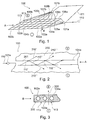
- Fig. 1 shows a perspective view of a Ionendosiervoriques without separator according to an exemplary embodiment of the present invention.
- Fig. 1 a plurality of power-conducting devices.
- the energy-directing device 102a, 103a, 104a, 105a, 106a, 102b, 103b, 104b, 105b, 106b, 107b, 108b, 109b of the ion-metering device 100 is designed as a network of at least one first energy-directing device 102a, 103a, 104a, 105a, 106a and at least a second power-conducting device 102b, 103b, 104b, 105b, 106b, 107b, 108b, 109b.
- the ion metering device 100 may, however, also have only a single first energy-conducting device 104a, which has an in Fig. 1 Sheathing device, not shown, is sheathed.
- optical fibers, optical fibers or fibers will be used as the first energy directing means 102a, 103a, 104a, 105a, 106a or as second energy-conducting device 102b, 103b, 104b, 105b, 106b, 107b, 108b, 109b, which form a network of energy-conducting devices for the ion-metering device 100.
- the first energy-conducting device 102a, 103a, 104a, 105a, 106a and the second energy-conducting device 102b, 103b, 104b, 105b, 106b, 107b, 108b, 109b are separated from one another and arranged at right angles to one another. This results in the rectangular openings 113, the rectangular meshes 113 or the grid openings 113 in the energy-conducting devices or in the ion-metering device 100.
- the first energy-conducting device 102a, 103a, 104a, 105a, 106a and the second energy-conducting device 102b, 103b, 104b, 105b, 106b , 107b, 108b, 109b are powered by the same energy source.
- the optical source described is the laser radiation 110, which transports an optical energy.
- different power control devices can also be powered from different energy sources. This may be the case, for example, when different properties are to be set in the separator by means of energy sources.
- the first energy 110 is transferred via the first energy supply device 101a and via the second energy supply device 101b into the first energy-conducting device 102a, 103a, 104a, 105a, 106a or into the second energy-conducting device 102b, 103b, 104b, 105b, 106b, 107b, 108b, 109b coupled.
- the first energy supply device 101a and the second energy supply device 101b are designed as beam splitters 101a, 101b, each of the plurality of first energy control devices 102a, 103a, 104a, 105a, 106a and the plurality of second energy control devices 102b, 103b, 104b, 105b, 106b, 107b, 108b, 109b of the Ionendosiervoriques 100 is energized.
- the first energy supply device 101a also decouples the energy for the second energy-conducting device 102b, 103b, 104b, 105b, 106b, 107b, 108b, 109b from the first energy supply device 101a via the stub 111.
- the first energy-conducting device 102a, 103a, 104a, 105a, 106a and for the second energy-conducting device 102b, 103b, 104b, 105b, 106b, 107b, 108b, 109b different forms of energy, such as optical energy and thermal energy, are used, if provided for the first energy-conducting device 102a, 103a, 104a, 105a, 106a and the second energy control device 102b, 103b, 104b, 105b, 106b, 107b, 108b, 109b
- corresponding physical energy control devices are, for example, optical conductors and thermal conductors.
- FIG Fig. 1 For better visibility of the energy directors 102a, 103a, 104a, 105a, 106a, 102b, 103b, 104b, 105b, 106b, 107b, 108b, 109b of the ion meter 100 is shown in FIG Fig. 1 the disconnecting means are not shown, which are in the openings 113 of the power conductors of the ion metering device 100 and / or the plurality of first power-conducting devices 102a, 103a, 104a, 105a, 106a and the plurality of second power-conducting devices 102b, 103b, 104b, 105b, 106b 107b, 108b, 109b.
- the ion-metering device 100 may be present when the separation device is destroyed.
- the separator or barrier layer in the openings 113 may be formed as a polymer which closes the openings 113 and thus together with the first energy-conducting device 102a, 103a, 104a, 105a, 106a and / or with the second energy-conducting device 102b, 103b, 104b, 105b, 106b, 107b, 108b, 109b forms an ion metering device 100 or ion metering layer 100.
- the first energy-conducting device 102a, 103a, 104a, 105a, 106a and / or the second energy-conducting device 102b, 103b, 104b, 105b, 106b, 107b, 108b, 109b are thus embedded, for example, in a photochemically decomposable polymer.
- the separator is made of photochemically decomposable polymer, by bringing the laser radiation to the separator, the photochemically decomposable polymer can be destroyed.
- the combination of the first energy-conducting device 102a, 103a, 104a, 105a, 106a and second energy-conducting device 102b, 103b, 104b, 105b, 106b, 107b, 108b, 109b with the separating device can also be referred to as a switchable separator 100 and used for a battery.
- the switchable separator 100 may dose, limit, alter, or even substantially completely block an ion flux around the energy director.
- the switchable separator 100 or the ion metering device 100 is a device by means of which the storability of batteries can be increased. Examples of arrangements of the ion metering device 100 in a battery 400 are shown in FIG 4 and FIG. 5 shown.
- the separator 100, and particularly the separator of the ion meter 100, can reduce the self-discharge in a battery 400. Self-discharge is often caused by undesirable side reactions within the battery 400 or cell 400, which result in ion transport through the electrolyte 405 present in the battery 400.
- the electrolyte is provided in the battery 400 as the ion transport device 405.
- the ion metering device 100 prevents ion transport caused by unwanted side reactions within the battery 400 by inhibiting such ion transport in the electrolyte 405 during the period of storage of the battery.
- Another embodiment of the invention as an ion-metering device allows metering of the ion current within the cell, which can then be increased or decreased by increasing or decreasing the energy input. In particular, in fault cases, such a current control with regard to increased security can be made possible.
- Ion dosing device 100 may inhibit the ion transport process within battery 400 through the electrolyte substantially for the duration of the battery storage.
- the ion transport barrier or separator is adjusted so that an ion transport through the Ionendosiervorides 100 and in particular through the separator therethrough corresponds to a predetermined size or is substantially unimpeded by the separator.
- the barrier effect of the separation device is destroyed, so that essentially through the openings 113 or through interspaces 113 between the sections of the first energy-directing means an ion transport can take place, which is not disturbed by the Ionendosiervortechnisch 100.
- Fig. 2 shows a sectional view through a Ionendosiervorraum 100 according to an exemplary embodiment of the present invention.
- the Fig. 2 shows the section through the first energy control device 104a of Fig. 1 , Which surrounded by the separator 200.
- the ion separator 200 is a photochemically decomposable polymer, as far as it is the supply of radiation as an energy form.
- the first energy-conducting device 104a or the optical fiber 104a is completely surrounded by the separating device 200, in particular by the barrier layer material 200.
- the separator 200 blocked in the present case the Fig.
- the sectional view of the Fig. 2 corresponds to a section along the cutting mark A of Fig. 1 ,
- the first energy 110 is coupled into the first energy-conducting device 104a.
- the first energy is a laser radiation 110 and thus an optical energy 110.
- the optical energy 110 is guided along the first energy-conducting device 104a in the interior of the energy-conducting device 104a by reflections at the boundary layer 201, so that the laser radiation 110 inside the energy-conducting device 104 as rays 110 ', 110 ", 110"' propagates.
- the loss energy in the form of radiation 210 ', 210 ", 210'” is coupled out of the first energy-directing device 104a into the separator 200 or barrier layer 200.
- a structure may be incorporated in an optical waveguide, for example a structure in a gradient fiber, such as microprisms or microcavels with a variable period.
- the decoupled energy 210 ', 210 ", 210"' with the separator 200 and the photochemically decomposable polymer 200 interact, whereby the separator 200 is destroyed or an ion conductivity the separator 200 is affected.
- the high energy output can be achieved by a physical adaptation of a waveguide or a characteristic impedance in the lateral surface of the waveguide.
- the separator 200 forms, together with the first energy-conducting device 102a, 103a, 104a, 105a, 106a, a thin layer or a layer system which can be introduced between both electrodes of a battery in addition to an electrolyte 405 present in a battery 400.
- the electrolyte 405 may also include an additional separator and then forms an electrolyte separator system 405.
- This separator present in the electrolyte separator system is substantially responsible for the amount of ion flow when the barrier action of the separator 200 is removed.
- the separator of the electrolyte / separator system may have a low ionic conductivity as compared with the ionic conductivity of the separator 200.
- the release layer 200 is inert to the materials used in the battery 400, i. H. it does not lead to side reactions and the formation of reaction products which could limit the functionality of the battery.
- the separator 200 has the property of changing its ion conductivity by an initial process so that the functionality of the battery can be established within a short time.
- the interruption of the ion transport paths caused by the separation device 200 is thereby destroyed by the initial process, so that the functionality of the battery can be established within a short time.
- the initial process or activation of the battery 400 causes the battery 400 to behave as if the ion meter 100 were absent. By a corresponding or else by another initial process, the barrier effect of the separator 200 can be restored.
- FIG. 12 shows a cross-sectional detail of the ion metering device 100 according to an exemplary embodiment of the present invention. It is a section of the cross section through the Ionendosiervorraum 100 along the cut mark B of Fig. 1 shown. Thus, the power supply 110 is in Fig. 3 not shown.
- the Fig. 3 FIG. 5 shows how the first energy-conducting device 102a, 103a, 104a is surrounded by the separating device 200, for example the polymer 200, and forms the ion-metering device 100.
- the intermediate spaces 113 between the first energy-conducting devices 102a, 103a, 104a are thereby closed by the separating device 200, so that substantially no ion transport between the region I and the region II along the symbolically illustrated arrow 300 or in the opposite direction is possible. Also, a transport past the energy-conducting device 102a, 103a, 104a, 105a, 106a, 102b, 103b, 104b, 105b, 106b, 107b, 108b, 109b or through the intermediate spaces 113 is blocked. Thus, separator 200 blocks ion transport between regions I and II and ion-dosing device 100. Separator 200 forms an ion transport barrier.
- the ion metering device 100 has a photochemically decomposable polymer layer 200 as a separator 200 or barrier layer 200.
- This polymer 200 is decomposed by introduction of energy, for example monochromatic radiation, for example by a laser, within a very short time or so damaged that the previously sealed ion transport paths 113 between the first energy control devices 102a, 103a, 104a are released. After the release of the transport paths 113 or the opening 113, an ion transport between the region I and the region II can take place.
- a discharge of the battery via an external circuit is possible and the battery 400 can be used. In this state, the battery 400 is activated.
- the resulting in the decomposition, remaining within the cell reaction products of photochemical decomposition should not adversely affect the battery behavior.
- a network of optical fibers 102a, 103a, 104a, 105a, 106a, 102b, 103b, 104b, 105b, 106b, 107b, 108b, 109b is introduced into the layer 100 brought in.
- the fibers 102a, 103a, 104a, 105a, 106a, 102b, 103b, 104b, 105b, 106b, 107b, 108b, 109b used have high losses with respect to radiation transport, i. H.
- a significant portion of the radiation 110 ', 110 ", 110”' is coupled into the polymer 200 through the fiber walls 201 during the reflective processes on the fiber walls 201, or may allow the optical fiber, e.g. by an introduced structure the defined coupling of a part of the radiation.
- the decoupled energy interacts with the polymer 200 and initiates in the polymer 200 the desired photochemical reaction, for example the decomposition of the polymer 200 or the surrounding separator 200.
- the separator or the battery 400 is enabled so that the ion transport is enabled and the battery operates substantially unrestricted.
- the effect of the separator 100 in the battery 400 is thus substantially canceled.
- Destroying and restoring the separator allows the realization of an ion switch. The ion switch is turned on when the separator 200 is broken and is turned off when the separator 200 is restored.
- the ion metering device 100 that is, the system polymer optical fiber 100, be selected so that, depending on the wavelength of the radiation used 110, the properties of the embedding material, ie the material of the barrier layer 200, change so that the Barrier layer 200, that is, substantially the surrounding material 200, is opened for the ion transport process.
- the barrier layer 100 can be restored, so that the openings 113 by the recovery of the Embedding material 200 to be closed again.
- the battery function can be switched on or switched off or even dosed.
- optical fibers 102a, 103a, 104a, 105a, 106a, 102b, 103b, 104b, 105b, 106b, 107b, 108b, 109b is also a thermal or electrical destruction or destruction of the barrier layer 100 and in particular the separator 200 conceivable.
- the first energy-directing device 102a, 103a, 104a, 105a, 106a is an optical energy-directing device for transporting an optical energy
- the second energy-directing device 102b, 103b, 104b, 105b, 106b, 107b, 108b, 109b is designed for thermal energy transport, for example by means of heating wires 102b, 103b, 104b, 105b, 106b, 107b, 108b, 109b.
- a barrier layer 200 and in particular the separator 200 could be opened or destroyed by supplying optical energy via the first energy-directing device 102a, 103a, 104a, 105a, 106a and then later by supplying the second energy via the second energy-directing device 102b, 103b, 104b , 105b, 106b, 107b, 108b, 109b or via an additional embedded network by means of thermal influencing of the material 200 and the separator 200 are closed again and thus the barrier effect can be restored.
- the Fig. 4 shows a first energy storage device according to an exemplary embodiment of the present invention.
- the energy storage device 400, the battery 400 or the accumulator 400 has a first electrode 401 or anode 401 and a second electrode 402 or cathode 402.
- a first active material 403 is arranged and at the second electrode, a second active material 404 is arranged.
- the active materials 403, 404 serve to release ions and generate electrical charges during the electrochemical reactions taking place in the active material.
- the Electric charges can be dissipated via the electrode terminals 406, 407 or current conductors 406, 407.
- the energy storage device 400 has three terminals, namely, the electrode terminals 407, 407 for dissipating the energy stored in the energy storage device 400 and the activation terminal 101a or the power supply 101a for activating the energy storage device 400. Only after the activation can be stored at the electrode terminals 406, 407 Energy to be dissipated.
- the battery is switched on or switched on by means of the ion metering device 100.
- an electrical circuit in an outer region of the battery 400 can be produced, which is powered by the battery 400. Ion transport within the battery 400 is provided by the electrolyte 405.
- the electrolyte 405 may also include a separator which is responsible for the size of the ion flux and forms an electrolyte / separator system 405 with the electrolyte.
- the separator 200 is inserted into the electrolyte 405, which separates the two regions I and II within the battery by the existing separator 200 from each other and prevents ion flow.
- Fig. 4 a battery in a storable state, which allows a long-term storage.
- the separating device 200 or barrier device 200 as part of the ion metering device 100 prevents the exchange of ions.
- Fig. 5 shows an alternative layer structure of a battery 400, in which the Ionendosiervoriques 100 is arranged with the separator 200 between the electrolyte 405 and the first active material 403. Even with this alternative positioning of the barrier layer 100, the barrier layer 100 essentially completely inhibits ion transport between the two regions I and II.
- the ion dosage device 100 present in the barrier layer 100 can be configured such that the ion transport is not completely prevented is controlled only by the amount of energy provided.
Landscapes
- Chemical & Material Sciences (AREA)
- Chemical Kinetics & Catalysis (AREA)
- Electrochemistry (AREA)
- General Chemical & Material Sciences (AREA)
- Engineering & Computer Science (AREA)
- Physics & Mathematics (AREA)
- Manufacturing & Machinery (AREA)
- Spectroscopy & Molecular Physics (AREA)
- General Engineering & Computer Science (AREA)
- High Energy & Nuclear Physics (AREA)
- Secondary Cells (AREA)
- Cell Separators (AREA)
Description
Die vorliegende Erfindung betrifft das technische Gebiet von Energiespeichervorrichtungen. Insbesondere betrifft die vorliegende Erfindung eine lonendosiervorrichtung für eine Energiespeichervorrichtung, ein Verfahren zum Herstellen einer Ionendosiervorrichtung für eine Energiespeichervorrichtung und eine Energiespeichervorrichtung.The present invention relates to the technical field of energy storage devices. More particularly, the present invention relates to an ion metering device for an energy storage device, a method of manufacturing an ion metering device for an energy storage device, and an energy storage device.
Batterien oder Akkumulatoren weisen eine Selbstentladung auf, die dazu führt, dass eine solche Batterie nur beschränkt lagerfähig ist. Die Selbstentladung kann bei heute kommerziell erhältlichen Zellen beispielsweise bei 1 % der Zellkapazität pro Monat liegen. Wegen dieser hohen Selbstentladung können solche Batterien nicht oder nur eingeschränkt in Fällen eingesetzt werden, in denen die Batterien vor ihrem Einsatz über einen langen Zeitraum eingelagert werden müssen, ohne dass die Batterien während der Lagerung weiter konditioniert werden. Somit erschwert die hohe Selbstentladung eine Lagerung von zehn Jahren und länger.Batteries or accumulators have a self-discharge, which means that such a battery is limited storable. For example, in today's commercially available cells, self-discharge may be at 1% of cell capacity per month. Because of this high self-discharge such batteries can not or only partially be used in cases where the batteries must be stored for a long period of time before use without the batteries being conditioned during storage. Thus, the high self-discharge makes storage of ten years or more difficult.
Es existieren Thermalbatterien, die jedoch nur eine kurze Betriebsdauer in der Größenordnung von wenigen Minuten erlauben.There are thermal batteries, but only allow a short operating time in the order of a few minutes.
Die Druckschrift
Die Druckschrift
Die Druckschrift
Die Druckschrift
Die Druckschrift
Die Druckschrift
Die Druckschrift
Es ist eine Aufgabe der Erfindung, eine verbesserte und sichere Energiespeicherung zu ermöglichen.It is an object of the invention to enable improved and safe energy storage.
Diese Aufgabe wird gemäß den Gegenständen der unabhängigen Patentansprüche gelöst. Weiterbildungen der Erfindung sind in den abhängigen Patentansprüchen angegeben.This object is achieved according to the subjects of the independent claims. Further developments of the invention are specified in the dependent claims.
Dementsprechend wird eine lonendosiervorrichtung für eine Batterie, ein Verfahren zum Herstellen einer lonendosiervorrichtung für eine Energiespeichervorrichtung und eine Energiespeichervorrichtung geschaffen.Accordingly, there is provided an ion metering device for a battery, a method of manufacturing an ion metering device for an energy storage device, and an energy storage device.
Eine Energiespeichervorrichtung kann nicht nur zum Speichern von Energie genutzt werden. Nach dem Aktivieren der Energiespeichervorrichtung setzt die Energiespeichervorrichtung die in ihr gespeicherte Energie frei und kann als Energieliefervorrichtung oder als Generator genutzt werden, beispielsweise um einen Stromkreis zu betreiben. Das Aktivieren kann Komponenten der Energiespeichervorrichtung, wie beispielsweise eine Ionendosiervorrichtung oder die in der Ionendosiervorrichtung enthaltene Trenneinrichtung, in einen elektrisch leitfähigen Zustand und/oder in einen ionisch leitfähigen Zustand versetzen.An energy storage device can not only be used to store energy. After activating the energy storage device, the energy storage device releases the stored energy in it and can be used as an energy delivery device or as a generator, for example to operate a circuit. The activation may place components of the energy storage device, such as an ion meter or the separator contained in the ion meter, in an electrically conductive state and / or in an ionically conductive state.
Gemäß einem Aspekt der vorliegenden Erfindung wird eine lonendosiervorrichtung für eine Batterie beschrieben. Die lonendosiervorrichtung weist eine erste Energieleiteinrichtung mit einer ersten Energiezufuhreinrichtung und einer Trenneinrichtung auf. Über die erste Energiezufuhreinrichtung kann der ersten Energieleiteinrichtung eine erste Energie für die lonendosiervorrichtung zugeführt werden.According to one aspect of the present invention, an ion metering device for a battery is described. The ion metering device has a first energy-conducting device with a first energy supply device and a separating device. Via the first energy supply device, the first energy-conducting device can be supplied with a first energy for the ion-metering device.
Die Trenneinrichtung ist eingerichtet, in einem ersten Zustand der Ionendosiervorrichtung, in dem keine Energie über die erste Energiezuführeinrichtung zugeführt wird, Ionen zu blockieren, die an der ersten Energieleiteinrichtung vorbei transportiert würden. In einem Beispiel weist die lonendosiervorrichtung die Energieleiteinrichtung und eine Trenneineinrichtung oder eine Barriereeinrichtung auf, beispielsweise eine Barriereschicht, die einen Ladungsträgertransport im Wesentlichen nur gestattet, wenn die Trenneinrichtung zerstört oder deren Ionenleitfähigkeit eingestellt worden ist.The separating device is set up, in a first state of the ion metering device in which no energy is supplied via the first energy supply device, to block ions which would be transported past the first energy-conducting device. In one example, the ion metering device includes the energy directing device and a separator or barrier device, such as a barrier layer, which essentially allows charge carrier transport only when the separator has been destroyed or its ionic conductivity has been adjusted.
Die erste Energieleiteinrichtung ist eingerichtet, die Transportrichtung der ersten Energie vorzugeben, um die erste Energie an eine im Wesentlichen vorgebbare Position der Trenneinrichtung innerhalb der lonendosiervorrichtung zu führen und an dieser Position die erste Energie innerhalb der lonendosiervorrichtung an die Trenneinrichtung abzugeben. In einem Beispiel gibt die Energieleiteinrichtung die Energie über die gesamte Länge der Energieleiteinrichtung ab. In einem anderen Beispiel kann die Energieabgabe mittels einer Auskoppeleinrichtung an einer bestimmten Position erreicht werden, beispielsweise durch die Strukturierung von Gradienten einer Gradienten-Lichtleitfaser.The first energy-conducting device is set up to predefine the transport direction of the first energy in order to lead the first energy to a substantially specifiable position of the separating device within the ion-metering device and at this position to deliver the first energy within the ion-metering device to the separating device. In one example, the energy director emits the energy over the entire length of the energy director. In another example, the energy output can be achieved by means of a decoupling device at a specific position, for example by structuring gradients of a gradient optical fiber.
In einem zweiten Zustand der Ionendosiervorrichtung, in dem die erste Energie über die erste Energiezuführeinrichtung zugeführt wird, bestimmt die Menge oder Größe der abgegebenen ersten Energie die Anzahl der von der Trenneinrichtung an der ersten Energieleiteinrichtung (102a, 103a, 104a, 105a, 106a) vorbei transportierten Ionen und/oder die Anzahl der von der Trenneinrichtung durchgelassenen Ionen. Somit bestimmt die Menge der abgegebenen ersten Energie die Ionenstromflussdichte durch die Trenneinrichtung, insbesondere die lonenstromflussdichte an der ersten Energieleiteinrichtung vorbei oder um die erste Energieleiteinrichtung herum. Indirekt bestimmt die aus einer Energiequelle zugeführte Energie die Menge der abgegebenen Energie und somit die Anzahl transportierter bzw. durchgelassener Ionen.In a second state of the ion metering device in which the first energy is supplied via the first power supply means, the amount of the outputted first energy exceeds the number of times the separator is applied to the first energy directing means (102a, 103a, 104a, 105a, 106a) transported ions and / or the number of transmitted by the separator ions. Thus, the amount of emitted first energy determines the ion current flux density through the separator, in particular the ion current density, past or around the first energy director. Indirectly, the energy supplied from an energy source determines the amount of energy delivered, and thus the number of ions transported or transmitted.
An der vorgebbaren Position der Ionendosiervorrichtung, zu der die erste Energie geführt wird, wirkt im Wesentlichen der Großteil der transportierten Energie auf die Trenneinrichtung ein. Die Trenneinrichtung kann passend zu der verwendeten Energieform gewählt werden, so dass die von der Energieleiteinrichtung freigegebene Energie mit der Trenneinrichtung zusammenwirkt, wechselwirkt oder von der Trenneinrichtung absorbiert wird. Das Wechselwirken oder das Absorbieren der Energie kann zu einer Wirkung in der Trenneinrichtung führen, die zu einer Veränderung der Transportfähigkeit für Ionen führt. Die Wahl der Trenneinrichtung, insbesondere die Wahl des Materials der Trenneinrichtung, kann somit von der verwendeten Energieform für die erste Energie abhängen. Dabei ist die Trenneinrichtung bzw. die Barriereschicht so ausgewählt, dass im Wesentlichen die gesamte über die Energieleiteinrichtung bereitgestellte Energie aufgenommen werden kann. Wird beispielsweise als erste Energie eine optische Energie in Form einer Laserstrahlung gewählt, so kommt als Trenneinrichtung innerhalb der Ionendosiervorrichtung ein photochemisch zersetzbares Polymer zum Einsatz. In einem weiteren Beispiel ist das photochemisch zersetzbare Polymer auf eine bestimmte Wellenlänge der Laserstrahlung abgestimmt, so dass eine maximale Zersetzung bei einer definierten Wellenlänge stattfindet.At the predeterminable position of the ion metering device, to which the first energy is guided, substantially the majority of the transported energy acts on the separation device. The separator may be selected to suit the type of energy used so that the energy released by the energy director interacts with the separator, interacts or is absorbed by the separator. The interaction or absorption of the energy can lead to an effect in the separator, which leads to a change in the transportability of ions. The choice of the separating device, in particular the choice of the material of the separating device, can thus depend on the type of energy used for the first energy. In this case, the separating device or the barrier layer is selected such that substantially all the energy provided via the energy-conducting device can be absorbed. If, for example, an optical energy in the form of a laser radiation is selected as the first energy, a photochemically decomposable polymer is used as the separating device within the ion metering device. In another example, the photochemically decomposable polymer is tuned to a particular wavelength of the laser radiation so that maximum decomposition occurs at a defined wavelength.
Die Energie kann über die gesamte Länge der Energieleiteinrichtung abgegeben werden. Durch spezielle Maßnahmen, wie das Vorsehen einer Ummantelung, kann die Energieabgabe an bestimmten Positionen, an denen keine Energieabgabe erwünscht wird, unterbunden werden. Auch kann die Energieabgabe durch geeignete Modifikationen der Energieleiteinrichtung, wie das Vorsehen einer Strukturierung, gefördert werden. In einem Beispiel werden in eine Gradienten-Lichtleitfaser Strukturen eingebracht, die eine partielle Auskopplung der Strahlung an definierten Positionen hervorrufen. Durch eine solche Modifikation kann die Position bestimmt werden, an der die erste Energie an die Trenneinrichtung abgegeben wird.The energy can be dissipated over the entire length of the energy control device. By special measures, such as the provision of a sheath, the energy output can be prevented at certain positions where no energy release is desired. Also, the energy output can be promoted by appropriate modifications of the energy directing device, such as the provision of structuring. In one example, structures are introduced into a gradient optical fiber, which cause a partial decoupling of the radiation at defined positions. By such a modification, the position can be determined, at which the first energy is delivered to the separator.
Die Trenneinrichtung mag eingerichtet sein, eine Anzahl von Ionen, die um die erste Energieleiteinrichtung herum transportiert und/oder blockiert werden, über die zugeführte Energie zu kontrollieren.The separator may be configured to control a number of ions that are transported and / or blocked around the first energy director via the supplied energy.
Unter "Herumtransportieren" mag auch verstanden werden, dass Ionen an der Energieleiteinrichtung vorbeitransportiert werden, insbesondere, dass die Ionen durch Zwischenräume, die von der Energieleiteinrichtung oder von einer Vielzahl von Energieleiteinrichtungen gebildet werden, hindurch transportiert werden.By "transport around" it may also be understood that ions are transported past the energy directing device, in particular that the ions are transported through gaps formed by the energy directing device or by a plurality of energy directing devices.
Gemäß einem weiteren Aspekt der vorliegenden Erfindung wird ein Verfahren zum Herstellen einer lonendosiervorrichtung für eine Energiespeichervorrichtung beschrieben. Das Verfahren weist das Bereitstellen einer ersten Energieleiteinrichtung und einer ersten Energiezufuhreinrichtung auf, wobei die erste Energiezufuhreinrichtung an der ersten Energieleiteinrichtung angeordnet sein kann. Über die erste Energiezufuhreinrichtung ist der ersten Energieleiteinrichtung eine erste Energie zuführbar. Somit kann die erste Energiezufuhreinrichtung das Einkoppeln einer ersten Energie in die erste Energieleiteinrichtung ermöglichen, beispielsweise das Einkoppeln aus einer Energiequelle.According to a further aspect of the present invention, a method of manufacturing an ion metering device for an energy storage device is described. The method has the provision of a first energy-conducting device and a first energy supply device, wherein the first energy supply device can be arranged on the first energy-conducting device. A first energy can be supplied to the first energy-conducting device via the first energy supply device. Thus, the first energy supply device can enable the coupling of a first energy into the first energy-conducting device, for example the coupling from an energy source.
Die bereitgestellte erste Energieleiteinrichtung wird mit einer Trenneinrichtung umgeben, mittels derer ein Ionentransport verhindert werden kann, oder aber die erste Energieleiteinrichtung wird in die o.g. Trenneinrichtung eingebettet. Die Energiezufuhreinrichtung in Kombination mit der Energieleiteinrichtung und der Trenneinrichtung bilden die lonendosiervorrichtung. In einem Beispiel wird die Energieleiteinrichtung so in einer Ebene verlegt, dass durch die Form der Verlegung Öffnungen zwischen der Energieleiteinrichtung entstehen. Diese Öffnungen mögen beispielsweise von einer Vielzahl erster Energieleiteinrichtungen durch paralleles oder gitterförmiges Anordnen von zumindest zwei Energieleiteinrichtungen und/oder durch ein schleifenförmiges Verlegen von einer einzigen ersten Energieleiteinrichtung entstehen. Die Öffnungen, welche in Zwischenräumen der ersten Energieleiteinrichtung vorhanden sind, werden mit der Trenneinrichtung innerhalb der lonendosiervorrichtung verschlossen. Die lonendosiervorrichtung bzw. deren Trenneinrichtung kann als Trennmedium oder Barriereschicht für eine Ionentransporteinrichtung genutzt werden, z.B. für einen Elektrolyten innerhalb einer Batterie. Der Elektrolyt mag in Verbindung mit einem Separator genutzt werden. Die lonendosiervorrichtung bzw. deren Trenneinrichtung kann wegen ihrer Trennwirkung einen Ionentransport im Wesentlichen blockieren, insbesondere, wenn die lonendosiervorrichtung und/oder die Trenneinrichtung nicht mit der Ionentransporteinrichtung reagiert. In einem Beispiel kann innerhalb der lonendosiervorrichtung eine vorgebbare Anzahl an Ionen um die Energieleiteinrichtung herumgeführt oder an der Energieleiteinrichtung vorbei geführt werden. Die Anzahl der Ionen, die innerhalb der lonendosiervorrichtung transportiert werden, wird dabei durch die durch die Energieleiteinrichtung an die Trenneinrichtung abgegebene Energiemenge bzw. die Form der zugeführten Energie bestimmt. Zum Führen der Ionen kann die lonendosiervorrichtung Ionen von einer Ionentransporteinrichtung empfangen oder Teil der lonentransporteinrichtung sein. Zum Führen der Ionen mag ein einem Beispiel ein lonenkanal genutzt werden.The provided first energy-conducting device is surrounded by a separating device, by means of which an ion transport can be prevented, or the first energy-conducting device is embedded in the above-mentioned separating device. The energy supply device in combination with the energy-conducting device and the separating device form the ion-metering device. In one example, the power-conducting device is laid in a plane such that, due to the shape of the routing, openings are formed between the energy-conducting device. These openings may be, for example, of a plurality of first power-conducting devices by arranging at least two power-conducting devices in parallel or in a grid, and / or by laying a single first one in a loop Energy control arise. The openings, which are present in intermediate spaces of the first energy-conducting device, are closed by the separating device within the ion-metering device. The ion metering device or its separating device can be used as a separation medium or barrier layer for an ion transport device, for example for an electrolyte within a battery. The electrolyte may be used in conjunction with a separator. Because of its separating action, the ion metering device or its separating device can substantially block ion transport, in particular if the ion metering device and / or the separating device does not react with the ion transport device. In one example, a predeterminable number of ions can be guided around the energy-conducting device or led past the energy-conducting device within the ion-metering device. The number of ions transported within the ion metering device is determined by the amount of energy delivered to the separator by the energy directing means or the form of energy supplied. For guiding the ions, the ion-metering device may receive ions from an ion transport device or be part of the ion transport device. For example, an ion channel may be used to guide the ions.
Das Umgeben der ersten Energieleiteinrichtung innerhalb der Ionendosiervorrichtung mit der Trenneinrichtung erfolgt der Art, dass die Trenneinrichtung eingerichtet ist, in einem ersten Zustand, in dem keine Energie über die erste Energiezuführeinrichtung zugeführt wird, Ionen, die an der ersten Energieleiteinrichtung vorbei transportiert würden, zu blockieren, beispielsweise durch Blockieren einer Ionentransporteinrichtung oder durch das Dosieren der Anzahl beweglicher Ionen in der Trenneinrichtung. Für die Zuführbarkeit der ersten Energie wird die erste Energiezuführeinrichtung mit der ersten Energieleiteinrichtung verbunden. Die erste Energieleiteinrichtung ist eingerichtet, die Transportrichtung der ersten Energie vorzugeben, um die erste Energie an eine vorgebbare Position der Trenneinrichtung innerhalb der lonendosiervorrichtung zu führen und an dieser Position die erste Energie an die Trenneinrichtung abzugeben.Surrounding the first energy-conducting device within the ion-metering device with the separating device is such that the separating device is set up to block ions that would have been transported past the first energy-conducting device in a first state in which no energy is supplied via the first energy supply device For example, by blocking an ion transport device or by dosing the number of mobile ions in the separator. For the feedability of the first energy, the first energy supply device is connected to the first energy-conducting device. The first energy-conducting device is set up to predefine the transport direction of the first energy in order to supply the first energy to a predeterminable position of the separating device to lead within the Ionendosiervorrichtung and deliver the first energy to the separator at this position.
Ferner erfolgt das Umgeben der ersten Energieleiteinrichtung mit der Trenneinrichtung so, dass in einem zweiten Zustand, in dem die erste Energie über die erste Energiezuführeinrichtung zugeführt wird, die Menge der abgegebenen ersten Energie die Anzahl der von der Trenneinrichtung an der ersten Energieleiteinrichtung vorbei transportierten Ionen bestimmt und/oder die Anzahl der von der Trenneinrichtung durchgelassenen Ionen bestimmt.Furthermore, the surrounding of the first energy-conducting device with the separating device takes place in such a way that, in a second state in which the first energy is supplied via the first energy supply device, the quantity of emitted first energy determines the number of ions transported past the separating device at the first energy-conducting device and / or determines the number of ions transmitted by the separator.
Durch den Wechsel von dem ersten Zustand in den zweiten Zustand und umgekehrt kann die lonendosiervorrichtung zwischen einem blockierten Zustand und einem leitfähigen Zustand geschaltet werden. Der erste Zustand mag einem Ruhezustand oder Lagerzustand entsprechen. Der zweite Zustand mag einem aktivierten Zustand entsprechen.By changing from the first state to the second state and vice versa, the ion metering device can be switched between a blocked state and a conductive state. The first state may correspond to a rest state or storage state. The second state may correspond to an activated state.
Gemäß einem weiteren Aspekt der vorliegenden Erfindung wird eine Energiespeichervorrichtung, beispielsweise eine Batterie oder ein Akkumulator beschrieben. Die Energiespeichervorrichtung weist eine erste Elektrode, eine zweite Elektrode und eine Ionentransporteinrichtung sowie die erfindungsgemäße lonendosiervorrichtung auf. Die lonendosiervorrichtung steht mit der Ionentransporteinrichtung in Kontakt, um eine von der Ionentransporteinrichtung transportierte Anzahl an Ionen zu kontrollieren. Beim Kontrollieren kann die Anzahl der transportierten Ionen über die zugeführte Energiemenge gesteuert werden. In einem Beispiel kann durch den Wechsel zwischen dem ersten und zweiten Zustand ein Schalten der lonendosiervorrichtung realisiert werden. Beim Schalten mag es auf die Anzahl der transportierten Ionen im Wesentlichen nicht ankommen, sondern nur darauf, ob Ionen transportiert werden und möglicherweise, ob die Anzahl transportierter Ionen einen vorgegebenen Schwellwert übersteigt. Die lonendosiervorrichtung ist zwischen der ersten Elektrode und der zweiten Elektrode angeordnet. In einem Beispiel kann die erste Elektrode eine Anode und die zweite Elektrode eine Kathode sein und die Ionentransporteinrichtung kann ein Elektrolyt, auch in Verbindung mit einem Separator sein.According to another aspect of the present invention, an energy storage device, such as a battery or a rechargeable battery, is described. The energy storage device has a first electrode, a second electrode and an ion transport device and the ion metering device according to the invention. The ion metering device is in contact with the ion transport device to control a number of ions transported by the ion transport device. When controlling, the number of ions transported can be controlled by the amount of energy supplied. In one example, by switching between the first and second states, switching of the ion metering device can be realized. During switching, the number of ions transported may essentially not matter, but only whether ions are transported and possibly whether the number of ions transported exceeds a predetermined threshold. The ion metering device is disposed between the first electrode and the second electrode. In one For example, the first electrode may be an anode and the second electrode may be a cathode, and the ion transport device may be an electrolyte, also in conjunction with a separator.
Die Energiespeichervorrichtung oder die Energiefreigabevorrichtung weist zumindest drei Anschlüsse auf, nämlich die erste Elektrode, die zweite Elektrode und die Energiezufuhreinrichtung zum Aktivieren und/oder zum Kontrollieren der Inendosiereinrichtung bzw. der darin enthaltenen Trenneinrichtung. Die der Ionendosiervorrichtung zugeführte Energie kann im Wesentlichen ohne Umwandlung in eine andere Energieform auf die Trennvorichtung einwirken. Beispielsweise wirkt die zugeführte Lichtenergie direkt auf die Trennvorrichtung ein. Ähnlich einem Feldeffekttransistor, wird die Leitfähigkeit des Materials der Trenneinrichtung durch die Energiezufuhr beeinflusst Die Energiezufuhreinrichtung kann als Steuereinrichtung für den zwischen den Elektroden transportierten lonenstrom angesehen werden. Der Ionentransistor mag in einem Beispiel im Wesentlichen innerhalb einer Spannungsquelle oder Energiespeichervorrichtung wirken. Beispielsweise wird die Ionenleitfähigkeit des Materials der Trenneinrichtung mittels Lichtenergie oder mittels der Energie eines elektrischen Feldes gezielt verändert. Folglich kann die erfindungsgemäße Energiespeichervorrichtung als ein lonentransistor bezeichnet werden. Die Trenneinrichtung kann als dünne Folie oder als ein Schichtensystem ausgeführt sein. Die Eigenschaft der Folie oder Membran kann zur lonenschaltung und Ionendosierung mittels eines elektrischen Feldes beeinflusst werden. Die lonendosiervorrichtung kann zum Dosieren oder Schalten von lonenströmen genutzt werden. In einem Beispiel kann die Ionenleitfähigkeit der Folie oder der Membran über die Beeinflussung eines lonenkanals mittels eines elektrostatischen Feldes moduliert und auf diese Weise verändert werden. Insbesondere mag ein feldmodulierter polymerer lonenkanal einsetzbar sein, der durch die Kombination von Monomeren, z.B. Alamethicin und Gramicidin, ensteht, und durch ein angelegtes elektrostatisches Feld assembliert, deformiert oder zerstört werden kann, wodurch sich die Ionenleitfähigkeit modulieren lässt.The energy storage device or the energy release device has at least three terminals, namely the first electrode, the second electrode and the energy supply device for activating and / or controlling the internal metering device or the separating device contained therein. The energy supplied to the ion metering device can act on the separation device essentially without conversion into another form of energy. For example, the supplied light energy acts directly on the separation device. Similar to a field effect transistor, the conductivity of the material of the separator is influenced by the energy supply. The energy supply means can be considered as a control means for the ion current transported between the electrodes. The ion transistor in one example may operate substantially within a voltage source or energy storage device. For example, the ionic conductivity of the material of the separator is selectively changed by means of light energy or by means of the energy of an electric field. Consequently, the energy storage device according to the invention may be referred to as an ion transistor. The separating device can be designed as a thin film or as a layer system. The property of the film or membrane can be influenced for ion switching and ion metering by means of an electric field. The Ionendosiervorrichtung can be used for dosing or switching of ion streams. In one example, the ionic conductivity of the film or membrane may be modulated and altered by influencing an ion channel by means of an electrostatic field. In particular, a field modulated polymeric ion channel may be useful which is formed by the combination of monomers, eg, alamethicin and gramicidin, and which can be assembled, deformed, or disrupted by an applied electrostatic field, thereby modulating ionic conductivity.
Gemäß einem weiteren Aspekt der vorliegenden Erfindung wird ein Flugkörper angegeben, welcher eine Energiespeichervorrichtung mit der lonendosiervorrichtung aufweist.According to a further aspect of the present invention, a missile is disclosed, which has an energy storage device with the Ionendosiervorrichtung.
Eine lange Lagerfähigkeit ist insbesondere im militärischen Anwendungsbereich gefordert. Beispielsweise wird eine lange Lagerfähigkeit von Batterien oder Akkumulatoren gefordert, welche in militärischen Flugkörpern verbaut werden. Eine lange Lagerfähigkeit von Batterien kann mit sog. Thermalbatterien erreicht werden, die bis zu ihrem Einsatz elektrisch inaktiv sind, da der Elektrolyt, insbesondere der Separator, in der Zelle erst bei einer Aktivierung der Batterie, der Zelle oder des Akkumulators ionisch leitend wird, wodurch die elektrische Funktionsfähigkeit der Batterie hergestellt werden kann. Die ionische Leitfähigkeit kann durch die unkontrollierte Erhitzung des Elektrolyten hergestellt werden, beispielsweise mittels eines pyrotechnischen Treibsatzes. Eine Thermalbatterie weist lediglich eine kurze Betriebsdauer in der Größenordnung von wenigen Minuten auf, da ein Elektrolyt, der durch pyrotechnische Erhitzung aktiviert wird, zeitlich nur begrenzt für Ionen leitfähig bleibt. Außerdem weisen Thermalbatterien im Vergleich zu anderen Batteriesystemen, z.B. zu Li-Ionen-Zellen (Lithium-Ionen-Zellen), eine relativ geringe spezifische Energiedichte auf. Die Energiedichte ist jedoch ein Parameter, der in einer Vielzahl von Anwendungen eine zentrale Rolle spielt. Denn beispielsweise nimmt der Energiebedarf von einzelnen Verbrauchern oder auch die Anzahl von Verbrauchern in einer Vielzahl von Anwendungen stetig zu.A long shelf life is required especially in the military field of application. For example, a long shelf life of batteries or accumulators is required, which are installed in military missiles. A long shelf life of batteries can be achieved with so-called thermal batteries, which are electrically inactive until their use, since the electrolyte, in particular the separator, becomes ionic conductive in the cell only upon activation of the battery, the cell or the accumulator the electrical functioning of the battery can be made. The ionic conductivity can be produced by the uncontrolled heating of the electrolyte, for example by means of a pyrotechnic propellant. A thermal battery has only a short operating time in the order of a few minutes, since an electrolyte which is activated by pyrotechnic heating, limited in time remains conductive for ions. In addition, thermal batteries have, compared to other battery systems, e.g. to Li-ion cells (lithium-ion cells), a relatively low specific energy density. However, energy density is a parameter that plays a central role in a variety of applications. For example, the energy demand of individual consumers or the number of consumers in a variety of applications is steadily increasing.
Des Weiteren kann es in Batteriesystemen zu Sicherheitsproblemen kommen, welche beispielsweise durch zu hohe Stromflüsse verursacht werden, welche dementsprechend hohe ionische Ströme im Inneren der Batterie verursachen. Dabei kann es in einigen Batteriekonfigurationen zur Beschädigung von Grenzschichten kommen und in der Folge beispielsweise zu einer Dendritenbildung und zur thermischen Beschädigung der Zelle.Furthermore, safety problems can occur in battery systems which are caused, for example, by excessive current flows, which accordingly cause high ionic currents inside the battery. In some battery configurations, this can lead to the damage of boundary layers and consequently, for example, to dendritic formation and thermal damage to the cell.
Mit Hilfe der Trenneinrichtung kann eine Energiespeichervorrichtung in der die lonendosiervorrichtung eingesetzt wird, nach Bedarf aktiviert werden, auch nach einer langen Zeit. Es kann als ein Aspekt der vorliegenden Erfindung angesehen werden, die ionische Leitfähigkeit einer Trenneinrichtung, Barriereschicht oder eines Separators,z.B. einer Separatormembran, mittels zugeführter Energie zu kontrollieren, zu ändern, zu steuern oder zu dosieren. Die ionische Leitfähigkeit kann beispielsweise in Abhängigkeit von der zugeführten Energiemenge bzw. der zugeführten Energieform kontrolliert werden, beispielsweise in Abhängigkeit der Strahlungsintensität, Wellenlänge und Einstrahldauer. Die Trenneinrichtung oder die Barriereschicht kann in einer Separatoreinrichtung oder Separatormembran eingebaut sein, die in einer Energiespeichervorrichtung vorhandenen ist, um beispielsweise Aktivmaterialien voneinander zu trennen. Alternativ kann die Trenneinrichtung als eine zusätzliche Barriereschicht zu der Separatormembran einer Batterie oder eines Akkumulators angewendet werden. Somit kann die Ionendosiervorrichtung mit ihrer Trenneinrichtung als ein schaltbarer Separator oder als ein steuerbarer Separator angesehen werden. Insbesondere kann eine entsprechende lonendosiervorrichtung mit der zugehörigen Trenneinrichtung auch als schaltbarer Separator für eine Batterie oder für einen Akkumulator bezeichnet werden.With the aid of the separating device, an energy storage device in which the ion metering device is used can be activated as required, even after a long time. It may be considered as one aspect of the present invention to control the ionic conductivity of a separator, barrier layer or separator, e.g. a separator membrane to control by means of supplied energy, to change, to control or to meter. The ionic conductivity can be controlled, for example, as a function of the amount of energy supplied or the supplied energy form, for example as a function of the radiation intensity, wavelength and irradiation time. The separator or barrier layer may be incorporated in a separator or separator membrane provided in an energy storage device to separate, for example, active materials. Alternatively, the separator may be applied as an additional barrier layer to the separator membrane of a battery or accumulator. Thus, the Ionendosiervorrichtung can be viewed with their separator as a switchable separator or as a controllable separator. In particular, a corresponding ion metering device with the associated separating device can also be referred to as a switchable separator for a battery or for a rechargeable battery.
Die lonendosiervorrichtung, der schaltbare Separator, die zusätzliche Barriereschicht der lonendosiervorrichtung oder die zusätzliche Separatormembran kann ein Netz aus Energieleiteinrichtungen aufweisen, beispielsweise ein Netz aus Lichtleitfasern. Jede einzelne der verwendeten Energieleiteinrichtungen kann eine hohe Verlustleistung für den Transport der gewählten Energie in Transportrichtung aufweisen, so dass ein Großteil der Energie in einen Außenbereich der Energieleiteinrichtung abgegeben wird. Wegen dieser hohen Verlustleistung kann im Wesentlichen ein Großteil der transportieren Energie, von der Energieleiteinrichtung an die Trenneinrichtung abgegeben werden. Die Energie kann von einer optischen Strahlung, einer Mikrowelle, einer beliebigen anderen elektromagnetischen Strahlungsform, einem elektrischen Strom, einem magnetischen Feld, einem elektrischen Feld, einem elektrostatischen Feld, einem magnetischen Feld oder auch als thermische Strahlung transportiert werden. In einem Beispiel, bei Einbringung von Strahlungsenergie im optischen Bereich, erfolgt die Energieabgabe von der Energieleiteinrichtung an die Trenneinrichtung der lonendosiervorrichtung über die in eine Gradienten-Lichtleitfaser eingebrachten Strukturen, die zum verstärkten Auskoppeln eines Teils der Strahlung an der Position führen, an der die Strukturen angeordnet sind. In einem anderen Beispiel, bei Teiltransparenz der Lichtleitfaser, erfolgt die Auskopplung der Strahlung über Verluste bei der Reflexion der Strahlung im inneren des Lichtleiters. In noch einem anderen Beispiel erfolgt die Auskopplung über ein elektrisches Feld.The ion metering device, the switchable separator, the additional barrier layer of the ion metering device or the additional separator membrane may comprise a network of energy-conducting devices, for example a network of optical fibers. Each of the energy control devices used can have a high power loss for the transport of the selected energy in the transport direction, so that a large part of the energy is discharged into an outer region of the energy-conducting device. Because of this high power dissipation, substantially a majority of the transported energy can be delivered from the energy directing device to the separator. The energy can be from an optical Radiation, a microwave, any other electromagnetic radiation form, an electric current, a magnetic field, an electric field, an electrostatic field, a magnetic field or as thermal radiation are transported. In one example, with application of radiant energy in the optical domain, energy delivery from the energy director to the separator of the ion doser occurs through structures introduced into a gradient optical fiber which result in more coupling of a portion of the radiation at the position where the structures are located are arranged. In another example, with partial transparency of the optical fiber, the coupling out of the radiation takes place via losses in the reflection of the radiation in the interior of the optical waveguide. In yet another example, the extraction is via an electric field.
Die Trenneinrichtung oder Barriereschicht kann die Energieleiteinrichtung ummanteln, so dass die Energieleiteinrichtung im Wesentlichen vollständig von der Trenneinrichtung umgeben ist. Die bei einer schleifenförmigen Verlegung oder bei einer gitterförmigen Verlegung der Energieleiteinrichtung entstehende Öffnungen mögen somit im Wesentlichen mit der Trenneinrichtung verschlossen werden. Die Kombination aus Energieleiteinrichtung und Trenneinrichtung kann eine Ionendosiervorrichtung formen, die in eine Energiespeichervorrichtung eingebracht werden kann. Jede andere dreidimensionale Form neben der Schichtform ist ebenfalls denkbar. Ein Beispiel für eine Trenneinrichtung kann ein photochemisch zersetzbares Polymer sein. Dieses kann auf die Wellenlänge einer bestimmten Laserstrahlung reagieren und zersetzt werden. Im Falle eines photochemisch zersetzbaren Polymers kann eine Lichtleitfaser oder ein optischer Leiter als Energieführeinrichtung genutzt werden, um die Laserstrahlung durch die Trenneinrichtung der lonendosiervorrichtung zu führen. In weiteren Ausführungsbeispielen sind auch andere Strahlungsformen denkbar, wie sichtbares Licht, UV (Ultraviolett)-Strahlung, und IR (Infrarot)-Strahlung, die mit den entsprechenden Leitern geführt werden. Die Form der Führung kann die Wirkung der photochemischen Reaktion erhöhen. In dem Fall, dass die lonendosiervorrichtung aus einer Lichtleitfaser und einem photochemisch zersetzbaren Polymer gebildet wird, kann die Lichtleitfaser mit dem photochemisch zersetzbaren Polymer ummantelt sein bzw. mit einem Polymer, dessen chemisch-physikalische Eigenschaften mittels spezifischer Strahlung definiert eingestellt werden kann. Als chemisch-physikalische Eigenschaft des Polymers kann die Ionenleitfähigkeit eines solchen Polymers bezeichnet werden. Ein Polymer, dessen chemisch-physikalische Eigenschaft mittels spezifischer Strahlung gezielt eingestellt oder dosiert werden kann bzw. ein photochemisch zersetzbares Polymer ist ein Beispiel für die Trenneinrichtung einer Ionendosiervorrichtung, die mit einer entsprechenden Energieform wechselwirkt, welche in der Energieleiteinrichtung geführt wird und aus ihr austritt.The separating device or barrier layer can encase the energy-conducting device, so that the energy-conducting device is substantially completely surrounded by the separating device. The resulting in a loop-like installation or in a grid-like installation of the energy control device openings may thus be substantially closed with the separator. The combination of energy directing means and separating means may form an ion metering device which may be incorporated into an energy storage device. Any other three-dimensional shape besides the layer form is also conceivable. An example of a separator may be a photochemically decomposable polymer. This can react to the wavelength of a specific laser radiation and be decomposed. In the case of a photochemically decomposable polymer, an optical fiber or an optical conductor can be used as an energy guiding device to guide the laser radiation through the separating device of the ion metering device. In other embodiments, other forms of radiation are conceivable, such as visible light, UV (ultraviolet) radiation, and IR (infrared) radiation, which are guided with the corresponding conductors. The form of leadership can enhance the effect of the photochemical reaction increase. In the case that the Ionendosiervorrichtung is formed of an optical fiber and a photochemically decomposable polymer, the optical fiber may be coated with the photochemically decomposable polymer or with a polymer whose chemical-physical properties can be set defined by means of specific radiation. As the chemical-physical property of the polymer, the ionic conductivity of such a polymer may be referred to. A polymer whose chemical-physical property can be deliberately adjusted or metered by means of specific radiation or a photochemically decomposable polymer is an example of the separation device of an ion-metering device which interacts with a corresponding energy form which is guided in and out of the energy-directing device.
Aus einer Energiequelle wird der Energieleiteinrichtung Energie zugeführt. Die Kombination des verwendeten Materials für die Trennvorrichtung und die eingesetzte Energiequelle und damit die genutzte erste Energieleiteinrichtung und/oder die zweite Energieleiteinrichtung mag im optischen Fall so gewählt werden, dass die Photonenergie der eingesetzten Laserstrahlung, beispielsweise eines Eximerlasers, größer als die Bindungsenergie der kovalenten Bindungen im Polymer der Trenneinrichtung ist.From an energy source of the power control device energy is supplied. The combination of the material used for the separation device and the energy source used and thus the used first energy control device and / or the second energy control device may be selected in the optical case so that the photon energy of the laser radiation used, for example, an eximer laser, greater than the binding energy of the covalent bonds in the polymer of the separator.
Als Polymer kann ein Hydroxy-substituiertes Niederalkylacrylat oder -methyacrylat zum Einsatz kommen, das mit Ethylglykoldimethaacrylat, Ethylenglykoldimethacrylat oder Divinylbenzol vernetzt ist. Ferner kann ein vernetztes Polymer mit folgenden kovalenten Hauptbindungen eingesetzt werden, z.B. Kohlenstoff-Kohlenstoff, Kohlenstoff-Stickstoff, Kohlenstoff-Sauerstoff, Silizium-Kohlenstoff und/oder Silizium-Sauerstoff. Ein vernetztes Polymer ist im Wesentlichen ein dreidimensionales Netzwerk.The polymer used may be a hydroxy-substituted lower alkyl acrylate or methacrylate which is crosslinked with ethyl glycol dimethacrylate, ethylene glycol dimethacrylate or divinylbenzene. Further, a crosslinked polymer having the following main covalent bonds can be used, e.g. Carbon-carbon, carbon-nitrogen, carbon-oxygen, silicon-carbon and / or silicon-oxygen. A crosslinked polymer is essentially a three-dimensional network.
Die Polymere werden insbesondere so ausgewählt, dass weder die verwendeten Polymere noch die entstehenden Zersetzungsprodukte mit den Inhaltsstoffen bzw. den Komponenten des Energiespeichervorrichtung so reagieren, dass eine solche Reaktion und/oder dabei entstehende Reaktionsprodukte nachteilig hinsichtlich der Funktionalität des Energiespeichers sind, beispielsweise die lonenleitfähigkeit beeinträchtigen.The polymers are especially selected so that neither the polymers used nor the resulting decomposition products with the ingredients or react the components of the energy storage device so that such a reaction and / or resulting reaction products are detrimental to the functionality of the energy storage, for example, affect the ion conductivity.
Die Effektivität der Strahlung beim Zersetzen mag erhöhbar sein, wenn eine kohärente Strahlung eingesetzt wird.The effectiveness of the radiation in decomposition may be heightenable when coherent radiation is used.
In einem weiteren Beispiel kann die lonenleitfähigkeit der Trenneinrichtung durch ein durch eine Energiezufuhreinrichtung und eine Energieleiteinrichtung eingebrachtes elektromagnetisches Feld gezielt eingestellt werden. Durch die Energiezuführung kann die lonendosiervorrichtung zum Schalten oder Steuern von Ionenströmen genutzt werden. Für die Trenneinrichtung können Folien oder andere dünnen Schichtsysteme eingesetzt werden. Diese erlauben bei Energiezufuhr einen lonenstrom und sind chemisch beständig und/oder inert gegenüber denjenigen Stoffen, die mit der Trenneinrichtung in Kontakt kommen und die ein Bestandteil der Energiespeichervorrichtung sind.In another example, the ion conductivity of the separator may be selectively adjusted by an electromagnetic field introduced by an energy supply device and an energy directing device. Due to the energy supply, the ion metering device can be used for switching or controlling ion currents. Foils or other thin layer systems can be used for the separating device. These allow an ion current when energized and are chemically resistant and / or inert to those substances that come into contact with the separator and that are a part of the energy storage device.
Mittels der beschriebenen Trenneinrichtung kann eine Energiespeichervorrichtung gegen Selbstentladung geschützt werden und die Zeit, bis die Energie aus der Energiespeichervorrichtung geliefert werden soll, kann erhöht werden. Folglich kann die Lagerdauer oder der Bereitstellungszeitraum erhöht werden. Durch das gezielte Steuern oder das gezielte Dosieren von transportierten Ionen in der Trenneinrichtung kann es auch möglich sein, einen Innenwiderstand der Energiespeichervorrichtung zu verändern, so dass eine gesteuerte Energiequelle realisierbar wird. Denkbar ist beispielsweise eine Steuerung oder Regulierung der fließenden elektrischen Ströme im Fehlerfall durch eine Dosierung des lonenstroms innerhalb der Energiespeichervorrichtung.By means of the described disconnecting device, an energy storage device can be protected against self-discharge and the time until the energy is to be supplied from the energy storage device can be increased. Consequently, the storage period or the provision period can be increased. By the targeted control or the targeted metering of transported ions in the separating device, it may also be possible to change an internal resistance of the energy storage device so that a controlled energy source can be realized. It is conceivable, for example, a control or regulation of the flowing electric currents in case of failure by dosing the ion current within the energy storage device.
Gemäß einem weiteren Aspekt der vorliegenden Erfindung ist die Ionendosiervorrichtung als Sicherungsvorrichtung für einen möglichen Fehlerfall eingerichtet. Dabei wird im Falle eines Fehlers im Energiespeichersystem oder in der Energiespeichereinrichtung der lonenstrom in der Zelle unterbrochen und die Energieabgabe der Energiespeichervorrichtung unterbunden, beispielsweise durch das Blockieren des Ionenstroms. Das Blockieren des lonenstroms kann durch das Abschalten oder das Anschalten der elektrischen Energie erfolgen. Es besteht die Möglichkeit, Energiespeichervorrichtungen mit der lonendosiervorrichtung so zu verschalten, dass durch mindestens eine oder aber auch durch eine Vielzahl solcher Energiespeichervorrichtungen mit einer lonendosiervorrichtung leistungselektronische Aufgaben übernommen werden können, z.B. eine Drehzahlregelung von Motoren oder eine Signalformung. Die lonendosiervorrichtung kann als ein elektro-chemischer oder/und elektro-optischen Transistor bezeichnet werden. Dabei wirkt dieser Transistor im Wesentlichen innerhalb der Energiequelle. Die Ionendosiervorrichtung mag ein geregelter Widerstand für einen lonenstrom sein.According to a further aspect of the present invention, the ion metering device is arranged as a security device for a possible error case. In the case of a fault in the energy storage system or in the energy storage device, the ion current in the cell is interrupted and the energy output of the energy storage device is prevented, for example by blocking the ion current. The blocking of the ion current can be done by switching off or switching on the electrical energy. It is possible to interconnect energy storage devices with the ion metering device in such a way that power-electronic tasks can be performed by at least one or a plurality of such energy storage devices with an ion metering device, e.g. a speed control of motors or a signal shaping. The ion metering device may be referred to as an electrochemical and / or electro-optical transistor. In this case, this transistor acts essentially within the energy source. The ion dosing device may be a controlled resistor for an ion current.
Gemäß einem weiteren Aspekt der vorliegenden Erfindung ist die Ionendosiervorrichtung so eingerichtet, dass nur für die Dauer des Energieeintrages durch die Energieleiteinrichtung ein lonenstrom innerhalb der Zelle möglich ist. Dabei wird im Falle eines Fehlers im Energiespeichersystem der lonenstrom dadurch unterbrochen, dass die externe Energiezufuhr gestoppt wird.According to a further aspect of the present invention, the ion metering device is set up such that an ion current within the cell is possible only for the duration of the energy input by the energy-conducting device. In this case, in the event of a fault in the energy storage system, the ion current is interrupted by the fact that the external energy supply is stopped.
Da durch das zusätzliche Einbringen der Trenneinrichtung die Lagerfähigkeit von im Wesentlichen jeder Batterie oder Energiespeichervorrichtung erhöht werden kann, die einen Ionentransport zum Freisetzen der gespeicherten Energie nutzt, kann eine große Bandbreite von Batterietypen, beispielsweise Hochenergie-Li-Ionenbatterien, so verändert werden, dass sie in speziellen Langzeitanwendungen eingesetzt werden können. So wird es möglich unterschiedliche existierende Batterietypen so anzupassen, dass sie in Fällen eingesetzt werden können, in denen eine gute Lagerfähigkeit und eine schnelle Einsatzbereitschaft erforderlich ist. Beispielsweise können so Batterien mit im Vergleich zu Thermalbatterien erhöhten Energiedichten für Flugkörper eingesetzt werden. Oft kann es ausreichen, bei einer herkömmlichen Batterie lediglich den vorhandenen Separator durch den schaltbaren Separator, also die londosiervorrichtung, zu ersetzen, wobei für diesen Einsatzfall die lonendosiervorrichtung das Separatormaterial des vorhandenen Separators, das im Wesentlichen nicht mit der ersten Energie beeinflussbar ist, zusätzlich zu der Trenneinrichtung aufweisen kann. Batterietypen mit im Vergleich zu Thermalbatterien erhöhten Energiedichten können für eine Verlängerung der Betriebsdauer im Rahmen der betreffenden Anwendung sorgen oder den Einsatz dieser Form der Energiespeicherung bzw. entsprechender Verbraucher erst ermöglichen. Im Falle von Flugkörpern kann eine verbesserte spezifische Energiedichte der eingesetzten Energiespeicher zu einer relevanten Gewichtsreduktion führen, welche diverse Vorteile hinsichtlich des Systemdesigns zur Folge haben kann, und welche ein gutes Systemdesign unterstützt.Because the additional introduction of the separator can increase the shelf life of essentially any battery or energy storage device that utilizes ion transport to release the stored energy, a wide variety of battery types, such as high-energy Li-ion batteries, can be modified to can be used in special long-term applications. This makes it possible to adapt different existing battery types so that they can be used in cases where a good shelf life and a quick operational readiness is required. For example For example, batteries with increased energy densities for missiles compared to thermal batteries can be used. Often it may be sufficient to replace in a conventional battery only the existing separator by the switchable separator, so the londosiervorrichtung, for which case the lonendosiervorrichtung the separator material of the existing separator, which is not influenced by the first energy, in addition to may have the separator. Battery types with higher energy densities compared to thermal batteries may increase the operating life of the application in question or make it possible to use this form of energy storage or equivalent. In the case of missiles, an improved specific energy density of the energy storage devices used can lead to a relevant weight reduction, which can result in various system design advantages, and which supports a good system design.
Gemäß einem weiteren Aspekt der vorliegenden Erfindung wird in dem ersten Zustand, in dem keine Energie zugeführt wird, die Anzahl an Ionen transportiert und/oder durchgelassen und in dem zweiten Zustand, in dem die erste Energie zugeführt wird, wird der Ionentransport blockiert.According to another aspect of the present invention, in the first state in which no power is supplied, the number of ions is transported and / or transmitted, and in the second state in which the first energy is supplied, the ion transport is blocked.
Somit mag ohne Energiezuführung ein leitfähiger Zustand hergestellt werden und bei Energiezuführung ein blockierter Zustand.Thus, a conductive state may be established without energy supply and a blocked state when energized.
Gemäß einem weiteren Aspekt der vorliegenden Erfindung wird die Anzahl der transportierten Ionen über die Apertur von zumindest einer Öffnung für einen Ionentransport in der ersten Energieleiteinrichtung und/oder über die Veränderung einer lonenleitfähigkeit der Trenneinrichtung innerhalb der lonendosiervorrichtung beeinflusst. Alternativ kann die zumindest eine Öffnung für einen Transportweg in der lonendosiervorrichtung verändert werden, um die Anzahl der transportierten Ionen zu kontrollieren. Beispielsweise mag die Öffnung eines lonenkanals verändert werden.According to a further aspect of the present invention, the number of ions transported is influenced via the aperture of at least one ion transport port in the first energy guide and / or by change in ion conductivity of the separator within the ion meter. Alternatively, the at least one opening for a transport path in the ion metering device can be changed to the number of transported To control ions. For example, the opening of an ion channel may be changed.
Die zumindest eine Öffnung oder der zumindest eine Zwischenraum zwischen in einem Abstand angeordneten Energieleiteinrichtungen, beispielsweise die Maschen eines Netzes, können einen Transportweg bilden. Die Ionendosiervorrichtung kann als Ionentransportbarriere im Wesentlichen sämtlichen Transport von Ionen unterbinden. Beispielsweise kann sie einen Elektrolyten in zwei Bereiche teilen, zwischen denen dann kein Austausch von Ionen ermöglicht wird, solange die lonendosiervorrichtung bzw. die Trenneinrichtung der lonendosiervorrichtung vorhanden ist und den Austausch der Ionen blockiert. Durch das Zerstören der Ionentransportbarriere, d.h. durch das Zerstören der Trenneinrichtung kann die lonendosiervorrichtung im Maße der zumindest einen Öffnung für den Elektrolyten und somit für die in dem Elektrolyten vorhandenen Ionen durchlässig werden. Durch die zumindest eine Öffnung kann sich dann der Elektrolyt ausbreiten. Die maximale Durchlässigkeit kann bei vollständiger Zerstörung der Trenneinrichtung gegeben sein, wenn die lonendosiervorrichtung im Wesentlichen nur aus der ersten Energieleiteinrichtung und der ersten Energiezuführeinrichtung besteht. Durch das Zerstören der Ionentransportbarriere oder der Trenneinrichtung kann der Transportweg für Ionen oder für einen Elektrolyten samt gelöster Ionen freigegeben werden.The at least one opening or the at least one intermediate space between energy-conducting devices arranged at a distance, for example the meshes of a network, can form a transport path. The Ionendosiervorrichtung can prevent as ion transport barrier substantially all transport of ions. For example, it can divide an electrolyte into two areas, between which no exchange of ions is then made possible, as long as the ion-metering device or the separator of the ion-metering device is present and blocks the exchange of the ions. By destroying the ion transport barrier, i. By destroying the separation device, the ion metering device can become permeable to the extent of the at least one opening for the electrolyte and thus for the ions present in the electrolyte. The electrolyte can then spread through the at least one opening. The maximum permeability can be given complete destruction of the separator, when the Ionendosiervorrichtung consists essentially only of the first energy-conducting device and the first energy supply device. By destroying the ion transport barrier or the separating device, the transport path for ions or for an electrolyte together with dissolved ions can be released.
In einem anderen Beispiel kann die Trenneinrichtung selbst einen Austausch von Ionen zwischen zwei Bereichen ermöglichen, jedoch kann die Anzahl der auszutauschenden Ionen von Zustandsparametern des für die Trenneinrichtung verwendeten Materials abhängen. Die Trenneinrichtung ist dann eine Ionentransporteinrichtung, deren lonenleitfähigkeit mittels einer über die Energieleiteinrichtung eingebrachten Energie gesteuert werden kann.In another example, the separator itself may allow for exchange of ions between two regions, but the number of ions to be exchanged may depend on state parameters of the material used for the separator. The separating device is then an ion transport device whose ionic conductivity can be controlled by means of an energy introduced via the energy-conducting device.
Für die Trenneinrichtung kann ein Material verwendet werden, dessen Ionenleitfähigkeit von einer vorhandenen und/oder absorbierten Umgebungsenergie abhängt, beispielsweise von einer vorhandenen optischen Strahlung. Insbesondere kann die Anzahl der beweglichen Ionen in dem Material der Trenneinrichtung von der Menge der zugeführten Energie abhängen. Die Trenneinrichtung kann ein Elektrolyt sein, dessen Transportfähigkeit für Ionen von der von ihm absorbierten Energie abhängt. Die Menge der zugeführten Energie kann eine lonenflußdichte in der Trenneinrichtung festlegen. Ist in einer Energiespeichervorrichtung bereits ein Elektrolyt vorhanden, dessen lonenleitfähigkeit mit einer geeigneten Energieform beeinflussbar ist, kann es ausreichen, lediglich eine Struktur einzubringen, die aus der zu dem Elektrolyten passenden Energieleiteinrichtung besteht. Man kann dabei auch ohne zusätzliche Barriere auskommen und nur die trennenden Eigenschaften des Elektrolyten steuern.For the separator, a material can be used whose ionic conductivity depends on an existing and / or absorbed ambient energy, for example on existing optical radiation. In particular, the number of mobile ions in the material of the separator may depend on the amount of energy supplied. The separator may be an electrolyte whose transportability for ions depends on the energy absorbed by it. The amount of energy supplied may define an ion flux density in the separator. If an electrolyte whose ionic conductivity can be influenced by a suitable form of energy is already present in an energy storage device, it may be sufficient merely to introduce a structure which consists of the energy-conducting device which is suitable for the electrolyte. You can do without additional barrier and only control the separating properties of the electrolyte.
In einem Ausführungsbeispiel der vorliegenden Erfindung ist die Trennvorrichtung als lonentransportbarriere zum Blockieren eines lonentransports ausgebildet.In one embodiment of the present invention, the separation device is designed as an ion transport barrier for blocking an ion transport.
Das Blockieren des lonentransports unterbindet im Wesentlichen den Ionentransportprozess und kann so dafür sorgen, dass keine oder lediglich eine sehr geringe Selbstentladung innerhalb einer Energiespeichervorrichtung stattfindet, in der die lonendosiervorrichtung mit der zugehörigen Trenneinrichtung genutzt wird.The blocking of the ion transport essentially inhibits the ion transport process and can thus ensure that no or only a very small self-discharge takes place within an energy storage device in which the ion metering device with the associated separation device is used.
Gemäß einem anderen Aspekt der Erfindung ist die erste Energieleiteinrichtung als ein Netz mit wenigstens einer gitterförmigen, wabenförmigen und/oder runden Öffnung ausgebildet. Das Netz weist somit zumindest eine Masche oder zumindest eine Öffnung auf, die zwischen nebeneinander liegenden Abschnitten der festen Energieleiteinrichtung entsteht und die einen Ionentransport zwischen der ersten Energieleiteinrichtung hindurch, um sie herum und/oder an ihr vorbei ermöglicht. Sind die Öffnungen frei, beispielsweise, weil ein Polymer, eine Barriereschicht oder eine Trenneinrichtung innerhalb der lonendosiervorrichtung, welches/welche diese Öffnungen verschließt, zerstört worden ist, so kann ein im Wesentlichen ungehinderter Ionentransport stattfinden. In diesem Zusammenhang kann ein im Wesentlichen ungehinderter Ionentransport bedeuten, dass die Dimensionen der Öffnungen oder Poren der Energieleiteinrichtung so gewählt ist, dass durch das aus der ersten Energieleiteinrichtung gebildete Netz oder die gebildete Struktur im Wesentlichen eine vernachlässigbare Behinderung des Ionentransports stattfindet. Der Ionentransport wird im Wesentlichen durch die Trennvorrichtung, beispielsweise durch die lonenleitfähigkeit eines mittels Energie beeinflussbaren Elektrolyten, aber auch durch die Transporteigenschaften des benachbarten Materials bestimmt. Die lonendosiervorrichtung kann als eine steuerbare lonentransporteinrichtung angesehen werden.According to another aspect of the invention, the first energy-conducting device is designed as a network with at least one latticed, honeycomb-shaped and / or round opening. The net thus has at least one mesh or at least one opening formed between adjacent portions of the solid energy directing means and which permits ion transport between, around and / or past the first energy directing means. If the openings are free, for example, because a polymer, a barrier layer or a separation device within the Ionendosiervorrichtung, which / which closing these openings has been destroyed, a substantially unimpeded ion transport can take place. In this context, substantially unimpeded ion transport may mean that the dimensions of the openings or pores of the energy directing device are selected such that substantially negligible interference with the ion transport occurs through the network or structure formed from the first energy directing device. The ion transport is essentially determined by the separation device, for example by the ionic conductivity of an energy-influenceable electrolyte, but also by the transport properties of the adjacent material. The ion metering device may be considered as a controllable ion transporting device.
Gemäß einem weiteren Aspekt der vorliegenden Erfindung ist die erste Energieleiteinrichtung mit einem Barrierematerial oder einer Trenneinrichtung umgeben und bildet mit diesem die lonendosiervorrichtung. Dieses Barrierematerial kann mittels der transportierten ersten Energie zerstört werden und einen Ionentransport dosieren bzw. einen Ionentransport ermöglichen. Das Barrierematerial mit Energieleiteinrichtung bildet eine lonendosiervorrichtung oder Ionendosierschicht, die mittels zugeführter Energie beeinflusst werden kann.According to a further aspect of the present invention, the first energy-conducting device is surrounded by a barrier material or a separating device and forms with it the ion-metering device. This barrier material can be destroyed by the transported first energy and meter an ion transport or allow ion transport. The barrier material with energy directing device forms an ion metering device or ion metering layer, which can be influenced by means of supplied energy.
Die Zerstörung des Barrierematerials, beispielsweise die Zerstörung eines photochemisch zersetzbaren Polymers oder eines Polymers, dessen chemisch-physikalische Eigenschaft mittels spezifischer Strahlung definiert eingestellt werden kann, kann durch Absorption einer Energie stattfinden, welche aus der ersten Energieleiteinrichtung freigegeben wird. Die Freigabe der Energie aus der ersten Energieleiteinrichtung an das umgebende Barrierematerial kann durch die hohen Verluste realisiert werden, welche die erste Energieleiteinrichtung aufweist. In einem weiteren Beispiel handelt es sich dabei um Transportverluste der Energie und/oder um eine definierte Auskopplung von Energie aus der Energieleiteinrichtung mittels einer dafür vorgesehenen Auskoppeleinrichtung. Eine Auskoppeleinrichtung ist beispielsweise eine Struktur innerhalb von Gradienten-Lichtleitfasern.The destruction of the barrier material, such as the destruction of a photochemically decomposable polymer or a polymer whose chemical-physical property can be defined defined by means of specific radiation, can take place by absorption of energy, which is released from the first energy directing device. The release of the energy from the first energy-directing device to the surrounding barrier material can be realized by the high losses that the first energy-conducting device has. In a further example, these are transport losses of the energy and / or a defined extraction of energy from the energy control device by means of a coupling device provided for this purpose. An output device is, for example, a structure within gradient optical fibers.
Gemäß noch einem anderen Aspekt der vorliegenden Erfindung ist die erste Energieleiteinrichtung ein Leiter, welcher aus der Gruppe von Leitern ausgewählt ist, welche aus einem optischen Leiter, einem thermischen Leiter, einem elektrischen Leiter und einem Leiter für eine elektromagnetische Welle besteht.According to still another aspect of the present invention, the first power-conducting device is a conductor selected from the group of conductors consisting of an optical conductor, a thermal conductor, an electrical conductor, and an electromagnetic-wave conductor.
Durch die Verwendung verschiedener Energieleiteinrichtungen können verschiedene Energieformen, beispielsweise optische Energie, thermische Energie, magnetische Energie, elektrische Energie, elektrostatische Energie oder elektromagnetische Energie, genutzt werden, um eine Wirkung in der lonendosiervorrichtung und insbesondere in dem Barrierematerial zu verursachen. Die Wirkung kann die Veränderung der lonenleitfähigkeit und/oder die Zerstörung des Barrierematerials sein. Ein Beispiel für einen Leiter für optische Energie ist eine Lichtleitfaser, Beispiele für einen Leiter für thermische Energie sind ein Heitzdraht oder eine Heat-Pipe, ein Beispiel für einen Leiter für elektrische Energie ist ein Draht und Beispiele für einen Leiter für elektromagnetische Energie sind ein Koaxialleiter oder ein Hohlleiter.By using different energy directors, different forms of energy, such as optical energy, thermal energy, magnetic energy, electrical energy, electrostatic energy or electromagnetic energy, can be utilized to cause an effect in the ion metering device and especially in the barrier material. The effect may be the change in ionic conductivity and / or the destruction of the barrier material. An example of an optical energy conductor is an optical fiber, examples of a thermal energy conductor are a Heitz wire or a Heat Pipe, an example of an electric energy conductor is a wire, and examples of an electromagnetic energy conductor are a coaxial conductor or a waveguide.
Gemäß noch einem anderen Aspekt der vorliegenden Erfindung weist die erste Energieleiteinrichtung einen hohen Verlust für den Energietransport auf. Alternativ weist die Energieleiteinrichtung eine definierte Auskoppelrate für die geführte Energie auf. Eine definierte Auskoppelrate kann beispielsweise durch die Strukturierung von Gradienten-Lichtleitfasern erreicht werden. Insbesondere kann die definierte Auskoppelrate an der vorgebbaren Position eingestellt werden.In yet another aspect of the present invention, the first energy director has a high energy transport loss. Alternatively, the energy-conducting device has a defined decoupling rate for the guided energy. A defined decoupling rate can be achieved, for example, by structuring gradient optical fibers. In particular, the defined decoupling rate can be set at the predefinable position.
Der hohe Verlust kann beispielsweise durch eine geringe Qualität der ersten Energieleiteinrichtung entstehen. Beispielsweise kann ein optischer Leiter eingesetzt werden, welcher eine Strahlung im Wesentlichen aus dem Inneren des optischen Leiters in einen Außenraum abgibt. Durch unterschiedliche Maßnahmen kann auch die Position eingestellt werden, an der die Energieabgabe erfolgt. Beispielsweise kann bei einem optischen Leiter durch eine reflektierende Umhüllung oder eine reflektierende Ummantelung eine hohe Energieleitfähigkeit innerhalb des Leiters ermöglicht werden, während an einer Zielstelle der Verlust des optischen Leiters höher ist. Die Position der Energieabgabe kann beispeilsweise auch durch eine geeignete Strukturierung von Gradienten-Lichtleitfasern realisiert werden. Generell sind diese Gradienten-Lichtleitfasern verlustarm, allerding können die Auskoppelstellen durch eine einzubringende Strukturierung definiert werden. Hierdurch wird auch eine lokale Beeinflussung der Barriereschicht möglich.The high loss can be caused, for example, by a low quality of the first energy control device. For example, an optical conductor can be used, which radiation substantially from the interior of the optical Ladder in an outdoor space gives. Various measures can also be used to set the position at which the energy is released. For example, in an optical conductor, a high energy conductivity within the conductor may be allowed by a reflective sheath or a reflective sheath, while at a target location the loss of the optical conductor is higher. The position of the energy emission can be realized, for example, also by a suitable structuring of gradient optical fibers. In general, these gradient optical fibers are lossless, but the decoupling points can be defined by a structuring to be introduced. As a result, a local influence on the barrier layer is possible.
Gemäß noch einem anderen Aspekt der vorliegenden Erfindung weist die Trenneinrichtung ein Polymer auf. Dieses Polymer kann ein photochemisch zersetzbares Polymer oder ein thermisch zersetzbares Polymer sein. Alternativ weist die Trenneinrichtung ein Material auf, dessen lonenleitfähigkeit mittels eines von der ersten Energieleiteinrichtung erzeugten elektrischen Feldes verändert werden kann, um die Anzahl der von der Trenneinrichtung transportierten und/oder durchgelassenen Ionen zu bestimmen.According to yet another aspect of the present invention, the separator comprises a polymer. This polymer may be a photochemically decomposable polymer or a thermally decomposable polymer. Alternatively, the separator comprises a material whose ionic conductivity can be varied by means of an electric field generated by the first energy-directing means to determine the number of ions transported and / or transmitted by the separator.
Gemäß noch einem anderen Aspekt der vorliegenden Erfindung weist die Ionendosiervorrichtung zumindest eine zweite Energieleiteinrichtung mit einer zumindest zweiten Energiezufuhreinrichtung auf, wobei die zumindest eine zweite Energieleiteinrichtung von der ersten Energieleiteinrichtung getrennt angeordnet ist. Die zumindest eine zweite Energieleiteinrichtung ist eingerichtet, die Transportrichtung der zweiten Energie vorzugeben, um die zweite Energie an eine vorgebbare Position der Trenneinrichtung zu führen und an dieser Position die Wirkung der ersten Energie auf die Trenneinrichtung der lonendosiervorrichtung zu verstärken und/oder aufzuheben.In accordance with yet another aspect of the present invention, the ion metering device has at least one second energy-conducting device with at least a second energy supply device, wherein the at least one second energy-conducting device is arranged separately from the first energy-conducting device. The at least one second energy-conducting device is set up to predefine the transport direction of the second energy in order to guide the second energy to a specifiable position of the separating device and at this position to amplify and / or cancel the effect of the first energy on the separating device of the ion-metering device.
Die Beschreibung der ersten Energieleiteinrichtung kann auch für die zweite Energieleiteinrichtung gelten. Allgemein werden die erste Energieleiteinrichtung und die zweite Energieleiteinrichtung als Energieleiteinrichtung bezeichnet. Ebenso kann die Beschreibung der ersten Energiezufuhreinrichtung für die zweite Energiezufuhreinrichtung gelten. In einem Beispiel kann durch den zusätzlichen Einsatz der zweiten Energieleiteinrichtung eine verstärkende Wirkung in der Trenneinrichtung hervorgerufen werden, indem dieselbe Energieform von derselben oder von einer unterschiedlichen Energiequelle sowohl über die erste Energieleiteinrichtung als auch über die zweite Energieleiteinrichtung an die Trenneinrichtung der Ionendosiervorrichtung herangeführt wird.The description of the first energy-conducting device can also apply to the second energy-conducting device. In general, the first energy-conducting device and the second energy-conducting device are called energy-conducting devices. Likewise, the description of the first energy supply device for the second energy supply device apply. In one example, by the additional use of the second energy directing device, a reinforcing effect in the separating device can be brought about by bringing the same form of energy from the same or from a different energy source to the separating device of the ion metering device both via the first energy-directing device and via the second energy-directing device.
Die lonendosiervorrichtung, insbesondere die Trenneinrichtung, kann einen Ionenfluss im Wesentlichen orthogonal zu einer Transportrichtung einer Energie in der ersten Energieleiteinrichtung und/oder in der zweiten Energieleiteinrichtung kontrollieren. Dadurch wird der lonenfluss um die Energieleiteinrichtung herum, an der Energieleiteinrichtung vorbei oder zwischen der Energieleiteinrichtung hindurch kontrolliert.The ion-metering device, in particular the separating device, can control an ion flow substantially orthogonal to a transport direction of an energy in the first energy-conducting device and / or in the second energy-conducting device. This controls the ion flux around the energy director, past the energy director, or between the energy director.
In einem anderen Beispiel kann die Wirkung der ersten Energie auf die Trenneinrichtung mittels der Wirkung der zweiten Energie aufgehoben werden. Beispielsweise kann eine mittels optischer Energie zerstörte Trenneinrichtung, Barriereeinrichtung oder Sperrschicht durch die Zufuhr von thermischer Energie wiederherstellbar sein. Auch könnte ein Material für die Trenneinrichtung eingesetzt werden, das in Abhängigkeit der Eigenschaften der eingebrachten Energie seine Eigenschaften in definierter Weise ändert, wodurch ein Schaltprozess hinsichtlich der lonenleitfähigkeit möglich wird. In einem Beispiel könnte ein Polymer in Abhängigkeit von der Wellenlänge der zugeführten Strahlung entweder zersetzt oder vernetzt werden. Vernetzen mag in diesem Zusammenhang bedeuten, dass die Blockierwirkung wieder hergestellt wird.In another example, the effect of the first energy on the separator may be canceled by the action of the second energy. For example, an optical energy disrupted separator, barrier or barrier may be recoverable by the supply of thermal energy. Also, a material could be used for the separator, which changes its properties in a defined manner depending on the properties of the introduced energy, whereby a switching process in terms of ion conductivity is possible. In one example, a polymer could either be decomposed or crosslinked depending on the wavelength of the applied radiation. Crosslinking in this context may mean that the blocking effect is restored.
Gemäß noch einem anderen Aspekt der vorliegenden Erfindung weist die Energiespeichervorrichtung ein Aktivmaterial auf, welches an der ersten Elektrode und an der zweiten Elektrode angeordnet ist.According to still another aspect of the present invention, the energy storage device comprises an active material disposed on the first electrode and on the second electrode.
Als Aktivmaterial kann ein Material bezeichnet werden, in welchem die elektrochemischen Reaktionen ablaufen, die zur Bildung von Ladungsträgern, d.h. die Bildung von Elektronen und Ionen, führen. Dabei fließen die Elektronen über einen externen Leiter, während die Ionen im Elektrolyten transportiert werden. Der Elektrolyt dient also als lonenleiter. Der Elektrolyt kann sowohl als Ionentransporteinrichtung als auch als eine Trenneinrichtung dienen, die über die Energiezufuhr aus der Energieleiteinrichtung gesteuert wird, wodurch sich die Bewegung der Ionen im Inneren der Energiespeichervorrichtung beeinflussen lässt.As the active material, there may be referred to a material in which the electrochemical reactions proceeding to form charge carriers, i. the formation of electrons and ions, lead. The electrons flow through an external conductor, while the ions are transported in the electrolyte. The electrolyte thus serves as ion conductor. The electrolyte can serve both as an ion transport device and as a separation device, which is controlled by the energy supply from the energy directing device, whereby the movement of the ions in the interior of the energy storage device can be influenced.
Gemäß einem weiteren Aspekt der vorliegenden Erfindung weist die Ionentransporteinrichtung einen Separator auf.According to another aspect of the present invention, the ion transport device has a separator.
Wenn ein Elektrolyt als Ionentransporteinrichtung genutzt wird, befindet sich ein Separator im Wesentlichen zwischen den beiden entgegengesetzt polarisierten Elektroden und dient dazu, den direkten elektrischen Kontakt zwischen den Elektroden zu verhindern und gleichzeitig den lonenfluss zu gewährleisten. Ein Elektrolyt kann auch als Separator dienen. Alternativ kann als Separator eine Membran eingesetzt werden. Die lonenleitfähigkeit eines Separators bestimmt den Widerstand für den lonenfluss zwischen den Elektroden.When an electrolyte is used as an ion transport device, a separator is located substantially between the two oppositely polarized electrodes and serves to prevent direct electrical contact between the electrodes while ensuring ion flux. An electrolyte can also serve as a separator. Alternatively, a membrane can be used as a separator. The ionic conductivity of a separator determines the resistance to the ion flux between the electrodes.
Gemäß einem Ausführungsbeispiel der vorliegenden Erfindung weist der Separator eine erste lonenleitfähigkeit auf und die Trenneinrichtung weist eine zweite Ionenleitfähigkeit auf, wobei die zweite lonenleitfähigkeit im Falle der Zerstörung der Trenneinrichtung der lonendosiervorrichtung größer als die erste Ionenleitfähigkeit ist. In diesem Falle stellen die Öffnungen, Maschen oder Poren eines Netzes aus Energieleiteinrichtungen keinen signifikanten Widerstand gegen einen Ionenstrom dar. Der Widerstand gegen den lonenstrom wird dann vom Separatormaterial bestimmt.According to an embodiment of the present invention, the separator has a first ionic conductivity and the separator has a second ionic conductivity, wherein the second ionic conductivity is greater than the first ionic conductivity in the event of destruction of the separator of the ion metering device. In this case, the openings, meshes or pores of a network of energy directors do not provide significant resistance to ionic current The resistance to the ionic current is then determined by the separator material.
Gemäß noch einem anderen Aspekt der vorliegenden Erfindung ist die Energiespeichervorrichtung als Batterie, als zylindrische Zelle, als prismatische Zelle und/oder als Coffee Bag Zelle ausgeführt.According to yet another aspect of the present invention, the energy storage device is embodied as a battery, as a cylindrical cell, as a prismatic cell and / or as a coffee bag cell.
Es soll angemerkt werden, dass unterschiedliche Aspekte der Erfindung mit Bezug auf unterschiedliche Gegenstände beschrieben wurden. Insbesondere wurden einige Aspekte mit Bezug auf Vorrichtungsansprüche beschrieben, wohingegen andere Aspekte mit Bezug auf Verfahrensansprüche beschrieben wurden. Ein Fachmann kann jedoch der vorangehenden Beschreibung und der folgenden Beschreibung entnehmen, dass, außer es ist anders beschrieben, zusätzlich zu jeder Kombination von Merkmalen, die zu einer Kategorie von Gegenständen gehört, auch jede Kombination zwischen Merkmalen als von diesem Text offenbart angesehen wird, die sich auf unterschiedliche Kategorien von Gegenständen beziehen. Insbesondere sollen Kombinationen zwischen Merkmalen von Vorrichtungsansprüchen und Merkmalen von Verfahrensansprüchen offenbart sein.It should be noted that different aspects of the invention have been described with reference to different items. In particular, some aspects have been described with respect to device claims, while other aspects have been described with reference to method claims. However, one skilled in the art will appreciate from the foregoing description and the following description that, unless otherwise stated, in addition to any combination of features belonging to a category of objects, any combination of features will be deemed to be disclosed by this text refer to different categories of objects. In particular, combinations between features of device claims and features of method claims should be disclosed.
Im Folgenden werden weitere exemplarische Ausführungsbeispiele der vorliegenden Erfindung mit Verweis auf Figuren beschrieben.
-
Fig. 1 zeigt eine perspektivische Darstellung einer lonendosiervorrichtung ohne Trenneinrichtung gemäß einem exemplarischen Ausführungsbeispiel der vorliegenden Erfindung. -
Fig. 2 zeigt eine Längsschnittdarstellung einer lonendosiervorrichtung gemäß einem exemplarischen Ausführungsbeispiel der vorliegenden Erfindung. -
Fig. 3 zeigt einen Querschnittausschnitt durch eine lonendosiervorrichtung gemäß einem exemplarischen Ausführungsbeispiel der vorliegenden Erfindung. -
Fig. 4 zeigt eine Energiespeichervorrichtung gemäß einem exemplarischen Ausführungsbeispiel der vorliegenden Erfindung. -
Fig. 5 zeigt eine Energiespeichervorrichtung mit einem anderen Schichtaufbau gegenüberFig. 4 gemäß einem exemplarischen Ausführungsbeispiel der vorliegenden Erfindung.
-
Fig. 1 shows a perspective view of a Ionendosiervorrichtung without separator according to an exemplary embodiment of the present invention. -
Fig. 2 shows a longitudinal sectional view of a Ionendosiervorrichtung according to an exemplary embodiment of the present invention. -
Fig. 3 shows a cross-sectional detail through a Ionendosiervorrichtung according to an exemplary embodiment of the present invention. -
Fig. 4 shows an energy storage device according to an exemplary embodiment of the present invention. -
Fig. 5 shows an energy storage device with a different layer structureFig. 4 according to an exemplary embodiment of the present invention.
Die Darstellungen in den Figuren sind schematisch und nicht maßstäblich. In der folgenden Beschreibung der
Ohne Einschränkung der Allgemeinheit wird bei der Beschreibung der folgenden Figuren von Lichtleitern, optischen Leitern oder Fasern als erste Energieleiteinrichtung 102a, 103a, 104a, 105a, 106a bzw. als zweite Energieleiteinrichtung 102b, 103b, 104b, 105b, 106b, 107b, 108b, 109b ausgegangen, die ein Netz aus Energieleiteinrichtungen für die lonendosiervorrichtung 100 bilden. Die erste Energieleiteinrichtung 102a, 103a, 104a, 105a, 106a und die zweite Energieleiteinrichtung 102b, 103b, 104b, 105b, 106b, 107b, 108b, 109b sind voneinander separiert und rechtwinklig zueinander angeordnet. Dadurch entstehen die rechteckförmigen Öffnungen 113, die rechteckförmigen Maschen 113 oder die Gitteröffnungen 113 in den Energieleiteinrichtungen bzw. in der lonendosiervorrichtung 100. Die erste Energieleiteinrichtung 102a, 103a, 104a, 105a, 106a und die zweite Energieleiteinrichtung 102b, 103b, 104b, 105b, 106b, 107b, 108b, 109b werden von derselben Energiequelle versorgt. In dem in
Die erste Energie 110 wird über die erste Energiezufuhreinrichtung 101a und über die zweite Energiezufuhreinrichtung 101b in die erste Energieleiteinrichtung 102a, 103a, 104a, 105a, 106a bzw. in die zweite Energieleiteinrichtung 102b, 103b, 104b, 105b, 106b, 107b, 108b, 109b eingekoppelt. In
Alternativ zu der Versorgung mit der gleichen Energie 110, also mit der Laserstrahlung 110, können für die erste Energieleiteinrichtung 102a, 103a, 104a, 105a, 106a und für die zweite Energieleiteinrichtung 102b, 103b, 104b, 105b, 106b, 107b, 108b, 109b unterschiedliche Energieformen, beispielsweise optische Energie und thermische Energie, genutzt werden, wenn für die erste Energieleiteinrichtung 102a, 103a, 104a, 105a, 106a und die zweite Energieleiteinrichtung 102b, 103b, 104b, 105b, 106b, 107b, 108b, 109b entsprechende physikalische Energieleiteinrichtungen vorgesehen sind, also beispielsweise optische Leiter und thermische Leiter.As an alternative to the supply of the
Zur besseren Sichtbarkeit der Energieleiteinrichtungen 102a, 103a, 104a, 105a, 106a, 102b, 103b, 104b, 105b, 106b, 107b, 108b, 109b der Ionendosiervorrichtung 100 ist in
Die erste Energieleiteinrichtung 102a, 103a, 104a, 105a, 106a und/oder die zweite Energieleiteinrichtung 102b, 103b, 104b, 105b, 106b, 107b, 108b, 109b sind somit beispielsweise in ein photochemisch zersetzbares Polymer eingebettet. Durch die Versorgung mit der Laserstrahlung 110, welche durch die erste Energieleiteinrichtung 102a, 103a, 104a, 105a, 106a und/oder die zweite Energieleiteinrichtung 102b, 103b, 104b, 105b, 106b, 107b, 108b, 109b zu den jeweiligen Öffnungen 113 und somit auch zu den darin befindlichen Trenneinrichtungen und insbesondere zu dem Material der Barriereschicht geführt wird. Da die Trenneinrichtung aus photochemisch zersetzbarem Polymer hergestellt ist, kann durch das Heranführen der Laserstrahlung an die Trenneinrichtung das photochemisch zersetzbare Polymer zerstört werden.The first energy-conducting
Die Kombination aus erster Energieleiteinrichtung 102a, 103a, 104a, 105a, 106a und zweiter Energieleiteinrichtung 102b, 103b, 104b, 105b, 106b, 107b, 108b, 109b mit der Trenneinrichtung kann auch als schaltbarer Separator 100 bezeichnet werden und für eine Batterie genutzt werden. Der schaltbare Separator 100 kann einen lonenfluss um die Energieleiteinrichtung herum dosieren, begrenzen, verändern oder sogar im Wesentlichen vollständig blockieren.The combination of the first energy-conducting
Bei dem schaltbaren Separator 100 oder der lonendosiervorrichtung 100 handelt es sich um eine Vorrichtung, mit deren Hilfe die Lagerfähigkeit von Batterien erhöht werden kann. Beispiele für Anordnungen der Ionendosiervorrichtung 100 in einer Batterie 400 sind in
Von der Seite der ersten Energiezufuhreinrichtung 101a aus wird die erste Energie 110 in die erste Energieleiteinrichtung 104a eingekoppelt. In dem in
Die Trenneinrichtung 200 bildet zusammen mit der ersten Energieleiteinrichtung 102a, 103a, 104a, 105a, 106a eine dünne Schicht oder ein Schichtensystem, welche/welches zusätzlich zu einem in einer Batterie 400 vorhandenen Elektrolyt 405 zwischen beide Elektroden einer Batterie eingebracht werden kann. Der Elektrolyt 405 kann auch einen zusätzlichen Separator aufweisen und bildet dann ein Elektrolyt/Separatorsystem 405. Dieser in dem Elektrolyt/Separatorsystem vorhandene Separator ist im Wesentlichen für die Größe des Flusses der Ionen verantwortlich, wenn die Barrierewirkung der Trenneinrichtung 200 aufgehoben ist. Beispielsweise kann der Separator des Elektrolyt/Separatorsystems eine geringe Ionenleitfähigkeit verglichen mit der lonenleitfähigkeit der Trennvorrichtung 200 aufweisen. Die Trennschicht 200 verhält sich inert gegenüber den in der Batterie 400 verwendeten Materialien, d. h. sie führt nicht zu Nebenreaktionen und zur Bildung von Reaktionsprodukten, welche die Funktionalität der Batterie einschränken könnten.The
Die Trenneinrichtung 200 weist die Eigenschaft auf, dass sie ihre lonenleitfähigkeit durch einen Initialprozess so ändert, dass innerhalb kurzer Zeit die Funktionalität der Batterie hergestellt werden kann. Dabei wird durch den Initialprozess die von der Trenneinrichtung 200 verursachte Unterbrechung der lonentransportwege zerstört, so dass innerhalb kurzer Zeit die Funktionalität der Batterie hergestellt werden kann. Der Initialprozess oder die Aktivierung der Batterie 400 bewirkt, dass sich die Batterie 400 so verhält, als wäre die lonendosiervorrichtung 100 nicht vorhanden. Durch einen entsprechenden oder aber auch durch einen anderen Initialprozess kann die Barrierewirkung der Trenneinrichtung 200 wieder hergestellt werden.The
Die
Zur Einbringung und Verteilung der Energie 110 bzw. der Strahlung 110 innerhalb der Barriereschicht 200 wird ein Netz von Lichtleitfasern 102a, 103a, 104a, 105a, 106a, 102b, 103b, 104b, 105b, 106b, 107b, 108b, 109b in die Schicht 100 eingebracht. Die verwendeten Fasern 102a, 103a, 104a, 105a, 106a, 102b, 103b, 104b, 105b, 106b, 107b, 108b, 109b weisen hohe Verluste bezüglich des Strahlungstransports auf, d. h. ein merklicher Teil der Strahlung 110', 110", 110"' wird während der Reflexionsprozesse an den Faserwänden 201 durch die Faserwände 201 hindurch in das Polymer 200 ausgekoppelt, oder aber, die Lichtleitfaser ermöglichen, z.B. durch eine eingebrachte Struktur die definierte Auskopplung eines teils der Strahlung. Die ausgekoppelte Energie wechselwirkt mit dem Polymer 200 und initiiert in dem Polymer 200 die gewünschte photochemische Reaktion, beispielsweise die Zersetzung des Polymers 200 bzw. der umgebenden Trenneinrichtung 200. Durch Einbringung der Strahlung 210', 210", 210"' in die Trenneinrichtung 200 wird der Separator bzw. die Batterie 400 freigeschaltet, so dass der Ionentransport ermöglicht wird und die Batterie im Wesentlichen uneingeschränkt funktioniert. Die Wirkung der Trenneinrichtung 100 in der Batterie 400 ist somit im Wesentlichen aufgehoben. Das Zerstören und Wiederherstellen der Trenneinrichtung ermöglicht das Realisieren eines Ionenschalters. Der Ionenschalter wird angeschaltet, wenn die Trenneinrichtung 200 zerstört ist und wird ausgeschaltet, wenn die Trenneinrichtung 200 wieder hergestellt ist.For introducing and distributing the
Alternativ kann in einer weiteren Ausführungsform die lonendosiervorrichtung 100, also das System Polymer-Lichtleitfaser 100, so gewählt werden, dass sich in Abhängigkeit von der verwendeten Wellenlänge der Strahlung 110 die Eigenschaften des Einbettungsmaterials, d.h. das Material der Barriereschicht 200, so ändern, dass die Barriereschicht 200, also im Wesentlichen das Umgebungsmaterial 200, für den Ionentransportprozess geöffnet wird. Bei Verwendung einer anderen Wellenlänge oder bei Abschalten der Strahlung kann die Barriereschicht 100 wieder hergestellt werden, so dass die Öffnungen 113 durch die Rückbildung des Einbettungsmaterials 200 wieder geschlossen werden. Durch die Verwendung eines derart über die Wellenlänge beeinflussbaren Materials 200 kann die Batteriefunktion zugeschaltet oder abgeschaltet oder auch dosiert werden.Alternatively, in another embodiment, the
Neben der optischen Aktivierung der Batterie 400 mittels Lichtleitfasern 102a, 103a, 104a, 105a, 106a, 102b, 103b, 104b, 105b, 106b, 107b, 108b, 109b ist auch eine thermische oder auch elektrische Zerstörung bzw. Wiederherstellung der Sperrschicht 100 und insbesondere der Trenneinrichtung 200 denkbar. In einer anderen Ausführungsform ist es auch vorgesehen, dass die erste Energieleiteinrichtung 102a, 103a, 104a, 105a, 106a eine optische Energieleiteinrichtung zum Transport einer optischen Energie ist und die zweite Energieleiteinrichtung 102b, 103b, 104b, 105b, 106b, 107b, 108b, 109b für einen thermischen Energietransport ausgelegt ist, beispielsweise mittels Heizdrähten 102b, 103b, 104b, 105b, 106b, 107b, 108b, 109b. So könnte beispielsweise eine Barriereschicht 200 und insbesondere die Trenneinrichtung 200 durch Zuführung von optischer Energie über die erste Energieleiteinrichtung 102a, 103a, 104a, 105a, 106a geöffnet oder zerstört werden und dann später durch Zufuhr der zweiten Energie über die zweite Energieleiteinrichtung 102b, 103b, 104b, 105b, 106b, 107b, 108b, 109b oder über ein zusätzliches eingelassenes Netz mittels thermischer Beeinflussung des Materials 200 bzw. der Trenneinrichtung 200 wieder verschlossen und somit die Barrierewirkung wieder hergestellt werden.In addition to the optical activation of the
Die
Ergänzend ist darauf hinzuweisen, dass "umfassend" und "aufweisend" keine anderen Elemente oder Schritte ausschließt und "eine" oder "ein" keine Vielzahl ausschließt. Ferner ist darauf hinzuweisen, dass Merkmale oder Schritte, die mit Verweis auf eines der obigen Ausführungsbeispiele beschrieben worden sind, auch in Kombination mit anderen Merkmalen oder Schritten anderer oben beschriebener Ausführungsbeispiele verwendet werden können. Bezugszeichen in den Ansprüchen sind nicht als Einschränkung anzusehen.In addition, it should be noted that "comprising" and "having" does not exclude other elements or steps, and "a" or "an" does not exclude a multitude. Further, it should be understood that features or steps described with reference to any of the above embodiments may also be used in combination with other features or steps of other embodiments described above. Reference signs in the claims are not to be considered as limiting.
Claims (15)
- An ion dosage apparatus (100) for a battery (400), comprising:a first energy guiding device (102a, 103a, 104a, 105a, 106a) having a first energy supply device (101a);a separation device (200),wherein a first energy (110) is suppliable to the first energy guiding device (102a, 103a, 104a, 105a, 106a) via the first energy supply device (101a);wherein the separation device (200) envelopes the first energy guiding device and is adapted in a first state in which no energy is supplied via the first energy supply device (101a) to block ions from being transported around the first energy guiding device (102a, 103a, 104a, 105a, 106a);wherein the first energy guiding device (102a, 103a, 104a, 105a, 106a) is adapted to specify the transport direction of the first energy (110, 110', 110", 110"') to guide the first energy (110) to a presettable position of the separation device (200) and to emit the first energy (110, 210', 210", 210"') to the separation device (200) at this position;wherein in a second state in which the first energy is supplied via the first energy supply device (101a), the amount of emitted first energy (110, 210', 210", 210"') determines the number of ions transported around the first energy guiding device (102a, 103a, 104a, 105a, 106a) by the separation device (200) and/or determines the number of ions which the separation device (200) let pass.
- The ion dosage apparatus (100) of claim 1, wherein the number of transported ions is influenceable by an aperture of at least one opening (113) for a transport path in the first energy guiding device (102a, 103a, 104a, 105a, 106a) and/ or by the modification of an ion conductivity of the separation device (200).
- The ion dosage apparatus (100) of claim 1 or 2, wherein the first energy guiding device (102a, 103a, 104a, 105a, 106a) is designed as a network with at least one lattice-like, honeycomb-shaped, and/or round opening (113).
- The ion dosage apparatus (100) of one of claims 1 to 3, wherein the first energy guiding device (102a, 103a, 104a, 105a, 106a) is surrounded by the separation device (200), which can be destroyed by the transported first energy (110).
- The ion dosage apparatus (100) of one of claims 1 to 4, wherein the first energy guiding device (102a, 103a, 104a, 105a, 106a) is an optical conductor, a thermal conductor, an electrical conductor and/or a conductor for an electromagnetic wave.
- The ion dosage apparatus (100) of one of claims 1 to 5, wherein the first energy guiding device (102a, 103a, 104a, 105a, 106a) has high loss for transport of energy and/or a defined rate of coupling out the guided energy.
- The ion dosage apparatus (100) of one of claims 1 to 6, wherein the separation device (200) comprises a polymer and/or wherein the separation device comprises material having an ion conductivity modifiable by an electrical field generated by the first energy guiding device (102a, 103a, 104a, 105a, 106a), in order to define the number of ions transported by the separation device (200) and/or the number of ions the separation device let pass.
- The ion dosage apparatus (100) of one of claims 1 to 7, further comprising:a second energy guiding device (102b, 103b, 104b, 105b, 106b, 107b, 108b, 109b) with a second energy supply device (101b),wherein the second energy guiding device (102b, 103b, 104b, 105b, 106b, 107b, 108b, 109b) is arranged separated from the first energy guiding device (102a, 103a, 104a, 105a, 106a); andwherein the second energy guiding device (102b, 103b, 104b, 105b, 106b, 107b, 108b, 109b) is adapted to specify the transport direction of the second energy in order to guide the second energy to a presettable position of the separation device (200) and to intensify and/or cancel out at this position the effect of the first energy (110) upon the separation device (200).
- A method for producing an ion dosage apparatus (100) for a battery (400), comprising:providing a first energy guiding device (102a, 103a, 104a, 105a, 106a) and a first energy supply device (101a),wherein a first energy (110) is suppliable to the first energy guiding device (102a, 103a, 104a, 105a, 106a) via the first energy supply device (101a);enveloping the first energy guiding device (102a, 103a, 104a, 105a, 106a) with a separation device (200);in such a way that the separation device (200) is adapted in a first state in which no energy is supplied via the first energy supply device (101a) to block ions from being transported around the first energy guiding device (102a, 103a, 104a, 105a, 106a);wherein the first energy guiding device (102a, 103a, 104a, 105a, 106a) is adapted to specify the transport direction of the first energy (110, 110', 110", 110"') in order to guide the first energy to a presettable position of the separation device (200) and to emit the first energy to the separation device (200) at this position; andin such a way that in a second state in which the first energy is supplied via the first energy supply device (101a), the amount of emitted first energy (110, 210', 210", 210"') determines the number of ions transported around the first energy guiding device (102a, 103a, 104a, 105a, 106a) by the separation device (200) and/or the number of ions which the separation device (200) let pass.
- An energy storage apparatus (400), comprising:a first electrode (401);a second electrode (402);an ion transport device (405);the ion dosage apparatus (100) according to one of claims 1 to 8;wherein the ion dosage apparatus (100) is in contact with the ion transport device (405) in order to control a number of ions transported and/or blocked by the ion transport device (405);wherein the ion dosage apparatus (100) is arranged between the first electrode (401) and the second electrode (402).
- The energy storage apparatus (400) of claim 10, further comprising:an active material (403, 404) arranged at the first electrode and the second electrode.
- The energy storage apparatus (400) of claim 10 or 11, wherein the ion transport device (405) comprises a separator.
- The energy storage apparatus (400) of claim 12, wherein the separator comprises a first ion conductivity and wherein the ion dosage apparatus (100) comprises a second ion conductivity;
wherein the second ion conductivity is greater than the first ion conductivity. - The energy storage apparatus (400) of one of claims 11 to 14, wherein the energy storage apparatus is a battery, a cylindrical cell, a prismatic cell and/or a coffee bag cell.
- A flying object comprising an energy storage apparatus (400) of one of claims 10 to 14.
Applications Claiming Priority (1)
| Application Number | Priority Date | Filing Date | Title |
|---|---|---|---|
| DE102013013295.9A DE102013013295A1 (en) | 2013-08-12 | 2013-08-12 | Ion dosing device for an energy storage device, method for manufacturing an ion dosing device and energy storage device |
Publications (2)
| Publication Number | Publication Date |
|---|---|
| EP2838136A1 EP2838136A1 (en) | 2015-02-18 |
| EP2838136B1 true EP2838136B1 (en) | 2018-03-21 |
Family
ID=51355401
Family Applications (1)
| Application Number | Title | Priority Date | Filing Date |
|---|---|---|---|
| EP14002682.4A Not-in-force EP2838136B1 (en) | 2013-08-12 | 2014-07-31 | Ion dosing device for an energy storage device, method for producing an ion dosing device and energy storage device |
Country Status (3)
| Country | Link |
|---|---|
| US (1) | US9129719B2 (en) |
| EP (1) | EP2838136B1 (en) |
| DE (1) | DE102013013295A1 (en) |
Families Citing this family (4)
| Publication number | Priority date | Publication date | Assignee | Title |
|---|---|---|---|---|
| US12018240B2 (en) | 2020-12-29 | 2024-06-25 | Stemcell Technologies Canada Inc. | High-throughput microfluidic chip having parallelized constrictions for perturbing cell membranes |
| DE102021212076B4 (en) | 2021-10-26 | 2024-01-25 | Volkswagen Aktiengesellschaft | Battery cell |
| CN115249872A (en) * | 2022-06-28 | 2022-10-28 | 电子科技大学 | An ion conductive medium, capacitor energy storage device and its application |
| DE102024203071A1 (en) * | 2024-04-03 | 2025-10-09 | Volkswagen Aktiengesellschaft | Battery cell with heating wire, battery system and motor vehicle |
Citations (1)
| Publication number | Priority date | Publication date | Assignee | Title |
|---|---|---|---|---|
| US4898602A (en) * | 1988-03-28 | 1990-02-06 | Gruber Thomas J | Selectively openable filtering assembly |
Family Cites Families (12)
| Publication number | Priority date | Publication date | Assignee | Title |
|---|---|---|---|---|
| GB23265A (en) | 1911-10-21 | |||
| GB191123265A (en) * | 1911-10-21 | 1912-03-07 | Pascal Marino | Improvements in the Manufacture of Electrical Accumulators. |
| EP0291459B1 (en) | 1987-05-15 | 1992-07-29 | Ciba-Geigy Ag | Process for the ablasive working of optical articles made from cross-linked polymers |
| US5234566A (en) | 1988-08-18 | 1993-08-10 | Australian Membrane And Biotechnology Research Institute Ltd. | Sensitivity and selectivity of ion channel biosensor membranes |
| DE19811708B4 (en) * | 1997-09-20 | 2008-09-04 | Evonik Degussa Gmbh | Production of ceramic membranes |
| US6326105B1 (en) * | 1998-06-12 | 2001-12-04 | Lithium Technology Corporation | Composite polymer electrolytes for alkali metal electrochemical devices which contain a non-woven glass fiber net |
| JP3891069B2 (en) * | 2002-08-09 | 2007-03-07 | トヨタ自動車株式会社 | Fuel cell separator |
| DE10347567A1 (en) * | 2003-10-14 | 2005-05-12 | Degussa | Electric separator with shut-off mechanism, process for its manufacture and use in lithium batteries |
| US20050201715A1 (en) * | 2004-03-29 | 2005-09-15 | Panorama Flat Ltd. | System, method, and computer program product for magneto-optic device display |
| WO2012047291A1 (en) * | 2010-10-06 | 2012-04-12 | The Enser Corporation | Thermal battery for power systems |
| US20120237816A1 (en) * | 2011-03-15 | 2012-09-20 | YottaQ, Inc. | Low-cost high-power battery and enabling bipolar substrate |
| US9406971B2 (en) | 2011-07-01 | 2016-08-02 | GM Global Technology Operations LLC | Shape memory polymer containing composite materials |
-
2013
- 2013-08-12 DE DE102013013295.9A patent/DE102013013295A1/en not_active Withdrawn
-
2014
- 2014-07-31 EP EP14002682.4A patent/EP2838136B1/en not_active Not-in-force
- 2014-08-11 US US14/456,584 patent/US9129719B2/en active Active
Patent Citations (1)
| Publication number | Priority date | Publication date | Assignee | Title |
|---|---|---|---|---|
| US4898602A (en) * | 1988-03-28 | 1990-02-06 | Gruber Thomas J | Selectively openable filtering assembly |
Also Published As
| Publication number | Publication date |
|---|---|
| US9129719B2 (en) | 2015-09-08 |
| EP2838136A1 (en) | 2015-02-18 |
| US20150060689A1 (en) | 2015-03-05 |
| DE102013013295A1 (en) | 2015-02-12 |
Similar Documents
| Publication | Publication Date | Title |
|---|---|---|
| EP2838136B1 (en) | Ion dosing device for an energy storage device, method for producing an ion dosing device and energy storage device | |
| DE102020128756A1 (en) | Battery with a protective element and motor vehicle | |
| DE202018006912U1 (en) | Secondary battery and manufacturing | |
| EP2647070A1 (en) | Method and system for cutting sheet-like or plate-like objects | |
| DE102009035463A1 (en) | Battery with a large number of plate-shaped battery cells | |
| DE112011100279T5 (en) | Battery cell module for a modular battery with a nested separating element | |
| EP2666205A1 (en) | Exothermic component, electrode construction, electrical energy cell and cell arrangement, and production method and driving method | |
| DE102017218130A1 (en) | Method for producing a current conductor, electrode and battery cell | |
| EP3284119A1 (en) | Battery having a prismatic metal housing | |
| DE102022106393A1 (en) | Battery cell and method for producing such a battery cell | |
| WO2013050088A1 (en) | Method and system for cutting sheet-shaped or plate-shaped objects | |
| WO2019141764A1 (en) | Test device for an electrochemical cell, module comprising a test device, and method for testing an electrochemical cell | |
| EP3573141A1 (en) | Lithium anode and method for its manufacture | |
| DE1621943B2 (en) | METHOD OF FORMING PRECIPITATION IN THE PORES OF A POROUS BODY | |
| DE102020118846A1 (en) | battery cell and battery module | |
| DE102010053341A1 (en) | Cutting sheet-or plate-shaped object, made of electrodes and/or separators, useful for producing electrochemical energy storage device or parts of electrodes or separators, comprises e.g. introducing the object into a laser cutting device | |
| DE3508768C2 (en) | ||
| EP3982455B1 (en) | Battery cell for carrying out a security test | |
| WO1998038686A1 (en) | Rechargeable battery system, and use of same | |
| DE2454796C2 (en) | Method for long-term storage of gases and device for implanting a gas to be stored in a metallic solid | |
| DE102021212076B4 (en) | Battery cell | |
| DE102014209978A1 (en) | Electric energy storage element and method of manufacturing a storage element | |
| DE102022003450B3 (en) | Housing for a single battery cell | |
| DE102018212448A1 (en) | Solid-state electrolyte battery cell with sensor layer embedded in an electrolyte layer | |
| DE102021118693B4 (en) | Charge carrier separation device and method for generating an electrical voltage and/or an electrical current |
Legal Events
| Date | Code | Title | Description |
|---|---|---|---|
| 17P | Request for examination filed |
Effective date: 20140731 |
|
| AK | Designated contracting states |
Kind code of ref document: A1 Designated state(s): AL AT BE BG CH CY CZ DE DK EE ES FI FR GB GR HR HU IE IS IT LI LT LU LV MC MK MT NL NO PL PT RO RS SE SI SK SM TR |
|
| AX | Request for extension of the european patent |
Extension state: BA ME |
|
| PUAI | Public reference made under article 153(3) epc to a published international application that has entered the european phase |
Free format text: ORIGINAL CODE: 0009012 |
|
| R17P | Request for examination filed (corrected) |
Effective date: 20150629 |
|
| RBV | Designated contracting states (corrected) |
Designated state(s): AL AT BE BG CH CY CZ DE DK EE ES FI FR GB GR HR HU IE IS IT LI LT LU LV MC MK MT NL NO PL PT RO RS SE SI SK SM TR |
|
| 17Q | First examination report despatched |
Effective date: 20160203 |
|
| GRAP | Despatch of communication of intention to grant a patent |
Free format text: ORIGINAL CODE: EPIDOSNIGR1 |
|
| STAA | Information on the status of an ep patent application or granted ep patent |
Free format text: STATUS: GRANT OF PATENT IS INTENDED |
|
| INTG | Intention to grant announced |
Effective date: 20170929 |
|
| GRAS | Grant fee paid |
Free format text: ORIGINAL CODE: EPIDOSNIGR3 |
|
| GRAA | (expected) grant |
Free format text: ORIGINAL CODE: 0009210 |
|
| STAA | Information on the status of an ep patent application or granted ep patent |
Free format text: STATUS: THE PATENT HAS BEEN GRANTED |
|
| AK | Designated contracting states |
Kind code of ref document: B1 Designated state(s): AL AT BE BG CH CY CZ DE DK EE ES FI FR GB GR HR HU IE IS IT LI LT LU LV MC MK MT NL NO PL PT RO RS SE SI SK SM TR |
|
| REG | Reference to a national code |
Ref country code: GB Ref legal event code: FG4D Free format text: NOT ENGLISH |
|
| REG | Reference to a national code |
Ref country code: CH Ref legal event code: EP |
|
| REG | Reference to a national code |
Ref country code: AT Ref legal event code: REF Ref document number: 981992 Country of ref document: AT Kind code of ref document: T Effective date: 20180415 |
|
| REG | Reference to a national code |
Ref country code: IE Ref legal event code: FG4D Free format text: LANGUAGE OF EP DOCUMENT: GERMAN |
|
| REG | Reference to a national code |
Ref country code: DE Ref legal event code: R096 Ref document number: 502014007658 Country of ref document: DE |
|
| REG | Reference to a national code |
Ref country code: NL Ref legal event code: MP Effective date: 20180321 |
|
| REG | Reference to a national code |
Ref country code: FR Ref legal event code: PLFP Year of fee payment: 5 |
|
| PG25 | Lapsed in a contracting state [announced via postgrant information from national office to epo] |
Ref country code: LT Free format text: LAPSE BECAUSE OF FAILURE TO SUBMIT A TRANSLATION OF THE DESCRIPTION OR TO PAY THE FEE WITHIN THE PRESCRIBED TIME-LIMIT Effective date: 20180321 Ref country code: HR Free format text: LAPSE BECAUSE OF FAILURE TO SUBMIT A TRANSLATION OF THE DESCRIPTION OR TO PAY THE FEE WITHIN THE PRESCRIBED TIME-LIMIT Effective date: 20180321 Ref country code: CY Free format text: LAPSE BECAUSE OF FAILURE TO SUBMIT A TRANSLATION OF THE DESCRIPTION OR TO PAY THE FEE WITHIN THE PRESCRIBED TIME-LIMIT Effective date: 20180321 Ref country code: NO Free format text: LAPSE BECAUSE OF FAILURE TO SUBMIT A TRANSLATION OF THE DESCRIPTION OR TO PAY THE FEE WITHIN THE PRESCRIBED TIME-LIMIT Effective date: 20180621 Ref country code: FI Free format text: LAPSE BECAUSE OF FAILURE TO SUBMIT A TRANSLATION OF THE DESCRIPTION OR TO PAY THE FEE WITHIN THE PRESCRIBED TIME-LIMIT Effective date: 20180321 |
|
| REG | Reference to a national code |
Ref country code: LT Ref legal event code: MG4D |
|
| PG25 | Lapsed in a contracting state [announced via postgrant information from national office to epo] |
Ref country code: GR Free format text: LAPSE BECAUSE OF FAILURE TO SUBMIT A TRANSLATION OF THE DESCRIPTION OR TO PAY THE FEE WITHIN THE PRESCRIBED TIME-LIMIT Effective date: 20180622 Ref country code: SE Free format text: LAPSE BECAUSE OF FAILURE TO SUBMIT A TRANSLATION OF THE DESCRIPTION OR TO PAY THE FEE WITHIN THE PRESCRIBED TIME-LIMIT Effective date: 20180321 Ref country code: LV Free format text: LAPSE BECAUSE OF FAILURE TO SUBMIT A TRANSLATION OF THE DESCRIPTION OR TO PAY THE FEE WITHIN THE PRESCRIBED TIME-LIMIT Effective date: 20180321 Ref country code: BG Free format text: LAPSE BECAUSE OF FAILURE TO SUBMIT A TRANSLATION OF THE DESCRIPTION OR TO PAY THE FEE WITHIN THE PRESCRIBED TIME-LIMIT Effective date: 20180621 Ref country code: RS Free format text: LAPSE BECAUSE OF FAILURE TO SUBMIT A TRANSLATION OF THE DESCRIPTION OR TO PAY THE FEE WITHIN THE PRESCRIBED TIME-LIMIT Effective date: 20180321 |
|
| PG25 | Lapsed in a contracting state [announced via postgrant information from national office to epo] |
Ref country code: MT Free format text: LAPSE BECAUSE OF FAILURE TO SUBMIT A TRANSLATION OF THE DESCRIPTION OR TO PAY THE FEE WITHIN THE PRESCRIBED TIME-LIMIT Effective date: 20180321 |
|
| PG25 | Lapsed in a contracting state [announced via postgrant information from national office to epo] |
Ref country code: IT Free format text: LAPSE BECAUSE OF FAILURE TO SUBMIT A TRANSLATION OF THE DESCRIPTION OR TO PAY THE FEE WITHIN THE PRESCRIBED TIME-LIMIT Effective date: 20180321 Ref country code: PL Free format text: LAPSE BECAUSE OF FAILURE TO SUBMIT A TRANSLATION OF THE DESCRIPTION OR TO PAY THE FEE WITHIN THE PRESCRIBED TIME-LIMIT Effective date: 20180321 Ref country code: AL Free format text: LAPSE BECAUSE OF FAILURE TO SUBMIT A TRANSLATION OF THE DESCRIPTION OR TO PAY THE FEE WITHIN THE PRESCRIBED TIME-LIMIT Effective date: 20180321 Ref country code: ES Free format text: LAPSE BECAUSE OF FAILURE TO SUBMIT A TRANSLATION OF THE DESCRIPTION OR TO PAY THE FEE WITHIN THE PRESCRIBED TIME-LIMIT Effective date: 20180321 Ref country code: EE Free format text: LAPSE BECAUSE OF FAILURE TO SUBMIT A TRANSLATION OF THE DESCRIPTION OR TO PAY THE FEE WITHIN THE PRESCRIBED TIME-LIMIT Effective date: 20180321 Ref country code: NL Free format text: LAPSE BECAUSE OF FAILURE TO SUBMIT A TRANSLATION OF THE DESCRIPTION OR TO PAY THE FEE WITHIN THE PRESCRIBED TIME-LIMIT Effective date: 20180321 Ref country code: RO Free format text: LAPSE BECAUSE OF FAILURE TO SUBMIT A TRANSLATION OF THE DESCRIPTION OR TO PAY THE FEE WITHIN THE PRESCRIBED TIME-LIMIT Effective date: 20180321 |
|
| PG25 | Lapsed in a contracting state [announced via postgrant information from national office to epo] |
Ref country code: SM Free format text: LAPSE BECAUSE OF FAILURE TO SUBMIT A TRANSLATION OF THE DESCRIPTION OR TO PAY THE FEE WITHIN THE PRESCRIBED TIME-LIMIT Effective date: 20180321 Ref country code: CZ Free format text: LAPSE BECAUSE OF FAILURE TO SUBMIT A TRANSLATION OF THE DESCRIPTION OR TO PAY THE FEE WITHIN THE PRESCRIBED TIME-LIMIT Effective date: 20180321 Ref country code: SK Free format text: LAPSE BECAUSE OF FAILURE TO SUBMIT A TRANSLATION OF THE DESCRIPTION OR TO PAY THE FEE WITHIN THE PRESCRIBED TIME-LIMIT Effective date: 20180321 |
|
| PG25 | Lapsed in a contracting state [announced via postgrant information from national office to epo] |
Ref country code: PT Free format text: LAPSE BECAUSE OF FAILURE TO SUBMIT A TRANSLATION OF THE DESCRIPTION OR TO PAY THE FEE WITHIN THE PRESCRIBED TIME-LIMIT Effective date: 20180723 |
|
| REG | Reference to a national code |
Ref country code: DE Ref legal event code: R097 Ref document number: 502014007658 Country of ref document: DE |
|
| PLBE | No opposition filed within time limit |
Free format text: ORIGINAL CODE: 0009261 |
|
| STAA | Information on the status of an ep patent application or granted ep patent |
Free format text: STATUS: NO OPPOSITION FILED WITHIN TIME LIMIT |
|
| PG25 | Lapsed in a contracting state [announced via postgrant information from national office to epo] |
Ref country code: DK Free format text: LAPSE BECAUSE OF FAILURE TO SUBMIT A TRANSLATION OF THE DESCRIPTION OR TO PAY THE FEE WITHIN THE PRESCRIBED TIME-LIMIT Effective date: 20180321 |
|
| 26N | No opposition filed |
Effective date: 20190102 |
|
| REG | Reference to a national code |
Ref country code: CH Ref legal event code: PL |
|
| PG25 | Lapsed in a contracting state [announced via postgrant information from national office to epo] |
Ref country code: MC Free format text: LAPSE BECAUSE OF FAILURE TO SUBMIT A TRANSLATION OF THE DESCRIPTION OR TO PAY THE FEE WITHIN THE PRESCRIBED TIME-LIMIT Effective date: 20180321 Ref country code: LU Free format text: LAPSE BECAUSE OF NON-PAYMENT OF DUE FEES Effective date: 20180731 |
|
| REG | Reference to a national code |
Ref country code: BE Ref legal event code: MM Effective date: 20180731 |
|
| PG25 | Lapsed in a contracting state [announced via postgrant information from national office to epo] |
Ref country code: LI Free format text: LAPSE BECAUSE OF NON-PAYMENT OF DUE FEES Effective date: 20180731 Ref country code: CH Free format text: LAPSE BECAUSE OF NON-PAYMENT OF DUE FEES Effective date: 20180731 |
|
| REG | Reference to a national code |
Ref country code: IE Ref legal event code: MM4A |
|
| PG25 | Lapsed in a contracting state [announced via postgrant information from national office to epo] |
Ref country code: BE Free format text: LAPSE BECAUSE OF NON-PAYMENT OF DUE FEES Effective date: 20180731 Ref country code: SI Free format text: LAPSE BECAUSE OF FAILURE TO SUBMIT A TRANSLATION OF THE DESCRIPTION OR TO PAY THE FEE WITHIN THE PRESCRIBED TIME-LIMIT Effective date: 20180321 |
|
| PG25 | Lapsed in a contracting state [announced via postgrant information from national office to epo] |
Ref country code: IE Free format text: LAPSE BECAUSE OF NON-PAYMENT OF DUE FEES Effective date: 20180731 |
|
| PG25 | Lapsed in a contracting state [announced via postgrant information from national office to epo] |
Ref country code: TR Free format text: LAPSE BECAUSE OF FAILURE TO SUBMIT A TRANSLATION OF THE DESCRIPTION OR TO PAY THE FEE WITHIN THE PRESCRIBED TIME-LIMIT Effective date: 20180321 |
|
| PG25 | Lapsed in a contracting state [announced via postgrant information from national office to epo] |
Ref country code: HU Free format text: LAPSE BECAUSE OF FAILURE TO SUBMIT A TRANSLATION OF THE DESCRIPTION OR TO PAY THE FEE WITHIN THE PRESCRIBED TIME-LIMIT; INVALID AB INITIO Effective date: 20140731 |
|
| PG25 | Lapsed in a contracting state [announced via postgrant information from national office to epo] |
Ref country code: MK Free format text: LAPSE BECAUSE OF NON-PAYMENT OF DUE FEES Effective date: 20180321 |
|
| PG25 | Lapsed in a contracting state [announced via postgrant information from national office to epo] |
Ref country code: IS Free format text: LAPSE BECAUSE OF FAILURE TO SUBMIT A TRANSLATION OF THE DESCRIPTION OR TO PAY THE FEE WITHIN THE PRESCRIBED TIME-LIMIT Effective date: 20180721 |
|
| REG | Reference to a national code |
Ref country code: AT Ref legal event code: MM01 Ref document number: 981992 Country of ref document: AT Kind code of ref document: T Effective date: 20190731 |
|
| REG | Reference to a national code |
Ref country code: DE Ref legal event code: R079 Ref document number: 502014007658 Country of ref document: DE Free format text: PREVIOUS MAIN CLASS: H01M0002140000 Ipc: H01M0050400000 |
|
| PG25 | Lapsed in a contracting state [announced via postgrant information from national office to epo] |
Ref country code: AT Free format text: LAPSE BECAUSE OF NON-PAYMENT OF DUE FEES Effective date: 20190731 |
|
| PGFP | Annual fee paid to national office [announced via postgrant information from national office to epo] |
Ref country code: GB Payment date: 20230720 Year of fee payment: 10 |
|
| PGFP | Annual fee paid to national office [announced via postgrant information from national office to epo] |
Ref country code: FR Payment date: 20230725 Year of fee payment: 10 Ref country code: DE Payment date: 20230719 Year of fee payment: 10 |
|
| REG | Reference to a national code |
Ref country code: DE Ref legal event code: R119 Ref document number: 502014007658 Country of ref document: DE |
|
| GBPC | Gb: european patent ceased through non-payment of renewal fee |
Effective date: 20240731 |
|
| PG25 | Lapsed in a contracting state [announced via postgrant information from national office to epo] |
Ref country code: DE Free format text: LAPSE BECAUSE OF NON-PAYMENT OF DUE FEES Effective date: 20250201 |
|
| PG25 | Lapsed in a contracting state [announced via postgrant information from national office to epo] |
Ref country code: FR Free format text: LAPSE BECAUSE OF NON-PAYMENT OF DUE FEES Effective date: 20240731 |
|
| PG25 | Lapsed in a contracting state [announced via postgrant information from national office to epo] |
Ref country code: GB Free format text: LAPSE BECAUSE OF NON-PAYMENT OF DUE FEES Effective date: 20240731 |