EP2837882A2 - Elektrischer Leuchtkörper mit Wärmeableiter mit axialer und radialer Luftöffnung - Google Patents
Elektrischer Leuchtkörper mit Wärmeableiter mit axialer und radialer Luftöffnung Download PDFInfo
- Publication number
- EP2837882A2 EP2837882A2 EP14185798.7A EP14185798A EP2837882A2 EP 2837882 A2 EP2837882 A2 EP 2837882A2 EP 14185798 A EP14185798 A EP 14185798A EP 2837882 A2 EP2837882 A2 EP 2837882A2
- Authority
- EP
- European Patent Office
- Prior art keywords
- axial
- radial air
- heat dissipater
- electric
- heat
- Prior art date
- Legal status (The legal status is an assumption and is not a legal conclusion. Google has not performed a legal analysis and makes no representation as to the accuracy of the status listed.)
- Granted
Links
Images







Classifications
-
- F—MECHANICAL ENGINEERING; LIGHTING; HEATING; WEAPONS; BLASTING
- F21—LIGHTING
- F21V—FUNCTIONAL FEATURES OR DETAILS OF LIGHTING DEVICES OR SYSTEMS THEREOF; STRUCTURAL COMBINATIONS OF LIGHTING DEVICES WITH OTHER ARTICLES, NOT OTHERWISE PROVIDED FOR
- F21V29/00—Protecting lighting devices from thermal damage; Cooling or heating arrangements specially adapted for lighting devices or systems
- F21V29/50—Cooling arrangements
- F21V29/70—Cooling arrangements characterised by passive heat-dissipating elements, e.g. heat-sinks
- F21V29/74—Cooling arrangements characterised by passive heat-dissipating elements, e.g. heat-sinks with fins or blades
- F21V29/75—Cooling arrangements characterised by passive heat-dissipating elements, e.g. heat-sinks with fins or blades with fins or blades having different shapes, thicknesses or spacing
-
- F—MECHANICAL ENGINEERING; LIGHTING; HEATING; WEAPONS; BLASTING
- F21—LIGHTING
- F21K—NON-ELECTRIC LIGHT SOURCES USING LUMINESCENCE; LIGHT SOURCES USING ELECTROCHEMILUMINESCENCE; LIGHT SOURCES USING CHARGES OF COMBUSTIBLE MATERIAL; LIGHT SOURCES USING SEMICONDUCTOR DEVICES AS LIGHT-GENERATING ELEMENTS; LIGHT SOURCES NOT OTHERWISE PROVIDED FOR
- F21K9/00—Light sources using semiconductor devices as light-generating elements, e.g. using light-emitting diodes [LED] or lasers
-
- F—MECHANICAL ENGINEERING; LIGHTING; HEATING; WEAPONS; BLASTING
- F21—LIGHTING
- F21V—FUNCTIONAL FEATURES OR DETAILS OF LIGHTING DEVICES OR SYSTEMS THEREOF; STRUCTURAL COMBINATIONS OF LIGHTING DEVICES WITH OTHER ARTICLES, NOT OTHERWISE PROVIDED FOR
- F21V29/00—Protecting lighting devices from thermal damage; Cooling or heating arrangements specially adapted for lighting devices or systems
- F21V29/50—Cooling arrangements
- F21V29/60—Cooling arrangements characterised by the use of a forced flow of gas, e.g. air
- F21V29/67—Cooling arrangements characterised by the use of a forced flow of gas, e.g. air characterised by the arrangement of fans
- F21V29/673—Cooling arrangements characterised by the use of a forced flow of gas, e.g. air characterised by the arrangement of fans the fans being used for intake
-
- F—MECHANICAL ENGINEERING; LIGHTING; HEATING; WEAPONS; BLASTING
- F21—LIGHTING
- F21V—FUNCTIONAL FEATURES OR DETAILS OF LIGHTING DEVICES OR SYSTEMS THEREOF; STRUCTURAL COMBINATIONS OF LIGHTING DEVICES WITH OTHER ARTICLES, NOT OTHERWISE PROVIDED FOR
- F21V29/00—Protecting lighting devices from thermal damage; Cooling or heating arrangements specially adapted for lighting devices or systems
- F21V29/50—Cooling arrangements
- F21V29/70—Cooling arrangements characterised by passive heat-dissipating elements, e.g. heat-sinks
- F21V29/83—Cooling arrangements characterised by passive heat-dissipating elements, e.g. heat-sinks the elements having apertures, ducts or channels, e.g. heat radiation holes
-
- F—MECHANICAL ENGINEERING; LIGHTING; HEATING; WEAPONS; BLASTING
- F21—LIGHTING
- F21Y—INDEXING SCHEME ASSOCIATED WITH SUBCLASSES F21K, F21L, F21S and F21V, RELATING TO THE FORM OR THE KIND OF THE LIGHT SOURCES OR OF THE COLOUR OF THE LIGHT EMITTED
- F21Y2103/00—Elongate light sources, e.g. fluorescent tubes
- F21Y2103/30—Elongate light sources, e.g. fluorescent tubes curved
- F21Y2103/33—Elongate light sources, e.g. fluorescent tubes curved annular
-
- F—MECHANICAL ENGINEERING; LIGHTING; HEATING; WEAPONS; BLASTING
- F21—LIGHTING
- F21Y—INDEXING SCHEME ASSOCIATED WITH SUBCLASSES F21K, F21L, F21S and F21V, RELATING TO THE FORM OR THE KIND OF THE LIGHT SOURCES OR OF THE COLOUR OF THE LIGHT EMITTED
- F21Y2115/00—Light-generating elements of semiconductor light sources
- F21Y2115/10—Light-emitting diodes [LED]
Definitions
- the present invention provides an electric luminous body having a heat dissipater with axial and radial air apertures for meeting the heat dissipation requirement of an electric illumination device, e.g. utilizing a light emitting diode (LED) as an electric luminous body, so the heat generated by the electric illumination device cannot only be dissipated to the exterior through the surface of the heat dissipater, but also enabled to be further dissipated by the air flowing capable of assisting heat dissipation through the hot airflow in a heat dissipater with axial and radial air apertures (101) generating a hot ascent/cold descent effect for introducing airflow from an air inlet port formed near a light projection side to pass an axial tubular flowpath (102) then be discharged from a radial air outlet hole (107) formed near a connection side (104) of the heat dissipater with axial and radial air apertures (101).
- an electric illumination device e.g. utilizing a light emitting
- a conventional heat dissipation device used in an electric luminous body of an electric illumination device e.g. a heat dissipater of a LED illumination device
- said conventional heat dissipater is not equipped with functions of utilizing the airflow introduced from an air inlet port to pass an inner heat dissipation surface formed by an axial hole then discharged by a radial air outlet for the purpose of increasing the effect of externally dissipating heat from the interior of the heat dissipater.
- the present invention is provided with a heat dissipater with axial and radial air apertures (101) in which an axial tubular flowpath (102) is formed for structuring an axial hole, so heat generated by an electric luminous body installed at a light projection side (103) of the heat dissipater with axial and radial air apertures (101) cannot only be dissipated to the exterior through the surface of the heat dissipater, but also enabled to be further dissipated by the air flowing capable of assisting the heat being dissipated from the interior of the heat dissipater to the exterior through the hot airflow in the heat dissipater with axial and radial air apertures (101) generating a hot ascent/cold descent effect for introducing airflow from an air inlet port of the axial hole structured by the axial tubular flowpath (102) and formed near a light projection side then be discharged from a radial air outlet hole (107) formed near a connection side (104) of the heat dissipater with
- a conventional heat dissipation device used in an electric luminous body of an electric illumination device e.g. a heat dissipater of a LED illumination device
- said conventional heat dissipater is not equipped with functions of utilizing the airflow introduced from an air inlet port to pass an inner heat dissipation surface formed by an axial hole then discharged by a radial air outlet for the purpose of increasing the effect of externally dissipating heat from the interior of the heat dissipater.
- the present invention provides an electric luminous body having a heat dissipater with axial and radial air apertures for meeting the heat dissipation requirement of an electric illumination device, e.g. utilizing a light emitting diode (LED) as an electric luminous body
- the interior of the heat dissipater with axial and radial air apertures (101) is formed with an axial tubular flowpath (102) for structuring an axial hole, so heat generated by an electric luminous body installed at a light projection side (103) of the heat dissipater with axial and radial air apertures (101) cannot only be dissipated to the exterior through the surface of the heat dissipater, but also enabled to be further dissipated by the air flowing capable of assisting the heat being dissipated from the interior of the heat dissipater to the exterior through the hot airflow in the heat dissipater with axial and radial air apertures (101) generating a hot ascent/cold descent effect for introducing
- a conventional heat dissipation device used in an electric luminous body of an electric illumination device e.g. a heat dissipater of a LED illumination device
- said conventional heat dissipater is not equipped with functions of utilizing the airflow introduced from an air inlet port to pass an inner heat dissipation surface formed by an axial hole then discharged by a radial air outlet for the purpose of increasing the effect of externally dissipating heat from the interior of the heat dissipater.
- the present invention is provided with a heat dissipater with axial and radial air apertures (101) in which an axial tubular flowpath (102) is formed for structuring an axial hole, so heat generated by an electric luminous body installed at a light projection side (103) of the heat dissipater with axial and radial air apertures (101) cannot only be dissipated to the exterior through the surface of the heat dissipater, but also enabled to be further dissipated by the air flowing capable of assisting the heat being dissipated from the interior of the heat dissipater to the exterior through the hot airflow in the heat dissipater with axial and radial air apertures (101) generating a hot ascent/cold descent effect for introducing airflow from an air inlet port of the axial hole structured by the axial tubular flowpath (102) and formed near a light projection side then be discharged from a radial air outlet hole (107) formed near a connection side (104) of the heat dissipater with
- the present invention provides an electric luminous body having a heat dissipater with axial and radial air apertures for meeting the heat dissipation requirement of an electric illumination device, e.g. utilizing a light emitting diode (LED) as an electric luminous body, so the heat generated by the electric illumination device cannot only be dissipated to the exterior through the surface of the heat dissipater, but also enabled to be further dissipated by the air flowing capable of assisting heat dissipation through the hot airflow in a heat dissipater with axial and radial air apertures (101) generating a hot ascent/cold descent effect for introducing airflow from an air inlet port formed near a light projection side to pass an axial tubular flowpath (102) then be discharged from a radial air outlet hole (107) formed near a connection side (104) of the heat dissipater with axial and radial air apertures (101).
- an electric illumination device e.g. utilizing a light emitting
- FIG. 1 is a schematic view showing the basic structure and operation of the present invention
- FIG. 2 is a cross sectional view of FIG. 1 taken from A-A cross section;
- FIG. 1 and FIG. 2 it mainly consists of:
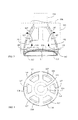
- FIG. 3 is a schematic structural view illustrating an electric luminous body being installed at the center of the end surface of a light projection side of the heat dissipater with axial and radial air apertures (101), and a radial air inlet port (108) being formed near the outer periphery of the light projection side, according to one embodiment of the present invention;
- FIG. 4 is atop view of FIG. 3 ;
- FIG. 3 and FIG. 4 it mainly consists of:
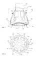
- FIG. 5 is a schematic structural view illustrating the electric luminous body being installed at the center of the end surface of the light projection side of the heat dissipater with axial and radial air apertures (101), and the light projection side being formed with an air inlet port annularly arranged near the periphery of axial end surface (110), according to one embodiment of the present invention;
- FIG. 6 is a top view of FIG. 5 ;
- FIG. 5 and FIG. 6 it mainly consists of:
- the hot airflow in the heat dissipater with axial and radial air aperture (101) generating a hot ascent/cold descent effect for introducing airflow from one or more than one air inlet ports annularly arranged near the periphery of axial end surface (110) at the light projection side (103) to pass the axial hole configured by the axial tubular flowpath (102) then be discharged from the radial air outlet hole (107) formed near the connection side (104) of the heat dissipater with axial and radial air aperture (101), thereby discharging thermal energy in the axial tubular flowpath (102) to the exterior;
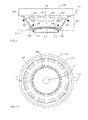
- FIG. 7 is a schematic structural view illustrating the electric luminous body downwardly projecting light and being annularly installed at the light projection side of the heat dissipater with axial and radial air apertures (101), and being formed with a central axial air inlet port (109), according to one embodiment of the present invention
- FIG. 8 is a top view of FIG. 7 ;
- FIG. 7 and FIG. 8 it mainly consists of:
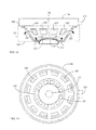
- FIG. 9 is a schematic structural view illustrating the electric luminous body downwardly projecting light in a multiple circular manner and being annularly installed at the light projection side of the heat dissipater with axial and radial air apertures (101), and being formed with an air inlet port annularly arranged near the periphery of axial end surface (110) and formed with a central axial air inlet port (109) at the periphery of the light projection side or between the electric luminous body downwardly projecting light in a multiple circular manner and annularly installed, according to one embodiment of the present invention;
- FIG. 10 is a bottom view of FIG. 9 ;
- FIG. 9 and FIG. 10 it mainly consists of:
- the air flowing formed through the hot airflow in the heat dissipater with axial and radial air aperture (101) generating a hot ascent/cold descent effect for introducing airflow from the central axial air inlet port (109) and the air inlet port annularly arranged near the periphery of axial end surface (110) of the light projection side (103) to pass the axial hole structured by the axial tubular flowpath (102) then be discharged from the radial air outlet hole (107) formed near the connection side (104) of the heat dissipater with axial and radial air aperture (101), thereby discharging thermal energy in the axial tubular flowpath (102) to the exterior;
- FIG. 11 is a schematic structural view illustrating the embodiment disclosed in FIG.3 being applied in a heat dissipater with axial and radial air aperture (101) having the top being installed with a radially-fixed and electric conductive interface (115) and installed with a top cover member (116), according to one embodiment of the present invention;
- FIG. 12 is a bottom view of FIG. 11 ;
- the radially-fixed and electric-conductive interface (115) is used for replacing the axially-fixed and electric-conductive interface (114), and a top cover member (116) is further installed, all the other components are the same as what is shown in FIG. 3 ;
- FIG. 13 is a schematic structural view illustrating the embodiment disclosed in FIG. 5 being applied in a heat dissipater with axial and radial air aperture (101) having the top being installed with a radially-fixed and electric conductive interface (115) and installed with a top cover member (116), according to one embodiment of the present invention;
- FIG. 14 is a bottom view of FIG. 13 ;
- the radially-fixed and electric-conductive interface (115) is used for replacing the axially-fixed and electric-conductive interface (114), and a top cover member (116) is further installed, all the other components are the same as what is shown in FIG. 5 ;
- FIG. 15 is a schematic structural view illustrating the embodiment disclosed in FIG. 7 being applied in a heat dissipater with axial and radial air aperture (101) having the top being installed with a radially-fixed and electric conductive interface (115) and installed with a top cover member (116), according to one embodiment of the present invention;
- FIG. 16 is a bottom view of FIG. 15 ;
- the radially-fixed and electric-conductive interface (115) is used for replacing the axially-fixed and electric-conductive interface (114), and a top cover member (116) is further installed, all the other components are the same as what is shown in FIG. 7 ;
- FIG. 17 is a schematic structural view illustrating the embodiment disclosed in FIG. 9 being applied in a heat dissipater with axial and radial air aperture (101) having the top being installed with a radially-fixed and electric conductive interface (115) and installed with a top cover member (116), according to one embodiment of the present invention;
- FIG. 18 is a bottom view of FIG. 17 ;
- the radially-fixed and electric-conductive interface (115) is used for replacing the axially-fixed and electric-conductive interface (114), and a top cover member (116) is further installed, all the other components are the same as what is shown in FIG. 9 ;
- air inlet ports can be installed at plural locations, wherein:
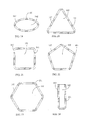
- the shape of the axial tubular flowpath (102) is not limited to be formed in the round shape, which can be further included with an oval tubular flowpath, triangle tubular flowpath, rectangular tubular flowpath, pentagonal tubular flowpath, hexangular tubular flowpath, polygonal tubular flowpath having more than six angles, U-shaped tubular flowpath, singular-slot hole tubular flowpath with dual open ends, or multiple-slot hole tubular flowpath with dual open ends; or can be shaped to a cross section having plural angles or geometric shapes, etc., illustrated with the following embodiment:
- FIG. 19 is a schematic view illustrating the axial A-A cross section of the axial tubular flowpath (102) shown in FIG. 1 being formed as an oval hole, according to one embodiment of the present invention.
- the main configuration is that the heat dissipater with axial and radial air aperture (101) is made of a material having good thermal conductivity, and between the radial air outlet hole near the connection side (104) and the air inlet port near the light projection side (103), the axial tubular flowpath (102) is served as a communicated tubular flowpath, wherein the A-A cross section of the tubular flowpath is in an oval shape.
- FIG. 20 is a schematic view illustrating the axial A-A cross section of the axial tubular flowpath (102) shown in FIG. 1 being formed as a triangular hole, according to one embodiment of the present invention
- the main configuration is that the heat dissipater with axial and radial air aperture (101) is made of a material having good thermal conductivity, and between the radial air outlet hole near the connection side (104) and the air inlet port near the light projection side (103), the axial tubular flowpath (102) is served as a communicated tubular flowpath, wherein the A-A cross section of the tubular flowpath is in a triangular or triangular-like shape.
- FIG. 21 is a schematic view illustrating the axial A-A cross section of the axial tubular flowpath (102) shown in FIG. 1 being formed as a rectangular hole, according to one embodiment of the present invention
- the main configuration is that the heat dissipater with axial and radial air aperture (101) is made of a material having good thermal conductivity, and between the radial air outlet hole near the connection side (104) and the air inlet port near the light projection side (103), the axial tubular flowpath (102) is served as a communicated tubular flowpath, wherein the A-A cross section of the tubular flowpath is in a rectangular or rectangular-like shape.
- FIG. 22 is a schematic view illustrating the axial A-A cross section of the axial tubular flowpath (102) shown in FIG. 1 being formed as a pentagonal hole, according to one embodiment of the present invention
- the main configuration is that the heat dissipater with axial and radial air aperture (101) is made of a material having good thermal conductivity, and between the radial air outlet hole near the connection side (104) and the air inlet port near the light projection side (103), the axial tubular flowpath (102) is served as a communicated tubular flowpath, wherein the A-A cross section of the tubular flowpath is in a pentagonal or pentagonal-like shape.
- FIG. 23 is a schematic view illustrating the axial A-A cross section of the axial tubular flowpath (102) shown in FIG. 1 being formed as a hexagonal hole, according to one embodiment of the present invention
- the main configuration is that the heat dissipater with axial and radial air aperture (101) is made of a material having good thermal conductivity, and between the radial air outlet hole near the connection side (104) and the air inlet port near the light projection side (103), the axial tubular flowpath (102) is served as a communicated tubular flowpath, wherein the A-A cross section of the tubular flowpath is in a hexagonal or hexagonal-like shape.
- FIG. 24 is a schematic view illustrating the axial A-A cross section of the axial tubular flowpath (102) shown in FIG. 1 being formed as a U-shaped hole, according to one embodiment of the present invention
- the main configuration is that the heat dissipater with axial and radial air aperture (101) is made of a material having good thermal conductivity, and between the radial air outlet hole near the connection side (104) and the air inlet port near the light projection side (103), the axial tubular flowpath (102) is served as a communicated tubular flowpath, wherein the A-A cross section of the tubular flowpath is in a U shape with single sealed side.
- FIG. 25 is a schematic view illustrating the axial A-A cross section of the axial tubular flowpath (102) shown in FIG. 1 being formed as a singular-slot hole with dual open ends, according to one embodiment of the present invention
- the main configuration is that the heat dissipater with axial and radial air aperture (101) is made of a material having good thermal conductivity, and between the radial air outlet hole near the connection side (104) and the air inlet port near the light projection side (103), the axial tubular flowpath (102) is served as a communicated tubular flowpath, wherein the A-A cross section of the tubular flowpath is formed as a singular-slot hole with dual open ends.
- FIG. 26 is a schematic view illustrating the axial A-A cross section of the axial tubular flowpath (102) shown in FIG. 1 being formed as a multiple-slot hole with dual open ends, according to one embodiment of the present invention
- the main configuration is that the heat dissipater with axial and radial air aperture (101) is made of a material having good thermal conductivity, and between the radial air outlet hole near the connection side (104) and the air inlet port near the light projection side (103), the axial tubular flowpath (102) is served as a communicated tubular flowpath, wherein the A-A cross section of the tubular flowpath is in formed as two or more than two slot hole with dual open ends.
- both or at least one of the interior and the exterior of the axial cross section of the axial tubular flowpath (102) can be provided with a heat dissipation fin structure (200) for increasing the heat dissipation effect;
- FIG. 27 is a schematic view illustrating the axial B-B cross section of the axial tubular flowpath (102) shown in FIG. 1 being formed as a heat dissipation fin structure (200), according to one embodiment of the present invention
- the main configuration is that the heat dissipater with axial and radial air aperture (101) is made of a material having good thermal conductivity, and between the radial air outlet hole near the connection side (104) and the air inlet port near the light projection side (103), the axial tubular flowpath (102) is served as a communicated tubular flowpath, wherein the B-B cross section of the tubular flowpath is formed with the heat dissipation fin structure (200).
- the heat dissipater with axial and radial air aperture (101) can be further formed as a porous or net-shaped structure which is made of a thermal conductive material, and the holes of the porous structure and the net holes of the net-shaped structure can be used for replacing the radial air outlet hole (107) and the radial air inlet port (108); and the light projection side (103) is formed with a block-shaped heat conductive structure allowing the electric luminous body to be installed thereon;
- FIG. 28 is a schematic view showing the heat dissipater with axial and radial air aperture (101) being formed as a porous structure, according to one embodiment of the present invention
- the heat dissipater with axial and radial air aperture (101) can be further formed as a porous structure made of a thermal conductive material, and the holes of the porous structure can be used for replacing the radial air outlet hole (107) and the radial air inlet port (108); and the light projection side (103) is formed with a block-shaped heat conductive structure allowing the electric luminous body to be installed thereon;
- FIG. 29 is a schematic view showing the heat dissipater with axial and radial air aperture (101) being formed as a net-shaped structure, according to one embodiment of the present invention.
- the heat dissipater with axial and radial air aperture (101) can be further formed as a net-shaped structure made of a thermal conductive material, and the net holes of the net-shaped structure can be used for replacing the radial air outlet hole (107) and the radial air inlet port (108); and the light projection side (103) is formed with a block-shaped heat conductive structure allowing the electric luminous body to be installed thereon.
- the inner top of the heat dissipater with axial and radial air apertures (101) is formed with a flow guide conical member (301) at the axial direction facing the light projection side (103); or formed with a flow guide conical member (302) along the axial direction facing the light projection side (103) of the heat dissipater with axial and radial air apertures (101) at the side of the axially-fixed and electric-conductive interface (114) for connecting to the heat dissipater with axial and radial air apertures (101);
- the directions of said flow guide conical members (301), (302) facing the light projection side (103) of the heat dissipater with axial and radial air apertures (101) are formed in a conical shape for guiding the hot-ascended airflow in the axial tubular flowpath (102) to the
- FIG. 30 is a schematic structural view illustrating the axial direction facing the light projection side (103) at the inner top of the heat dissipater with axial and radial air apertures (101) being formed with a flow guide conical member (301), according to one embodiment of the present invention
- the inner top of the heat dissipater with axial and radial air apertures (101) disclosed in each embodiment is formed with a flow guide conical member (301) at the axial direction facing the light projection side (103), wherein the direction of said flow guide conical member (301) facing the light projection side (103) of the heat dissipater with axial and radial air apertures (101) is formed in a conical shape for guiding the hot-ascended airflow in the axial tubular flowpath (102) to the radial air outlet hole (107);
- FIG. 31 is a schematic structural view illustrating that along the axial direction facing the light projection side (103) of the heat dissipater with axial and radial air apertures (101) at the side of the axially-fixed and electric-conductive interface (114) for connecting to the heat dissipater with axial and radial air apertures (101) being formed with a flow guide conical member (302), according to one embodiment of the present invention;
- the interior of the axial tubular flowpath (102) can be installed with an electric motor driven fan (400) for assisting the flowing of the hot airflow in the axial tubular flowpath (102) for increasing the heat dissipation effect;
- FIG. 32 is a schematic view illustrating an electric motor driven fan (400) being provided in the interior, according to one embodiment of the present invention.
- the airflow in the axial tubular flowpath (102) not only can be driven by the hot ascent/cool descent effect, but the electric motor driven fan (400) can also be further installed in the axial tubular flowpath (102) for assisting the flowing of the hot airflow in the axial tubular flowpath (102), and thereby increasing the heat dissipation effect.
Landscapes
- Engineering & Computer Science (AREA)
- General Engineering & Computer Science (AREA)
- Physics & Mathematics (AREA)
- Microelectronics & Electronic Packaging (AREA)
- Optics & Photonics (AREA)
- Geometry (AREA)
- Arrangement Of Elements, Cooling, Sealing, Or The Like Of Lighting Devices (AREA)
- Non-Portable Lighting Devices Or Systems Thereof (AREA)
- Cooling Or The Like Of Electrical Apparatus (AREA)
- Led Device Packages (AREA)
- Orthopedics, Nursing, And Contraception (AREA)
Applications Claiming Priority (3)
| Application Number | Priority Date | Filing Date | Title |
|---|---|---|---|
| US13/345,848 US8931925B2 (en) | 2012-01-09 | 2012-01-09 | LED heat dissipation device having axial and radial convection holes |
| US13/354,401 US9500356B2 (en) | 2012-01-09 | 2012-01-20 | Heat dissipater with axial and radial air aperture and application device thereof |
| EP13150434.2A EP2623859B1 (de) | 2012-01-09 | 2013-01-07 | Elektrischer Leuchtkörper mit Wärmeableiter mit axialer und radialer Luftöffnung |
Related Parent Applications (2)
| Application Number | Title | Priority Date | Filing Date |
|---|---|---|---|
| EP13150434.2A Division-Into EP2623859B1 (de) | 2012-01-09 | 2013-01-07 | Elektrischer Leuchtkörper mit Wärmeableiter mit axialer und radialer Luftöffnung |
| EP13150434.2A Division EP2623859B1 (de) | 2012-01-09 | 2013-01-07 | Elektrischer Leuchtkörper mit Wärmeableiter mit axialer und radialer Luftöffnung |
Publications (3)
| Publication Number | Publication Date |
|---|---|
| EP2837882A2 true EP2837882A2 (de) | 2015-02-18 |
| EP2837882A3 EP2837882A3 (de) | 2015-10-21 |
| EP2837882B1 EP2837882B1 (de) | 2019-06-12 |
Family
ID=47721974
Family Applications (2)
| Application Number | Title | Priority Date | Filing Date |
|---|---|---|---|
| EP13150434.2A Active EP2623859B1 (de) | 2012-01-09 | 2013-01-07 | Elektrischer Leuchtkörper mit Wärmeableiter mit axialer und radialer Luftöffnung |
| EP14185798.7A Active EP2837882B1 (de) | 2012-01-09 | 2013-01-07 | Elektrischer Leuchtkörper mit Wärmeableiter mit axialer und radialer Luftöffnung |
Family Applications Before (1)
| Application Number | Title | Priority Date | Filing Date |
|---|---|---|---|
| EP13150434.2A Active EP2623859B1 (de) | 2012-01-09 | 2013-01-07 | Elektrischer Leuchtkörper mit Wärmeableiter mit axialer und radialer Luftöffnung |
Country Status (13)
| Country | Link |
|---|---|
| US (1) | US9500356B2 (de) |
| EP (2) | EP2623859B1 (de) |
| JP (1) | JP6266884B2 (de) |
| KR (1) | KR102096110B1 (de) |
| CN (2) | CN103196047B (de) |
| AU (2) | AU2013200087B2 (de) |
| BR (2) | BR122020023285B1 (de) |
| CA (1) | CA2800579C (de) |
| ES (2) | ES2528912T3 (de) |
| IL (1) | IL224133A (de) |
| MX (1) | MX2013000328A (de) |
| SG (1) | SG192345A1 (de) |
| TW (2) | TWM462337U (de) |
Families Citing this family (24)
| Publication number | Priority date | Publication date | Assignee | Title |
|---|---|---|---|---|
| US20130176723A1 (en) * | 2011-10-06 | 2013-07-11 | Intematix Corporation | Solid-state lamps with improved radial emission and thermal performance |
| US9500356B2 (en) * | 2012-01-09 | 2016-11-22 | Tai-Her Yang | Heat dissipater with axial and radial air aperture and application device thereof |
| WO2014030085A1 (en) * | 2012-08-23 | 2014-02-27 | Koninklijke Philips N.V. | Lighting device with a led and an improved reflective collimator |
| EP2725295B1 (de) * | 2012-10-26 | 2017-11-08 | LG Electronics Inc. | Beleuchtungsvorrichtung |
| KR102252555B1 (ko) * | 2013-08-09 | 2021-05-17 | 양태허 | 측면 외부 확산 방열 및 분로 열전도 구조를 구비한 방열장치 |
| WO2015027407A1 (zh) * | 2013-08-28 | 2015-03-05 | Chen Hui Chiang | 发光二极管灯具 |
| CN104565880B (zh) * | 2013-10-11 | 2017-01-04 | 绿色再生能科技股份有限公司 | 具有压差散热装置的光源 |
| CN104728628B (zh) * | 2013-12-24 | 2016-09-28 | 四川新力光源股份有限公司 | 一种对流散热式led模组 |
| KR101580789B1 (ko) * | 2014-04-14 | 2015-12-29 | 엘지전자 주식회사 | 조명기기 |
| CN104344265B (zh) * | 2014-11-28 | 2017-03-29 | 浙江晶日照明科技有限公司 | 一种被动式风扇结构灯具 |
| US9420644B1 (en) | 2015-03-31 | 2016-08-16 | Frank Shum | LED lighting |
| CN106641777A (zh) * | 2016-10-25 | 2017-05-10 | 西安交通大学 | 一种利用灯罩和灯体表面联合散热的led球泡灯 |
| CN109323147A (zh) * | 2017-07-26 | 2019-02-12 | 慈溪飞诺斯电子科技有限公司 | 一种均匀照度的高寿命led照明光源 |
| JP7133922B2 (ja) * | 2017-12-27 | 2022-09-09 | 株式会社Kelk | 熱電発電装置 |
| US10415787B2 (en) * | 2018-01-11 | 2019-09-17 | Osram Sylvania Inc. | Vehicle LED lamp having recirculating air channels |
| CN108150982A (zh) * | 2018-01-25 | 2018-06-12 | 广东凯晟照明科技有限公司 | 灯具用高效散热器 |
| WO2019144891A1 (zh) * | 2018-01-25 | 2019-08-01 | 广东凯晟照明科技有限公司 | 高效散热型灯具及其散热器 |
| CN108167672A (zh) * | 2018-01-25 | 2018-06-15 | 广东凯晟照明科技有限公司 | 高效散热型灯具 |
| TWI677272B (zh) * | 2018-05-09 | 2019-11-11 | 胡文松 | 戶外電子設備的阻熱、散熱與防水氣、防塵結構 |
| JP7110941B2 (ja) * | 2018-11-26 | 2022-08-02 | セイコーエプソン株式会社 | 媒体加熱装置及び印刷装置 |
| KR102265147B1 (ko) | 2019-11-22 | 2021-06-15 | 재경전광산업 주식회사 | 다수의 열전구를 갖는 전열장치 |
| KR102834848B1 (ko) | 2019-11-28 | 2025-07-15 | 주식회사 엘지에너지솔루션 | 배터리 모듈, 이를 포함하는 배터리 팩 및 자동차 |
| US12092399B2 (en) * | 2020-07-14 | 2024-09-17 | Raytheon Company | Chimney cooler design for rugged maximum free convection heat transfer with minimum footprint |
| CN113719766B (zh) * | 2021-09-10 | 2024-08-27 | 广州财盟科技有限公司 | 一种便于散热的led灯珠 |
Family Cites Families (26)
| Publication number | Priority date | Publication date | Assignee | Title |
|---|---|---|---|---|
| US4503360A (en) * | 1982-07-26 | 1985-03-05 | North American Philips Lighting Corporation | Compact fluorescent lamp unit having segregated air-cooling means |
| US6793374B2 (en) * | 1998-09-17 | 2004-09-21 | Simon H. A. Begemann | LED lamp |
| US7144140B2 (en) * | 2005-02-25 | 2006-12-05 | Tsung-Ting Sun | Heat dissipating apparatus for lighting utility |
| US20060290891A1 (en) * | 2005-06-23 | 2006-12-28 | Augux Co., Ltd. | Device for cooling light emitting diode projector |
| US20070279862A1 (en) * | 2006-06-06 | 2007-12-06 | Jia-Hao Li | Heat-Dissipating Structure For Lamp |
| US7663229B2 (en) * | 2006-07-12 | 2010-02-16 | Hong Kong Applied Science And Technology Research Institute Co., Ltd. | Lighting device |
| US20080212333A1 (en) * | 2007-03-01 | 2008-09-04 | Bor-Jang Chen | Heat radiating device for lamp |
| JP4832343B2 (ja) * | 2007-03-14 | 2011-12-07 | 京セラ株式会社 | 発光装置 |
| DE102007040444B8 (de) * | 2007-08-28 | 2013-10-17 | Osram Gmbh | LED-Lampe |
| TW200946826A (en) * | 2008-05-02 | 2009-11-16 | Foxconn Tech Co Ltd | Illuminating apparatus and light engine thereof |
| US7575346B1 (en) * | 2008-07-22 | 2009-08-18 | Sunonwealth Electric Machine Industry Co., Ltd. | Lamp |
| JP2010086713A (ja) * | 2008-09-30 | 2010-04-15 | Toshiba Lighting & Technology Corp | 電球形ランプ |
| US8143769B2 (en) * | 2008-09-08 | 2012-03-27 | Intematix Corporation | Light emitting diode (LED) lighting device |
| TWM353319U (en) * | 2008-09-17 | 2009-03-21 | Essiso Technology Co Ltd | Light emitting module and light emitting device |
| US20100187963A1 (en) * | 2009-01-28 | 2010-07-29 | Guy Vaccaro | Heat Sink for Passive Cooling of a Lamp |
| CN101865369B (zh) * | 2009-04-16 | 2014-04-30 | 富准精密工业(深圳)有限公司 | 发光二极管灯具 |
| CN201539776U (zh) * | 2009-06-12 | 2010-08-04 | 东莞市兆明光电科技有限公司 | 一种led路灯 |
| TW201104156A (en) * | 2009-07-28 | 2011-02-01 | Young Dong Tech Co Ltd | Light emitting diode lighting device |
| US20110110095A1 (en) * | 2009-10-09 | 2011-05-12 | Intematix Corporation | Solid-state lamps with passive cooling |
| US8525395B2 (en) * | 2010-02-05 | 2013-09-03 | Litetronics International, Inc. | Multi-component LED lamp |
| KR20110101789A (ko) * | 2010-03-09 | 2011-09-16 | 주식회사 솔라코 컴퍼니 | 에어 파이프를 갖는 조명 커버 및 이를 이용한 엘이디 조명장치 |
| CN201706242U (zh) * | 2010-03-14 | 2011-01-12 | 林金城 | 一种led灯泡 |
| TWM412318U (en) * | 2010-04-30 | 2011-09-21 | Uhao Lighting Co Ltd | The lighting features |
| US8272765B2 (en) * | 2010-06-21 | 2012-09-25 | Light Emitting Design, Inc. | Heat sink system |
| CN201779479U (zh) * | 2010-07-01 | 2011-03-30 | 黄景温 | 一种led照明灯泡 |
| US9500356B2 (en) * | 2012-01-09 | 2016-11-22 | Tai-Her Yang | Heat dissipater with axial and radial air aperture and application device thereof |
-
2012
- 2012-01-20 US US13/354,401 patent/US9500356B2/en active Active
-
2013
- 2013-01-03 SG SG2013000344A patent/SG192345A1/en unknown
- 2013-01-07 ES ES13150434.2T patent/ES2528912T3/es active Active
- 2013-01-07 ES ES14185798T patent/ES2749114T3/es active Active
- 2013-01-07 TW TW102200312U patent/TWM462337U/zh not_active IP Right Cessation
- 2013-01-07 CN CN201310004909.XA patent/CN103196047B/zh active Active
- 2013-01-07 EP EP13150434.2A patent/EP2623859B1/de active Active
- 2013-01-07 EP EP14185798.7A patent/EP2837882B1/de active Active
- 2013-01-07 TW TW102100490A patent/TWI611142B/zh active
- 2013-01-07 CA CA2800579A patent/CA2800579C/en active Active
- 2013-01-07 CN CN2013200065810U patent/CN203082618U/zh not_active Expired - Fee Related
- 2013-01-08 KR KR1020130002067A patent/KR102096110B1/ko active Active
- 2013-01-08 AU AU2013200087A patent/AU2013200087B2/en not_active Ceased
- 2013-01-08 BR BR122020023285-4A patent/BR122020023285B1/pt active IP Right Grant
- 2013-01-08 BR BR102013000518-5A patent/BR102013000518B1/pt active IP Right Grant
- 2013-01-08 IL IL224133A patent/IL224133A/en active IP Right Grant
- 2013-01-09 MX MX2013000328A patent/MX2013000328A/es active IP Right Grant
- 2013-01-09 JP JP2013001801A patent/JP6266884B2/ja active Active
-
2016
- 2016-07-14 AU AU2016204938A patent/AU2016204938B2/en not_active Ceased
Non-Patent Citations (1)
| Title |
|---|
| None |
Also Published As
| Publication number | Publication date |
|---|---|
| BR102013000518B1 (pt) | 2021-01-19 |
| EP2623859B1 (de) | 2014-11-05 |
| US20130175915A1 (en) | 2013-07-11 |
| BR102013000518A2 (pt) | 2015-08-11 |
| CN203082618U (zh) | 2013-07-24 |
| ES2528912T3 (es) | 2015-02-13 |
| AU2013200087B2 (en) | 2016-04-14 |
| ES2749114T3 (es) | 2020-03-19 |
| CN103196047A (zh) | 2013-07-10 |
| JP2013145746A (ja) | 2013-07-25 |
| AU2016204938A1 (en) | 2016-08-04 |
| US9500356B2 (en) | 2016-11-22 |
| JP6266884B2 (ja) | 2018-01-24 |
| EP2837882B1 (de) | 2019-06-12 |
| TWM462337U (zh) | 2013-09-21 |
| CA2800579A1 (en) | 2013-07-09 |
| KR102096110B1 (ko) | 2020-04-02 |
| CN103196047B (zh) | 2017-07-07 |
| BR122020023285B1 (pt) | 2021-05-11 |
| EP2837882A3 (de) | 2015-10-21 |
| MX2013000328A (es) | 2014-07-16 |
| EP2623859A1 (de) | 2013-08-07 |
| KR20130081669A (ko) | 2013-07-17 |
| TW201339492A (zh) | 2013-10-01 |
| AU2016204938B2 (en) | 2018-03-29 |
| IL224133A (en) | 2016-10-31 |
| SG192345A1 (en) | 2013-08-30 |
| TWI611142B (zh) | 2018-01-11 |
| AU2013200087A1 (en) | 2013-07-25 |
| CA2800579C (en) | 2021-01-26 |
Similar Documents
| Publication | Publication Date | Title |
|---|---|---|
| EP2837882B1 (de) | Elektrischer Leuchtkörper mit Wärmeableiter mit axialer und radialer Luftöffnung | |
| US8931925B2 (en) | LED heat dissipation device having axial and radial convection holes | |
| EP2997305B1 (de) | Beleuchtungsvorrichtung und leuchte | |
| CN104272022A (zh) | 具有散热器和主动冷却装置的灯 | |
| TWI582341B (zh) | 應用於電能發光體之具導熱肋條及導流孔之杯形散熱體 | |
| WO2015129419A1 (ja) | Ledランプ | |
| US20130163247A1 (en) | Lamp base and lamp having the same | |
| US10928056B2 (en) | Lighting device | |
| CN101598315B (zh) | 照明装置及其散热结构 | |
| EP3462077A1 (de) | Beleuchtungsvorrichtung | |
| JP3183632U (ja) | 放熱装置およびそれを用いる発光装置 | |
| KR101764399B1 (ko) | 방열이 우수한 엘이디램프 |
Legal Events
| Date | Code | Title | Description |
|---|---|---|---|
| 17P | Request for examination filed |
Effective date: 20140922 |
|
| AC | Divisional application: reference to earlier application |
Ref document number: 2623859 Country of ref document: EP Kind code of ref document: P |
|
| AK | Designated contracting states |
Kind code of ref document: A2 Designated state(s): AL AT BE BG CH CY CZ DE DK EE ES FI FR GB GR HR HU IE IS IT LI LT LU LV MC MK MT NL NO PL PT RO RS SE SI SK SM TR |
|
| PUAI | Public reference made under article 153(3) epc to a published international application that has entered the european phase |
Free format text: ORIGINAL CODE: 0009012 |
|
| PUAL | Search report despatched |
Free format text: ORIGINAL CODE: 0009013 |
|
| AK | Designated contracting states |
Kind code of ref document: A3 Designated state(s): AL AT BE BG CH CY CZ DE DK EE ES FI FR GB GR HR HU IE IS IT LI LT LU LV MC MK MT NL NO PL PT RO RS SE SI SK SM TR |
|
| RIC1 | Information provided on ipc code assigned before grant |
Ipc: F21V 29/00 20150101AFI20150911BHEP Ipc: F21Y 101/02 20060101ALI20150911BHEP |
|
| R17P | Request for examination filed (corrected) |
Effective date: 20160421 |
|
| RBV | Designated contracting states (corrected) |
Designated state(s): AL AT BE BG CH CY CZ DE DK EE ES FI FR GB GR HR HU IE IS IT LI LT LU LV MC MK MT NL NO PL PT RO RS SE SI SK SM TR |
|
| RIC1 | Information provided on ipc code assigned before grant |
Ipc: F21Y 115/10 20160101ALN20181002BHEP Ipc: F21V 29/83 20150101ALI20181002BHEP Ipc: F21Y 103/33 20160101ALN20181002BHEP Ipc: F21K 9/00 20160101AFI20181002BHEP Ipc: F21V 29/67 20150101ALI20181002BHEP |
|
| RIC1 | Information provided on ipc code assigned before grant |
Ipc: F21K 9/00 20150218AFI20181005BHEP Ipc: F21Y 103/33 20150218ALN20181005BHEP Ipc: F21V 29/83 20150101ALI20181005BHEP Ipc: F21Y 115/10 20150218ALN20181005BHEP Ipc: F21V 29/67 20150101ALI20181005BHEP |
|
| REG | Reference to a national code |
Ref country code: DE Ref legal event code: R079 Ref document number: 602013056676 Country of ref document: DE Free format text: PREVIOUS MAIN CLASS: F21V0029000000 Ipc: F21K0009000000 |
|
| GRAP | Despatch of communication of intention to grant a patent |
Free format text: ORIGINAL CODE: EPIDOSNIGR1 |
|
| STAA | Information on the status of an ep patent application or granted ep patent |
Free format text: STATUS: GRANT OF PATENT IS INTENDED |
|
| RIC1 | Information provided on ipc code assigned before grant |
Ipc: F21V 29/67 20150101ALI20181005BHEP Ipc: F21Y 115/10 20160101ALN20181005BHEP Ipc: F21V 29/83 20150101ALI20181005BHEP Ipc: F21K 9/00 20160101AFI20181005BHEP Ipc: F21Y 103/33 20160101ALN20181005BHEP |
|
| RIC1 | Information provided on ipc code assigned before grant |
Ipc: F21V 29/83 20150101ALI20181203BHEP Ipc: F21Y 103/33 20160101ALN20181203BHEP Ipc: F21Y 115/10 20160101ALN20181203BHEP Ipc: F21K 9/00 20160101AFI20181203BHEP Ipc: F21V 29/67 20150101ALI20181203BHEP |
|
| INTG | Intention to grant announced |
Effective date: 20181221 |
|
| RIC1 | Information provided on ipc code assigned before grant |
Ipc: F21V 29/67 20150101ALI20181203BHEP Ipc: F21Y 103/33 20160101ALN20181203BHEP Ipc: F21Y 115/10 20160101ALN20181203BHEP Ipc: F21K 9/00 20160101AFI20181203BHEP Ipc: F21V 29/83 20150101ALI20181203BHEP |
|
| GRAS | Grant fee paid |
Free format text: ORIGINAL CODE: EPIDOSNIGR3 |
|
| GRAA | (expected) grant |
Free format text: ORIGINAL CODE: 0009210 |
|
| STAA | Information on the status of an ep patent application or granted ep patent |
Free format text: STATUS: THE PATENT HAS BEEN GRANTED |
|
| AC | Divisional application: reference to earlier application |
Ref document number: 2623859 Country of ref document: EP Kind code of ref document: P |
|
| AK | Designated contracting states |
Kind code of ref document: B1 Designated state(s): AL AT BE BG CH CY CZ DE DK EE ES FI FR GB GR HR HU IE IS IT LI LT LU LV MC MK MT NL NO PL PT RO RS SE SI SK SM TR |
|
| REG | Reference to a national code |
Ref country code: GB Ref legal event code: FG4D |
|
| REG | Reference to a national code |
Ref country code: CH Ref legal event code: EP |
|
| REG | Reference to a national code |
Ref country code: AT Ref legal event code: REF Ref document number: 1143015 Country of ref document: AT Kind code of ref document: T Effective date: 20190615 |
|
| REG | Reference to a national code |
Ref country code: DE Ref legal event code: R096 Ref document number: 602013056676 Country of ref document: DE |
|
| REG | Reference to a national code |
Ref country code: IE Ref legal event code: FG4D |
|
| REG | Reference to a national code |
Ref country code: NL Ref legal event code: FP |
|
| REG | Reference to a national code |
Ref country code: LT Ref legal event code: MG4D |
|
| PG25 | Lapsed in a contracting state [announced via postgrant information from national office to epo] |
Ref country code: LT Free format text: LAPSE BECAUSE OF FAILURE TO SUBMIT A TRANSLATION OF THE DESCRIPTION OR TO PAY THE FEE WITHIN THE PRESCRIBED TIME-LIMIT Effective date: 20190612 Ref country code: NO Free format text: LAPSE BECAUSE OF FAILURE TO SUBMIT A TRANSLATION OF THE DESCRIPTION OR TO PAY THE FEE WITHIN THE PRESCRIBED TIME-LIMIT Effective date: 20190912 Ref country code: FI Free format text: LAPSE BECAUSE OF FAILURE TO SUBMIT A TRANSLATION OF THE DESCRIPTION OR TO PAY THE FEE WITHIN THE PRESCRIBED TIME-LIMIT Effective date: 20190612 Ref country code: AL Free format text: LAPSE BECAUSE OF FAILURE TO SUBMIT A TRANSLATION OF THE DESCRIPTION OR TO PAY THE FEE WITHIN THE PRESCRIBED TIME-LIMIT Effective date: 20190612 Ref country code: SE Free format text: LAPSE BECAUSE OF FAILURE TO SUBMIT A TRANSLATION OF THE DESCRIPTION OR TO PAY THE FEE WITHIN THE PRESCRIBED TIME-LIMIT Effective date: 20190612 Ref country code: HR Free format text: LAPSE BECAUSE OF FAILURE TO SUBMIT A TRANSLATION OF THE DESCRIPTION OR TO PAY THE FEE WITHIN THE PRESCRIBED TIME-LIMIT Effective date: 20190612 |
|
| PG25 | Lapsed in a contracting state [announced via postgrant information from national office to epo] |
Ref country code: BG Free format text: LAPSE BECAUSE OF FAILURE TO SUBMIT A TRANSLATION OF THE DESCRIPTION OR TO PAY THE FEE WITHIN THE PRESCRIBED TIME-LIMIT Effective date: 20190912 Ref country code: GR Free format text: LAPSE BECAUSE OF FAILURE TO SUBMIT A TRANSLATION OF THE DESCRIPTION OR TO PAY THE FEE WITHIN THE PRESCRIBED TIME-LIMIT Effective date: 20190913 Ref country code: LV Free format text: LAPSE BECAUSE OF FAILURE TO SUBMIT A TRANSLATION OF THE DESCRIPTION OR TO PAY THE FEE WITHIN THE PRESCRIBED TIME-LIMIT Effective date: 20190612 Ref country code: RS Free format text: LAPSE BECAUSE OF FAILURE TO SUBMIT A TRANSLATION OF THE DESCRIPTION OR TO PAY THE FEE WITHIN THE PRESCRIBED TIME-LIMIT Effective date: 20190612 |
|
| REG | Reference to a national code |
Ref country code: AT Ref legal event code: MK05 Ref document number: 1143015 Country of ref document: AT Kind code of ref document: T Effective date: 20190612 |
|
| PG25 | Lapsed in a contracting state [announced via postgrant information from national office to epo] |
Ref country code: EE Free format text: LAPSE BECAUSE OF FAILURE TO SUBMIT A TRANSLATION OF THE DESCRIPTION OR TO PAY THE FEE WITHIN THE PRESCRIBED TIME-LIMIT Effective date: 20190612 Ref country code: AT Free format text: LAPSE BECAUSE OF FAILURE TO SUBMIT A TRANSLATION OF THE DESCRIPTION OR TO PAY THE FEE WITHIN THE PRESCRIBED TIME-LIMIT Effective date: 20190612 Ref country code: CZ Free format text: LAPSE BECAUSE OF FAILURE TO SUBMIT A TRANSLATION OF THE DESCRIPTION OR TO PAY THE FEE WITHIN THE PRESCRIBED TIME-LIMIT Effective date: 20190612 Ref country code: RO Free format text: LAPSE BECAUSE OF FAILURE TO SUBMIT A TRANSLATION OF THE DESCRIPTION OR TO PAY THE FEE WITHIN THE PRESCRIBED TIME-LIMIT Effective date: 20190612 Ref country code: PT Free format text: LAPSE BECAUSE OF FAILURE TO SUBMIT A TRANSLATION OF THE DESCRIPTION OR TO PAY THE FEE WITHIN THE PRESCRIBED TIME-LIMIT Effective date: 20191014 Ref country code: SK Free format text: LAPSE BECAUSE OF FAILURE TO SUBMIT A TRANSLATION OF THE DESCRIPTION OR TO PAY THE FEE WITHIN THE PRESCRIBED TIME-LIMIT Effective date: 20190612 |
|
| PG25 | Lapsed in a contracting state [announced via postgrant information from national office to epo] |
Ref country code: SM Free format text: LAPSE BECAUSE OF FAILURE TO SUBMIT A TRANSLATION OF THE DESCRIPTION OR TO PAY THE FEE WITHIN THE PRESCRIBED TIME-LIMIT Effective date: 20190612 Ref country code: IS Free format text: LAPSE BECAUSE OF FAILURE TO SUBMIT A TRANSLATION OF THE DESCRIPTION OR TO PAY THE FEE WITHIN THE PRESCRIBED TIME-LIMIT Effective date: 20191012 |
|
| REG | Reference to a national code |
Ref country code: DE Ref legal event code: R097 Ref document number: 602013056676 Country of ref document: DE |
|
| REG | Reference to a national code |
Ref country code: ES Ref legal event code: FG2A Ref document number: 2749114 Country of ref document: ES Kind code of ref document: T3 Effective date: 20200319 |
|
| PG25 | Lapsed in a contracting state [announced via postgrant information from national office to epo] |
Ref country code: TR Free format text: LAPSE BECAUSE OF FAILURE TO SUBMIT A TRANSLATION OF THE DESCRIPTION OR TO PAY THE FEE WITHIN THE PRESCRIBED TIME-LIMIT Effective date: 20190612 |
|
| PLBE | No opposition filed within time limit |
Free format text: ORIGINAL CODE: 0009261 |
|
| STAA | Information on the status of an ep patent application or granted ep patent |
Free format text: STATUS: NO OPPOSITION FILED WITHIN TIME LIMIT |
|
| PG25 | Lapsed in a contracting state [announced via postgrant information from national office to epo] |
Ref country code: PL Free format text: LAPSE BECAUSE OF FAILURE TO SUBMIT A TRANSLATION OF THE DESCRIPTION OR TO PAY THE FEE WITHIN THE PRESCRIBED TIME-LIMIT Effective date: 20190612 Ref country code: DK Free format text: LAPSE BECAUSE OF FAILURE TO SUBMIT A TRANSLATION OF THE DESCRIPTION OR TO PAY THE FEE WITHIN THE PRESCRIBED TIME-LIMIT Effective date: 20190612 |
|
| 26N | No opposition filed |
Effective date: 20200313 |
|
| PG25 | Lapsed in a contracting state [announced via postgrant information from national office to epo] |
Ref country code: IS Free format text: LAPSE BECAUSE OF FAILURE TO SUBMIT A TRANSLATION OF THE DESCRIPTION OR TO PAY THE FEE WITHIN THE PRESCRIBED TIME-LIMIT Effective date: 20200224 Ref country code: SI Free format text: LAPSE BECAUSE OF FAILURE TO SUBMIT A TRANSLATION OF THE DESCRIPTION OR TO PAY THE FEE WITHIN THE PRESCRIBED TIME-LIMIT Effective date: 20190612 |
|
| PG2D | Information on lapse in contracting state deleted |
Ref country code: IS |
|
| PG25 | Lapsed in a contracting state [announced via postgrant information from national office to epo] |
Ref country code: MC Free format text: LAPSE BECAUSE OF FAILURE TO SUBMIT A TRANSLATION OF THE DESCRIPTION OR TO PAY THE FEE WITHIN THE PRESCRIBED TIME-LIMIT Effective date: 20190612 |
|
| REG | Reference to a national code |
Ref country code: CH Ref legal event code: PL |
|
| REG | Reference to a national code |
Ref country code: BE Ref legal event code: MM Effective date: 20200131 |
|
| PG25 | Lapsed in a contracting state [announced via postgrant information from national office to epo] |
Ref country code: LU Free format text: LAPSE BECAUSE OF NON-PAYMENT OF DUE FEES Effective date: 20200107 |
|
| PG25 | Lapsed in a contracting state [announced via postgrant information from national office to epo] |
Ref country code: LI Free format text: LAPSE BECAUSE OF NON-PAYMENT OF DUE FEES Effective date: 20200131 Ref country code: BE Free format text: LAPSE BECAUSE OF NON-PAYMENT OF DUE FEES Effective date: 20200131 Ref country code: CH Free format text: LAPSE BECAUSE OF NON-PAYMENT OF DUE FEES Effective date: 20200131 |
|
| PG25 | Lapsed in a contracting state [announced via postgrant information from national office to epo] |
Ref country code: IE Free format text: LAPSE BECAUSE OF NON-PAYMENT OF DUE FEES Effective date: 20200107 |
|
| PG25 | Lapsed in a contracting state [announced via postgrant information from national office to epo] |
Ref country code: MT Free format text: LAPSE BECAUSE OF FAILURE TO SUBMIT A TRANSLATION OF THE DESCRIPTION OR TO PAY THE FEE WITHIN THE PRESCRIBED TIME-LIMIT Effective date: 20190612 Ref country code: CY Free format text: LAPSE BECAUSE OF FAILURE TO SUBMIT A TRANSLATION OF THE DESCRIPTION OR TO PAY THE FEE WITHIN THE PRESCRIBED TIME-LIMIT Effective date: 20190612 |
|
| PG25 | Lapsed in a contracting state [announced via postgrant information from national office to epo] |
Ref country code: MK Free format text: LAPSE BECAUSE OF FAILURE TO SUBMIT A TRANSLATION OF THE DESCRIPTION OR TO PAY THE FEE WITHIN THE PRESCRIBED TIME-LIMIT Effective date: 20190612 |
|
| PGFP | Annual fee paid to national office [announced via postgrant information from national office to epo] |
Ref country code: ES Payment date: 20250207 Year of fee payment: 13 |
|
| PGFP | Annual fee paid to national office [announced via postgrant information from national office to epo] |
Ref country code: NL Payment date: 20260130 Year of fee payment: 14 |
|
| PGFP | Annual fee paid to national office [announced via postgrant information from national office to epo] |
Ref country code: GB Payment date: 20260130 Year of fee payment: 14 |
|
| PGFP | Annual fee paid to national office [announced via postgrant information from national office to epo] |
Ref country code: DE Payment date: 20260218 Year of fee payment: 14 |
|
| PGFP | Annual fee paid to national office [announced via postgrant information from national office to epo] |
Ref country code: IT Payment date: 20260130 Year of fee payment: 14 |
|
| PGFP | Annual fee paid to national office [announced via postgrant information from national office to epo] |
Ref country code: FR Payment date: 20260130 Year of fee payment: 14 |