EP2837525A2 - Electric railcar power feeding system, power feeding device, and power storage device - Google Patents
Electric railcar power feeding system, power feeding device, and power storage device Download PDFInfo
- Publication number
- EP2837525A2 EP2837525A2 EP14180226.4A EP14180226A EP2837525A2 EP 2837525 A2 EP2837525 A2 EP 2837525A2 EP 14180226 A EP14180226 A EP 14180226A EP 2837525 A2 EP2837525 A2 EP 2837525A2
- Authority
- EP
- European Patent Office
- Prior art keywords
- power
- feeder line
- power storage
- charge
- current
- Prior art date
- Legal status (The legal status is an assumption and is not a legal conclusion. Google has not performed a legal analysis and makes no representation as to the accuracy of the status listed.)
- Withdrawn
Links
- 238000004146 energy storage Methods 0.000 claims description 2
- 230000007423 decrease Effects 0.000 description 9
- 238000006243 chemical reaction Methods 0.000 description 8
- 230000003247 decreasing effect Effects 0.000 description 6
- 238000005516 engineering process Methods 0.000 description 5
- 238000007726 management method Methods 0.000 description 5
- 238000012806 monitoring device Methods 0.000 description 5
- 230000009466 transformation Effects 0.000 description 5
- 238000001514 detection method Methods 0.000 description 4
- 238000010586 diagram Methods 0.000 description 4
- 238000000034 method Methods 0.000 description 3
- 239000003990 capacitor Substances 0.000 description 2
- 239000004020 conductor Substances 0.000 description 2
- 238000007599 discharging Methods 0.000 description 2
- HBMJWWWQQXIZIP-UHFFFAOYSA-N silicon carbide Chemical compound [Si+]#[C-] HBMJWWWQQXIZIP-UHFFFAOYSA-N 0.000 description 2
- 229910010271 silicon carbide Inorganic materials 0.000 description 2
- HBBGRARXTFLTSG-UHFFFAOYSA-N Lithium ion Chemical compound [Li+] HBBGRARXTFLTSG-UHFFFAOYSA-N 0.000 description 1
- 239000002253 acid Substances 0.000 description 1
- 230000033228 biological regulation Effects 0.000 description 1
- 230000005611 electricity Effects 0.000 description 1
- 239000000446 fuel Substances 0.000 description 1
- 238000005286 illumination Methods 0.000 description 1
- 238000009434 installation Methods 0.000 description 1
- 229910001416 lithium ion Inorganic materials 0.000 description 1
- 238000012423 maintenance Methods 0.000 description 1
- 229910052987 metal hydride Inorganic materials 0.000 description 1
- 238000012986 modification Methods 0.000 description 1
- 230000004048 modification Effects 0.000 description 1
- 230000001172 regenerating effect Effects 0.000 description 1
- 230000008929 regeneration Effects 0.000 description 1
- 238000011069 regeneration method Methods 0.000 description 1
- 238000005096 rolling process Methods 0.000 description 1
- 238000006467 substitution reaction Methods 0.000 description 1
Images


Classifications
-
- B—PERFORMING OPERATIONS; TRANSPORTING
- B60—VEHICLES IN GENERAL
- B60L—PROPULSION OF ELECTRICALLY-PROPELLED VEHICLES; SUPPLYING ELECTRIC POWER FOR AUXILIARY EQUIPMENT OF ELECTRICALLY-PROPELLED VEHICLES; ELECTRODYNAMIC BRAKE SYSTEMS FOR VEHICLES IN GENERAL; MAGNETIC SUSPENSION OR LEVITATION FOR VEHICLES; MONITORING OPERATING VARIABLES OF ELECTRICALLY-PROPELLED VEHICLES; ELECTRIC SAFETY DEVICES FOR ELECTRICALLY-PROPELLED VEHICLES
- B60L9/00—Electric propulsion with power supply external to the vehicle
- B60L9/02—Electric propulsion with power supply external to the vehicle using DC motors
- B60L9/08—Electric propulsion with power supply external to the vehicle using DC motors fed from AC supply lines
-
- B—PERFORMING OPERATIONS; TRANSPORTING
- B60—VEHICLES IN GENERAL
- B60L—PROPULSION OF ELECTRICALLY-PROPELLED VEHICLES; SUPPLYING ELECTRIC POWER FOR AUXILIARY EQUIPMENT OF ELECTRICALLY-PROPELLED VEHICLES; ELECTRODYNAMIC BRAKE SYSTEMS FOR VEHICLES IN GENERAL; MAGNETIC SUSPENSION OR LEVITATION FOR VEHICLES; MONITORING OPERATING VARIABLES OF ELECTRICALLY-PROPELLED VEHICLES; ELECTRIC SAFETY DEVICES FOR ELECTRICALLY-PROPELLED VEHICLES
- B60L3/00—Electric devices on electrically-propelled vehicles for safety purposes; Monitoring operating variables, e.g. speed, deceleration or energy consumption
- B60L3/0092—Electric devices on electrically-propelled vehicles for safety purposes; Monitoring operating variables, e.g. speed, deceleration or energy consumption with use of redundant elements for safety purposes
-
- B—PERFORMING OPERATIONS; TRANSPORTING
- B60—VEHICLES IN GENERAL
- B60M—POWER SUPPLY LINES, AND DEVICES ALONG RAILS, FOR ELECTRICALLY- PROPELLED VEHICLES
- B60M3/00—Feeding power to supply lines in contact with collector on vehicles; Arrangements for consuming regenerative power
- B60M3/06—Arrangements for consuming regenerative power
-
- B—PERFORMING OPERATIONS; TRANSPORTING
- B60—VEHICLES IN GENERAL
- B60L—PROPULSION OF ELECTRICALLY-PROPELLED VEHICLES; SUPPLYING ELECTRIC POWER FOR AUXILIARY EQUIPMENT OF ELECTRICALLY-PROPELLED VEHICLES; ELECTRODYNAMIC BRAKE SYSTEMS FOR VEHICLES IN GENERAL; MAGNETIC SUSPENSION OR LEVITATION FOR VEHICLES; MONITORING OPERATING VARIABLES OF ELECTRICALLY-PROPELLED VEHICLES; ELECTRIC SAFETY DEVICES FOR ELECTRICALLY-PROPELLED VEHICLES
- B60L2200/00—Type of vehicles
- B60L2200/26—Rail vehicles
-
- B—PERFORMING OPERATIONS; TRANSPORTING
- B60—VEHICLES IN GENERAL
- B60M—POWER SUPPLY LINES, AND DEVICES ALONG RAILS, FOR ELECTRICALLY- PROPELLED VEHICLES
- B60M3/00—Feeding power to supply lines in contact with collector on vehicles; Arrangements for consuming regenerative power
- B60M3/02—Feeding power to supply lines in contact with collector on vehicles; Arrangements for consuming regenerative power with means for maintaining voltage within a predetermined range
-
- Y—GENERAL TAGGING OF NEW TECHNOLOGICAL DEVELOPMENTS; GENERAL TAGGING OF CROSS-SECTIONAL TECHNOLOGIES SPANNING OVER SEVERAL SECTIONS OF THE IPC; TECHNICAL SUBJECTS COVERED BY FORMER USPC CROSS-REFERENCE ART COLLECTIONS [XRACs] AND DIGESTS
- Y02—TECHNOLOGIES OR APPLICATIONS FOR MITIGATION OR ADAPTATION AGAINST CLIMATE CHANGE
- Y02T—CLIMATE CHANGE MITIGATION TECHNOLOGIES RELATED TO TRANSPORTATION
- Y02T30/00—Transportation of goods or passengers via railways, e.g. energy recovery or reducing air resistance
Definitions
- Embodiments described herein relate generally to an electric railcar power feeding system, a power feeding device, and a power storage device.
- the electric railcar of the monorail or the like cannot be said to have space enough to mount the power storage device thereon. Further, mounting the power storage device being a high-energy body on the electric railcar results in an increased risk such as fire. In particular, in the transportation system such as the monorail, there also occurs a risk of parts falling after reconstruction work for mounting the power storage device.
- a power storage device of an overhead contact line direct-coupled type generally needs to have a larger number of cells in series, resulting in an increase in size of the whole power storage device and in cost. Further, in consideration of the voltage drop in the feeder line, movement of vehicle for a long distance is difficult.
- An electric railcar power feeding system in an embodiment includes a power storage device, a rectifier, and an emergency power supply.
- the power storage device is connected to a feeder line for an electric railcar.
- the rectifier converts alternating-current power of a first power system to direct-current power and supply the direct-current power for the feeder line.
- the emergency power supply supplies power of a second power system different from the first power system for the feeder line.
- an electric railcar power feeding system 10 in this embodiment is a power feeding system of a direct-current feeding type that feeds direct-current power to electric railcars 14 via a feeder line 2 of a railroad, a monorail and so on.
- the electric railcar power feeding system 10 includes a feeder control device (a power feeding device) 15, power storage devices 20, and a monitoring device 25 that collectively controls the feeder control device 15 and the power storage devices 20 as illustrated in Fig. 1 .
- the feeder control device 15 is installed, for example, every 5 km or at every station of the railroad, monorail and so on. As illustrated in Fig. 1 , the feeder control device 15 mainly includes an alternating-current circuit breaker 12, a transformer 7, a normal power supply circuit breaker 6, an emergency power supply 8(a power supply of a second power system), an emergency power supply circuit breaker 22, a rectifier 16, a direct-current circuit breaker 23 as feeding facilities.
- the alternating-current circuit breaker 12 electrically connects or disconnects an alternating-current power supply 9 being a commercial power supply and the transformer 7 to/from each other.
- the aforementioned alternating-current power supply 9 (an alternating-current power supply of a first power system) is a normal power supply of an alternating-current system for direct-current feeding.
- the transformer 7 varies the voltage of the alternating-current power supply 9.
- the normal power supply circuit breaker 6 electrically connects or disconnects the transformer 7 and the rectifier 16 to/from each other.
- the emergency power supply 8 is, for example, a gas turbine generator or a diesel generator.
- the emergency power supply 8 supplies power of the second power system different from the first power system (an alternating-current power of the alternating-current power supply 9) for the feeder line 2.
- the emergency power supply circuit breaker 22 electrically connects or disconnects the emergency power supply 8 and the rectifier 16 to/from each other.
- a transformer for voltage regulation may be separately provided at the stage subsequent to the emergency power supply 8 such that the emergency power supply 8 and the rectifier 16 are connected to each other via the separately provided transformer and the emergency power supply circuit breaker 22.
- the rectifier 16 is, for example, a diode rectifier or a PWM converter, and is an AC/DC converter that converts alternating current to direct current.
- the rectifier 16 converts the alternating-current power of the first power system (the alternating-current power of the alternating-current power supply 9) to direct-current power and supply the direct-current power for the feeder line 2.
- the direct-current circuit breaker 23 in the feeder control device 15 electrically connects or disconnects the rectifier 16 and the feeder line 2 to/from each other. Note that those instruments in the feeder control device 15 do not necessarily needs to be collectively arranged in the same device.
- the electric railcars 14 travel by receiving the direct-current power via the feeder line 2 from the feeder control device 15 side. All electric rolling stocks, which travel using electricity as a driving source such as vehicles used for the monorail and vehicles used for the railroad, correspond to the electric railcars 14.
- a return feeder 3 is a conductor through which a return current flows and, for example, a rail in the case of the conventional railroad, has such function.
- a dedicated conductor through which the return current flows is installed as the return feeder 3.
- the power storage devices 20 are arranged, for example, every 3 km in a distributed manner, and installed at a distance from the installation position of the feeder control device 15. As illustrated in Fig. 1 , Fig. 2 , the power storage device 20 is connected to the feeder line 2 for an electric railcar. Further, the power storage device 20 is connected to the return feeder 3.
- the power storage device 20 includes a power storage element 21, a converter 5, and a direct-current circuit breaker 23.
- the power storage element 21 is, for example, a storage battery such as a lithium-ion battery, a nickel-metal hydride battery, or a lead-acid battery, or an energy storage element such as an electric double layer capacitor, or a flywheel.
- the power storage device 20 performs charge and discharge according to rise and drop in feeder line voltage respectively as will be described later.
- the power storage device 20 performs discharge when the value of the feeder line voltage is equal to or less than a discharge threshold (A1 to A2) that varies according to the state of charge (SOC) of the power storage device 20 as illustrated, for example, in Fig. 3 .
- the power storage device 20 performs charge when the value of the feeder line voltage is equal to or greater than a charge threshold (B1 to B2) that varies according to the state of charge (SOC) of the power storage device 20.
- a voltage range S of the feeder line voltage in Fig. 3 indicates a voltage range where the power storage device 20 does not perform charge/discharge (a voltage range where the converter 5 is stopped for gate block).
- the power storage device 20 may be configured to stop charge/discharge when the value of current flowing through the feeder line 2 or the value of the power is greater than a discharge threshold corresponding to the value of the current or the value of the power and less than the charge threshold. Instead of this, the power storage device 20 may also be configured to stop charge/discharge when the state that the value of current flowing through the feeder line 2 or the value of the power is greater than the discharge threshold corresponding to the value of the current or the value of the power and less than the charge threshold continues for a predetermined period.
- the direct-current circuit breaker 23 in the power storage device 20 electrically connects or disconnects the converter 5 and the feeder line 2 to/from each other.
- the converter 5 sends/receive power to/from the feeder line 2 and the power storage element 21.
- the converter 5 is configured to have a function of a DC/DC converter if the power storage element 21 is, for example, a storage battery or capacitor, and to have a function of an inverter that realizes DC/AC conversion if the power storage element 21 is, for example, a flywheel.
- the monitoring device 25 acquires, for example, the voltage of the feeder line 2 and, according to an input operation by an operator based on the acquired feeder line voltage, controls the operations of the direct-current circuit breaker 23, the alternating-current circuit breaker 12, the normal power supply circuit breaker 6, the emergency power supply 8, the emergency power supply circuit breaker 22, and the direct-current circuit breaker 23 in the feeder control device 15, and the direct-current circuit breaker 23 and the converter 5 in the power storage device 20.
- the converter 5 (a charge/discharge control unit) controls the charge and the discharge of the power storage element 21 according to rise and drop in the voltage of the feeder line 2. As illustrated in Fig. 2 , the converter 5 includes a power conversion unit 5a, a current control unit 5b, a charge/discharge management table 5c, a feeder line voltage detection unit 5d, and a charge state detection unit 5e.
- the power conversion unit 5a is configured as a step-up/down chopper circuit (buck-boost Converter) or the like that gate-drives, for example, a switching element, and controls the charge/discharge operation of the power storage element 21.
- a step-up/down chopper circuit buck-boost Converter
- An example of the element to be applied to the power conversion unit 5a is, for example, a self-arc-extinguishing element such as an IGBT (Insulated Gate Bipolar Transistor), and the charge/discharge operation of the power storage element 21 is controlled by driving this kind of element in PWM (Pulse Width Modulation).
- the current control unit 5b controls the operation of the direct-current circuit breaker 23 in the power storage device 20, while the power conversion unit 5a controls the charge/discharge current (the charge current and the discharge current) that inputs/outputs from/to the feeder line 2 to/from the power storage element 21.
- the feeder line voltage detection unit 5d detects the feeder line voltage of the feeder line 2.
- the charge state detection unit 5e detects the state of charge (SOC) of the power storage element 21 as a charge rate [%].
- the charge/discharge management table 5c stores the correspondence between the feeder line voltage and the state of charge (SOC) of the power storage element 21, as charge/discharge characteristics, in order to decide the discharge threshold voltage (A1 to A2) and the charge threshold voltage (B1 to B2) according to the feeder line voltage as illustrated in Fig. 3, Fig. 4 .
- the charge/discharge management table 5c stores, for example, two kinds of charge/discharge characteristics different according to the power failure time of the alternating-current power supply 9 and the normal time when the power can be supplied from the alternating-current power supply 9.
- the current control unit 5b varies the discharge threshold voltage and the charge threshold voltage on the basis of the detected feeder line voltage, the state of charge of the power storage element 21, and the charge/discharge characteristics stored in the charge/discharge management table 5c as illustrated in Fig. 3, Fig. 4 .
- the current control unit 5b thereby adjusts the charge/discharge current of the power storage element 21 by the power conversion unit 5a.
- the power storage device 20 performs charge/discharge according to the feeder line voltage.
- the power storage device 20 performs discharge when absorbing excessive regenerative power or when the feeder line voltage decreases, to stabilize the feeder line voltage.
- the emergency power supply circuit breaker 22 in the feeder control device 15 is kept open.
- the alternating-current power supply 9 passes through the transformer 7 and is converted to direct-current power at the rectifier 16, and is then supplied to the electric railcars 14 via the feeder line 2.
- the monitoring device 25 controls the alternating-current circuit breaker 12 and the normal power supply circuit breaker 6 to open the direct-current circuit breaker 23 in the feeder control device 15.
- the direct-current circuit breakers 23 in the power storage devices 20 may be opened in cooperation with the operation of the feeder control device 15 to stop the power storage devices 20.
- the monitoring device 25 performs controls to continue the charge/discharge operation without opening the direct-current circuit breakers 23 in the power storage devices 20, thereby making it possible not to stop the electric railcars 14 but to operate the electric railcars 14, for example, to the nearest stations.
- a low-loss device such as, for example, an SiC (Silicon Carbide) power device that is a high-efficiency device is applied to the power storage device 20 so as to avoid a decrease in charge rate of the power storage element due to continuous generation of switching loss of the converter 5 and an increase in storage capacity in consideration of the decrease, thereby simplifying the facilities.
- the monitoring device 25 performs control to activate the emergency power supply 8 and turn on (close) the emergency power supply circuit breaker 22.
- the direct-current circuit breaker 23 in the feeder control device 15 is turned on (closed) to supply the direct-current power to the feeder line 2.
- the power storage device 20 is activated to turn on the direct-current circuit breaker 23 in the power storage device 20 to cause the power storage device 20 to cooperate with the feeder system.
- the power storage device 20 has characteristics of discharging when the feeder line voltage is decreased to be lower than the discharge threshold voltage as illustrated in Fig. 3 .
- the power storage device 20 gate-blocks the converter 5 when not discharging, to stop the power conversion operation by the converter 5.
- the power storage device 20 may gate-block it upon detecting the fact that a predetermined time of a predetermined output value has elapsed or may gate-block it under the condition that the state of charge (SOC) reaches within a predetermined rage.
- SOC state of charge
- the power storage device 20 has characteristics of charging when the feeder line voltage rises to be higher than the charge threshold voltage as illustrated in Fig. 3 . Further, the above-described charge threshold voltage has characteristics of decreasing as the state of charge (SOC) of the power storage element 21 becomes lower, whereas increasing as the state of charge becomes higher.
- SOC state of charge
- the electric railcar power feeding system is caused to independently operate simply by making the power storage device cooperate with the feeder system using a converter in the prior art. Therefore, in the prior art, when the feeder line voltage is tried to be maintained, the state of charge of the power storage device decreases due to switching loss of the converter, thus failing to secure energy to cause electric railcars to travel. Accordingly, to activate, for example, the electric railcars in a route all at once and move them to the nearest stations, it is necessary to increase the output of the power storage device itself according to the load in the prior art, resulting in increases in size of the power storage device and in cost.
- the size of the power storage element increases and many power storage elements need to be arranged in a distributed manner in the feeder system to respond to the drop in the feeder line voltage, which is not economical.
- the charge/discharge cannot be controlled, but the charge/discharge of the power storage element is performed at all times, causing charge/discharge loss. This results in an increase in power loss of the feeder system.
- the electric railcar power feeding system 10 in this embodiment makes it possible to supply, for example, the power of the emergency power supply 8 to the feeder line 2 via the diode rectifier, for a plurality of electric railcars 14 existing in the feeder system during the independent operation.
- the electric railcar power feeding system 10 can generate power, for example, by a fuel system employing the emergency power supply 8 and therefore can supply power for a longer period than by the power storage element.
- the diode rectifier with a high conversion efficiency as the rectifier, the above-described switching loss can be decreased. This makes it possible to supply power to an accessary system of the electric railcar 14, for example, an air conditioner and illumination, and to continue the power supply to the accessary system for a long period until the electric railcar 14 reaches, for example, the nearest station by the independent operation.
- the feeder voltage drop hardly occurs because of low feeder circuit resistance, so that the movement of the electric railcar 14 is considered to be relatively easy.
- the feeder voltage drop is considered to be large because of high feeder circuit resistance.
- the power storage devices 20 arranged in a distributed manner are employed.
- the power storage device 20 normally charges/discharges according to the powering and regeneration of the electric railcar and therefore does not need to have a large power storage capacity, and a power storage element with small power storage capacity can be employed therefor.
- the power storage devices 20 with small power storage capacity are installed in a distributed manner and discharge only when the feeder voltage greatly drops, and can thereby suppress the decrease in the feeder voltage.
- the discharge threshold voltage is set to equal to or lower than a no-load delivery voltage of the rectifier when the emergency power supply is used.
- the main power is supplied from the feeder control device 15 side, thus making it possible to operate the power storage device 20 specialized for countermeasure of the voltage drop in the feeder line.
- the power storage capacity of the power storage element 21 can be decreased, and the switching loss of the converter 5 can be suppressed by gate block of the converter 5 at the time when charge/discharge is not performed.
- the electric railcar power feeding system 10 can charge the power generated by the emergency power supply 8 at the time when the electric railcar 14 does not perform powering operation due to the decrease in the charge threshold voltage when the state of charge of the power storage device 20 is decreased, and thereby can restore the state of charge (SOC) of the power storage device 20.
- SOC state of charge
- the electric railcar power feeding system 10 can supply power from the feeder control device 15 side for a small load capacity such as an accessary load of the electric railcar 14, whereas supply power from the power storage device 20 side when the feeder line voltage (trolley voltage) is decreased due to a large powering load.
- This facilitates the maintenance of the feeder line voltage, and thereby makes it possible to decrease the power storage capacity of the power storage element and decrease the switching loss of the power storage device in the independent operation, resulting in simplification of the facilities for power feeding.
- the electric railcar power feeding system 10 in this embodiment it becomes possible to supply necessary power to the feeder line side even in emergency such as power failure, by using relatively simple facilities.
- an electric railcar power feeding system 50 in this embodiment includes a feeder control device 55 in place of the feeder control device 15 included in the electric railcar power feeding system 10 according to the first embodiment.
- the feeder control device 55 includes a transformer 57 in place of the transformer 7 included in the feeder control device 15.
- the electric railcar power feeding system 50 realizes voltage transformation of the alternating-current power supply 9 and voltage transformation of the emergency power supply 8 using one transformer 57 in common for reduction of facilities.
- the transformer 57 transforms the alternating-current power of the alternating-current power supply 9 (the alternating-current power of the first power system) or the power of the emergency power supply 8 (the power of the second power system) so as to output the transformed power for the rectifier 16.
- the transformer 57 includes a tap with a transformation ratio according to the alternating-current power supply 9 and a tap with a transformation ratio according to the emergency power supply 8.
- the transformer 57 employs the latter tap in the independent operation to output the power of the emergency power supply 8 to the rectifier 16 side as illustrated in Fig. 5 . Therefore, according to the electric railcar power feeding system 50, common use of the transformer 57 enables reduction of facilities and cost. Further, the electric railcar power feeding system 50 can perform the voltage transformation of the emergency power supply 8, which cannot be performed by the electric railcar power feeding system 10 in the first embodiment, thereby broadening the options of the employable emergency power supply 8.
- An electric railcar power feeding system 70 includes a feeder control device 75 in place of the feeder control device 15 included in the electric railcar power feeding system 10 according to the first embodiment.
- the feeder control device 75 includes an emergency power supply 78 in place of the emergency power supply 8 included in the feeder control device 15.
- the transformer 7 and the rectifier 16 are opened by the direct-current circuit breaker 23 in the feeder control device 75 when the alternating-current power supply 9 fails, as in the case of the first embodiment.
- the emergency power supply 78 is connected to the feeder line 2 with no transformer intervening between them and is, for example, a power storage element composed of the number of cells in series corresponding to a DC 1500 V. Accordingly, the battery capacity of the emergency power supply 78 is necessarily large.
- the emergency power supply 78 composed of the power storage element can be made to operate in place of the emergency power supply 8 is in the first embodiment.
- the emergency power supply 78 supplies the main feeder power to the feeder line 2, whereas the power storage device 20 smaller in power storage capacity than the emergency power supply 78 performs compensation for the drop in the feeder line voltage (trolley voltage).
- the emergency power supply 78 having the power storage element may be paralleled-off once from the feeder line 2 when the alternating-current power supply 9 fails.
Landscapes
- Engineering & Computer Science (AREA)
- Mechanical Engineering (AREA)
- Life Sciences & Earth Sciences (AREA)
- Sustainable Development (AREA)
- Sustainable Energy (AREA)
- Power Engineering (AREA)
- Transportation (AREA)
- Charge And Discharge Circuits For Batteries Or The Like (AREA)
- Stand-By Power Supply Arrangements (AREA)
Abstract
Description
- Embodiments described herein relate generally to an electric railcar power feeding system, a power feeding device, and a power storage device.
- In a transportation system such as a railroad, a monorail or the like causing an electric railcar to travel by a direct-current feeding method, when a direct-current substation being the power supply source fails, the electric railcar that cannot receive power any longer becomes unable to travel in some case. Hence, to secure the power supply for traveling in the case of power failure or the like, there is suggested a technology of mounting a power storage device on the electric railcar so that the electric railcar travels by the power of the power storage device.
- On the other hand, a technology of providing a power storage device on a feeder line side so as to move the electric railcar to the nearest station by supplying power from the power storage device to the feeder line when the alternating-current power supply cannot be obtained any longer, has been already practically used.
- However, in the case of the former technology of mounting the power storage device on the electric railcar, the electric railcar of the monorail or the like cannot be said to have space enough to mount the power storage device thereon. Further, mounting the power storage device being a high-energy body on the electric railcar results in an increased risk such as fire. In particular, in the transportation system such as the monorail, there also occurs a risk of parts falling after reconstruction work for mounting the power storage device.
- Further, in the case of the latter technology of providing the power storage device on the feeder line side, for example, a power storage device of an overhead contact line direct-coupled type generally needs to have a larger number of cells in series, resulting in an increase in size of the whole power storage device and in cost. Further, in consideration of the voltage drop in the feeder line, movement of vehicle for a long distance is difficult.
- Note that in the case of a power storage device not of the overhead contact line direct-coupled type but of supplying power to the feeder line side via a converter, more power is consumed due to switching loss of the converter. Accordingly, the power storage device in this case quickly decreases in charge amount, and therefore it is impossible to obtain sufficient supply of power at power failure or the like. Hence, it is conceivable to make the power storage device have a large capacity, but there occurs problem in terms of cost because of the need to arrange many power storage devices with large capacity in a distributed manner.
- Here, especially when the electric railcar of the monorail type stops between stations, it is extremely difficult, for example, for passengers to walk to escape to the near station. Therefore, a further improvement in the power feeding technology is required also in terms of safety.
-
-
Fig. 1 is a block diagram illustrating the configuration of an electric railcar power feeding system according to a first embodiment. -
Fig. 2 is a block diagram illustrating the configuration of a converter in a power storage device included in the electric railcar power feeding system inFig. 1 . -
Fig. 3 is a chart illustrating the relation between a charge/discharge current by the power storage device inFig. 2 and a feeder line voltage. -
Fig. 4 is a chart exemplifying the content of a charge/discharge management table included in the converter in the power storage device inFig. 2 . -
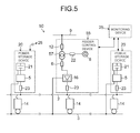
Fig. 5 is a block diagram illustrating the configuration of an electric railcar power feeding system according to a second embodiment. -
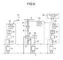
Fig. 6 is a block diagram illustrating the configuration of an electric railcar power feeding system according to a third embodiment. - An electric railcar power feeding system in an embodiment includes a power storage device, a rectifier, and an emergency power supply. The power storage device is connected to a feeder line for an electric railcar. The rectifier converts alternating-current power of a first power system to direct-current power and supply the direct-current power for the feeder line. The emergency power supply supplies power of a second power system different from the first power system for the feeder line.
- Hereinafter, embodiments will be described based on the drawings.
- As illustrated in
Fig. 1 , an electric railcarpower feeding system 10 in this embodiment is a power feeding system of a direct-current feeding type that feeds direct-current power toelectric railcars 14 via afeeder line 2 of a railroad, a monorail and so on. The electric railcarpower feeding system 10 includes a feeder control device (a power feeding device) 15,power storage devices 20, and amonitoring device 25 that collectively controls thefeeder control device 15 and thepower storage devices 20 as illustrated inFig. 1 . - The
feeder control device 15 is installed, for example, every 5 km or at every station of the railroad, monorail and so on. As illustrated inFig. 1 , thefeeder control device 15 mainly includes an alternating-current circuit breaker 12, atransformer 7, a normal powersupply circuit breaker 6, an emergency power supply 8(a power supply of a second power system), an emergency powersupply circuit breaker 22, arectifier 16, a direct-current circuit breaker 23 as feeding facilities. - The alternating-
current circuit breaker 12 electrically connects or disconnects an alternating-current power supply 9 being a commercial power supply and thetransformer 7 to/from each other. The aforementioned alternating-current power supply 9 (an alternating-current power supply of a first power system) is a normal power supply of an alternating-current system for direct-current feeding. Thetransformer 7 varies the voltage of the alternating-current power supply 9. The normal powersupply circuit breaker 6 electrically connects or disconnects thetransformer 7 and therectifier 16 to/from each other. - The emergency power supply 8 is, for example, a gas turbine generator or a diesel generator. The emergency power supply 8 supplies power of the second power system different from the first power system (an alternating-current power of the alternating-current power supply 9) for the
feeder line 2. The emergency powersupply circuit breaker 22 electrically connects or disconnects the emergency power supply 8 and therectifier 16 to/from each other. Note that a transformer for voltage regulation may be separately provided at the stage subsequent to the emergency power supply 8 such that the emergency power supply 8 and therectifier 16 are connected to each other via the separately provided transformer and the emergency powersupply circuit breaker 22. - The
rectifier 16 is, for example, a diode rectifier or a PWM converter, and is an AC/DC converter that converts alternating current to direct current. Therectifier 16 converts the alternating-current power of the first power system (the alternating-current power of the alternating-current power supply 9) to direct-current power and supply the direct-current power for thefeeder line 2. The direct-current circuit breaker 23 in thefeeder control device 15 electrically connects or disconnects therectifier 16 and thefeeder line 2 to/from each other. Note that those instruments in thefeeder control device 15 do not necessarily needs to be collectively arranged in the same device. - The
electric railcars 14 travel by receiving the direct-current power via thefeeder line 2 from thefeeder control device 15 side. All electric rolling stocks, which travel using electricity as a driving source such as vehicles used for the monorail and vehicles used for the railroad, correspond to theelectric railcars 14. Areturn feeder 3 is a conductor through which a return current flows and, for example, a rail in the case of the conventional railroad, has such function. For the transportation system that travels with rubber wheels and for part of subway, a dedicated conductor through which the return current flows is installed as thereturn feeder 3. - On the other hand, the
power storage devices 20 are arranged, for example, every 3 km in a distributed manner, and installed at a distance from the installation position of thefeeder control device 15. As illustrated inFig. 1 ,Fig. 2 , thepower storage device 20 is connected to thefeeder line 2 for an electric railcar. Further, thepower storage device 20 is connected to thereturn feeder 3. Thepower storage device 20 includes apower storage element 21, aconverter 5, and a direct-current circuit breaker 23. Thepower storage element 21 is, for example, a storage battery such as a lithium-ion battery, a nickel-metal hydride battery, or a lead-acid battery, or an energy storage element such as an electric double layer capacitor, or a flywheel. - The
power storage device 20 performs charge and discharge according to rise and drop in feeder line voltage respectively as will be described later. Thepower storage device 20 performs discharge when the value of the feeder line voltage is equal to or less than a discharge threshold (A1 to A2) that varies according to the state of charge (SOC) of thepower storage device 20 as illustrated, for example, inFig. 3 . Further, thepower storage device 20 performs charge when the value of the feeder line voltage is equal to or greater than a charge threshold (B1 to B2) that varies according to the state of charge (SOC) of thepower storage device 20. Further, thepower storage device 20 stops charge/discharge when the value of the feeder line voltage is greater than the discharge threshold A1 and less than the charge threshold B1, or stops charge/discharge when the state that the value of the feeder line voltage is greater than the discharge threshold A1 and less than the charge threshold B1 continues for a predetermined period. In other words, a voltage range S of the feeder line voltage inFig. 3 indicates a voltage range where thepower storage device 20 does not perform charge/discharge (a voltage range where theconverter 5 is stopped for gate block). - Note that the
power storage device 20 may be configured to stop charge/discharge when the value of current flowing through thefeeder line 2 or the value of the power is greater than a discharge threshold corresponding to the value of the current or the value of the power and less than the charge threshold. Instead of this, thepower storage device 20 may also be configured to stop charge/discharge when the state that the value of current flowing through thefeeder line 2 or the value of the power is greater than the discharge threshold corresponding to the value of the current or the value of the power and less than the charge threshold continues for a predetermined period. - The direct-
current circuit breaker 23 in thepower storage device 20 electrically connects or disconnects theconverter 5 and thefeeder line 2 to/from each other. Theconverter 5 sends/receive power to/from thefeeder line 2 and thepower storage element 21. Theconverter 5 is configured to have a function of a DC/DC converter if thepower storage element 21 is, for example, a storage battery or capacitor, and to have a function of an inverter that realizes DC/AC conversion if thepower storage element 21 is, for example, a flywheel. - Here, the
monitoring device 25 acquires, for example, the voltage of thefeeder line 2 and, according to an input operation by an operator based on the acquired feeder line voltage, controls the operations of the direct-current circuit breaker 23, the alternating-current circuit breaker 12, the normal powersupply circuit breaker 6, the emergency power supply 8, the emergency powersupply circuit breaker 22, and the direct-current circuit breaker 23 in thefeeder control device 15, and the direct-current circuit breaker 23 and theconverter 5 in thepower storage device 20. - Further, the
converter 5 will be described in detail. The converter 5 (a charge/discharge control unit) controls the charge and the discharge of thepower storage element 21 according to rise and drop in the voltage of thefeeder line 2. As illustrated inFig. 2 , theconverter 5 includes apower conversion unit 5a, acurrent control unit 5b, a charge/discharge management table 5c, a feeder linevoltage detection unit 5d, and a chargestate detection unit 5e. - The
power conversion unit 5a is configured as a step-up/down chopper circuit (buck-boost Converter) or the like that gate-drives, for example, a switching element, and controls the charge/discharge operation of thepower storage element 21. An example of the element to be applied to thepower conversion unit 5a is, for example, a self-arc-extinguishing element such as an IGBT (Insulated Gate Bipolar Transistor), and the charge/discharge operation of thepower storage element 21 is controlled by driving this kind of element in PWM (Pulse Width Modulation). - The
current control unit 5b controls the operation of the direct-current circuit breaker 23 in thepower storage device 20, while thepower conversion unit 5a controls the charge/discharge current (the charge current and the discharge current) that inputs/outputs from/to thefeeder line 2 to/from thepower storage element 21. The feeder linevoltage detection unit 5d detects the feeder line voltage of thefeeder line 2. The chargestate detection unit 5e detects the state of charge (SOC) of thepower storage element 21 as a charge rate [%]. - The charge/discharge management table 5c stores the correspondence between the feeder line voltage and the state of charge (SOC) of the
power storage element 21, as charge/discharge characteristics, in order to decide the discharge threshold voltage (A1 to A2) and the charge threshold voltage (B1 to B2) according to the feeder line voltage as illustrated inFig. 3, Fig. 4 . The charge/discharge management table 5c stores, for example, two kinds of charge/discharge characteristics different according to the power failure time of the alternating-current power supply 9 and the normal time when the power can be supplied from the alternating-current power supply 9. - More specifically, the
current control unit 5b varies the discharge threshold voltage and the charge threshold voltage on the basis of the detected feeder line voltage, the state of charge of thepower storage element 21, and the charge/discharge characteristics stored in the charge/discharge management table 5c as illustrated inFig. 3, Fig. 4 . Thecurrent control unit 5b thereby adjusts the charge/discharge current of thepower storage element 21 by thepower conversion unit 5a. - Here, a method of causing the electric railcar
power feeding system 10 to substantially independently operate will be described. First, in the case of normal feeding state in which the alternating-current power supply 9 is available, thepower storage device 20 performs charge/discharge according to the feeder line voltage. In more detail, thepower storage device 20 performs discharge when absorbing excessive regenerative power or when the feeder line voltage decreases, to stabilize the feeder line voltage. In this event, the emergency powersupply circuit breaker 22 in thefeeder control device 15 is kept open. The alternating-current power supply 9 passes through thetransformer 7 and is converted to direct-current power at therectifier 16, and is then supplied to theelectric railcars 14 via thefeeder line 2. - In the case where the alternating-
current power supply 9 fails in this situation and the alternating-current power supply 9 is separated from a feeder system to cause the electric railcarpower feeding system 10 independently operate, themonitoring device 25 controls the alternating-current circuit breaker 12 and the normal powersupply circuit breaker 6 to open the direct-current circuit breaker 23 in thefeeder control device 15. In this event, the direct-current circuit breakers 23 in thepower storage devices 20 may be opened in cooperation with the operation of thefeeder control device 15 to stop thepower storage devices 20. - On the other hand, the
monitoring device 25 performs controls to continue the charge/discharge operation without opening the direct-current circuit breakers 23 in thepower storage devices 20, thereby making it possible not to stop theelectric railcars 14 but to operate theelectric railcars 14, for example, to the nearest stations. Further, a low-loss device such as, for example, an SiC (Silicon Carbide) power device that is a high-efficiency device is applied to thepower storage device 20 so as to avoid a decrease in charge rate of the power storage element due to continuous generation of switching loss of theconverter 5 and an increase in storage capacity in consideration of the decrease, thereby simplifying the facilities. - On the other hand, a method of causing the electric railcar
power feeding system 10 to substantially independently operate, in the case where the direct-current circuit breaker 23 in thepower storage device 20 is opened to separate thepower storage device 20 from thefeeder line 2 to cause power failure in the whole feeder system, will be described. First, themonitoring device 25 performs control to activate the emergency power supply 8 and turn on (close) the emergency powersupply circuit breaker 22. Subsequently, the direct-current circuit breaker 23 in thefeeder control device 15 is turned on (closed) to supply the direct-current power to thefeeder line 2. Further, thepower storage device 20 is activated to turn on the direct-current circuit breaker 23 in thepower storage device 20 to cause thepower storage device 20 to cooperate with the feeder system. - In this event, the
power storage device 20 has characteristics of discharging when the feeder line voltage is decreased to be lower than the discharge threshold voltage as illustrated inFig. 3 . On the other hand, thepower storage device 20 gate-blocks theconverter 5 when not discharging, to stop the power conversion operation by theconverter 5. In this case, thepower storage device 20 may gate-block it upon detecting the fact that a predetermined time of a predetermined output value has elapsed or may gate-block it under the condition that the state of charge (SOC) reaches within a predetermined rage. - Further, the
power storage device 20 has characteristics of charging when the feeder line voltage rises to be higher than the charge threshold voltage as illustrated inFig. 3 . Further, the above-described charge threshold voltage has characteristics of decreasing as the state of charge (SOC) of thepower storage element 21 becomes lower, whereas increasing as the state of charge becomes higher. - Here, the electric railcar power feeding system is caused to independently operate simply by making the power storage device cooperate with the feeder system using a converter in the prior art. Therefore, in the prior art, when the feeder line voltage is tried to be maintained, the state of charge of the power storage device decreases due to switching loss of the converter, thus failing to secure energy to cause electric railcars to travel. Accordingly, to activate, for example, the electric railcars in a route all at once and move them to the nearest stations, it is necessary to increase the output of the power storage device itself according to the load in the prior art, resulting in increases in size of the power storage device and in cost.
- Hence, it is also possible to directly connect the power storage device to the feeder system without using the converter, but it is necessary to increase the number of series of cells in the power storage device. Therefore, in the prior art, the size of the power storage element increases and many power storage elements need to be arranged in a distributed manner in the feeder system to respond to the drop in the feeder line voltage, which is not economical. Further, in the case where the power storage element is directly connected to the feeder system without using the converter, the charge/discharge cannot be controlled, but the charge/discharge of the power storage element is performed at all times, causing charge/discharge loss. This results in an increase in power loss of the feeder system.
- On the other hand, the electric railcar
power feeding system 10 in this embodiment makes it possible to supply, for example, the power of the emergency power supply 8 to thefeeder line 2 via the diode rectifier, for a plurality ofelectric railcars 14 existing in the feeder system during the independent operation. In other words, the electric railcarpower feeding system 10 can generate power, for example, by a fuel system employing the emergency power supply 8 and therefore can supply power for a longer period than by the power storage element. Further, in the case of employing the diode rectifier with a high conversion efficiency as the rectifier, the above-described switching loss can be decreased. This makes it possible to supply power to an accessary system of theelectric railcar 14, for example, an air conditioner and illumination, and to continue the power supply to the accessary system for a long period until theelectric railcar 14 reaches, for example, the nearest station by the independent operation. - Here, in the case where the
electric railcar 14 travels to the nearest station, if theelectric railcar 14 exists near thefeeder control device 15, the feeder voltage drop hardly occurs because of low feeder circuit resistance, so that the movement of theelectric railcar 14 is considered to be relatively easy. However, if theelectric railcar 14 exists apart from thefeeder control device 15, the feeder voltage drop is considered to be large because of high feeder circuit resistance. - Hence, in the electric railcar
power feeding system 10 in this embodiment, thepower storage devices 20 arranged in a distributed manner are employed. Thepower storage device 20 normally charges/discharges according to the powering and regeneration of the electric railcar and therefore does not need to have a large power storage capacity, and a power storage element with small power storage capacity can be employed therefor. Further, thepower storage devices 20 with small power storage capacity are installed in a distributed manner and discharge only when the feeder voltage greatly drops, and can thereby suppress the decrease in the feeder voltage. In this event, the discharge threshold voltage is set to equal to or lower than a no-load delivery voltage of the rectifier when the emergency power supply is used. - Further, in the electric railcar
power feeding system 10, the main power is supplied from thefeeder control device 15 side, thus making it possible to operate thepower storage device 20 specialized for countermeasure of the voltage drop in the feeder line. Thus, in the electric railcarpower feeding system 10, the power storage capacity of thepower storage element 21 can be decreased, and the switching loss of theconverter 5 can be suppressed by gate block of theconverter 5 at the time when charge/discharge is not performed. - Further, the electric railcar
power feeding system 10 can charge the power generated by the emergency power supply 8 at the time when theelectric railcar 14 does not perform powering operation due to the decrease in the charge threshold voltage when the state of charge of thepower storage device 20 is decreased, and thereby can restore the state of charge (SOC) of thepower storage device 20. - Furthermore, the electric railcar
power feeding system 10 can supply power from thefeeder control device 15 side for a small load capacity such as an accessary load of theelectric railcar 14, whereas supply power from thepower storage device 20 side when the feeder line voltage (trolley voltage) is decreased due to a large powering load. This facilitates the maintenance of the feeder line voltage, and thereby makes it possible to decrease the power storage capacity of the power storage element and decrease the switching loss of the power storage device in the independent operation, resulting in simplification of the facilities for power feeding. As has been described, according to the electric railcarpower feeding system 10 in this embodiment, it becomes possible to supply necessary power to the feeder line side even in emergency such as power failure, by using relatively simple facilities. - Next, a second embodiment will be described based on
Fig. 5 . Note that components which are the same as those in the first embodiment illustrated inFig. 1 are denoted by the same reference numerals inFig. 5 , and overlapped description thereof will be omitted. - As illustrated in
Fig. 5 , an electric railcarpower feeding system 50 in this embodiment includes afeeder control device 55 in place of thefeeder control device 15 included in the electric railcarpower feeding system 10 according to the first embodiment. Thefeeder control device 55 includes atransformer 57 in place of thetransformer 7 included in thefeeder control device 15. The electric railcarpower feeding system 50 realizes voltage transformation of the alternating-current power supply 9 and voltage transformation of the emergency power supply 8 using onetransformer 57 in common for reduction of facilities. Thetransformer 57 transforms the alternating-current power of the alternating-current power supply 9 (the alternating-current power of the first power system) or the power of the emergency power supply 8 (the power of the second power system) so as to output the transformed power for therectifier 16. - More specifically, the
transformer 57 includes a tap with a transformation ratio according to the alternating-current power supply 9 and a tap with a transformation ratio according to the emergency power supply 8. Thetransformer 57 employs the latter tap in the independent operation to output the power of the emergency power supply 8 to therectifier 16 side as illustrated inFig. 5 . Therefore, according to the electric railcarpower feeding system 50, common use of thetransformer 57 enables reduction of facilities and cost. Further, the electric railcarpower feeding system 50 can perform the voltage transformation of the emergency power supply 8, which cannot be performed by the electric railcarpower feeding system 10 in the first embodiment, thereby broadening the options of the employable emergency power supply 8. - Next, a third embodiment will be described based on
Fig. 6 . Note that components which are the same as those in the first embodiment illustrated inFig. 1 are denoted by the same reference numerals inFig. 6 , and overlapped description thereof will be omitted. - An electric railcar
power feeding system 70 according to this embodiment includes afeeder control device 75 in place of thefeeder control device 15 included in the electric railcarpower feeding system 10 according to the first embodiment. Thefeeder control device 75 includes anemergency power supply 78 in place of the emergency power supply 8 included in thefeeder control device 15. Thetransformer 7 and therectifier 16 are opened by the direct-current circuit breaker 23 in thefeeder control device 75 when the alternating-current power supply 9 fails, as in the case of the first embodiment. - The
emergency power supply 78 is connected to thefeeder line 2 with no transformer intervening between them and is, for example, a power storage element composed of the number of cells in series corresponding to a DC 1500 V. Accordingly, the battery capacity of theemergency power supply 78 is necessarily large. Theemergency power supply 78 composed of the power storage element can be made to operate in place of the emergency power supply 8 is in the first embodiment. - More specifically, it becomes possible that when the alternating-
current power supply 9 fails, theemergency power supply 78 supplies the main feeder power to thefeeder line 2, whereas thepower storage device 20 smaller in power storage capacity than theemergency power supply 78 performs compensation for the drop in the feeder line voltage (trolley voltage). This makes it possible to reduce the facilities of the electric railcarpower feeding system 70 including thefeeder control device 75. Note that to prevent the situation that discharge is started immediately after the failure of the alternating-current system, theemergency power supply 78 having the power storage element may be paralleled-off once from thefeeder line 2 when the alternating-current power supply 9 fails. - While certain embodiments have been described, these embodiments have been presented by way of example only, and are not intended to limit the scope of the inventions. Indeed, the novel embodiments described herein may be embodied in a variety of other forms; furthermore, various omissions, substitutions and changes in the form of the embodiments described herein may be made without departing from the spirit of the inventions. The accompanying claims and their equivalents are intended to cover such forms or modifications as would fall within the scope and spirit of the inventions.
- It is explicitly stated that all features disclosed in the description and/or the claims are intended to be disclosed separately and independently from each other for the purpose of original disclosure as well as for the purpose of restricting the claimed invention independent of the composition of the features in the embodiments and/or the claims. It is explicitly stated that all value ranges or indications of groups of entities disclose every possible intermediate value or intermediate entity for the purpose of original disclosure as well as for the purpose of restricting the claimed invention, in particular as limits of value ranges.
Claims (14)
- An electric railcar power feeding system (10; 50; 70) comprising:a power storage device (20) connected to a feeder line (2) for an electric railcar (14);a rectifier (16) configured to convert alternating-current power of a first power system to direct-current power and supply the direct-current power for the feeder line (2); andan emergency power supply (8; 78) configured to supply power of a second power system different from the first power system for the feeder line (2).
- The electric railcar power feeding system (10; 50; 70) according to claim 1,
wherein the power storage device (20) is configured to perform charge and discharge according to rise and drop in feeder line voltage respectively. - The electric railcar power feeding system (10; 50; 70) according to claim 2,
wherein the power storage device (20) is configured to perform discharge when a value of the feeder line voltage is equal to or less than a discharge threshold (A1, A2) that varies according to a state of charge (SOC) of the power storage device (20). - The electric railcar power feeding system (10; 50; 70) according to claim 2 or 3,
wherein the power storage device (20) is configured to perform charge when a value of the feeder line voltage is equal to or greater than a charge threshold (B1, B2) that varies according to a state of charge (SOC) of the power storage device (20). - The electric railcar power feeding system (10; 50; 70) according to claim 2,
wherein the power storage device (20) is configured to stop charge/discharge when the value of the feeder line voltage is greater than the discharge threshold (A1) and less than the charge threshold (B1), or is configured to stop charge/discharge when a state that the value of the feeder line voltage is greater than the discharge threshold (A1) and less than the charge threshold (B1) continues for a predetermined period. - The electric railcar power feeding system (10; 50; 70) according to claim 1,
wherein the power storage device (20) is configured to stop charge/discharge when a value of current flowing through the feeder line (2) or a value of the power is greater than a discharge threshold (A1) corresponding to the value of the current or the value of the power and less than a charge threshold (B1), or is configured to stop charge/discharge when a state that the value of current flowing through the feeder line (2) or the value of the power is greater than the discharge threshold (A1) corresponding to the value of the current or the value of the power and less than the charge threshold (B1) continues for a predetermined period. - The electric railcar power feeding system (10; 50; 70) according to any one of claim 1 to 6,
wherein the power storage device (20) comprises a power storage element (21) and a step-up/down chopper circuit (5a), and
wherein the power storage element (21) is an energy storage element. - The electric railcar power feeding system (10; 50; 70) according to claim 7,
wherein an SiC power device is applied to the step-up/down chopper circuit (5a). - The electric railcar power feeding system (10; 50) according to any one of claim 1 to 8,
wherein the emergency power supply (8) is a power supply that generates power by rotating an alternating-current generator, and
wherein the power generated by the alternating-current generator is outputted through the rectifier (16). - The electric railcar power feeding system (10; 50; 70) according to any one of claim 1 to 9, further comprising:a transformer (57) configured to transform the alternating-current power of the first power system or the power of the emergency power supply (8) so as to output the transformed power for the rectifier (16).
- The electric railcar power feeding system (10; 50; 70) according to any one of claim 1 to 10,
wherein the emergency power supply (78) comprises a power storage element. - The electric railcar power feeding system (70) according to claim 11,
wherein the emergency power supply (78) comprising the power storage element is paralleled-off once from the feeder line (2) when the alternating-current power supply (9) fails. - A power feeding device (15; 55; 75) used for an electric railcar power feeding system (10; 50; 70), the electric railcar power feeding system (10; 50; 70) comprising: a power storage device (20) connected to a feeder line (2); and a rectifier (16) configured to convert alternating-current power of a first power system to direct-current power and supply the direct-current power for the feeder line (2), the power feeding device (15; 55; 75) comprising:an emergency power supply (8; 78) configured to supply power of a second power system different from the first power system for the feeder line (2) used for an electric railcar (14).
- A power storage device (20) used for the electric railcar power feeding system (10; 50; 70) according to claim 1, comprising:a power storage element (21); anda charge/discharge control unit (5) configured to control a charge and discharge of the power storage element (21) according to rise and drop in the voltage of the feeder line (2).
Applications Claiming Priority (1)
| Application Number | Priority Date | Filing Date | Title |
|---|---|---|---|
| JP2013167820A JP5735061B2 (en) | 2013-08-12 | 2013-08-12 | Train power supply system |
Publications (2)
| Publication Number | Publication Date |
|---|---|
| EP2837525A2 true EP2837525A2 (en) | 2015-02-18 |
| EP2837525A3 EP2837525A3 (en) | 2015-12-02 |
Family
ID=51359270
Family Applications (1)
| Application Number | Title | Priority Date | Filing Date |
|---|---|---|---|
| EP14180226.4A Withdrawn EP2837525A3 (en) | 2013-08-12 | 2014-08-07 | Electric railcar power feeding system, power feeding device, and power storage device |
Country Status (6)
| Country | Link |
|---|---|
| US (1) | US9873335B2 (en) |
| EP (1) | EP2837525A3 (en) |
| JP (1) | JP5735061B2 (en) |
| CN (1) | CN104369677B (en) |
| BR (1) | BR102014019747A2 (en) |
| HK (1) | HK1203176A1 (en) |
Cited By (4)
| Publication number | Priority date | Publication date | Assignee | Title |
|---|---|---|---|---|
| WO2017060444A1 (en) * | 2015-10-07 | 2017-04-13 | Abb Schweiz Ag | Arrangement and method for transforming a voltage |
| RU2636847C1 (en) * | 2016-08-03 | 2017-11-28 | Илья Александрович Кондрашов | Dc traction substation with flywheel storage |
| DE102018105300A1 (en) * | 2018-03-08 | 2019-09-12 | Paul Vahle Gmbh & Co. Kg | DC TRANSMISSION OVER POWER RAILS |
| WO2023094975A1 (en) * | 2021-11-23 | 2023-06-01 | Dmowska Andrzejuk Danuta | A dc traction power supply method and system |
Families Citing this family (27)
| Publication number | Priority date | Publication date | Assignee | Title |
|---|---|---|---|---|
| JP2554666B2 (en) | 1987-09-18 | 1996-11-13 | 株式会社ニチリョー | Variable pipette |
| DK3405388T3 (en) * | 2016-01-20 | 2020-05-18 | Siemens Ag | Energy management system for a vessel |
| CN105846513A (en) * | 2016-05-30 | 2016-08-10 | 谢宗洺 | Complete-set charging device for energy-saving electric vehicle |
| DE102016214051A1 (en) * | 2016-07-29 | 2018-02-01 | Siemens Aktiengesellschaft | Method for power supply and power supply for arranged on a railway track operating elements |
| CN106809026B (en) * | 2016-09-21 | 2018-08-14 | 比亚迪股份有限公司 | The braking recovery system and method for train, energy-accumulating power station and control centre |
| CN106809032B (en) * | 2016-09-21 | 2019-04-19 | 比亚迪股份有限公司 | Brake recovery system and method for train |
| CN106809024B (en) * | 2016-09-21 | 2019-04-19 | 比亚迪股份有限公司 | Brake recovery system and method for train and train |
| CN106809021B (en) * | 2016-09-21 | 2018-09-11 | 比亚迪股份有限公司 | Braking recovery system, the control centre for train scheduling and the method for train |
| CN106809029B (en) * | 2016-09-21 | 2018-09-07 | 比亚迪股份有限公司 | Braking recovery system, the control centre for train scheduling and the method for train |
| CN106809025B (en) * | 2016-09-21 | 2019-02-26 | 比亚迪股份有限公司 | Brake recovery system for train, control center for train dispatch and method |
| CN106809022B (en) * | 2016-09-21 | 2018-08-14 | 比亚迪股份有限公司 | The braking recovery system and method for train and the control centre for controlling train operation |
| CN106809027B (en) * | 2016-09-21 | 2018-12-21 | 比亚迪股份有限公司 | The braking recovery system and method and train of train |
| CN106809031B (en) * | 2016-09-21 | 2018-01-23 | 比亚迪股份有限公司 | Braking recovery system, the control centre for train scheduling and the method for train |
| CN106809030B (en) * | 2016-09-21 | 2018-09-07 | 比亚迪股份有限公司 | Braking recovery system, the control centre for train scheduling and the method for train |
| CN106809060B (en) * | 2016-09-21 | 2018-01-23 | 比亚迪股份有限公司 | The traction power source system and its control method of Rail Transit System |
| CN106953332B (en) * | 2017-05-02 | 2019-07-16 | 中国矿业大学 | In-phase power supply scheme for electrified railway based on uncontrolled rectification and step-wave synthesis inverter |
| JP6812314B2 (en) * | 2017-07-21 | 2021-01-13 | 株式会社日立製作所 | Railway system controls and methods |
| JP6993803B2 (en) * | 2017-07-26 | 2022-01-14 | 株式会社東芝 | Regenerative control system for electric railways |
| JP7059626B2 (en) * | 2017-12-26 | 2022-04-26 | 株式会社Gsユアサ | Railway power storage device |
| JP7059627B2 (en) * | 2017-12-26 | 2022-04-26 | 株式会社Gsユアサ | Railway power storage device |
| DE102018113250A1 (en) * | 2018-06-04 | 2019-12-05 | Volkswagen Aktiengesellschaft | Oberleitungsanordnung for a two-pole overhead line |
| CN110676833B (en) * | 2018-07-02 | 2021-12-07 | 比亚迪股份有限公司 | Track energy feedback system and control method thereof |
| EP3696009B1 (en) * | 2019-02-12 | 2024-09-04 | Furrer + Frey AG | Method for symmetrising a three phase current |
| CN110011408B (en) * | 2019-05-21 | 2024-03-08 | 国网福建省电力有限公司宁德供电公司 | A mobile emergency power supply system and its working method |
| CN112009250B (en) * | 2020-08-22 | 2025-03-18 | 中车长春轨道客车股份有限公司 | A subway vehicle train activation circuit and control method |
| CN113787909B (en) * | 2021-08-04 | 2023-06-23 | 中车唐山机车车辆有限公司 | Power supply device and rail vehicle |
| JP2024098415A (en) * | 2023-01-10 | 2024-07-23 | 株式会社東芝 | Power supply device |
Family Cites Families (11)
| Publication number | Priority date | Publication date | Assignee | Title |
|---|---|---|---|---|
| JP3964857B2 (en) | 2003-12-04 | 2007-08-22 | 株式会社日立製作所 | Regenerative power absorption control method for electric railways |
| JP4238190B2 (en) * | 2004-08-26 | 2009-03-11 | 株式会社日立製作所 | Power storage type regenerative power absorber and control method thereof |
| JP2008022650A (en) * | 2006-07-13 | 2008-01-31 | Univ Of Tsukuba | Self-sustained operation support device and power supply system |
| US8598739B2 (en) | 2008-02-29 | 2013-12-03 | Kawasaki Jukogyo Kabushiki Kaisha | Electric railway power-supply system |
| JP5187624B2 (en) * | 2008-06-30 | 2013-04-24 | 川崎重工業株式会社 | Microgrid using electric railway system |
| JP5331461B2 (en) | 2008-11-27 | 2013-10-30 | 株式会社東芝 | Railway vehicle drive system |
| JP2012105407A (en) * | 2010-11-08 | 2012-05-31 | Toshiba Corp | Power storage system |
| US8737104B2 (en) | 2011-01-17 | 2014-05-27 | Mitsubishi Electric Corporation | Switching power supply device |
| JP5377538B2 (en) | 2011-02-14 | 2013-12-25 | 株式会社東芝 | Power storage device and its installation / operation method |
| JP2013018464A (en) | 2011-07-14 | 2013-01-31 | Kawasaki Heavy Ind Ltd | Feeding system of electric railroad including electric storage device |
| US9030852B2 (en) * | 2012-05-31 | 2015-05-12 | General Electric Company | System for power conversion utilizing matrix converters |
-
2013
- 2013-08-12 JP JP2013167820A patent/JP5735061B2/en active Active
-
2014
- 2014-08-05 US US14/451,701 patent/US9873335B2/en not_active Expired - Fee Related
- 2014-08-07 EP EP14180226.4A patent/EP2837525A3/en not_active Withdrawn
- 2014-08-08 BR BR102014019747A patent/BR102014019747A2/en not_active Application Discontinuation
- 2014-08-12 CN CN201410393718.1A patent/CN104369677B/en active Active
-
2015
- 2015-04-15 HK HK15103679.5A patent/HK1203176A1/en unknown
Non-Patent Citations (1)
| Title |
|---|
| None |
Cited By (4)
| Publication number | Priority date | Publication date | Assignee | Title |
|---|---|---|---|---|
| WO2017060444A1 (en) * | 2015-10-07 | 2017-04-13 | Abb Schweiz Ag | Arrangement and method for transforming a voltage |
| RU2636847C1 (en) * | 2016-08-03 | 2017-11-28 | Илья Александрович Кондрашов | Dc traction substation with flywheel storage |
| DE102018105300A1 (en) * | 2018-03-08 | 2019-09-12 | Paul Vahle Gmbh & Co. Kg | DC TRANSMISSION OVER POWER RAILS |
| WO2023094975A1 (en) * | 2021-11-23 | 2023-06-01 | Dmowska Andrzejuk Danuta | A dc traction power supply method and system |
Also Published As
| Publication number | Publication date |
|---|---|
| EP2837525A3 (en) | 2015-12-02 |
| CN104369677A (en) | 2015-02-25 |
| JP2015036280A (en) | 2015-02-23 |
| CN104369677B (en) | 2017-06-23 |
| JP5735061B2 (en) | 2015-06-17 |
| US20150045997A1 (en) | 2015-02-12 |
| BR102014019747A2 (en) | 2015-09-22 |
| US9873335B2 (en) | 2018-01-23 |
| HK1203176A1 (en) | 2015-10-23 |
Similar Documents
| Publication | Publication Date | Title |
|---|---|---|
| US9873335B2 (en) | Electric railcar power feeding system, power feeding device, and power storage device | |
| KR101715444B1 (en) | Battery device and method for installing and operating same | |
| EP2241472B1 (en) | Power storage control apparatus and method of electric vehicle | |
| US9227516B2 (en) | Electric vehicle propulsion control device and railway vehicle system | |
| JP3964857B2 (en) | Regenerative power absorption control method for electric railways | |
| EP2230123A2 (en) | Railway system including power feeding equipment installed on railway track between stations | |
| JP3618273B2 (en) | DC feeder system for electric railway | |
| JP4415874B2 (en) | Charge and discharge method for transportation system | |
| JP5777669B2 (en) | Electric vehicle control device | |
| EP3556604B1 (en) | Station building power supply device | |
| WO2017104204A1 (en) | Vehicle | |
| JP6786268B2 (en) | Power storage system | |
| US10056841B2 (en) | Energy storage arrangement, energy storage system and method for operating an energy storage arrangement | |
| JP5509442B2 (en) | Power converter and electric railway system | |
| JP6703913B2 (en) | Power storage device | |
| JP7301686B2 (en) | power conversion system | |
| JP7301684B2 (en) | power conversion system | |
| HK1189198B (en) | Battery device and method for installing and operating same | |
| JP2006340468A (en) | Electric vehicle control device | |
| JP2021044980A (en) | Power conversion system | |
| JP2013046546A (en) | Power conversion system |
Legal Events
| Date | Code | Title | Description |
|---|---|---|---|
| 17P | Request for examination filed |
Effective date: 20140807 |
|
| AK | Designated contracting states |
Kind code of ref document: A2 Designated state(s): AL AT BE BG CH CY CZ DE DK EE ES FI FR GB GR HR HU IE IS IT LI LT LU LV MC MK MT NL NO PL PT RO RS SE SI SK SM TR |
|
| AX | Request for extension of the european patent |
Extension state: BA ME |
|
| PUAI | Public reference made under article 153(3) epc to a published international application that has entered the european phase |
Free format text: ORIGINAL CODE: 0009012 |
|
| PUAL | Search report despatched |
Free format text: ORIGINAL CODE: 0009013 |
|
| AK | Designated contracting states |
Kind code of ref document: A3 Designated state(s): AL AT BE BG CH CY CZ DE DK EE ES FI FR GB GR HR HU IE IS IT LI LT LU LV MC MK MT NL NO PL PT RO RS SE SI SK SM TR |
|
| AX | Request for extension of the european patent |
Extension state: BA ME |
|
| RIC1 | Information provided on ipc code assigned before grant |
Ipc: B60M 3/02 20060101ALN20151026BHEP Ipc: B60M 3/06 20060101AFI20151026BHEP |
|
| RBV | Designated contracting states (corrected) |
Designated state(s): AL AT BE BG CH CY CZ DE DK EE ES FI FR GB GR HR HU IE IS IT LI LT LU LV MC MK MT NL NO PL PT RO RS SE SI SK SM TR |
|
| STAA | Information on the status of an ep patent application or granted ep patent |
Free format text: STATUS: THE APPLICATION HAS BEEN WITHDRAWN |
|
| 18W | Application withdrawn |
Effective date: 20161019 |