EP2837515A2 - Vehicle cooling system - Google Patents
Vehicle cooling system Download PDFInfo
- Publication number
- EP2837515A2 EP2837515A2 EP14178755.6A EP14178755A EP2837515A2 EP 2837515 A2 EP2837515 A2 EP 2837515A2 EP 14178755 A EP14178755 A EP 14178755A EP 2837515 A2 EP2837515 A2 EP 2837515A2
- Authority
- EP
- European Patent Office
- Prior art keywords
- heat exchanger
- baffle plate
- cooling system
- vehicle cooling
- actuator
- Prior art date
- Legal status (The legal status is an assumption and is not a legal conclusion. Google has not performed a legal analysis and makes no representation as to the accuracy of the status listed.)
- Granted
Links
Images
Classifications
-
- B—PERFORMING OPERATIONS; TRANSPORTING
- B60—VEHICLES IN GENERAL
- B60H—ARRANGEMENTS OF HEATING, COOLING, VENTILATING OR OTHER AIR-TREATING DEVICES SPECIALLY ADAPTED FOR PASSENGER OR GOODS SPACES OF VEHICLES
- B60H1/00—Heating, cooling or ventilating devices
- B60H1/00007—Combined heating, ventilating, or cooling devices
- B60H1/00021—Air flow details of HVAC devices
-
- B—PERFORMING OPERATIONS; TRANSPORTING
- B60—VEHICLES IN GENERAL
- B60K—ARRANGEMENT OR MOUNTING OF PROPULSION UNITS OR OF TRANSMISSIONS IN VEHICLES; ARRANGEMENT OR MOUNTING OF PLURAL DIVERSE PRIME-MOVERS IN VEHICLES; AUXILIARY DRIVES FOR VEHICLES; INSTRUMENTATION OR DASHBOARDS FOR VEHICLES; ARRANGEMENTS IN CONNECTION WITH COOLING, AIR INTAKE, GAS EXHAUST OR FUEL SUPPLY OF PROPULSION UNITS IN VEHICLES
- B60K11/00—Arrangement in connection with cooling of propulsion units
- B60K11/02—Arrangement in connection with cooling of propulsion units with liquid cooling
- B60K11/04—Arrangement or mounting of radiators, radiator shutters, or radiator blinds
-
- B—PERFORMING OPERATIONS; TRANSPORTING
- B60—VEHICLES IN GENERAL
- B60K—ARRANGEMENT OR MOUNTING OF PROPULSION UNITS OR OF TRANSMISSIONS IN VEHICLES; ARRANGEMENT OR MOUNTING OF PLURAL DIVERSE PRIME-MOVERS IN VEHICLES; AUXILIARY DRIVES FOR VEHICLES; INSTRUMENTATION OR DASHBOARDS FOR VEHICLES; ARRANGEMENTS IN CONNECTION WITH COOLING, AIR INTAKE, GAS EXHAUST OR FUEL SUPPLY OF PROPULSION UNITS IN VEHICLES
- B60K11/00—Arrangement in connection with cooling of propulsion units
- B60K11/08—Air inlets for cooling; Shutters or blinds therefor
- B60K11/085—Air inlets for cooling; Shutters or blinds therefor with adjustable shutters or blinds
-
- F—MECHANICAL ENGINEERING; LIGHTING; HEATING; WEAPONS; BLASTING
- F01—MACHINES OR ENGINES IN GENERAL; ENGINE PLANTS IN GENERAL; STEAM ENGINES
- F01P—COOLING OF MACHINES OR ENGINES IN GENERAL; COOLING OF INTERNAL-COMBUSTION ENGINES
- F01P7/00—Controlling of coolant flow
- F01P7/02—Controlling of coolant flow the coolant being cooling-air
- F01P7/10—Controlling of coolant flow the coolant being cooling-air by throttling amount of air flowing through liquid-to-air heat exchangers
-
- B—PERFORMING OPERATIONS; TRANSPORTING
- B60—VEHICLES IN GENERAL
- B60H—ARRANGEMENTS OF HEATING, COOLING, VENTILATING OR OTHER AIR-TREATING DEVICES SPECIALLY ADAPTED FOR PASSENGER OR GOODS SPACES OF VEHICLES
- B60H1/00—Heating, cooling or ventilating devices
- B60H1/00007—Combined heating, ventilating, or cooling devices
- B60H1/00021—Air flow details of HVAC devices
- B60H2001/00078—Assembling, manufacturing or layout details
- B60H2001/00092—Assembling, manufacturing or layout details of air deflecting or air directing means inside the device
-
- B—PERFORMING OPERATIONS; TRANSPORTING
- B60—VEHICLES IN GENERAL
- B60K—ARRANGEMENT OR MOUNTING OF PROPULSION UNITS OR OF TRANSMISSIONS IN VEHICLES; ARRANGEMENT OR MOUNTING OF PLURAL DIVERSE PRIME-MOVERS IN VEHICLES; AUXILIARY DRIVES FOR VEHICLES; INSTRUMENTATION OR DASHBOARDS FOR VEHICLES; ARRANGEMENTS IN CONNECTION WITH COOLING, AIR INTAKE, GAS EXHAUST OR FUEL SUPPLY OF PROPULSION UNITS IN VEHICLES
- B60K11/00—Arrangement in connection with cooling of propulsion units
- B60K11/08—Air inlets for cooling; Shutters or blinds therefor
-
- B—PERFORMING OPERATIONS; TRANSPORTING
- B60—VEHICLES IN GENERAL
- B60Y—INDEXING SCHEME RELATING TO ASPECTS CROSS-CUTTING VEHICLE TECHNOLOGY
- B60Y2200/00—Type of vehicle
- B60Y2200/20—Off-Road Vehicles
- B60Y2200/22—Agricultural vehicles
- B60Y2200/221—Tractors
-
- B—PERFORMING OPERATIONS; TRANSPORTING
- B60—VEHICLES IN GENERAL
- B60Y—INDEXING SCHEME RELATING TO ASPECTS CROSS-CUTTING VEHICLE TECHNOLOGY
- B60Y2200/00—Type of vehicle
- B60Y2200/40—Special vehicles
- B60Y2200/41—Construction vehicles, e.g. graders, excavators
-
- F—MECHANICAL ENGINEERING; LIGHTING; HEATING; WEAPONS; BLASTING
- F01—MACHINES OR ENGINES IN GENERAL; ENGINE PLANTS IN GENERAL; STEAM ENGINES
- F01P—COOLING OF MACHINES OR ENGINES IN GENERAL; COOLING OF INTERNAL-COMBUSTION ENGINES
- F01P3/00—Liquid cooling
- F01P3/18—Arrangements or mounting of liquid-to-air heat-exchangers
- F01P2003/182—Arrangements or mounting of liquid-to-air heat-exchangers with multiple heat-exchangers
-
- Y—GENERAL TAGGING OF NEW TECHNOLOGICAL DEVELOPMENTS; GENERAL TAGGING OF CROSS-SECTIONAL TECHNOLOGIES SPANNING OVER SEVERAL SECTIONS OF THE IPC; TECHNICAL SUBJECTS COVERED BY FORMER USPC CROSS-REFERENCE ART COLLECTIONS [XRACs] AND DIGESTS
- Y02—TECHNOLOGIES OR APPLICATIONS FOR MITIGATION OR ADAPTATION AGAINST CLIMATE CHANGE
- Y02T—CLIMATE CHANGE MITIGATION TECHNOLOGIES RELATED TO TRANSPORTATION
- Y02T10/00—Road transport of goods or passengers
- Y02T10/80—Technologies aiming to reduce greenhouse gasses emissions common to all road transportation technologies
- Y02T10/88—Optimized components or subsystems, e.g. lighting, actively controlled glasses
Definitions
- the present invention relates to a vehicle cooling system.
- the vehicle cooling system comprises a first heat exchanger having a first end and a second end positioned opposite from the first end.
- a cooling fan is spaced apart from the first heat exchanger.
- a second heat exchanger extends between the cooling fan and the first end of the first heat exchanger.
- a third heat exchanger is spaced apart from the second heat exchanger and extends between the cooling fan and the second end of the first heat exchanger.
- a baffle plate is pivotally mounted to the vehicle cooling system, the baffle plate has a pivot axis positioned adjacent to the first end of the first heat exchanger, the baffle plate being pivotal to a first position reducing air flow through the first heat exchanger and to a second position reducing air flow through the second heat exchanger.
- An actuator is provided for pivoting the baffle plate about the pivot axis.
- the baffle plate can minimize fan power through the vehicle cooling system by directing air flow to the heat exchangers that need it.
- the baffle plate is movable so that it can be used to strategically direct air flow. Because the baffle plate sits between the two air flow streams coming from the first and second heat exchangers, the losses that would occur by simply closing off portions of a heat exchanger are minimized. Also, because the entire heat exchanger is still getting some air flow, the heat load is still more balanced than if air flow was shut-off to a portion of the heat exchanger. If air flow is shut-off to a portion of the heat exchanger, the heat exchanger ends up with a large thermal gradient across the heat exchanger, which generally decreases its life.
- a vehicle cooling system 10 is provided for a work vehicle (not shown).
- the vehicle cooling system 10 includes a first frame 12 which supports a front or first heat exchanger 14, such as a vehicle radiator. Both the first frame 12 and the first heat exchanger 14 have a lower or first end 16 and an upper or second end 18 which are positioned opposite from each other.
- a cooling fan 20 is spaced apart from the first heat exchanger 14, and is surrounded by a fan frame 22.
- a second heat exchanger 24 extends between the cooling fan 20 and the first end 16 of the first heat exchanger 14.
- the second heat exchanger 24 is supported by a second frame 26.
- Second frame 26 includes a front member 28, a left side member 30, a right side member 32 and a rear member 34.
- Upper or third heat exchanger 40 is spaced apart from the second heat exchanger 24 and extends between the cooling fan 20 and the second end 18 of the first heat exchanger 14.
- the third heat exchanger 40 is supported by a third frame 42 which extends between the second end 18 of the first frame 12 and an upper end of the fan frame 22.
- a pivoting baffle assembly 50 includes a base plate 52 which is fixed to a central portion of front member 28 of second frame 26.
- a baffle plate 54 has an inner end pivotally coupled to an upper end of the base plate 52.
- An actuator arm 56 projects from the inner end of baffle plate 54 and is at an angle with respect to baffle plate 54.
- the baffle plate 54 has a pivot axis positioned adjacent to the first end 16 of the first heat exchanger 14. The baffle plate 54 extends into a space 55 which is enclosed by the vehicle cooling system 10.
- An actuator comprising a linear actuator 58 has a first end or cylinder housing 60 pivotally coupled to the left side member 30 of second frame 26, and a second end or rod 62 pivotally coupled to the actuator arm 56.
- the linear actuator 58 is preferable a hydraulic cylinder.
- flanges 64 and 66 project upwardly from an upper portion of front member 28 of second frame 26.
- the base plate 52 is attached to the flanges 64 and 66.
- the base plate 52 is pivotally coupled to baffle plate 54 by a hinge 68.
- the actuator arm 56 projects rearwardly from one side of the baffle plate 54.
- the baffle plate 54 When the linear actuator 58 is fully extended in a first position, the baffle plate 54 will be adjacent to the first heat exchanger 14 and will reduce the amount of air flow through the first heat exchanger 14. When the linear actuator 58 is fully retracted in a second position, the baffle plate 54 will be adjacent to the second heat exchanger 24 and will reduce the amount of air flow through the second heat exchanger 24.
- the movable baffle plate 54 can be electronically controlled by means of the linear actuator 58 using sensors (not shown) to determine which of the heat exchangers 14, 24 and 40 need more air flow than others.
Landscapes
- Engineering & Computer Science (AREA)
- Mechanical Engineering (AREA)
- Chemical & Material Sciences (AREA)
- Combustion & Propulsion (AREA)
- Transportation (AREA)
- General Engineering & Computer Science (AREA)
- Physics & Mathematics (AREA)
- Thermal Sciences (AREA)
- Cooling, Air Intake And Gas Exhaust, And Fuel Tank Arrangements In Propulsion Units (AREA)
Abstract
Description
- The present invention relates to a vehicle cooling system.
- It is known to provide work vehicles, such as agricultural tractors, with a vehicle cooling system wherein a plurality of coolers or heat exchangers are positioned on different sides of a volume adjacent to a cooling fan. In such a multi-faced cooling system, it is difficult to properly balance the air flow through all the heat exchangers. Some of the heat exchangers may have too much air flow, while others in the system may have too little air flow. Any excess air flow through a heat exchanger results in wasted power consumed by the cooling fan that could otherwise be used for productive work of the work vehicle. In addition, different vehicle operations may benefit from varying the air flows in such a vehicle cooling system.
- Therefore, what is needed in the art is a vehicle cooling system with improved air flow.
- This and other objects are achieved by the present invention, wherein a vehicle cooling system is provided. The vehicle cooling system comprises a first heat exchanger having a first end and a second end positioned opposite from the first end. A cooling fan is spaced apart from the first heat exchanger. A second heat exchanger extends between the cooling fan and the first end of the first heat exchanger. A third heat exchanger is spaced apart from the second heat exchanger and extends between the cooling fan and the second end of the first heat exchanger. A baffle plate is pivotally mounted to the vehicle cooling system, the baffle plate has a pivot axis positioned adjacent to the first end of the first heat exchanger, the baffle plate being pivotal to a first position reducing air flow through the first heat exchanger and to a second position reducing air flow through the second heat exchanger. An actuator is provided for pivoting the baffle plate about the pivot axis.
- As a result, the baffle plate can minimize fan power through the vehicle cooling system by directing air flow to the heat exchangers that need it. The baffle plate is movable so that it can be used to strategically direct air flow. Because the baffle plate sits between the two air flow streams coming from the first and second heat exchangers, the losses that would occur by simply closing off portions of a heat exchanger are minimized. Also, because the entire heat exchanger is still getting some air flow, the heat load is still more balanced than if air flow was shut-off to a portion of the heat exchanger. If air flow is shut-off to a portion of the heat exchanger, the heat exchanger ends up with a large thermal gradient across the heat exchanger, which generally decreases its life.
- For a complete understanding of the objects, techniques, and structure of the invention reference should be made to the following detailed description and accompanying drawings, wherein similar components are designated by identical reference numerals:
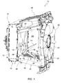
- Fig. 1
- is a perspective view of a vehicle cooling system with a pivoting baffle assembly, embodying the invention,
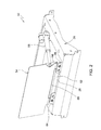
- Fig. 2
- is a perspective view of a detail of the vehicle cooling system of
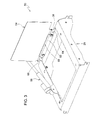
Fig. 1 , and - Fig. 3
- is a different perspective view of the detail of
Fig. 2 . - Referring to
Fig. 1 , avehicle cooling system 10 is provided for a work vehicle (not shown). Thevehicle cooling system 10 includes afirst frame 12 which supports a front orfirst heat exchanger 14, such as a vehicle radiator. Both thefirst frame 12 and thefirst heat exchanger 14 have a lower orfirst end 16 and an upper orsecond end 18 which are positioned opposite from each other. - A
cooling fan 20 is spaced apart from thefirst heat exchanger 14, and is surrounded by afan frame 22. Asecond heat exchanger 24 extends between thecooling fan 20 and thefirst end 16 of thefirst heat exchanger 14. Thesecond heat exchanger 24 is supported by asecond frame 26.Second frame 26 includes afront member 28, aleft side member 30, aright side member 32 and arear member 34. - Upper or
third heat exchanger 40 is spaced apart from thesecond heat exchanger 24 and extends between thecooling fan 20 and thesecond end 18 of thefirst heat exchanger 14. Thethird heat exchanger 40 is supported by athird frame 42 which extends between thesecond end 18 of thefirst frame 12 and an upper end of thefan frame 22. - A
pivoting baffle assembly 50 includes abase plate 52 which is fixed to a central portion offront member 28 ofsecond frame 26. Abaffle plate 54 has an inner end pivotally coupled to an upper end of thebase plate 52. Anactuator arm 56 projects from the inner end ofbaffle plate 54 and is at an angle with respect tobaffle plate 54. Thebaffle plate 54 has a pivot axis positioned adjacent to thefirst end 16 of thefirst heat exchanger 14. Thebaffle plate 54 extends into aspace 55 which is enclosed by thevehicle cooling system 10. - An actuator comprising a
linear actuator 58 has a first end orcylinder housing 60 pivotally coupled to theleft side member 30 ofsecond frame 26, and a second end orrod 62 pivotally coupled to theactuator arm 56. Thelinear actuator 58 is preferable a hydraulic cylinder. - Referring now to
Figs. 2 and3 ,flanges front member 28 ofsecond frame 26. Thebase plate 52 is attached to theflanges base plate 52 is pivotally coupled tobaffle plate 54 by ahinge 68. Theactuator arm 56 projects rearwardly from one side of thebaffle plate 54. - When the
linear actuator 58 is fully extended in a first position, thebaffle plate 54 will be adjacent to thefirst heat exchanger 14 and will reduce the amount of air flow through thefirst heat exchanger 14. When thelinear actuator 58 is fully retracted in a second position, thebaffle plate 54 will be adjacent to thesecond heat exchanger 24 and will reduce the amount of air flow through thesecond heat exchanger 24. Themovable baffle plate 54 can be electronically controlled by means of thelinear actuator 58 using sensors (not shown) to determine which of theheat exchangers
Claims (6)
- A vehicle cooling system, the vehicle cooling system (10) comprising a first heat exchanger (14) having a first end (16) and a second end (18) positioned opposite from the first end (16); a cooling fan (20) spaced apart from the first heat exchanger (14); a second heat exchanger (24) extending between the cooling fan (20) and the first end (16) of the first heat exchanger (14); a third heat exchanger (40) spaced apart from the second heat exchanger (24) and extending between the cooling fan (20) and the second end (18) of the first heat exchanger (14); a baffle plate (54) pivotally mounted to the vehicle cooling system (10), the baffle plate (54) having a pivot axis positioned adjacent to the first end (16) of the first heat exchanger (14), the baffle plate (54) being pivotal to a first position reducing air flow through the first heat exchanger (14) and to a second position reducing air flow through the second heat exchanger (24); and an actuator (58) for pivoting the baffle plate (54) about the pivot axis.
- The vehicle cooling system according to claim 1, characterized in that the baffle plate (54) extending into a space (55) which is enclosed by the vehicle cooling system (10).
- The vehicle cooling system according to claim 1 or 2, characterized in that the actuator comprises a linear actuator (58).
- The vehicle cooling system according to claims 1 to 3, characterized in that the actuator (58) comprises a hydraulic cylinder having a cylinder housing (60) pivotally coupled to a second frame (26) of the second heat exchanger (24), and having a rod (62) pivotally coupled to the baffle plate (54).
- The vehicle cooling system according to claims 1 to 4, characterized in that an actuator arm (56) projects from an inner end of the baffle plate (54), the actuator (58) being coupled to the actuator arm (56).
- The vehicle cooling system according to claim 5, characterized in that the actuator arm (56) projects at an angle with respect to the baffle plate (54).
Applications Claiming Priority (1)
| Application Number | Priority Date | Filing Date | Title |
|---|---|---|---|
| US13/967,989 US9751377B2 (en) | 2013-08-15 | 2013-08-15 | Multi-unit cooling system with dynamic baffle |
Publications (3)
| Publication Number | Publication Date |
|---|---|
| EP2837515A2 true EP2837515A2 (en) | 2015-02-18 |
| EP2837515A3 EP2837515A3 (en) | 2015-08-26 |
| EP2837515B1 EP2837515B1 (en) | 2016-09-14 |
Family
ID=51224861
Family Applications (1)
| Application Number | Title | Priority Date | Filing Date |
|---|---|---|---|
| EP14178755.6A Not-in-force EP2837515B1 (en) | 2013-08-15 | 2014-07-28 | Vehicle cooling system |
Country Status (5)
| Country | Link |
|---|---|
| US (1) | US9751377B2 (en) |
| EP (1) | EP2837515B1 (en) |
| JP (1) | JP2015037933A (en) |
| CN (1) | CN104369658B (en) |
| IN (1) | IN2014MU02272A (en) |
Cited By (1)
| Publication number | Priority date | Publication date | Assignee | Title |
|---|---|---|---|---|
| US20240240583A1 (en) * | 2021-07-30 | 2024-07-18 | Cnh Industrial America Llc | Active baffling for cooling systems |
Families Citing this family (14)
| Publication number | Priority date | Publication date | Assignee | Title |
|---|---|---|---|---|
| FR3042458B1 (en) * | 2015-10-15 | 2018-07-13 | Valeo Systemes Thermiques | Air inlet control device with remote actuator |
| CN105370374B (en) * | 2015-12-15 | 2018-02-13 | 重庆黄河摩托车有限公司 | A kind of motor tricycle cooling system |
| US10533881B2 (en) | 2016-04-10 | 2020-01-14 | Forum Us, Inc. | Airflow sensor assembly for monitored heat exchanger system |
| US10502597B2 (en) | 2016-04-10 | 2019-12-10 | Forum Us, Inc. | Monitored heat exchanger system |
| US10545002B2 (en) | 2016-04-10 | 2020-01-28 | Forum Us, Inc. | Method for monitoring a heat exchanger unit |
| US10514205B2 (en) | 2016-04-10 | 2019-12-24 | Forum Us, Inc. | Heat exchanger unit |
| US10520220B2 (en) * | 2016-04-10 | 2019-12-31 | Forum Us, Inc. | Heat exchanger unit |
| CN106515426A (en) * | 2016-08-16 | 2017-03-22 | 合肥升园汽车配件有限公司 | Radiating cooling control system of automobile air-conditioning |
| US10302374B2 (en) * | 2016-09-14 | 2019-05-28 | Mahindra Vehicle Manufacturers Limited | Baffle assembly for a charge air cooler |
| CA2969703C (en) * | 2017-04-02 | 2019-11-12 | Global Heat Transfer Ulc | Monitored heat exchanger system and related |
| US11098962B2 (en) | 2019-02-22 | 2021-08-24 | Forum Us, Inc. | Finless heat exchanger apparatus and methods |
| JP2020152194A (en) * | 2019-03-19 | 2020-09-24 | いすゞ自動車株式会社 | How to adjust the wind direction of the blower and the vehicle equipped with the blower |
| US11946667B2 (en) | 2019-06-18 | 2024-04-02 | Forum Us, Inc. | Noise suppresion vertical curtain apparatus for heat exchanger units |
| CN112196821B (en) * | 2020-09-30 | 2022-07-19 | 江苏徐工工程机械研究院有限公司 | Heat dissipation and noise cooperative matching device, optimization method and system |
Family Cites Families (15)
| Publication number | Priority date | Publication date | Assignee | Title |
|---|---|---|---|---|
| JPS6015215A (en) * | 1983-07-05 | 1985-01-25 | Diesel Kiki Co Ltd | Air conditioner for vehicle |
| JP3374266B2 (en) | 1997-04-08 | 2003-02-04 | 新キャタピラー三菱株式会社 | Cooling equipment for work machines |
| GB2336662B (en) * | 1998-04-21 | 2002-04-10 | Agco Gmbh & Co | Vehicle cooling radiator arrangement |
| JP2002356115A (en) | 2001-05-31 | 2002-12-10 | Hitachi Constr Mach Co Ltd | Cooling device for construction machine |
| US6766774B1 (en) | 2003-06-18 | 2004-07-27 | General Motors Corporation | Cooling module with axial blower and pressure regulated cross-flow fan |
| DE102004034313B4 (en) | 2004-07-15 | 2013-09-26 | Volkswagen Ag | Coolant line assembly |
| US7766111B2 (en) * | 2004-10-29 | 2010-08-03 | Daimler Trucks North America Llc | Selective closing of at least one vehicle opening at a front portion of a vehicle |
| US20070007061A1 (en) | 2005-07-06 | 2007-01-11 | Deere & Company | Plenum cooling system |
| DE102006062116A1 (en) * | 2005-12-23 | 2007-06-28 | Behr Gmbh & Co. Kg | Radiator system for a motor vehicle has two or more air-cooled radiators fitted directly alongside each other with an angle between 60degrees and 80degrees, at most 90degrees, between airflow surface and direction |
| JP4505510B2 (en) * | 2007-02-20 | 2010-07-21 | カルソニックカンセイ株式会社 | Vehicle air conditioning system |
| JP4909972B2 (en) | 2008-10-02 | 2012-04-04 | 本田技研工業株式会社 | Cooling device for vehicle engine |
| JP5199849B2 (en) * | 2008-12-05 | 2013-05-15 | 三菱重工業株式会社 | Vehicle heat exchange module and vehicle equipped with the same |
| WO2011075009A1 (en) | 2009-12-15 | 2011-06-23 | Volvo Lastvagnar Ab | Arrangement and method for optimizing the position of at least one air deflector |
| US8585064B2 (en) * | 2011-04-21 | 2013-11-19 | ET Works, LLC | Pivoting axle suspension assembly for a crop sprayer |
| JP5824961B2 (en) * | 2011-08-19 | 2015-12-02 | コベルコ建機株式会社 | Construction machine cooling system |
-
2013
- 2013-08-15 US US13/967,989 patent/US9751377B2/en not_active Expired - Fee Related
-
2014
- 2014-07-11 IN IN2272MU2014 patent/IN2014MU02272A/en unknown
- 2014-07-23 JP JP2014149474A patent/JP2015037933A/en active Pending
- 2014-07-28 EP EP14178755.6A patent/EP2837515B1/en not_active Not-in-force
- 2014-08-14 CN CN201410399799.6A patent/CN104369658B/en not_active Expired - Fee Related
Non-Patent Citations (1)
| Title |
|---|
| None |
Cited By (1)
| Publication number | Priority date | Publication date | Assignee | Title |
|---|---|---|---|---|
| US20240240583A1 (en) * | 2021-07-30 | 2024-07-18 | Cnh Industrial America Llc | Active baffling for cooling systems |
Also Published As
| Publication number | Publication date |
|---|---|
| EP2837515A3 (en) | 2015-08-26 |
| IN2014MU02272A (en) | 2015-10-09 |
| JP2015037933A (en) | 2015-02-26 |
| US9751377B2 (en) | 2017-09-05 |
| EP2837515B1 (en) | 2016-09-14 |
| CN104369658B (en) | 2019-04-12 |
| CN104369658A (en) | 2015-02-25 |
| US20150047811A1 (en) | 2015-02-19 |
Similar Documents
| Publication | Publication Date | Title |
|---|---|---|
| EP2837515B1 (en) | Vehicle cooling system | |
| EP2038527B1 (en) | Cooler arrangement for a motor vehicle | |
| CN106715176B (en) | Air-inlet grille module | |
| EP3327857A3 (en) | Thermal dissipation system of an electric vehicle | |
| DE602007010573D1 (en) | Mounting a heat exchanger | |
| US10730362B2 (en) | Vehicle radiator assemblies with coolant paths via moveable blades | |
| JP6415890B2 (en) | Work vehicle | |
| WO2007054330A3 (en) | Circulation system, mixing element | |
| ATE422189T1 (en) | SUPPORT STRUCTURE IN THE FRONT AREA OF A MOTOR VEHICLE | |
| US20170326966A1 (en) | Heat Exchanger System | |
| NO20000790L (en) | Standalone mobile radiator | |
| WO2005031902A3 (en) | Fuel cell temperature control apparatus | |
| WO2007077491A3 (en) | Tractor cooling installation | |
| US20150168031A1 (en) | Heat exchanger with thermoelectric elements | |
| BR102014004748A2 (en) | driver's cab for a truck, preferably a mechanical horse truck and truck, preferably a mechanical horse truck. | |
| JP5492355B2 (en) | Industrial vehicle fork | |
| US10352621B2 (en) | Dual axial fan with a thermal exchange component for a vehicle | |
| CN204881295U (en) | Heat sink aluminum tube | |
| JP2020082792A (en) | Bumper reinforcement and vehicle body front part structure | |
| JP6333764B2 (en) | Construction machinery | |
| CN217972460U (en) | A singly cut mechanism for fork truck | |
| Li et al. | Nested Bethe ansatz for the BN vertex model with open boundary conditions | |
| CN208963114U (en) | A kind of adjustable driver's cabin transiting vehicle | |
| WO2020054588A1 (en) | Radiator structure | |
| FR3061767B1 (en) | COLLECTOR BOX FOR THERMAL EXCHANGER, ESPECIALLY FOR MOTOR VEHICLE, HEAT EXCHANGER AND CORRESPONDING MANUFACTURING METHOD THEREFOR. |
Legal Events
| Date | Code | Title | Description |
|---|---|---|---|
| 17P | Request for examination filed |
Effective date: 20140728 |
|
| AK | Designated contracting states |
Kind code of ref document: A2 Designated state(s): AL AT BE BG CH CY CZ DE DK EE ES FI FR GB GR HR HU IE IS IT LI LT LU LV MC MK MT NL NO PL PT RO RS SE SI SK SM TR |
|
| AX | Request for extension of the european patent |
Extension state: BA ME |
|
| PUAI | Public reference made under article 153(3) epc to a published international application that has entered the european phase |
Free format text: ORIGINAL CODE: 0009012 |
|
| PUAL | Search report despatched |
Free format text: ORIGINAL CODE: 0009013 |
|
| AK | Designated contracting states |
Kind code of ref document: A3 Designated state(s): AL AT BE BG CH CY CZ DE DK EE ES FI FR GB GR HR HU IE IS IT LI LT LU LV MC MK MT NL NO PL PT RO RS SE SI SK SM TR |
|
| AX | Request for extension of the european patent |
Extension state: BA ME |
|
| RIC1 | Information provided on ipc code assigned before grant |
Ipc: B60K 11/08 20060101ALI20150721BHEP Ipc: F01P 3/18 20060101ALI20150721BHEP Ipc: B60H 1/00 20060101ALI20150721BHEP Ipc: B60K 11/04 20060101AFI20150721BHEP |
|
| R17P | Request for examination filed (corrected) |
Effective date: 20160226 |
|
| RBV | Designated contracting states (corrected) |
Designated state(s): AL AT BE BG CH CY CZ DE DK EE ES FI FR GB GR HR HU IE IS IT LI LT LU LV MC MK MT NL NO PL PT RO RS SE SI SK SM TR |
|
| GRAP | Despatch of communication of intention to grant a patent |
Free format text: ORIGINAL CODE: EPIDOSNIGR1 |
|
| RIC1 | Information provided on ipc code assigned before grant |
Ipc: B60K 11/04 20060101AFI20160324BHEP Ipc: F01P 3/18 20060101ALI20160324BHEP Ipc: B60K 11/08 20060101ALI20160324BHEP Ipc: B60H 1/00 20060101ALI20160324BHEP Ipc: F01P 7/10 20060101ALI20160324BHEP |
|
| INTG | Intention to grant announced |
Effective date: 20160411 |
|
| GRAS | Grant fee paid |
Free format text: ORIGINAL CODE: EPIDOSNIGR3 |
|
| GRAA | (expected) grant |
Free format text: ORIGINAL CODE: 0009210 |
|
| AK | Designated contracting states |
Kind code of ref document: B1 Designated state(s): AL AT BE BG CH CY CZ DE DK EE ES FI FR GB GR HR HU IE IS IT LI LT LU LV MC MK MT NL NO PL PT RO RS SE SI SK SM TR |
|
| REG | Reference to a national code |
Ref country code: GB Ref legal event code: FG4D |
|
| REG | Reference to a national code |
Ref country code: CH Ref legal event code: EP |
|
| REG | Reference to a national code |
Ref country code: IE Ref legal event code: FG4D |
|
| REG | Reference to a national code |
Ref country code: AT Ref legal event code: REF Ref document number: 828547 Country of ref document: AT Kind code of ref document: T Effective date: 20161015 |
|
| REG | Reference to a national code |
Ref country code: DE Ref legal event code: R096 Ref document number: 602014003627 Country of ref document: DE |
|
| REG | Reference to a national code |
Ref country code: LT Ref legal event code: MG4D |
|
| REG | Reference to a national code |
Ref country code: NL Ref legal event code: MP Effective date: 20160914 |
|
| PG25 | Lapsed in a contracting state [announced via postgrant information from national office to epo] |
Ref country code: NO Free format text: LAPSE BECAUSE OF FAILURE TO SUBMIT A TRANSLATION OF THE DESCRIPTION OR TO PAY THE FEE WITHIN THE PRESCRIBED TIME-LIMIT Effective date: 20161214 Ref country code: HR Free format text: LAPSE BECAUSE OF FAILURE TO SUBMIT A TRANSLATION OF THE DESCRIPTION OR TO PAY THE FEE WITHIN THE PRESCRIBED TIME-LIMIT Effective date: 20160914 Ref country code: FI Free format text: LAPSE BECAUSE OF FAILURE TO SUBMIT A TRANSLATION OF THE DESCRIPTION OR TO PAY THE FEE WITHIN THE PRESCRIBED TIME-LIMIT Effective date: 20160914 Ref country code: LT Free format text: LAPSE BECAUSE OF FAILURE TO SUBMIT A TRANSLATION OF THE DESCRIPTION OR TO PAY THE FEE WITHIN THE PRESCRIBED TIME-LIMIT Effective date: 20160914 Ref country code: RS Free format text: LAPSE BECAUSE OF FAILURE TO SUBMIT A TRANSLATION OF THE DESCRIPTION OR TO PAY THE FEE WITHIN THE PRESCRIBED TIME-LIMIT Effective date: 20160914 |
|
| REG | Reference to a national code |
Ref country code: AT Ref legal event code: MK05 Ref document number: 828547 Country of ref document: AT Kind code of ref document: T Effective date: 20160914 |
|
| PG25 | Lapsed in a contracting state [announced via postgrant information from national office to epo] |
Ref country code: LV Free format text: LAPSE BECAUSE OF FAILURE TO SUBMIT A TRANSLATION OF THE DESCRIPTION OR TO PAY THE FEE WITHIN THE PRESCRIBED TIME-LIMIT Effective date: 20160914 Ref country code: GR Free format text: LAPSE BECAUSE OF FAILURE TO SUBMIT A TRANSLATION OF THE DESCRIPTION OR TO PAY THE FEE WITHIN THE PRESCRIBED TIME-LIMIT Effective date: 20161215 Ref country code: SE Free format text: LAPSE BECAUSE OF FAILURE TO SUBMIT A TRANSLATION OF THE DESCRIPTION OR TO PAY THE FEE WITHIN THE PRESCRIBED TIME-LIMIT Effective date: 20160914 Ref country code: NL Free format text: LAPSE BECAUSE OF FAILURE TO SUBMIT A TRANSLATION OF THE DESCRIPTION OR TO PAY THE FEE WITHIN THE PRESCRIBED TIME-LIMIT Effective date: 20160914 |
|
| PG25 | Lapsed in a contracting state [announced via postgrant information from national office to epo] |
Ref country code: EE Free format text: LAPSE BECAUSE OF FAILURE TO SUBMIT A TRANSLATION OF THE DESCRIPTION OR TO PAY THE FEE WITHIN THE PRESCRIBED TIME-LIMIT Effective date: 20160914 Ref country code: RO Free format text: LAPSE BECAUSE OF FAILURE TO SUBMIT A TRANSLATION OF THE DESCRIPTION OR TO PAY THE FEE WITHIN THE PRESCRIBED TIME-LIMIT Effective date: 20160914 |
|
| PG25 | Lapsed in a contracting state [announced via postgrant information from national office to epo] |
Ref country code: CZ Free format text: LAPSE BECAUSE OF FAILURE TO SUBMIT A TRANSLATION OF THE DESCRIPTION OR TO PAY THE FEE WITHIN THE PRESCRIBED TIME-LIMIT Effective date: 20160914 Ref country code: PL Free format text: LAPSE BECAUSE OF FAILURE TO SUBMIT A TRANSLATION OF THE DESCRIPTION OR TO PAY THE FEE WITHIN THE PRESCRIBED TIME-LIMIT Effective date: 20160914 Ref country code: SK Free format text: LAPSE BECAUSE OF FAILURE TO SUBMIT A TRANSLATION OF THE DESCRIPTION OR TO PAY THE FEE WITHIN THE PRESCRIBED TIME-LIMIT Effective date: 20160914 Ref country code: SM Free format text: LAPSE BECAUSE OF FAILURE TO SUBMIT A TRANSLATION OF THE DESCRIPTION OR TO PAY THE FEE WITHIN THE PRESCRIBED TIME-LIMIT Effective date: 20160914 Ref country code: IS Free format text: LAPSE BECAUSE OF FAILURE TO SUBMIT A TRANSLATION OF THE DESCRIPTION OR TO PAY THE FEE WITHIN THE PRESCRIBED TIME-LIMIT Effective date: 20170114 Ref country code: PT Free format text: LAPSE BECAUSE OF FAILURE TO SUBMIT A TRANSLATION OF THE DESCRIPTION OR TO PAY THE FEE WITHIN THE PRESCRIBED TIME-LIMIT Effective date: 20170116 Ref country code: ES Free format text: LAPSE BECAUSE OF FAILURE TO SUBMIT A TRANSLATION OF THE DESCRIPTION OR TO PAY THE FEE WITHIN THE PRESCRIBED TIME-LIMIT Effective date: 20160914 Ref country code: BE Free format text: LAPSE BECAUSE OF FAILURE TO SUBMIT A TRANSLATION OF THE DESCRIPTION OR TO PAY THE FEE WITHIN THE PRESCRIBED TIME-LIMIT Effective date: 20160914 Ref country code: AT Free format text: LAPSE BECAUSE OF FAILURE TO SUBMIT A TRANSLATION OF THE DESCRIPTION OR TO PAY THE FEE WITHIN THE PRESCRIBED TIME-LIMIT Effective date: 20160914 Ref country code: BG Free format text: LAPSE BECAUSE OF FAILURE TO SUBMIT A TRANSLATION OF THE DESCRIPTION OR TO PAY THE FEE WITHIN THE PRESCRIBED TIME-LIMIT Effective date: 20161214 |
|
| REG | Reference to a national code |
Ref country code: DE Ref legal event code: R097 Ref document number: 602014003627 Country of ref document: DE |
|
| PG25 | Lapsed in a contracting state [announced via postgrant information from national office to epo] |
Ref country code: IT Free format text: LAPSE BECAUSE OF FAILURE TO SUBMIT A TRANSLATION OF THE DESCRIPTION OR TO PAY THE FEE WITHIN THE PRESCRIBED TIME-LIMIT Effective date: 20160914 |
|
| PLBE | No opposition filed within time limit |
Free format text: ORIGINAL CODE: 0009261 |
|
| STAA | Information on the status of an ep patent application or granted ep patent |
Free format text: STATUS: NO OPPOSITION FILED WITHIN TIME LIMIT |
|
| PG25 | Lapsed in a contracting state [announced via postgrant information from national office to epo] |
Ref country code: DK Free format text: LAPSE BECAUSE OF FAILURE TO SUBMIT A TRANSLATION OF THE DESCRIPTION OR TO PAY THE FEE WITHIN THE PRESCRIBED TIME-LIMIT Effective date: 20160914 |
|
| 26N | No opposition filed |
Effective date: 20170615 |
|
| PG25 | Lapsed in a contracting state [announced via postgrant information from national office to epo] |
Ref country code: SI Free format text: LAPSE BECAUSE OF FAILURE TO SUBMIT A TRANSLATION OF THE DESCRIPTION OR TO PAY THE FEE WITHIN THE PRESCRIBED TIME-LIMIT Effective date: 20160914 |
|
| REG | Reference to a national code |
Ref country code: CH Ref legal event code: PL |
|
| REG | Reference to a national code |
Ref country code: IE Ref legal event code: MM4A |
|
| REG | Reference to a national code |
Ref country code: FR Ref legal event code: ST Effective date: 20180330 |
|
| PG25 | Lapsed in a contracting state [announced via postgrant information from national office to epo] |
Ref country code: IE Free format text: LAPSE BECAUSE OF NON-PAYMENT OF DUE FEES Effective date: 20170728 Ref country code: LI Free format text: LAPSE BECAUSE OF NON-PAYMENT OF DUE FEES Effective date: 20170731 Ref country code: CH Free format text: LAPSE BECAUSE OF NON-PAYMENT OF DUE FEES Effective date: 20170731 |
|
| PG25 | Lapsed in a contracting state [announced via postgrant information from national office to epo] |
Ref country code: FR Free format text: LAPSE BECAUSE OF NON-PAYMENT OF DUE FEES Effective date: 20170731 |
|
| PG25 | Lapsed in a contracting state [announced via postgrant information from national office to epo] |
Ref country code: LU Free format text: LAPSE BECAUSE OF NON-PAYMENT OF DUE FEES Effective date: 20170728 |
|
| PG25 | Lapsed in a contracting state [announced via postgrant information from national office to epo] |
Ref country code: MT Free format text: LAPSE BECAUSE OF NON-PAYMENT OF DUE FEES Effective date: 20170728 |
|
| PG25 | Lapsed in a contracting state [announced via postgrant information from national office to epo] |
Ref country code: AL Free format text: LAPSE BECAUSE OF FAILURE TO SUBMIT A TRANSLATION OF THE DESCRIPTION OR TO PAY THE FEE WITHIN THE PRESCRIBED TIME-LIMIT Effective date: 20160914 |
|
| GBPC | Gb: european patent ceased through non-payment of renewal fee |
Effective date: 20180728 |
|
| PG25 | Lapsed in a contracting state [announced via postgrant information from national office to epo] |
Ref country code: GB Free format text: LAPSE BECAUSE OF NON-PAYMENT OF DUE FEES Effective date: 20180728 |
|
| PG25 | Lapsed in a contracting state [announced via postgrant information from national office to epo] |
Ref country code: MC Free format text: LAPSE BECAUSE OF FAILURE TO SUBMIT A TRANSLATION OF THE DESCRIPTION OR TO PAY THE FEE WITHIN THE PRESCRIBED TIME-LIMIT Effective date: 20160914 Ref country code: HU Free format text: LAPSE BECAUSE OF FAILURE TO SUBMIT A TRANSLATION OF THE DESCRIPTION OR TO PAY THE FEE WITHIN THE PRESCRIBED TIME-LIMIT; INVALID AB INITIO Effective date: 20140728 |
|
| PG25 | Lapsed in a contracting state [announced via postgrant information from national office to epo] |
Ref country code: CY Free format text: LAPSE BECAUSE OF FAILURE TO SUBMIT A TRANSLATION OF THE DESCRIPTION OR TO PAY THE FEE WITHIN THE PRESCRIBED TIME-LIMIT Effective date: 20160914 |
|
| PG25 | Lapsed in a contracting state [announced via postgrant information from national office to epo] |
Ref country code: MK Free format text: LAPSE BECAUSE OF FAILURE TO SUBMIT A TRANSLATION OF THE DESCRIPTION OR TO PAY THE FEE WITHIN THE PRESCRIBED TIME-LIMIT Effective date: 20160914 |
|
| PG25 | Lapsed in a contracting state [announced via postgrant information from national office to epo] |
Ref country code: TR Free format text: LAPSE BECAUSE OF FAILURE TO SUBMIT A TRANSLATION OF THE DESCRIPTION OR TO PAY THE FEE WITHIN THE PRESCRIBED TIME-LIMIT Effective date: 20160914 |
|
| PGFP | Annual fee paid to national office [announced via postgrant information from national office to epo] |
Ref country code: DE Payment date: 20200619 Year of fee payment: 7 |
|
| REG | Reference to a national code |
Ref country code: DE Ref legal event code: R119 Ref document number: 602014003627 Country of ref document: DE |
|
| PG25 | Lapsed in a contracting state [announced via postgrant information from national office to epo] |
Ref country code: DE Free format text: LAPSE BECAUSE OF NON-PAYMENT OF DUE FEES Effective date: 20220201 |