EP2836848B1 - System and method for detecting branch circuit current - Google Patents
System and method for detecting branch circuit current Download PDFInfo
- Publication number
- EP2836848B1 EP2836848B1 EP12874241.8A EP12874241A EP2836848B1 EP 2836848 B1 EP2836848 B1 EP 2836848B1 EP 12874241 A EP12874241 A EP 12874241A EP 2836848 B1 EP2836848 B1 EP 2836848B1
- Authority
- EP
- European Patent Office
- Prior art keywords
- terminal
- signal
- current sensor
- current
- coupled
- Prior art date
- Legal status (The legal status is an assumption and is not a legal conclusion. Google has not performed a legal analysis and makes no representation as to the accuracy of the status listed.)
- Active
Links
- 238000000034 method Methods 0.000 title claims description 14
- 238000005259 measurement Methods 0.000 claims description 34
- 230000004044 response Effects 0.000 claims description 12
- 238000001514 detection method Methods 0.000 claims description 10
- 238000012544 monitoring process Methods 0.000 claims description 10
- 230000007935 neutral effect Effects 0.000 description 7
- 238000010586 diagram Methods 0.000 description 6
- 239000002699 waste material Substances 0.000 description 4
- 230000009471 action Effects 0.000 description 2
- 238000003909 pattern recognition Methods 0.000 description 2
- 230000007704 transition Effects 0.000 description 2
- 230000002159 abnormal effect Effects 0.000 description 1
- 230000004075 alteration Effects 0.000 description 1
- 238000004364 calculation method Methods 0.000 description 1
- 238000010276 construction Methods 0.000 description 1
- 230000001419 dependent effect Effects 0.000 description 1
- 230000000694 effects Effects 0.000 description 1
- 238000005265 energy consumption Methods 0.000 description 1
- 230000006872 improvement Effects 0.000 description 1
- 230000007246 mechanism Effects 0.000 description 1
- 238000012986 modification Methods 0.000 description 1
- 230000004048 modification Effects 0.000 description 1
- 238000012545 processing Methods 0.000 description 1
Images

Classifications
-
- G—PHYSICS
- G01—MEASURING; TESTING
- G01R—MEASURING ELECTRIC VARIABLES; MEASURING MAGNETIC VARIABLES
- G01R31/00—Arrangements for testing electric properties; Arrangements for locating electric faults; Arrangements for electrical testing characterised by what is being tested not provided for elsewhere
- G01R31/50—Testing of electric apparatus, lines, cables or components for short-circuits, continuity, leakage current or incorrect line connections
- G01R31/54—Testing for continuity
-
- G—PHYSICS
- G01—MEASURING; TESTING
- G01R—MEASURING ELECTRIC VARIABLES; MEASURING MAGNETIC VARIABLES
- G01R19/00—Arrangements for measuring currents or voltages or for indicating presence or sign thereof
- G01R19/0092—Arrangements for measuring currents or voltages or for indicating presence or sign thereof measuring current only
-
- G—PHYSICS
- G01—MEASURING; TESTING
- G01R—MEASURING ELECTRIC VARIABLES; MEASURING MAGNETIC VARIABLES
- G01R31/00—Arrangements for testing electric properties; Arrangements for locating electric faults; Arrangements for electrical testing characterised by what is being tested not provided for elsewhere
- G01R31/28—Testing of electronic circuits, e.g. by signal tracer
- G01R31/282—Testing of electronic circuits specially adapted for particular applications not provided for elsewhere
- G01R31/2829—Testing of circuits in sensor or actuator systems
-
- G—PHYSICS
- G01—MEASURING; TESTING
- G01R—MEASURING ELECTRIC VARIABLES; MEASURING MAGNETIC VARIABLES
- G01R31/00—Arrangements for testing electric properties; Arrangements for locating electric faults; Arrangements for electrical testing characterised by what is being tested not provided for elsewhere
- G01R31/50—Testing of electric apparatus, lines, cables or components for short-circuits, continuity, leakage current or incorrect line connections
- G01R31/52—Testing for short-circuits, leakage current or ground faults
Definitions
- At least one example in accordance with the present invention relates generally to systems and methods for detecting branch circuit current, and at least one example is directed to detecting the presence of a current sensor within a load center.
- a load center or panelboard is a component of an electrical supply system which divides an electrical power feed from a power line into different subsidiary circuit branches. Each subsidiary circuit branch may be connected to a different load. Thus, by dividing the electrical power feed into subsidiary circuit branches, the load center may allow a user to individually control and monitor the current, power and energy usage of each load.
- CT Current Transformers
- a CT may be used to measure current in a branch by producing a reduced current signal, proportionate to the current in the branch, which may be further manipulated and measured.
- a CT coupled to a branch of a load center may produce a reduced current AC measurement signal, proportionate to the magnitude of AC current in the branch.
- the reduced current AC measurement signal may then either be measured directly or converted to a digital signal and then extrapolated. Based on the signal received, the level of current in the subsidiary branch may be determined.
- Documents CN102122810 , WO2012/017638 and US2010/235122 show examples of system monitors for load centers according to prior art.
- aspects in accord with the present invention are directed to a system monitor for a load center according to claim 1 and a method for monitoring current in a load center according to claim 6.
- Embodiments of the invention are not limited to the details of construction and the arrangement of components set forth in the following description or illustrated in the drawings. Embodiments of the invention are capable of being practiced or of being carried out in various ways. Also, the phraseology and terminology used herein is for the purpose of description and should not be regarded as limiting. The use of "including,” “comprising,” or “having,” “containing”, “involving”, and variations thereof herein, is meant to encompass the items listed thereafter and equivalents thereof as well as additional items.
- CT's may be utilized with a load center of an electrical supply system to monitor circuit branches and assist in providing efficient energy management.
- CT's may be coupled to circuit branches inside or outside of a load center and provide measurement signals (in proportion to the current in the circuit branches) to terminals of a main controller and its measuring unit.
- the controller may also receive false measurement signals at the terminal in relation to the circuit branch. For example, once the terminal is disconnected from a CT, the controller may still receive false measurement signals that the controller incorrectly associates with the circuit branch. These signals may be abnormally low or high and, absent identification by the controller that the CT is disconnected from the terminal, these abnormally low or high signals may incorrectly identify, to the controller, the level of power being provided by the circuit branch to a load.
- controllers may utilize a separate CT detection subsystem to identify when a CT is coupled to a controller.
- detection subsystems typically utilize a voltage divider to identify when a CT is coupled to a controller.
- a first resistor of the voltage divider may be located in the CT and a second resistor of the voltage divider may be located within the controller.
- the voltage divider comprised of the pair of resistors, provides a voltage to the controller which identifies that the CT is connected to the controller. Absent the appropriate voltage being provided by the voltage divider, the controller identifies that the CT is not connected to the controller.
- CT detection subsystems have multiple drawbacks.
- Current through the voltage divider of the CT detection subsystem wastes valuable power.
- the CT detection subsystem may only be turned on at predefined intervals (e.g., every fifteen minutes) rather than updated continuously. Such intervals may not allow a controller to quickly identify a disconnected or newly connected CT. By only checking a CT detection subsystem at predefined, relatively long, intervals, it is likely that the controller will still waste too much energy and/or receive skewed measurements prior to the disconnected, or new, CT being identified.
- At least some embodiments herein provide a system and method for quickly detecting current sensor connectivity based on a pattern recognition of signals at a terminal which normally receives output signals from a current sensor. Utilizing pattern recognition on the signals at the terminal itself allows the controller to save power, while still detecting sensor status in a timely manner.
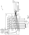
- FIG. 1 is a circuit diagram of a load center 100 in accordance with aspects of one embodiment of the present invention.
- the load center 100 includes a housing 101. Within the housing 101, the load center 100 includes an input power line 104, a plurality of input power line circuit branches 102, a plurality of neutral line circuit branches 106, and a neutral line 108.
- the input power line 104 and the neutral line 108 are configured to be coupled to an external power source (e.g., a utility power system).
- Each one of the plurality of input power line circuit branches 102 is coupled between the input power line 104 and an external load 112 (e.g., an appliance, a power outlet, a light etc.).
- Each one of the plurality of neutral line circuit branches 106 is coupled between the neutral line 108 and an external load 112.
- the input power line 104 includes a circuit breaker 113 coupled between the external power source and the input power line 104 and the neutral line 108 includes a circuit breaker 113 coupled between the external power source and the neutral line 108.
- each one of the plurality of circuit branches 102 includes a circuit breaker 115 coupled between the input power line 104 and an external load 112.
- the current rating of each of the circuit breakers 113, 115 may be configured based on the power required by the external load 112 to which the circuit breakers 113, 115 associated circuit branch 102 is coupled.
- the load center 100 also includes a plurality of Current Transformers (CT) 114 and a plurality of sensor circuits 120.
- CT Current Transformers
- Each one of the plurality of CT's 114 is coupled to at least one of the plurality of circuit branches 102.
- a CT 114 may also be coupled to the input power line 104.
- each CT 114 encompasses a corresponding circuit branch 102 or input power line 104.
- Each one of the plurality of CT's is also coupled to a corresponding sensor circuit 120.
- Each sensor circuit 120 is coupled to a terminal 127 of a CT concentrator 124 via a cable 122.
- the CT concentrator 124 is located external the housing 101; however, in other embodiments, the CT concentrator 124 is located within the housing 101.
- the CT concentrator 124 includes a plurality of terminals 127, a power module 126 and wireless radio module and antenna 128.
- the plurality of terminals 127 are RJ-11 connectors; however, in other embodiments, any other appropriate connector may be utilized.
- the power module 126 is a battery pack configured to provide DC power to the CT concentrator 124; however, in other embodiments, the power module receives AC power from the input power line 104 (e.g. via at least one branch circuit 102), converts the AC power to DC power and provides the DC power to the CT concentrator 124.
- AC power is provided from an external source (e.g., a utility power system) to the input power line 104.
- AC power from the input power line 104 is provided to each one of the external loads 112, via the loads associated circuit branch 102.
- the circuit breakers 113 are configured to automatically open and prevent current in the input power line 104 if an overload or short circuit is detected on the input power line 104.
- the circuit breakers 115 are configured to automatically open and prevent current in a circuit branch 102 if an overload or short circuit is detected in the circuit branch 102.
- AC current passing through a circuit branch 102 or input power line 104 induces a proportionate AC measurement signal in its associated CT 114 which encompasses the circuit branch 102 or input line 104.
- a CT 114 is coupled to multiple circuit branches 102
- an AC measurement signal proportionate to the combined current in the multiple circuit branches is induced in the CT 114 which encompasses the multiple circuit branches.
- the sensor circuit 120 coupled to the CT 114 transmits the proportionate AC measurement signals from the CT 114 to a terminal 127 of the CT concentrator 124 via its corresponding cable 122.
- the CT concentrator 124 receives the AC measurement signals from the sensor circuits 120.
- the CT concentrator 124 may display the current information to a user; analyze the received current information, use the current information in additional power calculations related to the associated circuit branches, transmit the information to an external client (e.g. a web server, in-home display, internet gateway, etc.) via the wireless radio module 128 or a hardwired connection, or any other appropriate action.
- an external client e.g. a web server, in-home display, internet gateway, etc.
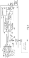
- FIG. 2 is a block diagram of a CT concentrator 124 in accordance with aspects of the present invention.
- the CT concentrator 124 has a plurality of terminals 127 which are configured to be connected to a plurality of sensor circuits 120 and CT's 114 via cables 122.
- the CT concentrator 124 includes a power module 126 and in one embodiment, the power module 126 is a battery pack.
- the battery pack includes 4 AA sized batteries connected in series and a DC interface 214.
- the power module 126 is modular and may be removed from the CT concentrator 124.
- the CT concentrator 124 includes a DC interface 216 configured to be coupled to the DC interface 214 of the battery pack 126.
- the DC interface 216 of the CT concentrator 124 is coupled to a power management module 224.
- the power management module 224 is coupled to a microcontroller 228.
- the microcontroller is coupled to the plurality of terminals 127.
- the microcontroller 228 includes an Analog to Digital Converter (ADC) which is configured to receive the analog current measurement signals from the terminals 127 (i.e. signals received at the terminals from the sensor circuits 120) and convert the analog signals to digital signals for further processing by the microcontroller 228.
- the CT concentrator 124 also includes a Real Time Clock (RTC) 229 coupled to the microcontroller 228.
- RTC Real Time Clock
- the CT concentrator 124 also includes a non-volatile memory module 232 coupled to the microcontroller 228.
- the non-volatile memory module 232 includes Electrically Erasable Programmable Read-Only Memory (EEPROM); however, in other embodiments, the non-volatile memory module 232 may include any type of non-volatile memory (e.g., such as serial Flash memory).
- EEPROM Electrically Erasable Programmable Read-Only Memory
- the CT concentrator 124 also includes a user interface 234 coupled to the microcontroller 228.
- the user interface may include any type of controls which allows a user to interface with the CT concentrator 124. (e.g., such controls include switches, buttons, LED's etc.).
- the CT concentrator 124 also includes a USB port 236 and a serial port 238.
- the CT concentrator 124 also includes the wireless radio module and antenna 128 coupled to the microcontroller 228.
- the wireless radio module 128 is a ZigBee radio; however, in other embodiments, the wireless radio module 128 may be configured using a different wireless standard.
- the wireless radio module and antenna 128 is also coupled to an On/Off switch 242 and a serial memory module 244.
- the battery pack 127 provides DC power to the CT concentrator 124 via the DC interface 214 and the DC interface 216.
- the power management module 224 receives the DC power from the first DC interface 216 and provides appropriate DC power to components of the CT concentrator 124 (e.g., the microcontroller 228).
- the microcontroller 228 Upon being powered, the microcontroller 228 monitors signals at the terminals 127 and based on the signals at each terminal, the microcontroller 228 determines whether a CT 114 (and sensor circuit 120) is coupled to each terminal.
- the microcontroller 228 compares the signals at each terminal to a pre-defined fixed signal envelope.
- the signal envelope is defined about a zero-crossing value at which analog measurement signals (received at the terminal 127 from a CT 114) would pass through under normal operating conditions (i.e. when a CT 114 is coupled to a terminal 127 and providing measurement signals to the terminal 127).
- the fixed signal envelope defines a first fixed signal level that is greater than the zero-crossing value and a second fixed signal level that is less than the zero-crossing value.
- the signal envelope is defined to be wide enough (i.e. the first and second fixed signal levels are far enough apart) that noise does not typically cause false tripping (i.e. the noise does not cause the signal to pass outside the signal envelope).
- the signal envelope is defined to be narrow enough (i.e. the first and second fixed signal levels are close enough) so that the connection of a sensor can be detected under a wide range of conditions and tolerances.
- the signals at the terminals 127 are compared to the signal envelope at a relatively fast rate (e.g. every 15 seconds). By comparing the signals to the signal envelope at a relatively fast rate, the microcontroller 228 is able to quickly determine, based on the signals at a terminal 127, whether the terminal 127 is connected to a CT 114.
- the microcontroller 228 If a signal at a terminal 127 passes outside of the signal envelope (i.e. is greater than the first fixed signal level or less than the second fixed signal level), the microcontroller 228 starts a countdown timer. If the signal received at the terminal passes back within the signal envelope (e.g. is less than the first fixed signal level and greater than the second fixed signal level), the microcontroller 228 resets the countdown timer. If the countdown timer expires prior to being reset, the microcontroller 228 determines, because the received signal has been outside of the signal envelope longer than would be expected for an analog measurement signal received from a CT 114 connected to the terminal 127, that the terminal is not connected to a CT 114. According to one embodiment, the value of the timer is defined so that a worst case signal frequency and amplitude is accounted for without false tripping.
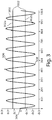
- FIG. 3 is a graph illustrating a measurement signal 300 output by a CT 114 (and received by the microcontroller 228 via a terminal 127) that is connected to a terminal 127 and to an associated circuit branch 102 that is providing power to a load 112.
- the measurement signal 300 is proportionate to current in the associated circuit branch 102.
- the graph of FIG. 3 also illustrates a fixed signal envelope 302 about the zero-crossing value 304 at which the received analog measurement signal 300 would pass through under normal operating conditions (i.e. when a CT 114 is coupled to a terminal 127).
- the fixed signal envelope includes a first fixed signal level 302a greater than the zero-crossing value and a second fixed signal level 302b less than the zero-crossing value.
- the measurement signal 300 is substantially within the signal envelope 302 and only portions of the measurement signal 300 near the peaks 306 and troughs 308 extend outside of the signal envelope 302 (i.e. are greater than the first fixed signal level 302a or less than the second fixed signal level 302b). However, as the measurement signal 300 passes back to within the signal envelope 302 (e.g. is less than the first fixed signal level 302a and greater than the second fixed signal level 302b), the microcontroller's 228 countdown timer (which was started once the signal 300 extended outside of the signal envelope 302) is reset and not allowed to expire. Therefore, upon receiving such a signal 300 as illustrated in FIG. 3 at a terminal 127, the microcontroller 228 identifies that the terminal 127 corresponding to the received signal 300 is coupled to a CT 114.
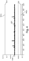
- FIG. 4 is a graph illustrating a measurement signal 400 output by a CT 114 (and received by the microcontroller 228 via a terminal 127) that is connected to a terminal 127 and to an associated circuit branch 102 that is not providing power to a load 112.
- the graph of FIG. 4 also illustrates the fixed signal envelope 302 (having the first fixed signal level 302a and the second fixed signal level 302b) about the zero-crossing value 304 at which the received analog measurement signal 400 would pass through under normal operating conditions (i.e. when a CT 114 is coupled to a terminal 127).
- the measurement signal 400 which is proportionate to current in the associated circuit branch 102, is substantially zero as the associated circuit branch 102 is not currently powering a load.
- the measurement signal 400 falls entirely within the signal envelope 302 (i.e. is less than the first fixed signal level 302a and greater than the second fixed signal level 302b).
- the microcontroller's 228 countdown timer is not started and hence, does not expire. Therefore, upon receiving such a signal 400 as illustrated in FIG. 4 at a terminal 127, the microcontroller 228 identifies that the terminal 127 corresponding to the received signal 400 is coupled to a CT 114.
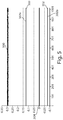
- FIG. 5 is a graph illustrating a signal 500 at a terminal 127 that indicates to the microcontroller 228 that the terminal 127 is not connected to a CT 114.
- the graph of FIG. 5 also illustrates the fixed signal envelope 302 (having the first fixed signal level 302a and the second fixed signal level 302b) about the zero-crossing value 304 at which a received analog measurement signal 500 would pass through under normal operating conditions (i.e. when a CT 114 is coupled to a terminal 127).
- the signal 500 has an abnormal significant DC offset (which is not present when a terminal 127 is receiving appropriate measurement signals from a CT 114) and is entirely outside of the signal envelope 302 (i.e. entirely greater than the first fixed signal level 302a).
- a resistor in the CT 114 typically connects the ADC input of the microcontroller 228 to a DC bias voltage in the middle of the ADC's voltage range (the level of the DC bias is interpreted by the microcontroller as the zero-crossing value 304).
- the voltage signal e.g. signal 300
- the countdown timer of the microcontroller 228 Upon receiving a signal outside of the envelope 302 (e.g. high signal 500), the countdown timer of the microcontroller 228 starts and as the signal 500 does not pass back within the signal envelope 302 (i.e. less than the first fixed signal level 302a), the timer expires. Upon expiration of the timer, the microcontroller 228 identifies that the terminal 127 associated with the signal 500 is not actually connected to a CT 114.
- a signal outside of the envelope 302 e.g. high signal 500
- the microcontroller 228 By monitoring the actual signals at the terminals 127, which normally receive measurement signals from CT's 114, the microcontroller 228 is able to identify which terminals 127 are actually coupled to CT's 114, absent the need for a separate subsystem.
- the microcontroller 228 may take additional appropriate action with regards to the terminal 127. For example, in one embodiment, the microcontroller 228 activates a standard separate CT detection subsystem (as described above) to confirm that the terminal 127 is disconnected from a CT 114. In another embodiment, in an effort to save power, the microcontroller 228 stops monitoring the signals received from the CT 114 at the terminal 127 until a standard CT detection subsystem identifies that a new CT 114 has been connected to the terminal 127.
- FIG. 6 is a state diagram 600 of a method for detecting the presence of a current sensor (e.g. a CT 114) in accordance with aspects of the present invention.
- a current sensor e.g. a CT 114
- the microcontroller 228 is powered and monitors signals at a terminal 127 to determine whether the terminal 127 is connected to a CT 114.
- the microcontroller 228 In response to a determination 604 that the terminal 127 is still connected to a CT 114 (e.g. because the signals received at the terminal 127 are within the fixed signal envelope), the microcontroller 228 remains in state 602.
- the microcontroller 228 transitions to state 608.
- the microcontroller 228 In response to a determination 612 that the terminal 127 is still disconnected from a CT 114 (e.g. because the signals received at the terminal 127 are outside of the fixed signal envelope for longer than a predetermined amount of time), the microcontroller 228 remains in state 610.
- the microcontroller 228 transitions to state 608.
- the microcontroller 228 activates a standard sensing mechanism (e.g. a standard CT detection subsystem as described above) to confirm the connection status of the terminal 127.
- a standard sensing mechanism e.g. a standard CT detection subsystem as described above
- the microcontroller monitors terminals 127 to determine whether the terminals are connected to CT's; however, in other embodiments, the microcontroller may monitor the terminals 127 to determine whether the terminals are connected to any other type of current sensor.
- a terminal 127 disconnected from a CT 114 results in a high DC offset signal being provided to the microcontroller 228; however, in other embodiments, any other type of signal, outside of the fixed signal envelope for a predetermined amount of time, may signify to the microcontroller 228 that the terminal 127 is disconnected from the CT 114.
- the microcontroller 228 is able to quickly identify which terminals 127 are actually coupled to CT's 114, absent a separate subsystem (e.g., including a voltage divider as described above) which may waste power.
- a separate subsystem e.g., including a voltage divider as described above
Description
- At least one example in accordance with the present invention relates generally to systems and methods for detecting branch circuit current, and at least one example is directed to detecting the presence of a current sensor within a load center.
- A load center or panelboard is a component of an electrical supply system which divides an electrical power feed from a power line into different subsidiary circuit branches. Each subsidiary circuit branch may be connected to a different load. Thus, by dividing the electrical power feed into subsidiary circuit branches, the load center may allow a user to individually control and monitor the current, power and energy usage of each load.
- Current sensors are commonly used to monitor activity of a load center. For example, Current Transformers (CT) are commonly used to monitor current, power and/or energy consumption in a subsidiary or main branch of a load center. A CT may be used to measure current in a branch by producing a reduced current signal, proportionate to the current in the branch, which may be further manipulated and measured. For example, a CT coupled to a branch of a load center may produce a reduced current AC measurement signal, proportionate to the magnitude of AC current in the branch. The reduced current AC measurement signal may then either be measured directly or converted to a digital signal and then extrapolated. Based on the signal received, the level of current in the subsidiary branch may be determined. Documents
CN102122810 ,WO2012/017638 andUS2010/235122 show examples of system monitors for load centers according to prior art. - Aspects in accord with the present invention are directed to a system monitor for a load center according to
claim 1 and a method for monitoring current in a load center according toclaim 6. - Further embodiments are described in the dependent claims.
- The accompanying drawings are not intended to be drawn to scale. In the drawings, each identical or nearly identical component that is illustrated in various FIGs. is represented by a like numeral. For purposes of clarity, not every component may be labeled in every drawing. In the drawings:
-
FIG. 1 is a circuit diagram of a load center in accordance with aspects of the present invention; -
FIG. 2 is a block diagram of a concentrator in accordance with aspects of the present invention; -
FIG. 3 is a graph illustrating a signal at a terminal of a concentrator corresponding to a current sensor that is connected to the terminal and to a circuit branch which is providing power to a load in accordance with aspects of the present invention; -
FIG. 4 is a graph illustrating a signal at a terminal of a concentrator corresponding to a current sensor that is connected to the terminal and to a circuit branch which is not providing power to a load in accordance with aspects of the present invention; -
FIG. 5 is a graph illustrating a signal at a terminal of a concentrator corresponding to the terminal being disconnected from a current sensor in accordance with aspects of the present invention; and -
FIG. 6 is a state diagram of a method for detecting the presence of a current sensor in accordance with aspects of the present invention. - Embodiments of the invention are not limited to the details of construction and the arrangement of components set forth in the following description or illustrated in the drawings. Embodiments of the invention are capable of being practiced or of being carried out in various ways. Also, the phraseology and terminology used herein is for the purpose of description and should not be regarded as limiting. The use of "including," "comprising," or "having," "containing", "involving", and variations thereof herein, is meant to encompass the items listed thereafter and equivalents thereof as well as additional items.
- As discussed above, CT's may be utilized with a load center of an electrical supply system to monitor circuit branches and assist in providing efficient energy management. For instance, CT's may be coupled to circuit branches inside or outside of a load center and provide measurement signals (in proportion to the current in the circuit branches) to terminals of a main controller and its measuring unit.
- Problems may arise in accurately monitoring a circuit branch when a CT coupled to the circuit branch becomes disconnected from the main controller and the controller is unaware that the CT has been disconnected. By monitoring a terminal which is disconnected from a CT, as if the terminal was connected to a CT, the controller wastes energy in monitoring the terminal. Where the controller is battery powered, this could be a relatively large problem.
- In addition, the controller may also receive false measurement signals at the terminal in relation to the circuit branch. For example, once the terminal is disconnected from a CT, the controller may still receive false measurement signals that the controller incorrectly associates with the circuit branch. These signals may be abnormally low or high and, absent identification by the controller that the CT is disconnected from the terminal, these abnormally low or high signals may incorrectly identify, to the controller, the level of power being provided by the circuit branch to a load.
- Conventional controllers may utilize a separate CT detection subsystem to identify when a CT is coupled to a controller. Such detection subsystems typically utilize a voltage divider to identify when a CT is coupled to a controller. For example, a first resistor of the voltage divider may be located in the CT and a second resistor of the voltage divider may be located within the controller. When the CT and controller are coupled together, the voltage divider, comprised of the pair of resistors, provides a voltage to the controller which identifies that the CT is connected to the controller. Absent the appropriate voltage being provided by the voltage divider, the controller identifies that the CT is not connected to the controller.
- However, such CT detection subsystems have multiple drawbacks. Current through the voltage divider of the CT detection subsystem wastes valuable power. In addition, to preserve power, the CT detection subsystem may only be turned on at predefined intervals (e.g., every fifteen minutes) rather than updated continuously. Such intervals may not allow a controller to quickly identify a disconnected or newly connected CT. By only checking a CT detection subsystem at predefined, relatively long, intervals, it is likely that the controller will still waste too much energy and/or receive skewed measurements prior to the disconnected, or new, CT being identified.
- Therefore, at least some embodiments herein provide a system and method for quickly detecting current sensor connectivity based on a pattern recognition of signals at a terminal which normally receives output signals from a current sensor. Utilizing pattern recognition on the signals at the terminal itself allows the controller to save power, while still detecting sensor status in a timely manner.
-
FIG. 1 is a circuit diagram of aload center 100 in accordance with aspects of one embodiment of the present invention. Theload center 100 includes ahousing 101. Within thehousing 101, theload center 100 includes aninput power line 104, a plurality of input powerline circuit branches 102, a plurality of neutralline circuit branches 106, and aneutral line 108. Theinput power line 104 and theneutral line 108 are configured to be coupled to an external power source (e.g., a utility power system). Each one of the plurality of input powerline circuit branches 102 is coupled between theinput power line 104 and an external load 112 (e.g., an appliance, a power outlet, a light etc.). Each one of the plurality of neutralline circuit branches 106 is coupled between theneutral line 108 and anexternal load 112. - According to one embodiment, the
input power line 104 includes acircuit breaker 113 coupled between the external power source and theinput power line 104 and theneutral line 108 includes acircuit breaker 113 coupled between the external power source and theneutral line 108. According to another embodiment, each one of the plurality ofcircuit branches 102 includes acircuit breaker 115 coupled between theinput power line 104 and anexternal load 112. In one embodiment, the current rating of each of thecircuit breakers external load 112 to which thecircuit breakers circuit branch 102 is coupled. - Within the
housing 101, theload center 100 also includes a plurality of Current Transformers (CT) 114 and a plurality ofsensor circuits 120. Each one of the plurality of CT's 114 is coupled to at least one of the plurality ofcircuit branches 102. According to one embodiment, aCT 114 may also be coupled to theinput power line 104. According to one embodiment, eachCT 114 encompasses acorresponding circuit branch 102 orinput power line 104. Each one of the plurality of CT's is also coupled to acorresponding sensor circuit 120. Eachsensor circuit 120 is coupled to aterminal 127 of aCT concentrator 124 via acable 122. According to one embodiment, theCT concentrator 124 is located external thehousing 101; however, in other embodiments, theCT concentrator 124 is located within thehousing 101. - The CT concentrator 124 includes a plurality of
terminals 127, apower module 126 and wireless radio module andantenna 128. According to one embodiment, the plurality ofterminals 127 are RJ-11 connectors; however, in other embodiments, any other appropriate connector may be utilized. According to one embodiment, thepower module 126 is a battery pack configured to provide DC power to theCT concentrator 124; however, in other embodiments, the power module receives AC power from the input power line 104 (e.g. via at least one branch circuit 102), converts the AC power to DC power and provides the DC power to theCT concentrator 124. - AC power is provided from an external source (e.g., a utility power system) to the
input power line 104. AC power from theinput power line 104 is provided to each one of theexternal loads 112, via the loads associatedcircuit branch 102. Thecircuit breakers 113 are configured to automatically open and prevent current in theinput power line 104 if an overload or short circuit is detected on theinput power line 104. Thecircuit breakers 115 are configured to automatically open and prevent current in acircuit branch 102 if an overload or short circuit is detected in thecircuit branch 102. - AC current passing through a
circuit branch 102 orinput power line 104 induces a proportionate AC measurement signal in its associatedCT 114 which encompasses thecircuit branch 102 orinput line 104. According to one embodiment, where aCT 114 is coupled tomultiple circuit branches 102, an AC measurement signal proportionate to the combined current in the multiple circuit branches is induced in theCT 114 which encompasses the multiple circuit branches. - The
sensor circuit 120 coupled to theCT 114 transmits the proportionate AC measurement signals from theCT 114 to aterminal 127 of the CT concentrator 124 via itscorresponding cable 122. The CT concentrator 124 receives the AC measurement signals from thesensor circuits 120. Upon receiving the current measurement signals from thesensor circuits 120, theCT concentrator 124 may display the current information to a user; analyze the received current information, use the current information in additional power calculations related to the associated circuit branches, transmit the information to an external client (e.g. a web server, in-home display, internet gateway, etc.) via thewireless radio module 128 or a hardwired connection, or any other appropriate action. -
FIG. 2 is a block diagram of aCT concentrator 124 in accordance with aspects of the present invention. As discussed above, theCT concentrator 124 has a plurality ofterminals 127 which are configured to be connected to a plurality ofsensor circuits 120 and CT's 114 viacables 122. As also discussed above, theCT concentrator 124 includes apower module 126 and in one embodiment, thepower module 126 is a battery pack. According to one embodiment, the battery pack includes 4 AA sized batteries connected in series and aDC interface 214. In one embodiment, thepower module 126 is modular and may be removed from theCT concentrator 124. - According to one embodiment, the
CT concentrator 124 includes aDC interface 216 configured to be coupled to theDC interface 214 of thebattery pack 126. TheDC interface 216 of theCT concentrator 124 is coupled to apower management module 224. Thepower management module 224 is coupled to amicrocontroller 228. The microcontroller is coupled to the plurality ofterminals 127. According to one embodiment, themicrocontroller 228 includes an Analog to Digital Converter (ADC) which is configured to receive the analog current measurement signals from the terminals 127 (i.e. signals received at the terminals from the sensor circuits 120) and convert the analog signals to digital signals for further processing by themicrocontroller 228. In one embodiment, the CT concentrator 124 also includes a Real Time Clock (RTC) 229 coupled to themicrocontroller 228. - The CT concentrator 124 also includes a
non-volatile memory module 232 coupled to themicrocontroller 228. In one embodiment, thenon-volatile memory module 232 includes Electrically Erasable Programmable Read-Only Memory (EEPROM); however, in other embodiments, thenon-volatile memory module 232 may include any type of non-volatile memory (e.g., such as serial Flash memory). - The CT concentrator 124 also includes a
user interface 234 coupled to themicrocontroller 228. In some embodiments, the user interface may include any type of controls which allows a user to interface with theCT concentrator 124. (e.g., such controls include switches, buttons, LED's etc.). According to one embodiment, the CT concentrator 124 also includes aUSB port 236 and aserial port 238. - The CT concentrator 124 also includes the wireless radio module and
antenna 128 coupled to themicrocontroller 228. In one embodiment, thewireless radio module 128 is a ZigBee radio; however, in other embodiments, thewireless radio module 128 may be configured using a different wireless standard. According to one embodiment, the wireless radio module andantenna 128 is also coupled to an On/Off switch 242 and aserial memory module 244. - The
battery pack 127 provides DC power to the CT concentrator 124 via theDC interface 214 and theDC interface 216. Thepower management module 224 receives the DC power from thefirst DC interface 216 and provides appropriate DC power to components of the CT concentrator 124 (e.g., the microcontroller 228). - Upon being powered, the
microcontroller 228 monitors signals at theterminals 127 and based on the signals at each terminal, themicrocontroller 228 determines whether a CT 114 (and sensor circuit 120) is coupled to each terminal. - The
microcontroller 228 compares the signals at each terminal to a pre-defined fixed signal envelope. According to one embodiment, the signal envelope is defined about a zero-crossing value at which analog measurement signals (received at the terminal 127 from a CT 114) would pass through under normal operating conditions (i.e. when aCT 114 is coupled to a terminal 127 and providing measurement signals to the terminal 127). For example, the fixed signal envelope defines a first fixed signal level that is greater than the zero-crossing value and a second fixed signal level that is less than the zero-crossing value. - According to one embodiment, the signal envelope is defined to be wide enough (i.e. the first and second fixed signal levels are far enough apart) that noise does not typically cause false tripping (i.e. the noise does not cause the signal to pass outside the signal envelope). According to another embodiment, the signal envelope is defined to be narrow enough (i.e. the first and second fixed signal levels are close enough) so that the connection of a sensor can be detected under a wide range of conditions and tolerances.
- In one embodiment, the signals at the
terminals 127 are compared to the signal envelope at a relatively fast rate (e.g. every 15 seconds). By comparing the signals to the signal envelope at a relatively fast rate, themicrocontroller 228 is able to quickly determine, based on the signals at a terminal 127, whether the terminal 127 is connected to aCT 114. - If a signal at a terminal 127 passes outside of the signal envelope (i.e. is greater than the first fixed signal level or less than the second fixed signal level), the
microcontroller 228 starts a countdown timer. If the signal received at the terminal passes back within the signal envelope (e.g. is less than the first fixed signal level and greater than the second fixed signal level), themicrocontroller 228 resets the countdown timer. If the countdown timer expires prior to being reset, themicrocontroller 228 determines, because the received signal has been outside of the signal envelope longer than would be expected for an analog measurement signal received from aCT 114 connected to the terminal 127, that the terminal is not connected to aCT 114. According to one embodiment, the value of the timer is defined so that a worst case signal frequency and amplitude is accounted for without false tripping. - For example,
FIG. 3 is a graph illustrating ameasurement signal 300 output by a CT 114 (and received by themicrocontroller 228 via a terminal 127) that is connected to a terminal 127 and to an associatedcircuit branch 102 that is providing power to aload 112. Themeasurement signal 300 is proportionate to current in the associatedcircuit branch 102. The graph ofFIG. 3 also illustrates a fixedsignal envelope 302 about the zero-crossing value 304 at which the receivedanalog measurement signal 300 would pass through under normal operating conditions (i.e. when aCT 114 is coupled to a terminal 127). The fixed signal envelope includes a first fixedsignal level 302a greater than the zero-crossing value and a second fixedsignal level 302b less than the zero-crossing value. - The
measurement signal 300 is substantially within thesignal envelope 302 and only portions of themeasurement signal 300 near thepeaks 306 andtroughs 308 extend outside of the signal envelope 302 (i.e. are greater than the first fixedsignal level 302a or less than the second fixedsignal level 302b). However, as themeasurement signal 300 passes back to within the signal envelope 302 (e.g. is less than the first fixedsignal level 302a and greater than the second fixedsignal level 302b), the microcontroller's 228 countdown timer (which was started once thesignal 300 extended outside of the signal envelope 302) is reset and not allowed to expire. Therefore, upon receiving such asignal 300 as illustrated inFIG. 3 at a terminal 127, themicrocontroller 228 identifies that the terminal 127 corresponding to the receivedsignal 300 is coupled to aCT 114. -
FIG. 4 is a graph illustrating ameasurement signal 400 output by a CT 114 (and received by themicrocontroller 228 via a terminal 127) that is connected to a terminal 127 and to an associatedcircuit branch 102 that is not providing power to aload 112. The graph ofFIG. 4 also illustrates the fixed signal envelope 302 (having the first fixedsignal level 302a and the second fixedsignal level 302b) about the zero-crossing value 304 at which the receivedanalog measurement signal 400 would pass through under normal operating conditions (i.e. when aCT 114 is coupled to a terminal 127). Themeasurement signal 400, which is proportionate to current in the associatedcircuit branch 102, is substantially zero as the associatedcircuit branch 102 is not currently powering a load. However, themeasurement signal 400 falls entirely within the signal envelope 302 (i.e. is less than the first fixedsignal level 302a and greater than the second fixedsignal level 302b). The microcontroller's 228 countdown timer is not started and hence, does not expire. Therefore, upon receiving such asignal 400 as illustrated inFIG. 4 at a terminal 127, themicrocontroller 228 identifies that the terminal 127 corresponding to the receivedsignal 400 is coupled to aCT 114. -
FIG. 5 is a graph illustrating asignal 500 at a terminal 127 that indicates to themicrocontroller 228 that the terminal 127 is not connected to aCT 114. The graph ofFIG. 5 also illustrates the fixed signal envelope 302 (having the first fixedsignal level 302a and the second fixedsignal level 302b) about the zero-crossing value 304 at which a receivedanalog measurement signal 500 would pass through under normal operating conditions (i.e. when aCT 114 is coupled to a terminal 127). Thesignal 500 has an abnormal significant DC offset (which is not present when a terminal 127 is receiving appropriate measurement signals from a CT 114) and is entirely outside of the signal envelope 302 (i.e. entirely greater than the first fixedsignal level 302a). - For example, according to one embodiment, a resistor in the
CT 114 typically connects the ADC input of themicrocontroller 228 to a DC bias voltage in the middle of the ADC's voltage range (the level of the DC bias is interpreted by the microcontroller as the zero-crossing value 304). Current waveforms induced in theCT 114, proportionate to the current in the associatedcircuit branch 102, produce a proportionate voltage across this resistor, causing the voltage signal (e.g. signal 300) seen by the microcontroller's 228 ADC to vary around this DC bias level. When aCT 114 is not connected to a terminal 127, the input to the ADC is no longer connected to the zero-crossing level DC bias. Leakage current through clamping diodes connected to the ADC input cause the otherwise unloaded signal to be pulled towards the rail voltage, producing the veryhigh signal 500 outside of theenvelope 302. - In another embodiment, there are no connections to the ADC when a
CT 114 is disconnected from a terminal 127, and the voltage signal seen by the microcontroller measures no voltage, producing a current signal which is very low and less then the second fixedsignal level 302b and outside of theenvelope 302. - Upon receiving a signal outside of the envelope 302 (e.g. high signal 500), the countdown timer of the
microcontroller 228 starts and as thesignal 500 does not pass back within the signal envelope 302 (i.e. less than the first fixedsignal level 302a), the timer expires. Upon expiration of the timer, themicrocontroller 228 identifies that the terminal 127 associated with thesignal 500 is not actually connected to aCT 114. - By monitoring the actual signals at the
terminals 127, which normally receive measurement signals from CT's 114, themicrocontroller 228 is able to identify whichterminals 127 are actually coupled to CT's 114, absent the need for a separate subsystem. - Upon determining that a terminal 127 is not connected to a
CT 114, themicrocontroller 228 may take additional appropriate action with regards to the terminal 127. For example, in one embodiment, themicrocontroller 228 activates a standard separate CT detection subsystem (as described above) to confirm that the terminal 127 is disconnected from aCT 114. In another embodiment, in an effort to save power, themicrocontroller 228 stops monitoring the signals received from theCT 114 at the terminal 127 until a standard CT detection subsystem identifies that anew CT 114 has been connected to the terminal 127. -
FIG. 6 is a state diagram 600 of a method for detecting the presence of a current sensor (e.g. a CT 114) in accordance with aspects of the present invention. - At
state 601, themicrocontroller 228 is powered and monitors signals at a terminal 127 to determine whether the terminal 127 is connected to aCT 114. - At
state 602, where themicrocontroller 228 has previously identified the terminal 127 as being connected to aCT 114, a determination is made, based on the analysis of signals received from the terminal 127 (as described above) whether the terminal 127 is still connected to aCT 114. In response to adetermination 604 that the terminal 127 is still connected to a CT 114 (e.g. because the signals received at the terminal 127 are within the fixed signal envelope), themicrocontroller 228 remains instate 602. In response to adetermination 606 that the terminal 127 is disconnected from a CT 114 (e.g. because the signals received at the terminal 127 are outside of the fixed signal envelope for longer than a predetermined amount of time), themicrocontroller 228 transitions tostate 608. - At
state 610, where themicrocontroller 228 has previously identified the terminal 127 as being disconnected from aCT 114, a determination is made, based on the analysis of signals received from the terminal 127 (as described above) whether the terminal 127 is still disconnected from aCT 114. In response to adetermination 612 that the terminal 127 is still disconnected from a CT 114 (e.g. because the signals received at the terminal 127 are outside of the fixed signal envelope for longer than a predetermined amount of time), themicrocontroller 228 remains instate 610. In response to adetermination 614 that the terminal 127 is connected to a CT 114 (e.g. because the signals received at the terminal 127 are within the fixed signal envelope), themicrocontroller 228 transitions tostate 608. - According to one embodiment, at
state 608, themicrocontroller 228 activates a standard sensing mechanism (e.g. a standard CT detection subsystem as described above) to confirm the connection status of the terminal 127. - As described herein, the microcontroller monitors
terminals 127 to determine whether the terminals are connected to CT's; however, in other embodiments, the microcontroller may monitor theterminals 127 to determine whether the terminals are connected to any other type of current sensor. - As described herein, a terminal 127 disconnected from a
CT 114 results in a high DC offset signal being provided to themicrocontroller 228; however, in other embodiments, any other type of signal, outside of the fixed signal envelope for a predetermined amount of time, may signify to themicrocontroller 228 that the terminal 127 is disconnected from theCT 114. - By frequently monitoring the signals at the
terminals 127, which are normally utilized to receive measurement signals from the CT's 114, themicrocontroller 228 is able to quickly identify whichterminals 127 are actually coupled to CT's 114, absent a separate subsystem (e.g., including a voltage divider as described above) which may waste power. - Having thus described several aspects of at least one embodiment of this invention, it is to be appreciated various alterations, modifications, and improvements will readily occur to those skilled in the art. Accordingly, the foregoing description and drawings are by way of example only.
Claims (11)
- A system monitor for a load center (100) comprising:a current sensor configured to be coupled to a circuit branch within the load center and to produce a measurement signal having a level related to a current level of the circuit branch;a sensor circuit (120) coupled to the current sensor and removably coupled to a terminal (127), the sensor circuit (120) configured to provide the measurement signal to the terminal (127); anda controller (228) coupled to the terminal (127) and configured to monitor signals at the terminal, characterised in that the controller is further configured to detect disconnection of the current sensor from the terminal based on the level of the measurement signal at the terminal falling outside of a predetermine envelope for a predetermined period of time,wherein the controller includes a timer having a value equal to the predetermined period of time, and wherein the controller is further configured to start the timer in response to detection of the signal level at the terminal falling outside of the predetermined envelope and determine that the current sensor is disconnected from the terminal in response to expiration of the timer.
- The system of claim 1, wherein the controller (228) is further configured to detect connection of the current sensor to the terminal (127) based on the measurement signal at the terminal falling within the predetermined envelope.
- The system of claim 1, wherein the controller (228) is further configured to reset the timer in response to the measurement signal at the terminal falling within the predetermined envelope after previously falling outside of the predetermined envelope.
- The system of claim 1, wherein the current sensor includes a current transformer (114).
- The system of claim 1, wherein the predetermined envelope is defined about a zero-crossing value.
- A method for monitoring current in a load center (100) using a current sensor coupled to a circuit branch (102) within the load center, the method comprising:
monitoring signals at a terminal (127); characterised in that the method further comprises:comparing a signal level at the terminal with a predetermined envelope;determining that the signal level at the terminal falls outside of the predetermined envelope;starting a timer in response to determining that the signal level at the terminal falls outside of the predetermined envelope; andidentifying that the current sensor is disconnected from the terminal in response to expiration of the timer. - The method of claim 6, further comprising resetting the timer in response to determining that the signal level at the terminal falls within the predetermined envelope after previously falling outside of the predetermined envelope.
- The method of claim 6, further comprising identifying that the current sensor is connected to the terminal in response to the signal level at the terminal falling within the predetermined envelope.
- The method of claim 6, further comprising discontinuing monitoring signals at the terminal in response to identifying that the current sensor is disconnected from the terminal.
- The method of claim 6, wherein the current sensor includes a current transformer.
- The method of claim 6, further comprising defining the predetermined envelope around a zero-crossing.
Applications Claiming Priority (1)
| Application Number | Priority Date | Filing Date | Title |
|---|---|---|---|
| PCT/US2012/033258 WO2013154563A1 (en) | 2012-04-12 | 2012-04-12 | System and method for detecting branch circuit current |
Publications (3)
| Publication Number | Publication Date |
|---|---|
| EP2836848A1 EP2836848A1 (en) | 2015-02-18 |
| EP2836848A4 EP2836848A4 (en) | 2015-12-02 |
| EP2836848B1 true EP2836848B1 (en) | 2020-04-01 |
Family
ID=49327983
Family Applications (1)
| Application Number | Title | Priority Date | Filing Date |
|---|---|---|---|
| EP12874241.8A Active EP2836848B1 (en) | 2012-04-12 | 2012-04-12 | System and method for detecting branch circuit current |
Country Status (7)
| Country | Link |
|---|---|
| US (1) | US9638726B2 (en) |
| EP (1) | EP2836848B1 (en) |
| CN (1) | CN104350388B (en) |
| AU (1) | AU2012376819B2 (en) |
| DK (1) | DK2836848T3 (en) |
| IN (1) | IN2014DN09331A (en) |
| WO (1) | WO2013154563A1 (en) |
Families Citing this family (14)
| Publication number | Priority date | Publication date | Assignee | Title |
|---|---|---|---|---|
| WO2015053740A1 (en) | 2013-10-07 | 2015-04-16 | Schneider Electric It Corporation | Minimizing blind spots in a sensor network |
| US9784773B2 (en) | 2013-11-06 | 2017-10-10 | Schneider Electric It Corporation | Intelligent sensor network in a load center |
| EP3087451A4 (en) * | 2013-12-26 | 2017-11-01 | Schneider Electric IT Corporation | Systems and methods for determining input current of a power distribution unit |
| WO2015167576A1 (en) * | 2014-05-02 | 2015-11-05 | Schneider Electric It Corporation | Blind spot mitigation in a sensor network |
| DE202014007077U1 (en) * | 2014-09-04 | 2015-12-08 | EurA Consult AG | Clamp Meter |
| US10345348B2 (en) * | 2014-11-04 | 2019-07-09 | Stmicroelectronics S.R.L. | Detection circuit for an active discharge circuit of an X-capacitor, related active discharge circuit, integrated circuit and method |
| KR102544778B1 (en) * | 2016-06-16 | 2023-06-19 | 삼성전자주식회사 | Method for detecting leakage current and electronic device supporting the same |
| US10750252B2 (en) | 2017-02-22 | 2020-08-18 | Sense Labs, Inc. | Identifying device state changes using power data and network data |
| CN108205090B (en) * | 2017-12-28 | 2020-07-03 | 国网智能科技股份有限公司 | Configurable module transformer substation load branch detection method and device |
| US10878343B2 (en) | 2018-10-02 | 2020-12-29 | Sense Labs, Inc. | Determining a power main of a smart plug |
| US11536747B2 (en) * | 2019-07-11 | 2022-12-27 | Sense Labs, Inc. | Current transformer with self-adjusting cores |
| CN110749842B (en) * | 2019-11-08 | 2020-11-27 | 中南大学 | Voltage source type inverter switch open-circuit fault diagnosis method based on common-mode voltage |
| CN110829592A (en) * | 2019-11-12 | 2020-02-21 | 江西派源科技有限公司 | Semi-invasive household load monitoring method |
| WO2021224078A1 (en) * | 2020-05-05 | 2021-11-11 | Siemens Mobility GmbH | Arrangement for capturing the state of an electronic circuit |
Family Cites Families (78)
| Publication number | Priority date | Publication date | Assignee | Title |
|---|---|---|---|---|
| US4158808A (en) | 1977-08-18 | 1979-06-19 | The Valeron Corporation | Load source simulator |
| US4258348A (en) | 1979-11-13 | 1981-03-24 | Stb Transformer Company | Current measuring transformer |
| US5117325A (en) | 1990-01-23 | 1992-05-26 | Cooper Industries, Inc. | Controllable recloser for power line |
| US5179376A (en) | 1991-02-28 | 1993-01-12 | Systems Analysis And Integration, Inc. | Substation load distribution monitor system |
| CA2091962A1 (en) | 1992-03-31 | 1993-10-01 | Mark L. Witsaman | Clock synchronization system |
| US5831428A (en) | 1993-11-30 | 1998-11-03 | Square D Company | Metering unit with integrated user programmable logic |
| US6792337B2 (en) | 1994-12-30 | 2004-09-14 | Power Measurement Ltd. | Method and system for master slave protocol communication in an intelligent electronic device |
| US6313641B1 (en) | 1995-03-13 | 2001-11-06 | Square D Company | Method and system for detecting arcing faults and testing such system |
| US6452767B1 (en) | 1995-03-13 | 2002-09-17 | Square D Company | Arcing fault detection system for a secondary line of a current transformer |
| FR2732164B1 (en) | 1995-03-20 | 1997-04-30 | Alcatel Cable Interface | HIGH SPEED LINES CONNECTION RULE AND RESULTING CONNECTION ASSEMBLY |
| DE29512624U1 (en) | 1995-08-05 | 1995-11-30 | Slg Pruef Und Zertifizierungs | Clamp meter |
| DE19612575C2 (en) | 1996-03-29 | 1999-11-18 | Endress Hauser Gmbh Co | Device for the detachable fastening of devices and for their electrical connection |
| US5995911A (en) | 1997-02-12 | 1999-11-30 | Power Measurement Ltd. | Digital sensor apparatus and system for protection, control, and management of electricity distribution systems |
| US5896027A (en) | 1997-03-27 | 1999-04-20 | National Research Council Of Canada | Current ratio device for use in forming a current transformer |
| US5959818A (en) | 1997-06-30 | 1999-09-28 | Eaton Corporation | Method and apparatus for self-powered three-phase sensing to determine true RMS current values with separate burdens for each current transformer |
| US6292108B1 (en) | 1997-09-04 | 2001-09-18 | The Board Of Trustees Of The Leland Standford Junior University | Modular, wireless damage monitoring system for structures |
| US6292717B1 (en) | 1998-03-19 | 2001-09-18 | Siemens Energy & Automation, Inc. | Energy information device and graphical display for a circuit breaker |
| US6064192A (en) | 1998-04-08 | 2000-05-16 | Ohio Semitronics | Revenue meter with integral current transformer |
| US6373238B2 (en) | 1998-07-06 | 2002-04-16 | Veris Industries, Llc | Three-phase electrical power measurement system including three transformers and a measurement circuit to calculate the power thereof |
| SE9802762D0 (en) * | 1998-08-19 | 1998-08-19 | Siemens Elema Ab | Zero crossing detector and method of determining a zero crossing point |
| US6243626B1 (en) | 1998-10-28 | 2001-06-05 | Bayview Technology Group, Inc. | External power management device with current monitoring precluding shutdown during high current |
| US6291986B1 (en) | 1999-06-15 | 2001-09-18 | Sheldon J. Sorensen | Insert for measuring current in conductors within an electrical enclosure |
| US6091237A (en) | 1999-09-14 | 2000-07-18 | Chen; Lee-Fei | Three-phrase clamp-type power meter |
| EP1102073A1 (en) | 1999-11-15 | 2001-05-23 | Alexander Patrick Corcoran | Real time flow monitoring |
| US6330516B1 (en) | 2000-03-27 | 2001-12-11 | Power Distribution, Inc. | Branch circuit monitor |
| US6788508B2 (en) | 2001-11-06 | 2004-09-07 | General Electric Company | Compact low AMP electronic circuit breaker or residential load center |
| DE10201495A1 (en) | 2002-01-17 | 2003-08-14 | Wieland Electric Gmbh | Electrical connection terminal for ribbon cable, has contact element fixed to lid part which is hinged to base, e.g. for insulation-displacement connection |
| US7009348B2 (en) | 2002-06-03 | 2006-03-07 | Systel Development & Industries Ltd. | Multiple channel ballast and networkable topology and system including power line carrier applications |
| US20040075343A1 (en) | 2002-09-05 | 2004-04-22 | Paul Wareham | System and method for power load management |
| ITBG20020027A1 (en) | 2002-09-12 | 2004-03-13 | Abb Service Srl | CURRENT MEASUREMENT DEVICE AND RELATED METHOD |
| US6835089B2 (en) | 2002-11-27 | 2004-12-28 | Fci Americas Technology, Inc. | Flex cable and IDC electrical wiring harness assembly |
| US7253640B2 (en) | 2003-01-13 | 2007-08-07 | Eaton Corporation | Arc fault detector and method for locating an arc fault |
| US6865073B2 (en) | 2003-03-06 | 2005-03-08 | General Electric Company | Panelboard metering arrangement and method of assembly thereof |
| US7174261B2 (en) | 2003-03-19 | 2007-02-06 | Power Measurement Ltd. | Power line sensors and systems incorporating same |
| US7412338B2 (en) | 2004-03-18 | 2008-08-12 | Power Measurement Ltd. | Radio frequency device within an energy sensor system |
| DE10342719A1 (en) | 2003-09-16 | 2005-04-21 | Bosch Gmbh Robert | Electronic circuit for providing a supply voltage for an electronic consumer |
| US7451003B2 (en) * | 2004-03-04 | 2008-11-11 | Falconeer Technologies Llc | Method and system of monitoring, sensor validation and predictive fault analysis |
| US7265533B2 (en) | 2004-06-15 | 2007-09-04 | Power Measurement Ltd. | Non-intrusive power monitor |
| ATE412188T1 (en) | 2004-07-16 | 2008-11-15 | Lem Liaisons Electron Mec | CURRENT SENSOR |
| EP1782551B1 (en) | 2004-07-30 | 2016-10-05 | CommScope Technologies LLC | Power control in a local network node (lnn) |
| WO2006021030A1 (en) | 2004-08-23 | 2006-03-02 | Fault Detectors Pty Ltd | Electrical power line sensing and sensor assembly |
| US7453267B2 (en) | 2005-01-14 | 2008-11-18 | Power Measurement Ltd. | Branch circuit monitor system |
| US7571063B2 (en) | 2006-04-28 | 2009-08-04 | Admmicro Properties Llc | Lighting performance power monitoring system and method with optional integrated light control |
| US8093745B2 (en) | 2006-07-07 | 2012-01-10 | Ambient Corporation | Sensing current flowing through a power line |
| US8332567B2 (en) | 2006-09-19 | 2012-12-11 | Fisher-Rosemount Systems, Inc. | Apparatus and methods to communicatively couple field devices to controllers in a process control system |
| US20080180275A1 (en) | 2007-01-30 | 2008-07-31 | Cimarron Systems, Llc | Communication System For Multi-Tiered Network |
| JP2008245202A (en) | 2007-03-29 | 2008-10-09 | Yamaha Corp | Bridge circuit for power line carrier communication, and network system therefor |
| DE102007017836B4 (en) | 2007-04-16 | 2017-02-02 | Eaton Industries Gmbh | Bus connector for a ribbon cable and associated method for its attachment |
| CN201035075Y (en) | 2007-04-17 | 2008-03-12 | 山东力创科技有限公司 | EDA9133 synthetic electric power monitoring instrument |
| CN102105802B (en) | 2007-07-13 | 2013-08-28 | 格里德2020有限公司 | Transformer meter and system for using same |
| CA2609611A1 (en) | 2007-09-10 | 2009-03-10 | Veris Industries, Llc | Split core status indicator |
| US9383394B2 (en) | 2007-11-02 | 2016-07-05 | Cooper Technologies Company | Overhead communicating device |
| US8004226B2 (en) | 2008-08-06 | 2011-08-23 | Caterpillar Inc. | Method and system for detecting a failed current sensor in a three-phase machine |
| US8004418B2 (en) | 2008-09-08 | 2011-08-23 | Eaton Corporation | Communication interface apparatus for an electrical distribution panel, and system and electrical distribution panel including the same |
| EP2404354B1 (en) | 2009-03-04 | 2018-11-07 | Server Technology, Inc. | Monitoring power-related parameters in a power distribution unit |
| US9335352B2 (en) * | 2009-03-13 | 2016-05-10 | Veris Industries, Llc | Branch circuit monitor power measurement |
| US8193803B2 (en) | 2009-03-23 | 2012-06-05 | Consolidated Edison Company Of New York, Inc. | Current measuring device |
| CN105137144B (en) | 2009-04-16 | 2018-04-17 | 全景电力有限公司 | For power management system and within the system measure power consumption method |
| US9134348B2 (en) | 2009-04-16 | 2015-09-15 | Panoramic Power Ltd. | Distributed electricity metering system |
| US8190697B2 (en) | 2009-05-20 | 2012-05-29 | Square D Company | Automated configuration of device communication settings |
| US8624578B2 (en) | 2009-06-04 | 2014-01-07 | Veris Industries, Llc | Branch current monitor with configuration |
| WO2010151835A2 (en) | 2009-06-25 | 2010-12-29 | Server Technology, Inc. | Power distribution apparatus with input and output power sensing and method of use |
| US8855830B2 (en) | 2009-08-21 | 2014-10-07 | Allure Energy, Inc. | Energy management system and method |
| CN201667273U (en) | 2009-11-27 | 2010-12-08 | 厦门安达兴电气有限公司 | Structure of current transformer |
| US8493053B2 (en) | 2009-12-18 | 2013-07-23 | GRID20/20, Inc. | System and device for measuring voltage in a conductor |
| FR2956212B1 (en) | 2010-02-08 | 2012-03-09 | Schneider Electric Ind Sas | DEVICE AND METHOD FOR ELECTRIC POWER COUNTING |
| US9267826B2 (en) | 2010-05-28 | 2016-02-23 | Schneider Electric It Corporation | System for self-powered, wireless monitoring of electrical current, power and energy |
| JP5352743B2 (en) * | 2010-08-02 | 2013-11-27 | パナソニック株式会社 | Distributed power supply system and control method thereof |
| US8563882B2 (en) | 2010-10-12 | 2013-10-22 | Siemens Industry, Inc. | Electronic circuit breaker having a locking and unlocking mechanism and methods of operating same |
| JP5741010B2 (en) | 2011-01-26 | 2015-07-01 | 日本電気株式会社 | Synchronization system |
| US9588160B2 (en) | 2011-02-09 | 2017-03-07 | International Business Machines Corporation | Wire manager with current and voltage sensing |
| CN102122810B (en) * | 2011-03-11 | 2013-11-06 | 上海诺雅克电气有限公司 | Current diagnosing device and method for monitoring state of current transformer |
| US8700747B2 (en) | 2011-04-19 | 2014-04-15 | Schneider Electric It Corporation | System and method for automatically addressing devices in a multi-drop network |
| US8787372B2 (en) | 2011-04-19 | 2014-07-22 | Schneider Electric It Corporation | System and method for transferring data in a multi-drop network |
| US8666685B2 (en) | 2011-04-19 | 2014-03-04 | Schneider Electronic IT Corporation | System of intelligent sensors in an electrical panelboard |
| US8660810B2 (en) | 2011-04-19 | 2014-02-25 | Schneider Electric It Corporation | System and method to calculate RMS current and true power in a multidrop sensor network |
| US9031800B2 (en) | 2011-07-13 | 2015-05-12 | Schneider Electric USA, Inc. | Power determination from separated voltage and current sensors |
| CN102393485A (en) | 2011-09-16 | 2012-03-28 | 福建俊豪电子有限公司 | Detection module for multi-loop leakage current |
-
2012
- 2012-04-12 US US14/391,332 patent/US9638726B2/en active Active
- 2012-04-12 WO PCT/US2012/033258 patent/WO2013154563A1/en active Application Filing
- 2012-04-12 AU AU2012376819A patent/AU2012376819B2/en active Active
- 2012-04-12 CN CN201280073890.8A patent/CN104350388B/en active Active
- 2012-04-12 IN IN9331DEN2014 patent/IN2014DN09331A/en unknown
- 2012-04-12 EP EP12874241.8A patent/EP2836848B1/en active Active
- 2012-04-12 DK DK12874241.8T patent/DK2836848T3/en active
Non-Patent Citations (1)
| Title |
|---|
| None * |
Also Published As
| Publication number | Publication date |
|---|---|
| EP2836848A4 (en) | 2015-12-02 |
| CN104350388A (en) | 2015-02-11 |
| CN104350388B (en) | 2017-06-20 |
| US20150102800A1 (en) | 2015-04-16 |
| WO2013154563A1 (en) | 2013-10-17 |
| US9638726B2 (en) | 2017-05-02 |
| EP2836848A1 (en) | 2015-02-18 |
| IN2014DN09331A (en) | 2015-07-10 |
| DK2836848T3 (en) | 2020-06-15 |
| AU2012376819B2 (en) | 2017-04-20 |
| AU2012376819A1 (en) | 2014-11-06 |
Similar Documents
| Publication | Publication Date | Title |
|---|---|---|
| EP2836848B1 (en) | System and method for detecting branch circuit current | |
| US7282921B2 (en) | System, apparatus and method for detection of electrical faults | |
| US8310370B1 (en) | Smart circuit breaker with integrated energy management interface | |
| JP5235908B2 (en) | Power measurement system, equipment control system | |
| CN105186227A (en) | Intelligent socket | |
| CN204927711U (en) | Intelligent socket | |
| CN1097864C (en) | Socket | |
| JP2010181378A (en) | Electric power measuring device, and equipment control device | |
| KR101362777B1 (en) | Concent rf communication | |
| JP6305044B2 (en) | Power measuring apparatus and power measuring method | |
| EP2270945B1 (en) | System and method to measure load type and exclude the human body model | |
| JP2010019680A (en) | Watthour meter | |
| KR101073809B1 (en) | Smart automatic standby power cut-off swithching apparatus | |
| CN106961155A (en) | A kind of intelligent power distribution access system for possessing electricity consumption data monitoring and security function | |
| KR101024628B1 (en) | Electronic watt-hour meter | |
| AU2019101016A4 (en) | Voltage Protection Device | |
| US11536754B2 (en) | Electricity meter with fault tolerant power supply | |
| KR101452751B1 (en) | Power meter, power meter system and method of operating power meter | |
| AU2019101017A4 (en) | Voltage Protection Device | |
| KR101325336B1 (en) | Stand-by power checking system | |
| CN217846462U (en) | Power output capacitance value detection system and device | |
| KR101198475B1 (en) | Multi-tab for cutting off the standby-power | |
| FI20195014A1 (en) | An electrical socket system and a method for an electrical socket system | |
| KR20100131293A (en) | Demand controller and demand control method |
Legal Events
| Date | Code | Title | Description |
|---|---|---|---|
| PUAI | Public reference made under article 153(3) epc to a published international application that has entered the european phase |
Free format text: ORIGINAL CODE: 0009012 |
|
| 17P | Request for examination filed |
Effective date: 20141010 |
|
| AK | Designated contracting states |
Kind code of ref document: A1 Designated state(s): AL AT BE BG CH CY CZ DE DK EE ES FI FR GB GR HR HU IE IS IT LI LT LU LV MC MK MT NL NO PL PT RO RS SE SI SK SM TR |
|
| AX | Request for extension of the european patent |
Extension state: BA ME |
|
| RIN1 | Information on inventor provided before grant (corrected) |
Inventor name: ORNER, BRET, ALAN Inventor name: DEOKAR, VISHWAS, MOHANIRAJ Inventor name: MEARNS, BRIAN, PATRICK |
|
| DAX | Request for extension of the european patent (deleted) | ||
| RA4 | Supplementary search report drawn up and despatched (corrected) |
Effective date: 20151102 |
|
| RIC1 | Information provided on ipc code assigned before grant |
Ipc: G01R 35/00 20060101ALI20151027BHEP Ipc: G01R 31/02 20060101ALI20151027BHEP Ipc: G01R 19/00 20060101AFI20151027BHEP |
|
| STAA | Information on the status of an ep patent application or granted ep patent |
Free format text: STATUS: EXAMINATION IS IN PROGRESS |
|
| 17Q | First examination report despatched |
Effective date: 20180406 |
|
| RIC1 | Information provided on ipc code assigned before grant |
Ipc: G01R 31/28 20060101ALI20190715BHEP Ipc: G01R 31/02 20060101AFI20190715BHEP |
|
| GRAP | Despatch of communication of intention to grant a patent |
Free format text: ORIGINAL CODE: EPIDOSNIGR1 |
|
| STAA | Information on the status of an ep patent application or granted ep patent |
Free format text: STATUS: GRANT OF PATENT IS INTENDED |
|
| INTG | Intention to grant announced |
Effective date: 20191011 |
|
| GRAS | Grant fee paid |
Free format text: ORIGINAL CODE: EPIDOSNIGR3 |
|
| GRAJ | Information related to disapproval of communication of intention to grant by the applicant or resumption of examination proceedings by the epo deleted |
Free format text: ORIGINAL CODE: EPIDOSDIGR1 |
|
| GRAL | Information related to payment of fee for publishing/printing deleted |
Free format text: ORIGINAL CODE: EPIDOSDIGR3 |
|
| REG | Reference to a national code |
Ref country code: DE Ref legal event code: R079 Ref document number: 602012068999 Country of ref document: DE Free format text: PREVIOUS MAIN CLASS: G01R0019000000 Ipc: G01R0031280000 |
|
| STAA | Information on the status of an ep patent application or granted ep patent |
Free format text: STATUS: EXAMINATION IS IN PROGRESS |
|
| GRAR | Information related to intention to grant a patent recorded |
Free format text: ORIGINAL CODE: EPIDOSNIGR71 |
|
| STAA | Information on the status of an ep patent application or granted ep patent |
Free format text: STATUS: GRANT OF PATENT IS INTENDED |
|
| GRAA | (expected) grant |
Free format text: ORIGINAL CODE: 0009210 |
|
| STAA | Information on the status of an ep patent application or granted ep patent |
Free format text: STATUS: THE PATENT HAS BEEN GRANTED |
|
| INTC | Intention to grant announced (deleted) | ||
| RIC1 | Information provided on ipc code assigned before grant |
Ipc: G01R 31/28 20060101AFI20200207BHEP Ipc: G01R 31/54 20200101ALI20200207BHEP |
|
| INTG | Intention to grant announced |
Effective date: 20200219 |
|
| AK | Designated contracting states |
Kind code of ref document: B1 Designated state(s): AL AT BE BG CH CY CZ DE DK EE ES FI FR GB GR HR HU IE IS IT LI LT LU LV MC MK MT NL NO PL PT RO RS SE SI SK SM TR |
|
| REG | Reference to a national code |
Ref country code: GB Ref legal event code: FG4D |
|
| REG | Reference to a national code |
Ref country code: CH Ref legal event code: EP Ref country code: AT Ref legal event code: REF Ref document number: 1252072 Country of ref document: AT Kind code of ref document: T Effective date: 20200415 |
|
| REG | Reference to a national code |
Ref country code: DE Ref legal event code: R096 Ref document number: 602012068999 Country of ref document: DE |
|
| REG | Reference to a national code |
Ref country code: IE Ref legal event code: FG4D |
|
| REG | Reference to a national code |
Ref country code: DK Ref legal event code: T3 Effective date: 20200609 |
|
| PG25 | Lapsed in a contracting state [announced via postgrant information from national office to epo] |
Ref country code: BG Free format text: LAPSE BECAUSE OF FAILURE TO SUBMIT A TRANSLATION OF THE DESCRIPTION OR TO PAY THE FEE WITHIN THE PRESCRIBED TIME-LIMIT Effective date: 20200701 |
|
| REG | Reference to a national code |
Ref country code: NL Ref legal event code: MP Effective date: 20200401 |
|
| REG | Reference to a national code |
Ref country code: LT Ref legal event code: MG4D |
|
| PG25 | Lapsed in a contracting state [announced via postgrant information from national office to epo] |
Ref country code: IS Free format text: LAPSE BECAUSE OF FAILURE TO SUBMIT A TRANSLATION OF THE DESCRIPTION OR TO PAY THE FEE WITHIN THE PRESCRIBED TIME-LIMIT Effective date: 20200801 Ref country code: CZ Free format text: LAPSE BECAUSE OF FAILURE TO SUBMIT A TRANSLATION OF THE DESCRIPTION OR TO PAY THE FEE WITHIN THE PRESCRIBED TIME-LIMIT Effective date: 20200401 Ref country code: FI Free format text: LAPSE BECAUSE OF FAILURE TO SUBMIT A TRANSLATION OF THE DESCRIPTION OR TO PAY THE FEE WITHIN THE PRESCRIBED TIME-LIMIT Effective date: 20200401 Ref country code: NO Free format text: LAPSE BECAUSE OF FAILURE TO SUBMIT A TRANSLATION OF THE DESCRIPTION OR TO PAY THE FEE WITHIN THE PRESCRIBED TIME-LIMIT Effective date: 20200701 Ref country code: GR Free format text: LAPSE BECAUSE OF FAILURE TO SUBMIT A TRANSLATION OF THE DESCRIPTION OR TO PAY THE FEE WITHIN THE PRESCRIBED TIME-LIMIT Effective date: 20200702 Ref country code: SE Free format text: LAPSE BECAUSE OF FAILURE TO SUBMIT A TRANSLATION OF THE DESCRIPTION OR TO PAY THE FEE WITHIN THE PRESCRIBED TIME-LIMIT Effective date: 20200401 Ref country code: NL Free format text: LAPSE BECAUSE OF FAILURE TO SUBMIT A TRANSLATION OF THE DESCRIPTION OR TO PAY THE FEE WITHIN THE PRESCRIBED TIME-LIMIT Effective date: 20200401 Ref country code: LT Free format text: LAPSE BECAUSE OF FAILURE TO SUBMIT A TRANSLATION OF THE DESCRIPTION OR TO PAY THE FEE WITHIN THE PRESCRIBED TIME-LIMIT Effective date: 20200401 Ref country code: PT Free format text: LAPSE BECAUSE OF FAILURE TO SUBMIT A TRANSLATION OF THE DESCRIPTION OR TO PAY THE FEE WITHIN THE PRESCRIBED TIME-LIMIT Effective date: 20200817 |
|
| REG | Reference to a national code |
Ref country code: AT Ref legal event code: MK05 Ref document number: 1252072 Country of ref document: AT Kind code of ref document: T Effective date: 20200401 |
|
| PG25 | Lapsed in a contracting state [announced via postgrant information from national office to epo] |
Ref country code: HR Free format text: LAPSE BECAUSE OF FAILURE TO SUBMIT A TRANSLATION OF THE DESCRIPTION OR TO PAY THE FEE WITHIN THE PRESCRIBED TIME-LIMIT Effective date: 20200401 Ref country code: LV Free format text: LAPSE BECAUSE OF FAILURE TO SUBMIT A TRANSLATION OF THE DESCRIPTION OR TO PAY THE FEE WITHIN THE PRESCRIBED TIME-LIMIT Effective date: 20200401 Ref country code: RS Free format text: LAPSE BECAUSE OF FAILURE TO SUBMIT A TRANSLATION OF THE DESCRIPTION OR TO PAY THE FEE WITHIN THE PRESCRIBED TIME-LIMIT Effective date: 20200401 |
|
| REG | Reference to a national code |
Ref country code: CH Ref legal event code: PL |
|
| PG25 | Lapsed in a contracting state [announced via postgrant information from national office to epo] |
Ref country code: AL Free format text: LAPSE BECAUSE OF FAILURE TO SUBMIT A TRANSLATION OF THE DESCRIPTION OR TO PAY THE FEE WITHIN THE PRESCRIBED TIME-LIMIT Effective date: 20200401 |
|
| REG | Reference to a national code |
Ref country code: DE Ref legal event code: R097 Ref document number: 602012068999 Country of ref document: DE |
|
| PG25 | Lapsed in a contracting state [announced via postgrant information from national office to epo] |
Ref country code: AT Free format text: LAPSE BECAUSE OF FAILURE TO SUBMIT A TRANSLATION OF THE DESCRIPTION OR TO PAY THE FEE WITHIN THE PRESCRIBED TIME-LIMIT Effective date: 20200401 Ref country code: ES Free format text: LAPSE BECAUSE OF FAILURE TO SUBMIT A TRANSLATION OF THE DESCRIPTION OR TO PAY THE FEE WITHIN THE PRESCRIBED TIME-LIMIT Effective date: 20200401 Ref country code: CH Free format text: LAPSE BECAUSE OF NON-PAYMENT OF DUE FEES Effective date: 20200430 Ref country code: LI Free format text: LAPSE BECAUSE OF NON-PAYMENT OF DUE FEES Effective date: 20200430 Ref country code: MC Free format text: LAPSE BECAUSE OF FAILURE TO SUBMIT A TRANSLATION OF THE DESCRIPTION OR TO PAY THE FEE WITHIN THE PRESCRIBED TIME-LIMIT Effective date: 20200401 Ref country code: LU Free format text: LAPSE BECAUSE OF NON-PAYMENT OF DUE FEES Effective date: 20200412 Ref country code: RO Free format text: LAPSE BECAUSE OF FAILURE TO SUBMIT A TRANSLATION OF THE DESCRIPTION OR TO PAY THE FEE WITHIN THE PRESCRIBED TIME-LIMIT Effective date: 20200401 Ref country code: IT Free format text: LAPSE BECAUSE OF FAILURE TO SUBMIT A TRANSLATION OF THE DESCRIPTION OR TO PAY THE FEE WITHIN THE PRESCRIBED TIME-LIMIT Effective date: 20200401 Ref country code: SM Free format text: LAPSE BECAUSE OF FAILURE TO SUBMIT A TRANSLATION OF THE DESCRIPTION OR TO PAY THE FEE WITHIN THE PRESCRIBED TIME-LIMIT Effective date: 20200401 Ref country code: EE Free format text: LAPSE BECAUSE OF FAILURE TO SUBMIT A TRANSLATION OF THE DESCRIPTION OR TO PAY THE FEE WITHIN THE PRESCRIBED TIME-LIMIT Effective date: 20200401 |
|
| REG | Reference to a national code |
Ref country code: BE Ref legal event code: MM Effective date: 20200430 |
|
| PLBE | No opposition filed within time limit |
Free format text: ORIGINAL CODE: 0009261 |
|
| STAA | Information on the status of an ep patent application or granted ep patent |
Free format text: STATUS: NO OPPOSITION FILED WITHIN TIME LIMIT |
|
| PG25 | Lapsed in a contracting state [announced via postgrant information from national office to epo] |
Ref country code: PL Free format text: LAPSE BECAUSE OF FAILURE TO SUBMIT A TRANSLATION OF THE DESCRIPTION OR TO PAY THE FEE WITHIN THE PRESCRIBED TIME-LIMIT Effective date: 20200401 Ref country code: SK Free format text: LAPSE BECAUSE OF FAILURE TO SUBMIT A TRANSLATION OF THE DESCRIPTION OR TO PAY THE FEE WITHIN THE PRESCRIBED TIME-LIMIT Effective date: 20200401 Ref country code: BE Free format text: LAPSE BECAUSE OF NON-PAYMENT OF DUE FEES Effective date: 20200430 |
|
| 26N | No opposition filed |
Effective date: 20210112 |
|
| PG25 | Lapsed in a contracting state [announced via postgrant information from national office to epo] |
Ref country code: IE Free format text: LAPSE BECAUSE OF NON-PAYMENT OF DUE FEES Effective date: 20200412 |
|
| PG25 | Lapsed in a contracting state [announced via postgrant information from national office to epo] |
Ref country code: SI Free format text: LAPSE BECAUSE OF FAILURE TO SUBMIT A TRANSLATION OF THE DESCRIPTION OR TO PAY THE FEE WITHIN THE PRESCRIBED TIME-LIMIT Effective date: 20200401 |
|
| PG25 | Lapsed in a contracting state [announced via postgrant information from national office to epo] |
Ref country code: TR Free format text: LAPSE BECAUSE OF FAILURE TO SUBMIT A TRANSLATION OF THE DESCRIPTION OR TO PAY THE FEE WITHIN THE PRESCRIBED TIME-LIMIT Effective date: 20200401 Ref country code: MT Free format text: LAPSE BECAUSE OF FAILURE TO SUBMIT A TRANSLATION OF THE DESCRIPTION OR TO PAY THE FEE WITHIN THE PRESCRIBED TIME-LIMIT Effective date: 20200401 Ref country code: CY Free format text: LAPSE BECAUSE OF FAILURE TO SUBMIT A TRANSLATION OF THE DESCRIPTION OR TO PAY THE FEE WITHIN THE PRESCRIBED TIME-LIMIT Effective date: 20200401 |
|
| PG25 | Lapsed in a contracting state [announced via postgrant information from national office to epo] |
Ref country code: MK Free format text: LAPSE BECAUSE OF FAILURE TO SUBMIT A TRANSLATION OF THE DESCRIPTION OR TO PAY THE FEE WITHIN THE PRESCRIBED TIME-LIMIT Effective date: 20200401 |
|
| PGFP | Annual fee paid to national office [announced via postgrant information from national office to epo] |
Ref country code: FR Payment date: 20230421 Year of fee payment: 12 Ref country code: DK Payment date: 20230421 Year of fee payment: 12 Ref country code: DE Payment date: 20230427 Year of fee payment: 12 |
|
| PGFP | Annual fee paid to national office [announced via postgrant information from national office to epo] |
Ref country code: GB Payment date: 20230418 Year of fee payment: 12 |