EP2836848B1 - System und verfahren zur erkennung eines abzweigkreisstroms - Google Patents
System und verfahren zur erkennung eines abzweigkreisstroms Download PDFInfo
- Publication number
- EP2836848B1 EP2836848B1 EP12874241.8A EP12874241A EP2836848B1 EP 2836848 B1 EP2836848 B1 EP 2836848B1 EP 12874241 A EP12874241 A EP 12874241A EP 2836848 B1 EP2836848 B1 EP 2836848B1
- Authority
- EP
- European Patent Office
- Prior art keywords
- terminal
- signal
- current sensor
- current
- coupled
- Prior art date
- Legal status (The legal status is an assumption and is not a legal conclusion. Google has not performed a legal analysis and makes no representation as to the accuracy of the status listed.)
- Active
Links
- 238000000034 method Methods 0.000 title claims description 14
- 238000005259 measurement Methods 0.000 claims description 34
- 230000004044 response Effects 0.000 claims description 12
- 238000001514 detection method Methods 0.000 claims description 10
- 238000012544 monitoring process Methods 0.000 claims description 10
- 230000007935 neutral effect Effects 0.000 description 7
- 238000010586 diagram Methods 0.000 description 6
- 239000002699 waste material Substances 0.000 description 4
- 230000009471 action Effects 0.000 description 2
- 238000003909 pattern recognition Methods 0.000 description 2
- 230000007704 transition Effects 0.000 description 2
- 230000002159 abnormal effect Effects 0.000 description 1
- 230000004075 alteration Effects 0.000 description 1
- 238000004364 calculation method Methods 0.000 description 1
- 238000010276 construction Methods 0.000 description 1
- 230000001419 dependent effect Effects 0.000 description 1
- 230000000694 effects Effects 0.000 description 1
- 238000005265 energy consumption Methods 0.000 description 1
- 230000006872 improvement Effects 0.000 description 1
- 230000007246 mechanism Effects 0.000 description 1
- 238000012986 modification Methods 0.000 description 1
- 230000004048 modification Effects 0.000 description 1
- 238000012545 processing Methods 0.000 description 1
Images

Classifications
-
- G—PHYSICS
- G01—MEASURING; TESTING
- G01R—MEASURING ELECTRIC VARIABLES; MEASURING MAGNETIC VARIABLES
- G01R31/00—Arrangements for testing electric properties; Arrangements for locating electric faults; Arrangements for electrical testing characterised by what is being tested not provided for elsewhere
- G01R31/50—Testing of electric apparatus, lines, cables or components for short-circuits, continuity, leakage current or incorrect line connections
- G01R31/54—Testing for continuity
-
- G—PHYSICS
- G01—MEASURING; TESTING
- G01R—MEASURING ELECTRIC VARIABLES; MEASURING MAGNETIC VARIABLES
- G01R19/00—Arrangements for measuring currents or voltages or for indicating presence or sign thereof
- G01R19/0092—Arrangements for measuring currents or voltages or for indicating presence or sign thereof measuring current only
-
- G—PHYSICS
- G01—MEASURING; TESTING
- G01R—MEASURING ELECTRIC VARIABLES; MEASURING MAGNETIC VARIABLES
- G01R31/00—Arrangements for testing electric properties; Arrangements for locating electric faults; Arrangements for electrical testing characterised by what is being tested not provided for elsewhere
- G01R31/28—Testing of electronic circuits, e.g. by signal tracer
- G01R31/282—Testing of electronic circuits specially adapted for particular applications not provided for elsewhere
- G01R31/2829—Testing of circuits in sensor or actuator systems
-
- G—PHYSICS
- G01—MEASURING; TESTING
- G01R—MEASURING ELECTRIC VARIABLES; MEASURING MAGNETIC VARIABLES
- G01R31/00—Arrangements for testing electric properties; Arrangements for locating electric faults; Arrangements for electrical testing characterised by what is being tested not provided for elsewhere
- G01R31/50—Testing of electric apparatus, lines, cables or components for short-circuits, continuity, leakage current or incorrect line connections
- G01R31/52—Testing for short-circuits, leakage current or ground faults
Definitions
- At least one example in accordance with the present invention relates generally to systems and methods for detecting branch circuit current, and at least one example is directed to detecting the presence of a current sensor within a load center.
- a load center or panelboard is a component of an electrical supply system which divides an electrical power feed from a power line into different subsidiary circuit branches. Each subsidiary circuit branch may be connected to a different load. Thus, by dividing the electrical power feed into subsidiary circuit branches, the load center may allow a user to individually control and monitor the current, power and energy usage of each load.
- CT Current Transformers
- a CT may be used to measure current in a branch by producing a reduced current signal, proportionate to the current in the branch, which may be further manipulated and measured.
- a CT coupled to a branch of a load center may produce a reduced current AC measurement signal, proportionate to the magnitude of AC current in the branch.
- the reduced current AC measurement signal may then either be measured directly or converted to a digital signal and then extrapolated. Based on the signal received, the level of current in the subsidiary branch may be determined.
- Documents CN102122810 , WO2012/017638 and US2010/235122 show examples of system monitors for load centers according to prior art.
- aspects in accord with the present invention are directed to a system monitor for a load center according to claim 1 and a method for monitoring current in a load center according to claim 6.
- Embodiments of the invention are not limited to the details of construction and the arrangement of components set forth in the following description or illustrated in the drawings. Embodiments of the invention are capable of being practiced or of being carried out in various ways. Also, the phraseology and terminology used herein is for the purpose of description and should not be regarded as limiting. The use of "including,” “comprising,” or “having,” “containing”, “involving”, and variations thereof herein, is meant to encompass the items listed thereafter and equivalents thereof as well as additional items.
- CT's may be utilized with a load center of an electrical supply system to monitor circuit branches and assist in providing efficient energy management.
- CT's may be coupled to circuit branches inside or outside of a load center and provide measurement signals (in proportion to the current in the circuit branches) to terminals of a main controller and its measuring unit.
- the controller may also receive false measurement signals at the terminal in relation to the circuit branch. For example, once the terminal is disconnected from a CT, the controller may still receive false measurement signals that the controller incorrectly associates with the circuit branch. These signals may be abnormally low or high and, absent identification by the controller that the CT is disconnected from the terminal, these abnormally low or high signals may incorrectly identify, to the controller, the level of power being provided by the circuit branch to a load.
- controllers may utilize a separate CT detection subsystem to identify when a CT is coupled to a controller.
- detection subsystems typically utilize a voltage divider to identify when a CT is coupled to a controller.
- a first resistor of the voltage divider may be located in the CT and a second resistor of the voltage divider may be located within the controller.
- the voltage divider comprised of the pair of resistors, provides a voltage to the controller which identifies that the CT is connected to the controller. Absent the appropriate voltage being provided by the voltage divider, the controller identifies that the CT is not connected to the controller.
- CT detection subsystems have multiple drawbacks.
- Current through the voltage divider of the CT detection subsystem wastes valuable power.
- the CT detection subsystem may only be turned on at predefined intervals (e.g., every fifteen minutes) rather than updated continuously. Such intervals may not allow a controller to quickly identify a disconnected or newly connected CT. By only checking a CT detection subsystem at predefined, relatively long, intervals, it is likely that the controller will still waste too much energy and/or receive skewed measurements prior to the disconnected, or new, CT being identified.
- At least some embodiments herein provide a system and method for quickly detecting current sensor connectivity based on a pattern recognition of signals at a terminal which normally receives output signals from a current sensor. Utilizing pattern recognition on the signals at the terminal itself allows the controller to save power, while still detecting sensor status in a timely manner.
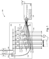
- FIG. 1 is a circuit diagram of a load center 100 in accordance with aspects of one embodiment of the present invention.
- the load center 100 includes a housing 101. Within the housing 101, the load center 100 includes an input power line 104, a plurality of input power line circuit branches 102, a plurality of neutral line circuit branches 106, and a neutral line 108.
- the input power line 104 and the neutral line 108 are configured to be coupled to an external power source (e.g., a utility power system).
- Each one of the plurality of input power line circuit branches 102 is coupled between the input power line 104 and an external load 112 (e.g., an appliance, a power outlet, a light etc.).
- Each one of the plurality of neutral line circuit branches 106 is coupled between the neutral line 108 and an external load 112.
- the input power line 104 includes a circuit breaker 113 coupled between the external power source and the input power line 104 and the neutral line 108 includes a circuit breaker 113 coupled between the external power source and the neutral line 108.
- each one of the plurality of circuit branches 102 includes a circuit breaker 115 coupled between the input power line 104 and an external load 112.
- the current rating of each of the circuit breakers 113, 115 may be configured based on the power required by the external load 112 to which the circuit breakers 113, 115 associated circuit branch 102 is coupled.
- the load center 100 also includes a plurality of Current Transformers (CT) 114 and a plurality of sensor circuits 120.
- CT Current Transformers
- Each one of the plurality of CT's 114 is coupled to at least one of the plurality of circuit branches 102.
- a CT 114 may also be coupled to the input power line 104.
- each CT 114 encompasses a corresponding circuit branch 102 or input power line 104.
- Each one of the plurality of CT's is also coupled to a corresponding sensor circuit 120.
- Each sensor circuit 120 is coupled to a terminal 127 of a CT concentrator 124 via a cable 122.
- the CT concentrator 124 is located external the housing 101; however, in other embodiments, the CT concentrator 124 is located within the housing 101.
- the CT concentrator 124 includes a plurality of terminals 127, a power module 126 and wireless radio module and antenna 128.
- the plurality of terminals 127 are RJ-11 connectors; however, in other embodiments, any other appropriate connector may be utilized.
- the power module 126 is a battery pack configured to provide DC power to the CT concentrator 124; however, in other embodiments, the power module receives AC power from the input power line 104 (e.g. via at least one branch circuit 102), converts the AC power to DC power and provides the DC power to the CT concentrator 124.
- AC power is provided from an external source (e.g., a utility power system) to the input power line 104.
- AC power from the input power line 104 is provided to each one of the external loads 112, via the loads associated circuit branch 102.
- the circuit breakers 113 are configured to automatically open and prevent current in the input power line 104 if an overload or short circuit is detected on the input power line 104.
- the circuit breakers 115 are configured to automatically open and prevent current in a circuit branch 102 if an overload or short circuit is detected in the circuit branch 102.
- AC current passing through a circuit branch 102 or input power line 104 induces a proportionate AC measurement signal in its associated CT 114 which encompasses the circuit branch 102 or input line 104.
- a CT 114 is coupled to multiple circuit branches 102
- an AC measurement signal proportionate to the combined current in the multiple circuit branches is induced in the CT 114 which encompasses the multiple circuit branches.
- the sensor circuit 120 coupled to the CT 114 transmits the proportionate AC measurement signals from the CT 114 to a terminal 127 of the CT concentrator 124 via its corresponding cable 122.
- the CT concentrator 124 receives the AC measurement signals from the sensor circuits 120.
- the CT concentrator 124 may display the current information to a user; analyze the received current information, use the current information in additional power calculations related to the associated circuit branches, transmit the information to an external client (e.g. a web server, in-home display, internet gateway, etc.) via the wireless radio module 128 or a hardwired connection, or any other appropriate action.
- an external client e.g. a web server, in-home display, internet gateway, etc.
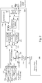
- FIG. 2 is a block diagram of a CT concentrator 124 in accordance with aspects of the present invention.
- the CT concentrator 124 has a plurality of terminals 127 which are configured to be connected to a plurality of sensor circuits 120 and CT's 114 via cables 122.
- the CT concentrator 124 includes a power module 126 and in one embodiment, the power module 126 is a battery pack.
- the battery pack includes 4 AA sized batteries connected in series and a DC interface 214.
- the power module 126 is modular and may be removed from the CT concentrator 124.
- the CT concentrator 124 includes a DC interface 216 configured to be coupled to the DC interface 214 of the battery pack 126.
- the DC interface 216 of the CT concentrator 124 is coupled to a power management module 224.
- the power management module 224 is coupled to a microcontroller 228.
- the microcontroller is coupled to the plurality of terminals 127.
- the microcontroller 228 includes an Analog to Digital Converter (ADC) which is configured to receive the analog current measurement signals from the terminals 127 (i.e. signals received at the terminals from the sensor circuits 120) and convert the analog signals to digital signals for further processing by the microcontroller 228.
- the CT concentrator 124 also includes a Real Time Clock (RTC) 229 coupled to the microcontroller 228.
- RTC Real Time Clock
- the CT concentrator 124 also includes a non-volatile memory module 232 coupled to the microcontroller 228.
- the non-volatile memory module 232 includes Electrically Erasable Programmable Read-Only Memory (EEPROM); however, in other embodiments, the non-volatile memory module 232 may include any type of non-volatile memory (e.g., such as serial Flash memory).
- EEPROM Electrically Erasable Programmable Read-Only Memory
- the CT concentrator 124 also includes a user interface 234 coupled to the microcontroller 228.
- the user interface may include any type of controls which allows a user to interface with the CT concentrator 124. (e.g., such controls include switches, buttons, LED's etc.).
- the CT concentrator 124 also includes a USB port 236 and a serial port 238.
- the CT concentrator 124 also includes the wireless radio module and antenna 128 coupled to the microcontroller 228.
- the wireless radio module 128 is a ZigBee radio; however, in other embodiments, the wireless radio module 128 may be configured using a different wireless standard.
- the wireless radio module and antenna 128 is also coupled to an On/Off switch 242 and a serial memory module 244.
- the battery pack 127 provides DC power to the CT concentrator 124 via the DC interface 214 and the DC interface 216.
- the power management module 224 receives the DC power from the first DC interface 216 and provides appropriate DC power to components of the CT concentrator 124 (e.g., the microcontroller 228).
- the microcontroller 228 Upon being powered, the microcontroller 228 monitors signals at the terminals 127 and based on the signals at each terminal, the microcontroller 228 determines whether a CT 114 (and sensor circuit 120) is coupled to each terminal.
- the microcontroller 228 compares the signals at each terminal to a pre-defined fixed signal envelope.
- the signal envelope is defined about a zero-crossing value at which analog measurement signals (received at the terminal 127 from a CT 114) would pass through under normal operating conditions (i.e. when a CT 114 is coupled to a terminal 127 and providing measurement signals to the terminal 127).
- the fixed signal envelope defines a first fixed signal level that is greater than the zero-crossing value and a second fixed signal level that is less than the zero-crossing value.
- the signal envelope is defined to be wide enough (i.e. the first and second fixed signal levels are far enough apart) that noise does not typically cause false tripping (i.e. the noise does not cause the signal to pass outside the signal envelope).
- the signal envelope is defined to be narrow enough (i.e. the first and second fixed signal levels are close enough) so that the connection of a sensor can be detected under a wide range of conditions and tolerances.
- the signals at the terminals 127 are compared to the signal envelope at a relatively fast rate (e.g. every 15 seconds). By comparing the signals to the signal envelope at a relatively fast rate, the microcontroller 228 is able to quickly determine, based on the signals at a terminal 127, whether the terminal 127 is connected to a CT 114.
- the microcontroller 228 If a signal at a terminal 127 passes outside of the signal envelope (i.e. is greater than the first fixed signal level or less than the second fixed signal level), the microcontroller 228 starts a countdown timer. If the signal received at the terminal passes back within the signal envelope (e.g. is less than the first fixed signal level and greater than the second fixed signal level), the microcontroller 228 resets the countdown timer. If the countdown timer expires prior to being reset, the microcontroller 228 determines, because the received signal has been outside of the signal envelope longer than would be expected for an analog measurement signal received from a CT 114 connected to the terminal 127, that the terminal is not connected to a CT 114. According to one embodiment, the value of the timer is defined so that a worst case signal frequency and amplitude is accounted for without false tripping.
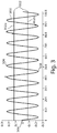
- FIG. 3 is a graph illustrating a measurement signal 300 output by a CT 114 (and received by the microcontroller 228 via a terminal 127) that is connected to a terminal 127 and to an associated circuit branch 102 that is providing power to a load 112.
- the measurement signal 300 is proportionate to current in the associated circuit branch 102.
- the graph of FIG. 3 also illustrates a fixed signal envelope 302 about the zero-crossing value 304 at which the received analog measurement signal 300 would pass through under normal operating conditions (i.e. when a CT 114 is coupled to a terminal 127).
- the fixed signal envelope includes a first fixed signal level 302a greater than the zero-crossing value and a second fixed signal level 302b less than the zero-crossing value.
- the measurement signal 300 is substantially within the signal envelope 302 and only portions of the measurement signal 300 near the peaks 306 and troughs 308 extend outside of the signal envelope 302 (i.e. are greater than the first fixed signal level 302a or less than the second fixed signal level 302b). However, as the measurement signal 300 passes back to within the signal envelope 302 (e.g. is less than the first fixed signal level 302a and greater than the second fixed signal level 302b), the microcontroller's 228 countdown timer (which was started once the signal 300 extended outside of the signal envelope 302) is reset and not allowed to expire. Therefore, upon receiving such a signal 300 as illustrated in FIG. 3 at a terminal 127, the microcontroller 228 identifies that the terminal 127 corresponding to the received signal 300 is coupled to a CT 114.
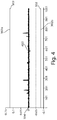
- FIG. 4 is a graph illustrating a measurement signal 400 output by a CT 114 (and received by the microcontroller 228 via a terminal 127) that is connected to a terminal 127 and to an associated circuit branch 102 that is not providing power to a load 112.
- the graph of FIG. 4 also illustrates the fixed signal envelope 302 (having the first fixed signal level 302a and the second fixed signal level 302b) about the zero-crossing value 304 at which the received analog measurement signal 400 would pass through under normal operating conditions (i.e. when a CT 114 is coupled to a terminal 127).
- the measurement signal 400 which is proportionate to current in the associated circuit branch 102, is substantially zero as the associated circuit branch 102 is not currently powering a load.
- the measurement signal 400 falls entirely within the signal envelope 302 (i.e. is less than the first fixed signal level 302a and greater than the second fixed signal level 302b).
- the microcontroller's 228 countdown timer is not started and hence, does not expire. Therefore, upon receiving such a signal 400 as illustrated in FIG. 4 at a terminal 127, the microcontroller 228 identifies that the terminal 127 corresponding to the received signal 400 is coupled to a CT 114.
- FIG. 5 is a graph illustrating a signal 500 at a terminal 127 that indicates to the microcontroller 228 that the terminal 127 is not connected to a CT 114.
- the graph of FIG. 5 also illustrates the fixed signal envelope 302 (having the first fixed signal level 302a and the second fixed signal level 302b) about the zero-crossing value 304 at which a received analog measurement signal 500 would pass through under normal operating conditions (i.e. when a CT 114 is coupled to a terminal 127).
- the signal 500 has an abnormal significant DC offset (which is not present when a terminal 127 is receiving appropriate measurement signals from a CT 114) and is entirely outside of the signal envelope 302 (i.e. entirely greater than the first fixed signal level 302a).
- a resistor in the CT 114 typically connects the ADC input of the microcontroller 228 to a DC bias voltage in the middle of the ADC's voltage range (the level of the DC bias is interpreted by the microcontroller as the zero-crossing value 304).
- the voltage signal e.g. signal 300
- the countdown timer of the microcontroller 228 Upon receiving a signal outside of the envelope 302 (e.g. high signal 500), the countdown timer of the microcontroller 228 starts and as the signal 500 does not pass back within the signal envelope 302 (i.e. less than the first fixed signal level 302a), the timer expires. Upon expiration of the timer, the microcontroller 228 identifies that the terminal 127 associated with the signal 500 is not actually connected to a CT 114.
- a signal outside of the envelope 302 e.g. high signal 500
- the microcontroller 228 By monitoring the actual signals at the terminals 127, which normally receive measurement signals from CT's 114, the microcontroller 228 is able to identify which terminals 127 are actually coupled to CT's 114, absent the need for a separate subsystem.
- the microcontroller 228 may take additional appropriate action with regards to the terminal 127. For example, in one embodiment, the microcontroller 228 activates a standard separate CT detection subsystem (as described above) to confirm that the terminal 127 is disconnected from a CT 114. In another embodiment, in an effort to save power, the microcontroller 228 stops monitoring the signals received from the CT 114 at the terminal 127 until a standard CT detection subsystem identifies that a new CT 114 has been connected to the terminal 127.
- FIG. 6 is a state diagram 600 of a method for detecting the presence of a current sensor (e.g. a CT 114) in accordance with aspects of the present invention.
- a current sensor e.g. a CT 114
- the microcontroller 228 is powered and monitors signals at a terminal 127 to determine whether the terminal 127 is connected to a CT 114.
- the microcontroller 228 In response to a determination 604 that the terminal 127 is still connected to a CT 114 (e.g. because the signals received at the terminal 127 are within the fixed signal envelope), the microcontroller 228 remains in state 602.
- the microcontroller 228 transitions to state 608.
- the microcontroller 228 In response to a determination 612 that the terminal 127 is still disconnected from a CT 114 (e.g. because the signals received at the terminal 127 are outside of the fixed signal envelope for longer than a predetermined amount of time), the microcontroller 228 remains in state 610.
- the microcontroller 228 transitions to state 608.
- the microcontroller 228 activates a standard sensing mechanism (e.g. a standard CT detection subsystem as described above) to confirm the connection status of the terminal 127.
- a standard sensing mechanism e.g. a standard CT detection subsystem as described above
- the microcontroller monitors terminals 127 to determine whether the terminals are connected to CT's; however, in other embodiments, the microcontroller may monitor the terminals 127 to determine whether the terminals are connected to any other type of current sensor.
- a terminal 127 disconnected from a CT 114 results in a high DC offset signal being provided to the microcontroller 228; however, in other embodiments, any other type of signal, outside of the fixed signal envelope for a predetermined amount of time, may signify to the microcontroller 228 that the terminal 127 is disconnected from the CT 114.
- the microcontroller 228 is able to quickly identify which terminals 127 are actually coupled to CT's 114, absent a separate subsystem (e.g., including a voltage divider as described above) which may waste power.
- a separate subsystem e.g., including a voltage divider as described above
Claims (11)
- Eine Systemüberwachungseinheit für eine Laststation (100), die Folgendes beinhaltet:einen Stromfühler, der konfiguriert ist, mit einer Abzweigungsschaltung innerhalb der Laststation gekoppelt zu werden und ein Messsignal mit einem Pegel, der sich auf einen Strompegel der Abzweigungsschaltung bezieht, zu produzieren;eine Sensorschaltung (120), die mit dem Stromfühler gekoppelt ist und entfernbar mit einem Terminal (127) gekoppelt ist, wobei die Sensorschaltung (120) konfiguriert ist, dem Terminal (127) das Messsignal bereitzustellen; undeinen Regler (228), der mit dem Terminal (127) gekoppelt ist und konfiguriert ist, Signale an dem Terminal zu überwachen, dadurch gekennzeichnet, dass der Regler ferner konfiguriert ist, eine Trennung des Stromfühlers von dem Terminal zu erkennen, basierend darauf, dass der Pegel des Messsignals an dem Terminal für einen vorbestimmten Zeitraum außerhalb einer vorbestimmten Einhüllenden liegt,wobei der Regler einen Zeitgeber mit einem Wert, der gleich dem vorbestimmten Zeitraum ist, umfasst und wobei der Regler ferner konfiguriert ist, den Zeitgeber als Reaktion auf das Erkennen, dass der Signalpegel an dem Terminal außerhalb einer vorbestimmten Einhüllenden liegt, zu starten und als Reaktion auf das Ablaufen des Zeitgebers zu bestimmen, dass der Stromfühler von dem Terminal getrennt ist.
- System gemäß Anspruch 1, wobei der Regler (228) ferner konfiguriert ist, eine Verbindung des Stromfühlers mit dem Terminal (127) zu erkennen, basierend darauf, dass das Messsignal an dem Terminal innerhalb der vorbestimmten Einhüllenden liegt.
- System gemäß Anspruch 1, wobei der Regler (228) ferner konfiguriert ist, den Zeitgeber als Reaktion darauf, dass das Messsignal an dem Terminal innerhalb der vorbestimmten Einhüllenden liegt, nachdem es vorher außerhalb der vorbestimmten Einhüllenden lag, zurückzusetzen.
- System gemäß Anspruch 1, wobei der Stromfühler einen Stromtransformator (114) umfasst.
- System gemäß Anspruch 1, wobei die vorbestimmte Einhüllende um einen Nulldurchgangswert definiert wird.
- Ein Verfahren zur Überwachung eines Stroms in einer Laststation (100) unter Verwendung eines Stromfühlers, der mit einer Abzweigungsschaltung (102) innerhalb der Laststation gekoppelt ist, wobei das Verfahren Folgendes beinhaltet:
Überwachen von Signalen an einem Terminal (127); dadurch gekennzeichnet, dass das Verfahren ferner Folgendes beinhaltet:Vergleichen eines Signalpegels an dem Terminal mit einer vorbestimmten Einhüllenden;Bestimmen, dass der Signalpegel an dem Terminal außerhalb der vorbestimmten Einhüllenden liegt;Starten eines Zeitgebers als Reaktion auf das Bestimmen, dass der Signalpegel an dem Terminal außerhalb der vorbestimmten Einhüllenden liegt; undIdentifizieren, als Reaktion auf das Ablaufen des Zeitgebers, dass der Stromfühler von dem Terminal getrennt ist. - Verfahren gemäß Anspruch 6, ferner beinhaltend das Zurücksetzen des Zeitgebers als Reaktion auf das Bestimmen, dass der Signalpegel an dem Terminal innerhalb der vorbestimmten Einhüllenden liegt, nachdem er vorher außerhalb der vorbestimmten Einhüllenden lag.
- Verfahren gemäß Anspruch 6, ferner beinhaltend das Identifizieren, als Reaktion darauf, dass der Signalpegel an dem Terminal innerhalb der vorbestimmten Einhüllenden liegt, dass der Stromfühler mit dem Terminal verbunden ist.
- Verfahren gemäß Anspruch 6, ferner beinhaltend das Einstellen der Überwachung von Signalen an dem Terminal als Reaktion auf das Identifizieren, dass der Stromfühler von dem Terminal getrennt ist.
- Verfahren gemäß Anspruch 6, wobei der Stromfühler einen Stromtransformator umfasst.
- Verfahren gemäß Anspruch 6, ferner beinhaltend das Definieren der vorbestimmten Einhüllenden um einen Nulldurchgang.
Applications Claiming Priority (1)
| Application Number | Priority Date | Filing Date | Title |
|---|---|---|---|
| PCT/US2012/033258 WO2013154563A1 (en) | 2012-04-12 | 2012-04-12 | System and method for detecting branch circuit current |
Publications (3)
| Publication Number | Publication Date |
|---|---|
| EP2836848A1 EP2836848A1 (de) | 2015-02-18 |
| EP2836848A4 EP2836848A4 (de) | 2015-12-02 |
| EP2836848B1 true EP2836848B1 (de) | 2020-04-01 |
Family
ID=49327983
Family Applications (1)
| Application Number | Title | Priority Date | Filing Date |
|---|---|---|---|
| EP12874241.8A Active EP2836848B1 (de) | 2012-04-12 | 2012-04-12 | System und verfahren zur erkennung eines abzweigkreisstroms |
Country Status (7)
| Country | Link |
|---|---|
| US (1) | US9638726B2 (de) |
| EP (1) | EP2836848B1 (de) |
| CN (1) | CN104350388B (de) |
| AU (1) | AU2012376819B2 (de) |
| DK (1) | DK2836848T3 (de) |
| IN (1) | IN2014DN09331A (de) |
| WO (1) | WO2013154563A1 (de) |
Families Citing this family (14)
| Publication number | Priority date | Publication date | Assignee | Title |
|---|---|---|---|---|
| US9880205B2 (en) | 2013-10-07 | 2018-01-30 | Schneider Electric It Corporation | Minimizing blind spots in a sensor network |
| WO2015069232A1 (en) | 2013-11-06 | 2015-05-14 | Schneider Electric It Corporation | Intelligent sensor network in a load center |
| EP3087451A4 (de) * | 2013-12-26 | 2017-11-01 | Schneider Electric IT Corporation | Systeme und verfahren zur bestimmung des eingangsstroms einer stromverteilereinheit |
| WO2015167576A1 (en) * | 2014-05-02 | 2015-11-05 | Schneider Electric It Corporation | Blind spot mitigation in a sensor network |
| DE202014007077U1 (de) * | 2014-09-04 | 2015-12-08 | EurA Consult AG | Strommesszange |
| US10345348B2 (en) * | 2014-11-04 | 2019-07-09 | Stmicroelectronics S.R.L. | Detection circuit for an active discharge circuit of an X-capacitor, related active discharge circuit, integrated circuit and method |
| KR102544778B1 (ko) * | 2016-06-16 | 2023-06-19 | 삼성전자주식회사 | 누설 전류를 검출하기 위한 방법 및 이를 지원하는 전자 장치 |
| US10750252B2 (en) | 2017-02-22 | 2020-08-18 | Sense Labs, Inc. | Identifying device state changes using power data and network data |
| CN108205090B (zh) * | 2017-12-28 | 2020-07-03 | 国网智能科技股份有限公司 | 一种可配置模块变电站负载支路检测方法和装置 |
| US10740691B2 (en) | 2018-10-02 | 2020-08-11 | Sense Labs, Inc. | Identifying devices connected to a smart plug |
| US11768228B2 (en) * | 2019-07-11 | 2023-09-26 | Sense Labs, Inc. | Current transformer with calibration information |
| CN110749842B (zh) * | 2019-11-08 | 2020-11-27 | 中南大学 | 基于共模电压的电压源型逆变器开关开路故障诊断方法 |
| CN110829592A (zh) * | 2019-11-12 | 2020-02-21 | 江西派源科技有限公司 | 一种半侵入式家用负荷监测方法 |
| WO2021224078A1 (de) * | 2020-05-05 | 2021-11-11 | Siemens Mobility GmbH | Anordnung zur erfassung des zustands einer elektronischen schaltung |
Family Cites Families (78)
| Publication number | Priority date | Publication date | Assignee | Title |
|---|---|---|---|---|
| US4158808A (en) | 1977-08-18 | 1979-06-19 | The Valeron Corporation | Load source simulator |
| US4258348A (en) | 1979-11-13 | 1981-03-24 | Stb Transformer Company | Current measuring transformer |
| US5117325A (en) | 1990-01-23 | 1992-05-26 | Cooper Industries, Inc. | Controllable recloser for power line |
| US5179376A (en) | 1991-02-28 | 1993-01-12 | Systems Analysis And Integration, Inc. | Substation load distribution monitor system |
| CA2091962A1 (en) | 1992-03-31 | 1993-10-01 | Mark L. Witsaman | Clock synchronization system |
| US5831428A (en) | 1993-11-30 | 1998-11-03 | Square D Company | Metering unit with integrated user programmable logic |
| US6792337B2 (en) | 1994-12-30 | 2004-09-14 | Power Measurement Ltd. | Method and system for master slave protocol communication in an intelligent electronic device |
| US6452767B1 (en) | 1995-03-13 | 2002-09-17 | Square D Company | Arcing fault detection system for a secondary line of a current transformer |
| US6313641B1 (en) | 1995-03-13 | 2001-11-06 | Square D Company | Method and system for detecting arcing faults and testing such system |
| FR2732164B1 (fr) | 1995-03-20 | 1997-04-30 | Alcatel Cable Interface | Reglette de connexion de lignes a haut debit et ensemble resultant de connexion |
| DE29512624U1 (de) | 1995-08-05 | 1995-11-30 | Slg Pruef Und Zertifizierungs | Stromzange |
| DE19612575C2 (de) | 1996-03-29 | 1999-11-18 | Endress Hauser Gmbh Co | Vorrichtung zur lösbaren Befestigung von Geräten und zu deren elektrischem Anschließen |
| US5995911A (en) | 1997-02-12 | 1999-11-30 | Power Measurement Ltd. | Digital sensor apparatus and system for protection, control, and management of electricity distribution systems |
| US5896027A (en) | 1997-03-27 | 1999-04-20 | National Research Council Of Canada | Current ratio device for use in forming a current transformer |
| US5959818A (en) | 1997-06-30 | 1999-09-28 | Eaton Corporation | Method and apparatus for self-powered three-phase sensing to determine true RMS current values with separate burdens for each current transformer |
| US6292108B1 (en) | 1997-09-04 | 2001-09-18 | The Board Of Trustees Of The Leland Standford Junior University | Modular, wireless damage monitoring system for structures |
| US6292717B1 (en) | 1998-03-19 | 2001-09-18 | Siemens Energy & Automation, Inc. | Energy information device and graphical display for a circuit breaker |
| US6064192A (en) | 1998-04-08 | 2000-05-16 | Ohio Semitronics | Revenue meter with integral current transformer |
| US6373238B2 (en) | 1998-07-06 | 2002-04-16 | Veris Industries, Llc | Three-phase electrical power measurement system including three transformers and a measurement circuit to calculate the power thereof |
| SE9802762D0 (sv) * | 1998-08-19 | 1998-08-19 | Siemens Elema Ab | Zero crossing detector and method of determining a zero crossing point |
| US6243626B1 (en) * | 1998-10-28 | 2001-06-05 | Bayview Technology Group, Inc. | External power management device with current monitoring precluding shutdown during high current |
| US6291986B1 (en) | 1999-06-15 | 2001-09-18 | Sheldon J. Sorensen | Insert for measuring current in conductors within an electrical enclosure |
| US6091237A (en) | 1999-09-14 | 2000-07-18 | Chen; Lee-Fei | Three-phrase clamp-type power meter |
| EP1102073A1 (de) | 1999-11-15 | 2001-05-23 | Alexander Patrick Corcoran | Strömungsüberwachung in Echtzeit |
| US6330516B1 (en) | 2000-03-27 | 2001-12-11 | Power Distribution, Inc. | Branch circuit monitor |
| US6788508B2 (en) | 2001-11-06 | 2004-09-07 | General Electric Company | Compact low AMP electronic circuit breaker or residential load center |
| DE10201495A1 (de) | 2002-01-17 | 2003-08-14 | Wieland Electric Gmbh | Elektrische Anschlussklemme |
| US7009348B2 (en) | 2002-06-03 | 2006-03-07 | Systel Development & Industries Ltd. | Multiple channel ballast and networkable topology and system including power line carrier applications |
| US20040075343A1 (en) | 2002-09-05 | 2004-04-22 | Paul Wareham | System and method for power load management |
| ITBG20020027A1 (it) | 2002-09-12 | 2004-03-13 | Abb Service Srl | Dispositivo per la misura di correnti e relativo metodo |
| US6835089B2 (en) | 2002-11-27 | 2004-12-28 | Fci Americas Technology, Inc. | Flex cable and IDC electrical wiring harness assembly |
| US7253640B2 (en) | 2003-01-13 | 2007-08-07 | Eaton Corporation | Arc fault detector and method for locating an arc fault |
| US6865073B2 (en) | 2003-03-06 | 2005-03-08 | General Electric Company | Panelboard metering arrangement and method of assembly thereof |
| US7174261B2 (en) | 2003-03-19 | 2007-02-06 | Power Measurement Ltd. | Power line sensors and systems incorporating same |
| US7412338B2 (en) | 2004-03-18 | 2008-08-12 | Power Measurement Ltd. | Radio frequency device within an energy sensor system |
| DE10342719A1 (de) | 2003-09-16 | 2005-04-21 | Bosch Gmbh Robert | Elektronischer Schaltkreis zum Bereitstellen einer Versorgungsspannung für einen elektronischen Verbraucher |
| US7451003B2 (en) | 2004-03-04 | 2008-11-11 | Falconeer Technologies Llc | Method and system of monitoring, sensor validation and predictive fault analysis |
| US7265533B2 (en) | 2004-06-15 | 2007-09-04 | Power Measurement Ltd. | Non-intrusive power monitor |
| DE602004017297D1 (de) | 2004-07-16 | 2008-12-04 | Lem Liaisons Electron Mec | Stromsensor |
| EP1782551B1 (de) | 2004-07-30 | 2016-10-05 | CommScope Technologies LLC | Leistungsregelung in einem lokalen netzwerkknoten (lnn) |
| WO2006021030A1 (en) | 2004-08-23 | 2006-03-02 | Fault Detectors Pty Ltd | Electrical power line sensing and sensor assembly |
| US7453267B2 (en) | 2005-01-14 | 2008-11-18 | Power Measurement Ltd. | Branch circuit monitor system |
| US7571063B2 (en) | 2006-04-28 | 2009-08-04 | Admmicro Properties Llc | Lighting performance power monitoring system and method with optional integrated light control |
| US8093745B2 (en) | 2006-07-07 | 2012-01-10 | Ambient Corporation | Sensing current flowing through a power line |
| US8332567B2 (en) | 2006-09-19 | 2012-12-11 | Fisher-Rosemount Systems, Inc. | Apparatus and methods to communicatively couple field devices to controllers in a process control system |
| US20080180275A1 (en) | 2007-01-30 | 2008-07-31 | Cimarron Systems, Llc | Communication System For Multi-Tiered Network |
| JP2008245202A (ja) | 2007-03-29 | 2008-10-09 | Yamaha Corp | 電力線搬送通信用ブリッジ回路および電力線搬送通信用ネットワーク機器 |
| DE102007017836B4 (de) | 2007-04-16 | 2017-02-02 | Eaton Industries Gmbh | Busstecker für ein Flachbandkabel sowie zugehöriges Verfahren zu dessen Anbringung |
| CN201035075Y (zh) | 2007-04-17 | 2008-03-12 | 山东力创科技有限公司 | Eda9133综合电力监控仪 |
| JP5199358B2 (ja) | 2007-07-13 | 2013-05-15 | キネックツ ソリューションズ インコーポレイテッド | 変圧器用メータおよびそれを使用するシステム |
| CA2609611A1 (en) | 2007-09-10 | 2009-03-10 | Veris Industries, Llc | Split core status indicator |
| US9383394B2 (en) | 2007-11-02 | 2016-07-05 | Cooper Technologies Company | Overhead communicating device |
| US8004226B2 (en) | 2008-08-06 | 2011-08-23 | Caterpillar Inc. | Method and system for detecting a failed current sensor in a three-phase machine |
| US8004418B2 (en) | 2008-09-08 | 2011-08-23 | Eaton Corporation | Communication interface apparatus for an electrical distribution panel, and system and electrical distribution panel including the same |
| US8321163B2 (en) | 2009-03-04 | 2012-11-27 | Server Technology, Inc. | Monitoring power-related parameters in a power distribution unit |
| US9335352B2 (en) * | 2009-03-13 | 2016-05-10 | Veris Industries, Llc | Branch circuit monitor power measurement |
| US8193803B2 (en) | 2009-03-23 | 2012-06-05 | Consolidated Edison Company Of New York, Inc. | Current measuring device |
| GB2498884B (en) | 2009-04-16 | 2014-02-12 | Panoramic Power Ltd | Apparatus and methods thereof for power consumption measurement at circuit breaker points |
| US9134348B2 (en) | 2009-04-16 | 2015-09-15 | Panoramic Power Ltd. | Distributed electricity metering system |
| US8190697B2 (en) | 2009-05-20 | 2012-05-29 | Square D Company | Automated configuration of device communication settings |
| US8624578B2 (en) | 2009-06-04 | 2014-01-07 | Veris Industries, Llc | Branch current monitor with configuration |
| US8305737B2 (en) | 2009-06-25 | 2012-11-06 | Server Technology, Inc. | Power distribution apparatus with input and output power sensing and method of use |
| US8626344B2 (en) | 2009-08-21 | 2014-01-07 | Allure Energy, Inc. | Energy management system and method |
| CN201667273U (zh) | 2009-11-27 | 2010-12-08 | 厦门安达兴电气有限公司 | 一种电流互感器的结构 |
| US8493053B2 (en) | 2009-12-18 | 2013-07-23 | GRID20/20, Inc. | System and device for measuring voltage in a conductor |
| FR2956212B1 (fr) | 2010-02-08 | 2012-03-09 | Schneider Electric Ind Sas | Dispositif et procede de comptage d'energie electrique |
| US9267826B2 (en) * | 2010-05-28 | 2016-02-23 | Schneider Electric It Corporation | System for self-powered, wireless monitoring of electrical current, power and energy |
| US8958923B2 (en) | 2010-08-02 | 2015-02-17 | Panasonic Intellectual Property Management Co., Ltd. | Distributed power supply system and control method thereof |
| US8563882B2 (en) | 2010-10-12 | 2013-10-22 | Siemens Industry, Inc. | Electronic circuit breaker having a locking and unlocking mechanism and methods of operating same |
| JP5741010B2 (ja) | 2011-01-26 | 2015-07-01 | 日本電気株式会社 | 同期システム |
| US9588160B2 (en) * | 2011-02-09 | 2017-03-07 | International Business Machines Corporation | Wire manager with current and voltage sensing |
| CN102122810B (zh) | 2011-03-11 | 2013-11-06 | 上海诺雅克电气有限公司 | 用于监测电流互感器状态的电流诊断装置及其诊断方法 |
| US8666685B2 (en) | 2011-04-19 | 2014-03-04 | Schneider Electronic IT Corporation | System of intelligent sensors in an electrical panelboard |
| US8787372B2 (en) | 2011-04-19 | 2014-07-22 | Schneider Electric It Corporation | System and method for transferring data in a multi-drop network |
| US8660810B2 (en) | 2011-04-19 | 2014-02-25 | Schneider Electric It Corporation | System and method to calculate RMS current and true power in a multidrop sensor network |
| US8700747B2 (en) | 2011-04-19 | 2014-04-15 | Schneider Electric It Corporation | System and method for automatically addressing devices in a multi-drop network |
| US9031800B2 (en) | 2011-07-13 | 2015-05-12 | Schneider Electric USA, Inc. | Power determination from separated voltage and current sensors |
| CN102393485A (zh) | 2011-09-16 | 2012-03-28 | 福建俊豪电子有限公司 | 多回路漏电电流检测模块 |
-
2012
- 2012-04-12 US US14/391,332 patent/US9638726B2/en active Active
- 2012-04-12 IN IN9331DEN2014 patent/IN2014DN09331A/en unknown
- 2012-04-12 DK DK12874241.8T patent/DK2836848T3/da active
- 2012-04-12 AU AU2012376819A patent/AU2012376819B2/en active Active
- 2012-04-12 CN CN201280073890.8A patent/CN104350388B/zh active Active
- 2012-04-12 EP EP12874241.8A patent/EP2836848B1/de active Active
- 2012-04-12 WO PCT/US2012/033258 patent/WO2013154563A1/en active Application Filing
Non-Patent Citations (1)
| Title |
|---|
| None * |
Also Published As
| Publication number | Publication date |
|---|---|
| IN2014DN09331A (de) | 2015-07-10 |
| EP2836848A1 (de) | 2015-02-18 |
| WO2013154563A1 (en) | 2013-10-17 |
| CN104350388A (zh) | 2015-02-11 |
| CN104350388B (zh) | 2017-06-20 |
| US9638726B2 (en) | 2017-05-02 |
| EP2836848A4 (de) | 2015-12-02 |
| AU2012376819A1 (en) | 2014-11-06 |
| AU2012376819B2 (en) | 2017-04-20 |
| US20150102800A1 (en) | 2015-04-16 |
| DK2836848T3 (da) | 2020-06-15 |
Similar Documents
| Publication | Publication Date | Title |
|---|---|---|
| EP2836848B1 (de) | System und verfahren zur erkennung eines abzweigkreisstroms | |
| US7282921B2 (en) | System, apparatus and method for detection of electrical faults | |
| US8310370B1 (en) | Smart circuit breaker with integrated energy management interface | |
| JP5235908B2 (ja) | 電力計測システム、機器制御システム | |
| CN105186227A (zh) | 一种智能插座 | |
| CN204927711U (zh) | 一种智能插座 | |
| CN1097864C (zh) | 插座 | |
| JP2010181378A (ja) | 電力計測装置及び機器制御装置 | |
| KR101362777B1 (ko) | 무선 통신 기반 콘센트 장치 및 대기전력 차단 방법 | |
| JP6305044B2 (ja) | 電力計測装置及び電力計測方法 | |
| EP2270945B1 (de) | System und Verfahren zum Messen des Lasttyps in einem menschlichen Körpermodell | |
| JP2010019680A (ja) | 電力量計 | |
| KR101073809B1 (ko) | 스마트 대기전력 자동차단 스위치 | |
| CN106961155A (zh) | 一种具备用电数据监测及安全功能的智能配电接入系统 | |
| KR101024628B1 (ko) | 온도검출을 통한 화재 방지용 전자식 전력량계 | |
| AU2019101016A4 (en) | Voltage Protection Device | |
| US11536754B2 (en) | Electricity meter with fault tolerant power supply | |
| KR101452751B1 (ko) | 전력량계, 전력량계 시스템 및 전력량계의 동작방법 | |
| AU2019101017A4 (en) | Voltage Protection Device | |
| KR101325336B1 (ko) | 대기전력 체크 시스템 | |
| CN217846462U (zh) | 一种电源输出电容值检测系统及装置 | |
| KR101198475B1 (ko) | 대기전력 차단기능을 구비한 멀티탭 | |
| FI20195014A1 (en) | Electrical outlet system and method for electrical outlet system | |
| KR20100131293A (ko) | 수요전력 제어장치 및 수요전력 제어방법 |
Legal Events
| Date | Code | Title | Description |
|---|---|---|---|
| PUAI | Public reference made under article 153(3) epc to a published international application that has entered the european phase |
Free format text: ORIGINAL CODE: 0009012 |
|
| 17P | Request for examination filed |
Effective date: 20141010 |
|
| AK | Designated contracting states |
Kind code of ref document: A1 Designated state(s): AL AT BE BG CH CY CZ DE DK EE ES FI FR GB GR HR HU IE IS IT LI LT LU LV MC MK MT NL NO PL PT RO RS SE SI SK SM TR |
|
| AX | Request for extension of the european patent |
Extension state: BA ME |
|
| RIN1 | Information on inventor provided before grant (corrected) |
Inventor name: ORNER, BRET, ALAN Inventor name: DEOKAR, VISHWAS, MOHANIRAJ Inventor name: MEARNS, BRIAN, PATRICK |
|
| DAX | Request for extension of the european patent (deleted) | ||
| RA4 | Supplementary search report drawn up and despatched (corrected) |
Effective date: 20151102 |
|
| RIC1 | Information provided on ipc code assigned before grant |
Ipc: G01R 35/00 20060101ALI20151027BHEP Ipc: G01R 31/02 20060101ALI20151027BHEP Ipc: G01R 19/00 20060101AFI20151027BHEP |
|
| STAA | Information on the status of an ep patent application or granted ep patent |
Free format text: STATUS: EXAMINATION IS IN PROGRESS |
|
| 17Q | First examination report despatched |
Effective date: 20180406 |
|
| RIC1 | Information provided on ipc code assigned before grant |
Ipc: G01R 31/28 20060101ALI20190715BHEP Ipc: G01R 31/02 20060101AFI20190715BHEP |
|
| GRAP | Despatch of communication of intention to grant a patent |
Free format text: ORIGINAL CODE: EPIDOSNIGR1 |
|
| STAA | Information on the status of an ep patent application or granted ep patent |
Free format text: STATUS: GRANT OF PATENT IS INTENDED |
|
| INTG | Intention to grant announced |
Effective date: 20191011 |
|
| GRAS | Grant fee paid |
Free format text: ORIGINAL CODE: EPIDOSNIGR3 |
|
| GRAJ | Information related to disapproval of communication of intention to grant by the applicant or resumption of examination proceedings by the epo deleted |
Free format text: ORIGINAL CODE: EPIDOSDIGR1 |
|
| GRAL | Information related to payment of fee for publishing/printing deleted |
Free format text: ORIGINAL CODE: EPIDOSDIGR3 |
|
| REG | Reference to a national code |
Ref country code: DE Ref legal event code: R079 Ref document number: 602012068999 Country of ref document: DE Free format text: PREVIOUS MAIN CLASS: G01R0019000000 Ipc: G01R0031280000 |
|
| STAA | Information on the status of an ep patent application or granted ep patent |
Free format text: STATUS: EXAMINATION IS IN PROGRESS |
|
| GRAR | Information related to intention to grant a patent recorded |
Free format text: ORIGINAL CODE: EPIDOSNIGR71 |
|
| STAA | Information on the status of an ep patent application or granted ep patent |
Free format text: STATUS: GRANT OF PATENT IS INTENDED |
|
| GRAA | (expected) grant |
Free format text: ORIGINAL CODE: 0009210 |
|
| STAA | Information on the status of an ep patent application or granted ep patent |
Free format text: STATUS: THE PATENT HAS BEEN GRANTED |
|
| INTC | Intention to grant announced (deleted) | ||
| RIC1 | Information provided on ipc code assigned before grant |
Ipc: G01R 31/28 20060101AFI20200207BHEP Ipc: G01R 31/54 20200101ALI20200207BHEP |
|
| INTG | Intention to grant announced |
Effective date: 20200219 |
|
| AK | Designated contracting states |
Kind code of ref document: B1 Designated state(s): AL AT BE BG CH CY CZ DE DK EE ES FI FR GB GR HR HU IE IS IT LI LT LU LV MC MK MT NL NO PL PT RO RS SE SI SK SM TR |
|
| REG | Reference to a national code |
Ref country code: GB Ref legal event code: FG4D |
|
| REG | Reference to a national code |
Ref country code: CH Ref legal event code: EP Ref country code: AT Ref legal event code: REF Ref document number: 1252072 Country of ref document: AT Kind code of ref document: T Effective date: 20200415 |
|
| REG | Reference to a national code |
Ref country code: DE Ref legal event code: R096 Ref document number: 602012068999 Country of ref document: DE |
|
| REG | Reference to a national code |
Ref country code: IE Ref legal event code: FG4D |
|
| REG | Reference to a national code |
Ref country code: DK Ref legal event code: T3 Effective date: 20200609 |
|
| PG25 | Lapsed in a contracting state [announced via postgrant information from national office to epo] |
Ref country code: BG Free format text: LAPSE BECAUSE OF FAILURE TO SUBMIT A TRANSLATION OF THE DESCRIPTION OR TO PAY THE FEE WITHIN THE PRESCRIBED TIME-LIMIT Effective date: 20200701 |
|
| REG | Reference to a national code |
Ref country code: NL Ref legal event code: MP Effective date: 20200401 |
|
| REG | Reference to a national code |
Ref country code: LT Ref legal event code: MG4D |
|
| PG25 | Lapsed in a contracting state [announced via postgrant information from national office to epo] |
Ref country code: IS Free format text: LAPSE BECAUSE OF FAILURE TO SUBMIT A TRANSLATION OF THE DESCRIPTION OR TO PAY THE FEE WITHIN THE PRESCRIBED TIME-LIMIT Effective date: 20200801 Ref country code: CZ Free format text: LAPSE BECAUSE OF FAILURE TO SUBMIT A TRANSLATION OF THE DESCRIPTION OR TO PAY THE FEE WITHIN THE PRESCRIBED TIME-LIMIT Effective date: 20200401 Ref country code: FI Free format text: LAPSE BECAUSE OF FAILURE TO SUBMIT A TRANSLATION OF THE DESCRIPTION OR TO PAY THE FEE WITHIN THE PRESCRIBED TIME-LIMIT Effective date: 20200401 Ref country code: NO Free format text: LAPSE BECAUSE OF FAILURE TO SUBMIT A TRANSLATION OF THE DESCRIPTION OR TO PAY THE FEE WITHIN THE PRESCRIBED TIME-LIMIT Effective date: 20200701 Ref country code: GR Free format text: LAPSE BECAUSE OF FAILURE TO SUBMIT A TRANSLATION OF THE DESCRIPTION OR TO PAY THE FEE WITHIN THE PRESCRIBED TIME-LIMIT Effective date: 20200702 Ref country code: SE Free format text: LAPSE BECAUSE OF FAILURE TO SUBMIT A TRANSLATION OF THE DESCRIPTION OR TO PAY THE FEE WITHIN THE PRESCRIBED TIME-LIMIT Effective date: 20200401 Ref country code: NL Free format text: LAPSE BECAUSE OF FAILURE TO SUBMIT A TRANSLATION OF THE DESCRIPTION OR TO PAY THE FEE WITHIN THE PRESCRIBED TIME-LIMIT Effective date: 20200401 Ref country code: LT Free format text: LAPSE BECAUSE OF FAILURE TO SUBMIT A TRANSLATION OF THE DESCRIPTION OR TO PAY THE FEE WITHIN THE PRESCRIBED TIME-LIMIT Effective date: 20200401 Ref country code: PT Free format text: LAPSE BECAUSE OF FAILURE TO SUBMIT A TRANSLATION OF THE DESCRIPTION OR TO PAY THE FEE WITHIN THE PRESCRIBED TIME-LIMIT Effective date: 20200817 |
|
| REG | Reference to a national code |
Ref country code: AT Ref legal event code: MK05 Ref document number: 1252072 Country of ref document: AT Kind code of ref document: T Effective date: 20200401 |
|
| PG25 | Lapsed in a contracting state [announced via postgrant information from national office to epo] |
Ref country code: HR Free format text: LAPSE BECAUSE OF FAILURE TO SUBMIT A TRANSLATION OF THE DESCRIPTION OR TO PAY THE FEE WITHIN THE PRESCRIBED TIME-LIMIT Effective date: 20200401 Ref country code: LV Free format text: LAPSE BECAUSE OF FAILURE TO SUBMIT A TRANSLATION OF THE DESCRIPTION OR TO PAY THE FEE WITHIN THE PRESCRIBED TIME-LIMIT Effective date: 20200401 Ref country code: RS Free format text: LAPSE BECAUSE OF FAILURE TO SUBMIT A TRANSLATION OF THE DESCRIPTION OR TO PAY THE FEE WITHIN THE PRESCRIBED TIME-LIMIT Effective date: 20200401 |
|
| REG | Reference to a national code |
Ref country code: CH Ref legal event code: PL |
|
| PG25 | Lapsed in a contracting state [announced via postgrant information from national office to epo] |
Ref country code: AL Free format text: LAPSE BECAUSE OF FAILURE TO SUBMIT A TRANSLATION OF THE DESCRIPTION OR TO PAY THE FEE WITHIN THE PRESCRIBED TIME-LIMIT Effective date: 20200401 |
|
| REG | Reference to a national code |
Ref country code: DE Ref legal event code: R097 Ref document number: 602012068999 Country of ref document: DE |
|
| PG25 | Lapsed in a contracting state [announced via postgrant information from national office to epo] |
Ref country code: AT Free format text: LAPSE BECAUSE OF FAILURE TO SUBMIT A TRANSLATION OF THE DESCRIPTION OR TO PAY THE FEE WITHIN THE PRESCRIBED TIME-LIMIT Effective date: 20200401 Ref country code: ES Free format text: LAPSE BECAUSE OF FAILURE TO SUBMIT A TRANSLATION OF THE DESCRIPTION OR TO PAY THE FEE WITHIN THE PRESCRIBED TIME-LIMIT Effective date: 20200401 Ref country code: CH Free format text: LAPSE BECAUSE OF NON-PAYMENT OF DUE FEES Effective date: 20200430 Ref country code: LI Free format text: LAPSE BECAUSE OF NON-PAYMENT OF DUE FEES Effective date: 20200430 Ref country code: MC Free format text: LAPSE BECAUSE OF FAILURE TO SUBMIT A TRANSLATION OF THE DESCRIPTION OR TO PAY THE FEE WITHIN THE PRESCRIBED TIME-LIMIT Effective date: 20200401 Ref country code: LU Free format text: LAPSE BECAUSE OF NON-PAYMENT OF DUE FEES Effective date: 20200412 Ref country code: RO Free format text: LAPSE BECAUSE OF FAILURE TO SUBMIT A TRANSLATION OF THE DESCRIPTION OR TO PAY THE FEE WITHIN THE PRESCRIBED TIME-LIMIT Effective date: 20200401 Ref country code: IT Free format text: LAPSE BECAUSE OF FAILURE TO SUBMIT A TRANSLATION OF THE DESCRIPTION OR TO PAY THE FEE WITHIN THE PRESCRIBED TIME-LIMIT Effective date: 20200401 Ref country code: SM Free format text: LAPSE BECAUSE OF FAILURE TO SUBMIT A TRANSLATION OF THE DESCRIPTION OR TO PAY THE FEE WITHIN THE PRESCRIBED TIME-LIMIT Effective date: 20200401 Ref country code: EE Free format text: LAPSE BECAUSE OF FAILURE TO SUBMIT A TRANSLATION OF THE DESCRIPTION OR TO PAY THE FEE WITHIN THE PRESCRIBED TIME-LIMIT Effective date: 20200401 |
|
| REG | Reference to a national code |
Ref country code: BE Ref legal event code: MM Effective date: 20200430 |
|
| PLBE | No opposition filed within time limit |
Free format text: ORIGINAL CODE: 0009261 |
|
| STAA | Information on the status of an ep patent application or granted ep patent |
Free format text: STATUS: NO OPPOSITION FILED WITHIN TIME LIMIT |
|
| PG25 | Lapsed in a contracting state [announced via postgrant information from national office to epo] |
Ref country code: PL Free format text: LAPSE BECAUSE OF FAILURE TO SUBMIT A TRANSLATION OF THE DESCRIPTION OR TO PAY THE FEE WITHIN THE PRESCRIBED TIME-LIMIT Effective date: 20200401 Ref country code: SK Free format text: LAPSE BECAUSE OF FAILURE TO SUBMIT A TRANSLATION OF THE DESCRIPTION OR TO PAY THE FEE WITHIN THE PRESCRIBED TIME-LIMIT Effective date: 20200401 Ref country code: BE Free format text: LAPSE BECAUSE OF NON-PAYMENT OF DUE FEES Effective date: 20200430 |
|
| 26N | No opposition filed |
Effective date: 20210112 |
|
| PG25 | Lapsed in a contracting state [announced via postgrant information from national office to epo] |
Ref country code: IE Free format text: LAPSE BECAUSE OF NON-PAYMENT OF DUE FEES Effective date: 20200412 |
|
| PG25 | Lapsed in a contracting state [announced via postgrant information from national office to epo] |
Ref country code: SI Free format text: LAPSE BECAUSE OF FAILURE TO SUBMIT A TRANSLATION OF THE DESCRIPTION OR TO PAY THE FEE WITHIN THE PRESCRIBED TIME-LIMIT Effective date: 20200401 |
|
| PG25 | Lapsed in a contracting state [announced via postgrant information from national office to epo] |
Ref country code: TR Free format text: LAPSE BECAUSE OF FAILURE TO SUBMIT A TRANSLATION OF THE DESCRIPTION OR TO PAY THE FEE WITHIN THE PRESCRIBED TIME-LIMIT Effective date: 20200401 Ref country code: MT Free format text: LAPSE BECAUSE OF FAILURE TO SUBMIT A TRANSLATION OF THE DESCRIPTION OR TO PAY THE FEE WITHIN THE PRESCRIBED TIME-LIMIT Effective date: 20200401 Ref country code: CY Free format text: LAPSE BECAUSE OF FAILURE TO SUBMIT A TRANSLATION OF THE DESCRIPTION OR TO PAY THE FEE WITHIN THE PRESCRIBED TIME-LIMIT Effective date: 20200401 |
|
| PG25 | Lapsed in a contracting state [announced via postgrant information from national office to epo] |
Ref country code: MK Free format text: LAPSE BECAUSE OF FAILURE TO SUBMIT A TRANSLATION OF THE DESCRIPTION OR TO PAY THE FEE WITHIN THE PRESCRIBED TIME-LIMIT Effective date: 20200401 |
|
| PGFP | Annual fee paid to national office [announced via postgrant information from national office to epo] |
Ref country code: FR Payment date: 20230421 Year of fee payment: 12 Ref country code: DK Payment date: 20230421 Year of fee payment: 12 Ref country code: DE Payment date: 20230427 Year of fee payment: 12 |
|
| PGFP | Annual fee paid to national office [announced via postgrant information from national office to epo] |
Ref country code: GB Payment date: 20230418 Year of fee payment: 12 |