EP2836724B1 - Fluid system and method of controlling a fluid system - Google Patents
Fluid system and method of controlling a fluid system Download PDFInfo
- Publication number
- EP2836724B1 EP2836724B1 EP13709779.6A EP13709779A EP2836724B1 EP 2836724 B1 EP2836724 B1 EP 2836724B1 EP 13709779 A EP13709779 A EP 13709779A EP 2836724 B1 EP2836724 B1 EP 2836724B1
- Authority
- EP
- European Patent Office
- Prior art keywords
- actuator
- control
- fluid
- safety
- valve control
- Prior art date
- Legal status (The legal status is an assumption and is not a legal conclusion. Google has not performed a legal analysis and makes no representation as to the accuracy of the status listed.)
- Active
Links
Images

Classifications
-
- G—PHYSICS
- G05—CONTROLLING; REGULATING
- G05B—CONTROL OR REGULATING SYSTEMS IN GENERAL; FUNCTIONAL ELEMENTS OF SUCH SYSTEMS; MONITORING OR TESTING ARRANGEMENTS FOR SUCH SYSTEMS OR ELEMENTS
- G05B19/00—Programme-control systems
- G05B19/02—Programme-control systems electric
- G05B19/04—Programme control other than numerical control, i.e. in sequence controllers or logic controllers
- G05B19/042—Programme control other than numerical control, i.e. in sequence controllers or logic controllers using digital processors
- G05B19/0428—Safety, monitoring
-
- F—MECHANICAL ENGINEERING; LIGHTING; HEATING; WEAPONS; BLASTING
- F15—FLUID-PRESSURE ACTUATORS; HYDRAULICS OR PNEUMATICS IN GENERAL
- F15B—SYSTEMS ACTING BY MEANS OF FLUIDS IN GENERAL; FLUID-PRESSURE ACTUATORS, e.g. SERVOMOTORS; DETAILS OF FLUID-PRESSURE SYSTEMS, NOT OTHERWISE PROVIDED FOR
- F15B19/00—Testing; Calibrating; Fault detection or monitoring; Simulation or modelling of fluid-pressure systems or apparatus not otherwise provided for
- F15B19/005—Fault detection or monitoring
-
- F—MECHANICAL ENGINEERING; LIGHTING; HEATING; WEAPONS; BLASTING
- F15—FLUID-PRESSURE ACTUATORS; HYDRAULICS OR PNEUMATICS IN GENERAL
- F15B—SYSTEMS ACTING BY MEANS OF FLUIDS IN GENERAL; FLUID-PRESSURE ACTUATORS, e.g. SERVOMOTORS; DETAILS OF FLUID-PRESSURE SYSTEMS, NOT OTHERWISE PROVIDED FOR
- F15B19/00—Testing; Calibrating; Fault detection or monitoring; Simulation or modelling of fluid-pressure systems or apparatus not otherwise provided for
-
- F—MECHANICAL ENGINEERING; LIGHTING; HEATING; WEAPONS; BLASTING
- F16—ENGINEERING ELEMENTS AND UNITS; GENERAL MEASURES FOR PRODUCING AND MAINTAINING EFFECTIVE FUNCTIONING OF MACHINES OR INSTALLATIONS; THERMAL INSULATION IN GENERAL
- F16P—SAFETY DEVICES IN GENERAL; SAFETY DEVICES FOR PRESSES
- F16P3/00—Safety devices acting in conjunction with the control or operation of a machine; Control arrangements requiring the simultaneous use of two or more parts of the body
- F16P3/12—Safety devices acting in conjunction with the control or operation of a machine; Control arrangements requiring the simultaneous use of two or more parts of the body with means, e.g. feelers, which in case of the presence of a body part of a person in or near the danger zone influence the control or operation of the machine
- F16P3/14—Safety devices acting in conjunction with the control or operation of a machine; Control arrangements requiring the simultaneous use of two or more parts of the body with means, e.g. feelers, which in case of the presence of a body part of a person in or near the danger zone influence the control or operation of the machine the means being photocells or other devices sensitive without mechanical contact
- F16P3/142—Safety devices acting in conjunction with the control or operation of a machine; Control arrangements requiring the simultaneous use of two or more parts of the body with means, e.g. feelers, which in case of the presence of a body part of a person in or near the danger zone influence the control or operation of the machine the means being photocells or other devices sensitive without mechanical contact using image capturing devices
-
- F—MECHANICAL ENGINEERING; LIGHTING; HEATING; WEAPONS; BLASTING
- F16—ENGINEERING ELEMENTS AND UNITS; GENERAL MEASURES FOR PRODUCING AND MAINTAINING EFFECTIVE FUNCTIONING OF MACHINES OR INSTALLATIONS; THERMAL INSULATION IN GENERAL
- F16P—SAFETY DEVICES IN GENERAL; SAFETY DEVICES FOR PRESSES
- F16P3/00—Safety devices acting in conjunction with the control or operation of a machine; Control arrangements requiring the simultaneous use of two or more parts of the body
- F16P3/12—Safety devices acting in conjunction with the control or operation of a machine; Control arrangements requiring the simultaneous use of two or more parts of the body with means, e.g. feelers, which in case of the presence of a body part of a person in or near the danger zone influence the control or operation of the machine
- F16P3/14—Safety devices acting in conjunction with the control or operation of a machine; Control arrangements requiring the simultaneous use of two or more parts of the body with means, e.g. feelers, which in case of the presence of a body part of a person in or near the danger zone influence the control or operation of the machine the means being photocells or other devices sensitive without mechanical contact
- F16P3/144—Safety devices acting in conjunction with the control or operation of a machine; Control arrangements requiring the simultaneous use of two or more parts of the body with means, e.g. feelers, which in case of the presence of a body part of a person in or near the danger zone influence the control or operation of the machine the means being photocells or other devices sensitive without mechanical contact using light grids
-
- Y—GENERAL TAGGING OF NEW TECHNOLOGICAL DEVELOPMENTS; GENERAL TAGGING OF CROSS-SECTIONAL TECHNOLOGIES SPANNING OVER SEVERAL SECTIONS OF THE IPC; TECHNICAL SUBJECTS COVERED BY FORMER USPC CROSS-REFERENCE ART COLLECTIONS [XRACs] AND DIGESTS
- Y10—TECHNICAL SUBJECTS COVERED BY FORMER USPC
- Y10T—TECHNICAL SUBJECTS COVERED BY FORMER US CLASSIFICATION
- Y10T137/00—Fluid handling
- Y10T137/0318—Processes
- Y10T137/0324—With control of flow by a condition or characteristic of a fluid
-
- Y—GENERAL TAGGING OF NEW TECHNOLOGICAL DEVELOPMENTS; GENERAL TAGGING OF CROSS-SECTIONAL TECHNOLOGIES SPANNING OVER SEVERAL SECTIONS OF THE IPC; TECHNICAL SUBJECTS COVERED BY FORMER USPC CROSS-REFERENCE ART COLLECTIONS [XRACs] AND DIGESTS
- Y10—TECHNICAL SUBJECTS COVERED BY FORMER USPC
- Y10T—TECHNICAL SUBJECTS COVERED BY FORMER US CLASSIFICATION
- Y10T137/00—Fluid handling
- Y10T137/7722—Line condition change responsive valves
-
- Y—GENERAL TAGGING OF NEW TECHNOLOGICAL DEVELOPMENTS; GENERAL TAGGING OF CROSS-SECTIONAL TECHNOLOGIES SPANNING OVER SEVERAL SECTIONS OF THE IPC; TECHNICAL SUBJECTS COVERED BY FORMER USPC CROSS-REFERENCE ART COLLECTIONS [XRACs] AND DIGESTS
- Y10—TECHNICAL SUBJECTS COVERED BY FORMER USPC
- Y10T—TECHNICAL SUBJECTS COVERED BY FORMER US CLASSIFICATION
- Y10T137/00—Fluid handling
- Y10T137/8158—With indicator, register, recorder, alarm or inspection means
- Y10T137/8175—Plural
-
- Y—GENERAL TAGGING OF NEW TECHNOLOGICAL DEVELOPMENTS; GENERAL TAGGING OF CROSS-SECTIONAL TECHNOLOGIES SPANNING OVER SEVERAL SECTIONS OF THE IPC; TECHNICAL SUBJECTS COVERED BY FORMER USPC CROSS-REFERENCE ART COLLECTIONS [XRACs] AND DIGESTS
- Y10—TECHNICAL SUBJECTS COVERED BY FORMER USPC
- Y10T—TECHNICAL SUBJECTS COVERED BY FORMER US CLASSIFICATION
- Y10T137/00—Fluid handling
- Y10T137/8593—Systems
- Y10T137/87169—Supply and exhaust
Definitions
- the invention relates to a fluid system for safe operation of a fluid-actuated actuator, with a control device for providing control signals to a valve control, with a valve control for controlling fluid control valves, with fluid control valves, which are electrically connected to the valve control and which are used to influence fluid flows at least an actuator are formed, with sensor means which are designed to determine an actuator state, in particular an actuator position, and for output of sensor signals in accordance with the determined actuator state, and with a monitoring device which is designed for processing the sensor signals and for providing a monitoring signal to the valve control ,
- EP1061269 A2 is an error detection means for detecting a malfunction of actuators with a movable piston having an actuator, with a hydraulic valve in communication with this associated servo valve, with an error detection device and with a control electronics for delivering a desired value for controlling the Servo valve known. It is provided that the control position of the servo valve determines the direction and speed of the piston, wherein a first sensor for determining the control position of the servo valve and a second sensor for determining the position of the piston are provided in the actuator housing and the control position and the Piston position are transmitted to the control electronics.
- the error detection device is in communication with the sensors, wherein from the signals of the second sensor, the actual running speed and the direction of the actuator piston are determined and wherein for error detection from the target value for the control position of the servo valve, a target amount for the running speed and is determined for the direction of movement of the actuator piston and wherein this is related to the determined from the signals of the second sensor running speed and direction of the actuator piston in relationship and in deviation above a threshold value an error message is issued.
- a method for fault isolation and diagnosis at a fluidic system wherein a fluid consumption of at least a portion of the system is detected and compared operating cycle dependent with a corresponding stored reference consumption, each at the time of consumption deviation or constant consumption deviation at the time of termination the consumption deviation is determined, in which system and / or subsystem of the system at this time, the fluid consumption influencing process has taken place, and this system and / or subsystem is recognized as faulty by.
- the EP1266147 A1 discloses a fluid power system with safety function for safety-oriented control of at least one fluid power actuator, with at least one local control device for controlling the fluid power actuator via control means of the fluid power system, wherein at least one sensor for transmitting at least one information about at least one operating state of the fluid power system to the local control device is provided and wherein the local control device is configured such that it can evaluate at least one information for determining at least one safety-critical state and that it executes at least one predetermined follow-up action in the presence of at least one safety-critical state.
- the object of the invention is to provide a fluid system and a method for operating a fluid system, which ensure an advantageous compromise between meeting high security requirements and uninterrupted operation.
- control device is designed according to a first safety category of a safety standard, and that the valve control, the fluid control valves, the sensor means and the monitoring device form a safe working system and are designed according to a second safety category of the safety standard, the second safety category being at a higher level than the safety category first safety category is located within the safety standard.
- safety standards for example, national or international standards are available in which, for example, the requirements for reliability and / or a defined behavior of the respective components are defined in case of failure and in which the reliability or reliability of the components usually in clearly distinguishable safety classes or Safety categories is arranged.
- a component that is to be assigned to a certain safety category of a safety standard must then be examined by the manufacturer and / or by an independent testing institute and, if necessary, certified to fulfill all the requirements of the respective safety category.
- the design of components of a fluid system to the requirements of the respective desired safety category can mean a considerable effort in the construction, in the manufacture and possibly also in the integration of the components in the respective work system and thus affect the manufacturing costs for the respective fluid system.
- the system boundary for the safe working system around the group of components of the fluid system which are designed according to a common, high safety category, is closely drawn in order to minimize the number of components in the safe working system and thus the costs for the safe working system.
- the control device which controls and optionally at least partially controls the processes within the fluid system and which has a complex structure, is not part of the safe work system, since each design of a control device to the next higher security category means a significant overhead. Rather, in the case of the fluid system according to the invention, only those components of the higher safety category are assigned to the control device, which are directly concerned with influencing the fluid supply to the actuator or which are provided for monitoring the components required for the fluid supply, ie in particular the monitoring device.
- the safe working system which includes the components valve control, fluid control valves, sensor means and monitoring device, for example, designed as a fluidic cylinder actuator can be safely controlled and thereby monitored.
- the sensor means are designed as limit switches, each emit a sensor signal when the piston rod of the actuator has reached one of the two predetermined end positions. If the sensor signal remains after provision of fluidic energy to the actuator or if sensor signals are emitted simultaneously by both sensor means, a monitoring signal is transmitted to the valve control by the monitoring device in the face of a presumed fault.
- the valve control then controls the fluid control valves in such a way that the actuator and the motion-coupled machine elements can be brought into a safe state in the shortest possible time.
- the fastest possible deceleration and decommissioning of the actuator is sought to avoid damage to the fluid system and the work machine into which the fluid system is integrated, as well as possibly a risk of injury to the operator of the work machine by the actuator and the motion-coupled machine elements to minimize.
- the operating system and the control device are designed according to the safety categories from at least one of the safety standards IEC 61508, IEC 61511, IEC 62061, IEC 13849.
- the monitoring device is electrically connected to a safety switching means and is designed for incorporation of a safety signal of the safety switching means in the monitoring signal, wherein the safety switching means as access control and / or access control to a specific danger area determined by the actuator, in particular as Light curtain or as a step mat or as a door contact a maintenance door in a safety cage, is formed.
- the safety switching means as access control and / or access control to a specific danger area determined by the actuator, in particular as Light curtain or as a step mat or as a door contact a maintenance door in a safety cage, is formed.
- the monitoring device is electrically connected to a user switching means and / or with a safety circuit and is designed for inclusion of an operating signal of the user switching means and / or a release signal of the safety circuit in the monitoring signal, wherein the operator switching means is designed as a selector switch for a mode of the fluid system and wherein the safety circuit is designed as a monitoring system for the fluid system.
- the fluid system for the actuator can be moved from a working state into an idle state or from a rest state into a working state.
- the user switching means When switching the fluid system from the working state to the idle state, it can be provided that the user switching means provides an operating signal corresponding to this user request to the monitoring device and the monitoring device outputs a corresponding monitoring signal to the valve control in response to this operating signal.
- the valve controller is designed so that it can perform a situation-dependent shutdown of the fluid system. If the valve control receives a monitoring signal, which goes back to an operating signal with which the user is seeking a shutdown of the machine, for example, for maintenance purposes, can be provided to make an impact on the fluid supply only when the actuator has already reached a preferred position, out of the a restart of the work machine without additional effort is possible.
- the valve control receives a monitoring signal which is related to a malfunction of the sensor means or which originates from a user switching means designated colloquially as an emergency stop switch, designed as an emergency stop switch, the fastest possible interruption of a movement of the actuator and its rapid decommissioning is desired and there is an immediate influence on the fluid control valves and the fluid flows controlled by them to the actuator.
- the monitoring device may be connected to a safety circuit, which is designed to evaluate a hazard potential of the fluid system and which outputs an enable signal when the hazard potential of the fluid system is below a predefinable limit value.
- This release signal is included by the monitoring device in such a way that, at least in the event that an intervention by a user in the hazard area determined by the actuator does not lead to a forwarding of a monitoring signal, if no movement of the actuator takes place and / or provided shortly is. Thus, it is avoided that may be brought by a corresponding monitoring signal, the fluid system without appropriate need in a safe state, from which it may possibly be put back into a normal state only with great effort.
- valve control or the safe working system is adapted to control the fluid control valves such that fluid flows are influenced to the at least one actuator such that the actuator within a predetermined period of time in at least one predetermined functional state of the Group: Actuator pressure-free; Fluid flows from and / or to the actuator stopped; Movement direction preset for actuator; Actuator regulated to standstill; Actuator regulated to specified force; Pressure in actuator unregulated limited; Actuator clamping activated; Movement speed of the actuator limited; can be brought.
- valve control or the safe working system can be designed such that they can cause only a portion of the functional states or all functional states, this may optionally by the user by appropriate parameterization or programming of the valve control or safe working system and / or by appropriate selection of Valve type can be specified.
- valve control or the safe working system can be configured such that they effect a respective functional state as a function of a monitoring signal of the monitoring system and / or in the presence of an operating signal of an operator switching means and / or a release signal of a safety circuit according to a stored template.
- the selection of the suitable functional state can, for example, be made dependent on whether the monitoring signals, release signals, operating signals can be used to determine the presence of a more or less critical operating state for the fluid system, in order to take appropriate measures depending on the severity of the determined fault the disturbance can be intercepted without consequences.
- the functional state "actuator pressure-free" for the actuator is a base state and means that the fluidic actuator has no more pressurization. This state is referred to as a "safe torque off” or “STO” based on a separation of an electric drive from an electrical supply voltage.
- the functional state "fluid flows from and / or to the actuator stopped" for the actuator is a base state and means that the actuator comes to a standstill within a predetermined period of time. It is with appropriate construction the actuator provided that by closing the fluid control valves in the actuator at least one fluid quantity is included, in particular all fluid quantities are included, so that a movement of the actuator comes to a standstill and the actuator holds a standstill position. This is the case, for example, in the case of a fluid cylinder with two separate work spaces which are closed in a fluid-tight manner by the fluid control valves. This condition is also referred to as safe operation stop "or" SOS ".
- the functional state "movement direction specification" for the actuator is a basic state and means that a fluid supply to the actuator is provided or maintained such that the actuator performs an actuating movement in a predeterminable adjustment direction, for example, a retraction or release movement, as in one with the Actuator driven clamping device to avoid an accident hazard can be useful.
- a fluid supply is received or continued in one of the working spaces, while the fluid is removed from the second working chamber by means of the associated fluid control valves.
- This functional state is also referred to as "safe direction” or "SDI”.
- the "Actuator controlled to standstill” functional state is an optional functional state and means that the actuator assumes and holds a predefinable position. For example, it can be provided that the actuator is braked for this purpose from a movement and is held in the standstill position when it reaches standstill. Alternatively it can be provided that the actuator from a standstill or from a movement is moved in a predetermined position.
- This functional state is also referred to as "safe balanced torque" or "SBT”. If this functional state can not be set within a predefinable period of time, the actuator is transferred to one of the base states, in particular into the functional state "actuator pressure-free".
- the functional state "actuator controlled to predetermined force” is an optional functional state and means that the pressure in at least one working space of the actuator is controlled so that the actuator can deliver a limited force to a predetermined force level or a predetermined moment.
- This functional state is also referred to as "Safe limited torque” or "SLT”.
- This functional state is for example of interest when the actuator is used to move a gripper or a clamping device and to ensure in the event of an error that at this time already gripped or clamped object is not released, as for example in the functional state "actuator pressure-free” Case would be. If the function state "actuator controlled to predetermined force" can not be set within a predefinable period of time, the actuator is in one of the base states, in particular in the functional state "fluid flows from and / or to the actuator stopped” transferred.
- the functional state "pressure in the actuator uncontrolled limited” is an optional functional state and means that the actuator is pressurized to a predetermined pressure value without this pressure value being monitored for the presence of deviations or that the pressurization is updated.
- This functional state is also referred to as "Safe torque range” or "SLR”. If this functional state can not be set within a predefinable period of time, the actuator is placed in one of the Base states, especially in the functional state "actuator pressure-free" transferred.
- the functional state "Aktorklemmung activated” is an optional functional state and means that an actuator associated clamping, for example, a spring-actuated brake, which is pneumatically or electromechanically opened, is activated to decelerate movement of the actuator and / or a stationary actuator to hold in its stoppage position. This is a supplement to the basic state "actuator pressure-free”.
- the functional state "movement speed of the actuator limited” is an optional functional state and means that the actuator adopts or continues a speed-limited movement by suitable activation of the fluid control valves.
- This functional state is also referred to as “Safe limited speed” or “SLS”. If this functional state can not be set within a predefinable period of time, the actuator is transferred to one of the base states, in particular into the functional state "actuator pressure-free".
- valve control or the safe working system is set up to specify a temporal sequence of at least two functional states.
- the actuator first performs a movement or continues to be fixed, for example, after reaching a predefinable position.
- the actuator is first transferred to the functional state "fluid flows from and / or to the actuator stopped” or “SOS “until the actuator stops, then in another step one Transfer of the actuator to the functional state "Actuator depressurized” or "STO".
- the actuator is first transferred to the functional state "movement direction specification” or "SDI” until the actuator has reached an end position. in order then to carry out a transfer of the actuator into the functional state “actuator depressurized” or “STO” in a further step.
- the actuator is first transferred to the functional state "movement direction specification” or “SDI” until the actuator has reached a retraction position then in a further step, a transfer of the actuator in the functional state "fluid flows from and / or to the actuator stopped" or "SOS" make.
- control device is electrically connected to the safety switching means and / or the operator switching means and for inclusion of a signal of the safety switching means and / or the operator switching means in the generation of control commands to working valves, which are connected to the actuator and / or to the valve control is formed.
- the control device receives information about past intervention of the safety switching means.
- an intervention of the monitoring device and the valve control can be avoided depending on the working situation of the fluid system and the actuator, which could possibly lead to a standstill of the actuator in an unfavorable position.
- This intervention of the monitoring device and the valve control is preferably prevented by the fact that the signals of the safety switching means and / or the user switching means already at the generation of control commands are taken into account by the control device and thus possibly a control of the actuator, which would be carried out according to a program stored in the control device, not or at a later time takes place.
- the control device is possibly provided for controlling a plurality of actuators and can provide a coordinated interruption of further movement sequences of the actuators in the presence of a signal of the safety switching means and / or the operator switching means.
- the fluid control valves for fluid control of the actuator as a switching valves between a fluid source and the actuator are einschleifbar or upstream or downstream of working valves, which are controlled by the control device, as a check valves between the fluid source and the actuator einschleifbar to an actuating movement of an actuator of the actuator to ensure in a predetermined switching position or a whereabouts of the actuator of the actuator in the predetermined switching position.
- valves are provided for influencing the fluid flows to the actuator during the operating state and according to the specifications of the control device and the downstream arranged valve control between different functional positions, in particular between an open position and a closed position, switched or proportional to control signals the valve control can be adjusted. Since the fluid control valves in this embodiment during the normal operating state of the fluid system a large number of load cycles, ie switching operations between the individual functional positions, perform and have a defined, passive preferred position must they meet high requirements for their design in order to meet the safety category required for the safe working system. Depending on the application, the fluid control valves can thus be switching valves, parallel and / or series connections of switching valves with identical or preferably different flow resistances, or proportional valves.
- the fluid control valves are used as check valves, which in addition to working valves, which are controlled by the control device, optionally with the interposition of a working valve control, in fluid lines between a fluid source and the actuator are einschleifbar.
- the fluid control valves are used in the event of a fault and / or in an emergency after transmission of a monitoring signal from the monitoring device to the valve control for blocking the respective fluid line.
- valves that is to say in particular the working valve and the fluid control valve, are arranged in each fluid line which can be connected to the actuator, so that the interruption of the fluid flow necessary in the event of a fault / emergency is redundantly secured by the respective fluid line.
- these valves which can be grinded into the respective fluid line are actuated by different devices, in this case by the control device and by the valve control, so that there is also redundant control technology.
- the fluid control valves serving as emergency shut-off valves need only be capable of satisfying a small number of load cycles with the required reliability, and thus with a lower design and cost in the same safety category as the other components of the safe Work system to classify, as is the case in the above-described first embodiment.
- the control device is preferably designed for bidirectional communication, in particular via a fieldbus system, with a higher-level machine or process control, which is attributable to an identical or lower or higher safety category as the control device.
- the machine or process control is designed for coordination of a plurality of control devices and communicates with the control devices via a fieldbus system.
- the following steps are provided: determining the actuator state with the sensor means and outputting sensor signals according to the determined actuator state to the monitoring device, processing the sensor signals in the monitoring device and providing a monitoring signal to the valve control at least for the cases that no sensor signals provided by the sensor means or that erroneous sensor signals are provided by the sensor means, processing the monitoring signal in the valve control, in particular in dependence on the detected sensor signals, and driving the fluid control valves to influence at least one fluid flow to the actuator, so that the actuator assumes and / or maintains a predefinable, safe state.
- the error cases are detected that are based on a malfunction of the sensor means or on a malfunction of the actuator.
- the monitoring device monitors electrical signals of a safety switching means and provides a corresponding monitoring signal to the valve control during an intervention or access to a risk area determined by the actuator, in order to control the fluid control valves such that at least one fluid flow to the actuator in such a way is influenced that the actuator assumes or maintains a predefinable, safe state.
- a safeguarding of a danger range determined by the actuator that is to say, for example, a swiveling range or a linear displacement range of a machine element, which is motion-coupled to the actuator, is achieved with the aid of safety switching means, such as light grids or stepping mats.
- an active clamping of the actuator can be additionally provided.
- the monitoring device only provides a corresponding monitoring signal to the valve control upon detection of an intervention or access to a danger zone determined by the actuator on the basis of the signal of the safety switching means, if an impending state change of the actuator is based on an output of a control signal the control device and / or the valve control is determined and / or a change in state of the actuator is detected based on at least one change of a sensor signal from at least one of the sensor means.
- the monitoring device is designed such that it can deduce the basis of the control signals for the working valves and / or for the fluid control valves on a movement of the actuator and only in the simultaneous presence of an actuator movement and outputs a signal of the safety switching means, which indicates an intervention and / or access of a user in the hazardous area, a corresponding monitoring signal to the valve unit for controlling the fluid control valves and thus to block the actuator.
- the monitoring device adjusts the provision of the monitoring signal as soon as there is no longer detection of an intervention or access in a hazardous area determined by the actuator and if the valve control does not deviate from a specification by the control device without the presence of a monitoring signal the fluid control valves makes. As a result, an undesirable interruption of the working state of the fluid system is also prevented.
- valve control controls the fluid control valves such that at least one working space in the actuator remains supplied with pressurized fluid during the presence of a corresponding monitoring signal.
- a trained as a fluid cylinder actuator in the event of the occurrence of a monitoring signal and the resulting requirement to take a motionless state as quickly as possible either completely vented or it is intended to leave pressure loaded in a double-acting fluid cylinder at least one of the working chambers or both of the working chambers ,
- a movement of the actuator are caused, without necessarily a fluid supply to the actuator is necessary.
- the monitoring device monitors electrical signals of an operator switching means and adapts the monitoring signal to the valve control in dependence on the determined signals of the operator switching means.
- the operator switching means may be either a selector switch for a fluid system operating mode, for example, to select a working condition, a service condition and a rest condition, or an emergency stop switch when actuated by the user as quick as possible shutdown of the actuator and the coupled fluid system should effect.
- the monitoring device can be configured such that the user-selected operating state of the fluid system is set at the next favorable time, for example after passing through a working cycle supported by the fluid system.
- the monitoring device in particular in the context of a bidirectional communication with the control device, first perform an analysis of the still to be completed by the end of the work cycle steps and then spend a given time monitoring signal to the controller and possibly also to the valve control to after Termination of the duty cycle to prevent restarting another cycle until this is specified by the user in a corresponding manner at the control switching means.
- the operator switching means as emergency stop or emergency stop switch
- the control device and / or the valve control in the presence of a corresponding Control signal cause the fastest possible shutdown of the actuator.
- control signals of the valve control which serve to control the fluid control valves and sensor signals of the sensor means, which are determined on the actuator, are processed in the monitoring device to allow a review of the safe working system.
- plausibility checks are carried out by the monitoring device for different control signals of the valve control and for the sensor signals of the sensor means in order to be able to determine possible malfunctions of these components of the safe working system and, if necessary, to bring about a safe shutdown of the fluid system in the presence of a malfunction.
- valve control or the safe working system to achieve the safe state a control of the fluid control valves such that fluid flows are influenced to the at least one actuator such that the actuator within a predetermined period of time in at least one predetermined Functional status from the group: Actuator pressure-free; Fluid flows from and / or to the actuator stopped; Motion direction specification for actuator; Actuator regulated to standstill; Actuator regulated to specified force; Pressure in actuator limited; Actuator clamping activated; Movement speed of the actuator limited; is brought.
- valve control or the safe working system thus includes both the so-called “base states” and optional functional states, so that when an error occurs first try to bring the respective actuator in an optional functional state to eventual consequential damage to the with the Fluid system equipped plant and / or influenced by the actuator workpiece and / or the To avoid operator of the system, which could result from an immediate shutdown of the fluid system.
- a time sequence of at least two functional states is predetermined by the valve control or the safe working system.
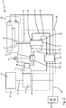
- FIG. 1 shows a first embodiment of a fluid system 1, which is part of a work machine, not shown, and which is designed for safe operation of a fluid-actuated actuator 2.
- the fluid system 1 comprises a control device 3, which is designed to provide control signals to a valve control 4 and to a working valve control 5.
- the valve control 4 is designed to control fluid control valves 6, 7.
- the working valve control 5 is designed to control working valves 8, 9.
- the working valves 8, 9 are coupled with a fluid source 10 as well as via fluid lines 11, 12 with the actuator 2. Accordingly, the working valves 8, 9 for influencing fluid flows between the fluid source 10 and the exemplary two, not shown working spaces of the actuator 2 are formed.
- an exemplary executed as an actuator of the actuator 2 piston rod 15 can be moved linearly between two unspecified end positions or optionally set in an intermediate position between the two end positions.
- the piston rod 15 is provided on the end with a punch 16, with which a workpiece 17 can be fixed to a table 18 in order to be able to carry out work operations not shown in more detail on the workpiece 17.
- the two fluid control valves 6, 7 are looped as shut-off valves in the fluid lines 11, 12 and can individually interrupt on request by the valve control fluid flow in the respective fluid line. In this way, a movement of the piston rod 15 of the actuator 2 can be prevented quickly.
- Two actuator as an end position switch, in particular as a Hall sensors, trained sensor means 19, 20 are arranged on the actuator 2, each output a sensor signal via a sensor line 21, 22 to a monitoring device 23, when the piston of the actuator 2 and not shown the piston rod 15 are located in one of the two linear end positions.
- the monitoring device 23 is connected via a signal line 24 to the valve control 4 and via a signal line 25 to a selector switch 28 designed for a mode of operation of the fluid system 1. Via the signal line 24, the monitoring device 23 can provide a monitoring signal to the valve control 4. Via the signal line 25, a selection signal from the operator switching means 28 can be provided to the monitoring device 23.
- the control device 3, the working valve control 5 and the working valves 8, 9 are in the present case designed according to a first safety category of a safety standard.
- the valve controller 4, the fluid control valves 6, 7, the sensor means 19, 20 and the monitoring device 23 form a safe working system 29, which are designed according to a second safety category of the safety standard. It is envisaged that the second safety category of the safe working system 29 within the safety standard at a higher level than the first safety category, which is provided for the control device 3, the working valve control 5 and the working valves 8, 9 is located. Accordingly, the safe working system 29 has a lower probability of failure than the control device 3.
- the monitoring device 23 is further coupled to a safety switching means in the form of a light grid 30, which is provided for securing a certain of the actuator 2, the piston rod 15 and the attached punch 16 and the table 18 hazardous area 31.
- the light grid 30 is designed such that, at least in the event that an unillustrated user or a workpiece 17 breaks through the light grid 30 during operation of the fluid system 1, it outputs a signal that can be processed by the monitoring device 23 and, if necessary, for Decommissioning of the actuator 2 leads.
- the light grid 30 serves as an access restriction in the form of access control.
- control device 3 outputs control signals to the working valve control 5 in order to effect a program-controlled actuation of the working valves 8, 9.
- control device 3 generates the control signals autonomously, that is, without requiring control commands from a higher-level machine control 32, if necessary, without being connected to the machine control 32.
- control device 3 can generate control signals, including control commands from the machine controller 32, with which the control device 3 is connected via a bus system 33, which enables bidirectional data exchange.
- the control of the working valves 8, 9 and thereby an admission of at least one of the fluid lines 11, 12 takes place with pressurized fluid.
- the pressurized fluid is thereby provided by the fluid source 10.
- an adjusting movement of the piston rod 15 of the actuator 2 between two end positions takes place by way of example, wherein in each of the two end positions the associated sensor means 19, 20 can transmit a sensor signal via the sensor lines 21, 22 to the monitoring device As soon as the not shown, connected to the piston rod 15 piston of the actuator 2 has reached the respective end position.
- An activation of the two fluid control valves 6, 7 by the valve control 4 can be provided if the fluid control valves 6, 7 are designed as normally closed (NC / normally closed) switching valves and none of the fluid flows through the fluid conduits 11, 12 of the Fluid control valves 6, 7 influenced, in particular blocked, to be. In this case, a blocking effect of the fluid control valves 6, 7 is achieved solely by switching off the control, whereby the fluid control valves 6, 7 reach the blocking position.
- the monitoring device 23 checks in knowledge of the control signals of the control device 3, whether the movement of the piston rod 15 of the actuator 2 takes place in accordance with the control signals provided. For this purpose, the monitoring device 23 checks whether the sensor signals of the two sensor means 19, 20 change within specifiable periods of time in the manner as is to be expected on the basis of the control signals. Furthermore, the monitoring device 23 checks whether the light grid 30 outputs a signal which indicates an opening of the light grid 30 by a user or a workpiece 17. If the change of the sensor signals of the sensor means. 19, 20 occurs within the predetermined time intervals and no signal from the light grid 30 is present, the monitoring device 23 determines a regular operation of the fluid system 1 and optionally outputs no monitoring signal or the normal operation of the fluid system 1 indicating monitoring signal to the valve control 4.
- the monitoring device 23 may output a monitoring signal to the valve controller 4, which is directed to the fact that an irregularity in the operation of the fluid system 1 is present.
- the monitoring device 23 may be set up such that it immediately outputs such a monitoring signal to the valve control 4 when irregularities in the fluid system 1 occur.
- the monitoring device 23 may be set up to output a monitoring signal to the valve control unit 4 only if a movement of the actuator 2 occurs at the time of determining an irregularity by the monitoring device 23 or if a movement of the actuator 2 is provided within a predefinable time segment ,
- valve control 4 Upon the arrival of a monitoring signal in the valve control 4, the valve control 4 can provide switching-off commands to the fluid control valves 6, 7 via control lines 34, 35. The fluid control valves 6, 7 then perform a blocking of the respective fluid line 11, 12 immediately after the arrival of the respective shutdown command. In this case, optionally, in particular depending on the mode of operation of the actuator 2, either the complete blockage of the fluid lines 11, 12 are provided by the valve control 4 or there is only the blocking of one of the fluid lines 11 or 12. Alternatively, a partial blockage, which is a Force limitation of the actuator has the consequence.
- the fastest and safest possible change of a movement state of the actuator 2 is achieved in order, for example, if a user interferes with the danger zone 31, a risk of injury from the actuator 2 and the components 16 operatively connected thereto To reduce 18.
- the monitoring signal from the monitoring device 23 is provided in parallel to the valve control 4 and to the control device 3, as indicated by the additional line branch 36 in the FIG. 1 is shown. It can be provided that, in the event of irregularities in the fluid system 1 and a corresponding output of a monitoring signal by the monitoring device 23 first in the control device 3 control signals are generated, which are to serve as a counter-reaction to the detected irregularity and which are transmitted via the working valve control 5 to the working valves 8, 9, for example, to cause a rapid interruption of movement of the actuator 2.
- the fluid system 1 serve the fluid control valves 6, 7 so only the change in the flow behavior, in particular the blocking of the fluid lines 11, 12 and this only if 1 irregularities are detected by the monitoring device 23 during operation of the fluid system.
- FIG. 2 illustrated embodiment of a fluid system 101 functionally identical components are provided with the same reference numerals as in the FIG. 1 , Notwithstanding the embodiment according to the FIG. 1 are in the embodiment of the fluid system 101 according to the FIG. 2 the fluid control valves 106, 107 are looped as the only valves in the respective fluid lines 111, 112 and communicate with the fluid source 10 in a communicating connection.
- control device 3 in the second embodiment of the in the FIG. 2 illustrated fluid system 101 as in the first embodiment of the in the FIG. 1 illustrated fluid system 1 according to a first safety category of a safety standard.
- the valve control 4, the fluid control valves 106, 107, the sensor means 19, 20 and the monitoring device 23 form in analogy to first embodiment according to FIG. 1 in the second embodiment according to FIG. 2 a secure work system 129, which is designed according to a second security category of the security standard, which is located at a higher level than the security category of the control device 3.
- the fluid control valves 106, 107 are used in a dual function, since they serve both in the regular operation of the fluid system 101 and in the occurrence of irregularities in the fluid system 101 for influencing the fluid flows through the fluid conduits 111, 112.
- this dual function of the fluid control valves 106, 107 can be dispensed with the working valves and the working valve control.
- this also considerably higher demands on the fluid control valves 106, 107 to make so that they still have to meet the requirements of those safety category, in which the components of the safe working system 129 are classified, and thus at. Due to the much higher load cycles in normal operation of the fluid system the construction and in the production of higher costs.
- the monitoring device is able to diagnose the correct function of the valve control and of the fluid control valves, which is also advantageous for the classification into a safety category.
- the fluid system 1 and the fluid system 101 can each be equipped with a higher-level safety circuit 37, which stands by way of example in communicating connection with the machine control 32 and with the monitoring device 23.
- the task of the safety circuit 37 is to monitor safety-relevant processes in the respective fluid system 1, 101, in particular by utilizing the sensor signals present at the monitoring device 23.
- the security circuit 37 can be set up, for example be to provide an enable signal to the monitoring device 23, if due to the received sensor signals and the control signals provided by the control device 3 and / or by the machine control 32, there is an uncritical state of the fluid system 1 or 101, in which, for example, an intervention A user can be accepted into the hazard area 31, since anyway no movement of the actuator 2 takes place or imminent.
- the output of a monitoring signal from the monitoring device 23 to the valve control 4 can be avoided in order to prevent a possible unfavorable influence on the fluid system 1 or 101, if the user intervention takes place at an uncritical time.
- an optional functional state is sought for a shutdown of the actuator 2 and a transfer of the actuator in a safe state of the fluid supply to avoid a sometimes unfavorable complete shutdown of the respective actuator 2 and consequential damage
- a sequence of several base states is provided for a shutdown of the actuator 2 or a transfer of the actuator to a safe state.
Description
Die Erfindung betrifft ein Fluidsystem zum sicheren Betreiben eines fluidisch ansteuerbaren Aktors, mit einer Steuereinrichtung zur Bereitstellung von Steuersignalen an eine Ventilsteuerung, mit einer Ventilsteuerung zur Ansteuerung von Fluidsteuerventilen, mit Fluidsteuerventilen, die elektrisch mit der Ventilsteuerung verbunden sind und die zur Beeinflussung von Fluidströmen an wenigstens einen Aktor ausgebildet sind, mit Sensormitteln, die zur Ermittlung eines Aktorzustands, insbesondere einer Aktorstellung, und zur Ausgabe von Sensorsignalen entsprechend dem ermittelten Aktorzustand ausgebildet sind, sowie mit einer Überwachungseinrichtung, die zur Verarbeitung der Sensorsignale und zur Bereitstellung eines Überwachungssignals an die Ventilsteuerung ausgebildet ist.The invention relates to a fluid system for safe operation of a fluid-actuated actuator, with a control device for providing control signals to a valve control, with a valve control for controlling fluid control valves, with fluid control valves, which are electrically connected to the valve control and which are used to influence fluid flows at least an actuator are formed, with sensor means which are designed to determine an actuator state, in particular an actuator position, and for output of sensor signals in accordance with the determined actuator state, and with a monitoring device which is designed for processing the sensor signals and for providing a monitoring signal to the valve control ,
Aus der
Aus der
Die
Die Aufgabe der Erfindung besteht darin, ein Fluidsystem sowie ein Verfahren zum Betreiben eines Fluidsystems bereitzustellen, die einen vorteilhaften Kompromiss zwischen einer Erfüllung hoher Sicherheitsanforderungen und einem unterbrechungsfreien Betrieb gewährleisten.The object of the invention is to provide a fluid system and a method for operating a fluid system, which ensure an advantageous compromise between meeting high security requirements and uninterrupted operation.
Diese Aufgabe wird für ein Fluidsystem der eingangs genannten Art mit den Merkmalen des Anspruchs 1 gelöst. Hierbei ist vorgesehen, dass die Steuereinrichtung gemäß einer ersten Sicherheitskategorie eines Sicherheitsstandards ausgebildet ist und dass die Ventilsteuerung, die Fluidsteuerventile, die Sensormittel und die Überwachungseinrichtung ein sicheres Arbeitssystem bilden und gemäß einer zweiten Sicherheitskategorie des Sicherheitsstandards ausgebildet sind, wobei die zweite Sicherheitskategorie auf einem höheren Niveau als die erste Sicherheitskategorie innerhalb des Sicherheitsstandards angesiedelt ist.This object is achieved for a fluid system of the type mentioned with the features of claim 1. Here is provided that the control device is designed according to a first safety category of a safety standard, and that the valve control, the fluid control valves, the sensor means and the monitoring device form a safe working system and are designed according to a second safety category of the safety standard, the second safety category being at a higher level than the safety category first safety category is located within the safety standard.
Als Sicherheitsstandards stehen beispielsweise nationale oder internationale Normen zur Verfügung, in denen beispielsweise die Anforderungen an die Zuverlässigkeit und/oder an ein definiertes Verhalten der jeweiligen Komponenten im Fehlerfall festgelegt sind und in denen die Betriebssicherheit bzw. Ausfallsicherheit der Komponenten üblicherweise in klar voneinander abgrenzbaren Sicherheitsklassen oder Sicherheitskategorien eingeordnet ist. Typischerweise muss eine Komponente, die einer bestimmten Sicherheitskategorie eines Sicherheitsstandards zugeordnet werden soll, durch den Hersteller und/oder durch ein unabhängiges Prüfinstitut daraufhin untersucht und gegebenenfalls zertifiziert werden, ob sie sämtliche Anforderungen der jeweiligen Sicherheitskategorie erfüllt.As safety standards, for example, national or international standards are available in which, for example, the requirements for reliability and / or a defined behavior of the respective components are defined in case of failure and in which the reliability or reliability of the components usually in clearly distinguishable safety classes or Safety categories is arranged. Typically, a component that is to be assigned to a certain safety category of a safety standard must then be examined by the manufacturer and / or by an independent testing institute and, if necessary, certified to fulfill all the requirements of the respective safety category.
Die Auslegung von Komponenten eines Fluidsystems auf die Anforderungen der jeweils angestrebten Sicherheitskategorie kann bei der Konstruktion, bei der Herstellung und gegebenenfalls auch bei der Integration der Komponenten in das jeweilige Arbeitssystem einen erheblichen Aufwand bedeuten und damit die Herstellungskosten für das jeweilige Fluidsystem beeinträchtigen. Somit ist es zweckmäßig, eine möglichst geringe Zahl von Komponenten des Fluidsystems gemäß einer hohen Sicherheitskategorie eines Sicherheitsstandards auszubilden, während die übrigen Komponenten des Fluidsystems gemäß niedrigeren Sicherheitskategorien ausgebildet sind. Praktisch kann dies beispielsweise bedeuten, dass die Komponenten, die der höheren Sicherheitskategorie zuzurechnen sind, eine geringere Ausfallwahrscheinlichkeit aufweisen als die Komponenten, die der niedrigeren Sicherheitskategorie zuzurechnen sind.The design of components of a fluid system to the requirements of the respective desired safety category can mean a considerable effort in the construction, in the manufacture and possibly also in the integration of the components in the respective work system and thus affect the manufacturing costs for the respective fluid system. Thus, it is desirable to form as few components of the fluid system as possible according to a high safety category of a safety standard, while the other components of the fluid system are designed according to lower safety categories. Practically For example, this may mean that the components attributable to the higher safety category are less likely to fail than the components that fall into the lower safety category.
Erfindungsgemäß ist die Systemgrenze für das sichere Arbeitssystem um die Gruppe von Komponenten des Fluidsystems, die gemäß einer gemeinsamen, hohen Sicherheitskategorie ausgebildet sind, eng gezogen, um die Anzahl der Komponenten im sicheren Arbeitssystem und damit die Kosten für das sichere Arbeitssystem gering zu halten.According to the invention, the system boundary for the safe working system around the group of components of the fluid system, which are designed according to a common, high safety category, is closely drawn in order to minimize the number of components in the safe working system and thus the costs for the safe working system.
Erfindungsgemäß ist die Steuereinrichtung, die die Abläufe innerhalb des Fluidsystems steuert und gegebenenfalls zumindest teilweise regelt und die einen komplexen Aufbau aufweist, nicht Bestandteil des sicheren Arbeitssystems, da jede Auslegung einer Steuereinrichtung auf die jeweils nächsthöhere Sicherheitskategorie einen erheblichen Mehraufwand bedeutet. Vielmehr sind bei den erfindungsgemäßen Fluidsystem nur diejenigen Komponenten der gegenüber der Steuereinrichtung höheren Sicherheitskategorie zugeordnet, die unmittelbar mit der Beeinflussung der Fluidzufuhr an den Aktor befasst sind oder die zur Überwachung der für die Fluidzufuhr notwendigen Komponenten vorgesehen sind, also insbesondere die Überwachungseinrichtung.According to the invention, the control device which controls and optionally at least partially controls the processes within the fluid system and which has a complex structure, is not part of the safe work system, since each design of a control device to the next higher security category means a significant overhead. Rather, in the case of the fluid system according to the invention, only those components of the higher safety category are assigned to the control device, which are directly concerned with influencing the fluid supply to the actuator or which are provided for monitoring the components required for the fluid supply, ie in particular the monitoring device.
Mit Hilfe des sicheren Arbeitssystems, das die Komponenten Ventilsteuerung, Fluidsteuerventile, Sensormittel und Überwachungseinrichtung umfasst, kann beispielsweise ein als fluidischer Arbeitszylinder ausgebildeter Aktor sicher angesteuert und dabei überwacht werden. Bei einer exemplarischen Betriebsweise für den Arbeitszylinder, bei der dieser durch entsprechende Beaufschlagung mit druckbeaufschlagtem Fluid beispielsweise zwischen einer Einfahrposition für die Kolbenstange und einer Ausfahrposition für die Kolbenstange geschaltet wird, sind die Sensormittel als Endlagenschalter ausgebildet, die jeweils ein Sensorsignal abgeben, wenn die Kolbenstange des Aktors eine der zwei jeweils vorgegebenen Endpositionen erreicht hat. Bleibt das Sensorsignal nach Bereitstellung von fluidischer Energie an den Aktor aus oder werden zeitgleich von beiden Sensormitteln Sensorsignale ausgegeben, wird von der Überwachungseinrichtung angesichts eines vermuteten Fehlerfalls ein Überwachungssignal an die Ventilsteuerung übermittelt. Die Ventilsteuerung steuert dann die Fluidsteuerventile derart an, dass der Aktor und die damit bewegungsgekoppelten Maschinenelemente in möglichst kurzer Zeit in einen sicheren Zustand gebracht werden können. Üblicherweise wird als sicherer Zustand eine möglichst rasche Abbremsung und Stilllegung des Aktors angestrebt, um eine einen Schaden an dem Fluidsystem und der Arbeitsmaschine, in die das Fluidsystem integriert ist, sowie eventuell eine Verletzungsgefahr für den Bediener der Arbeitsmaschine durch den Aktor und die damit bewegungsgekoppelten Maschinenelemente zu minimieren.With the help of the safe working system, which includes the components valve control, fluid control valves, sensor means and monitoring device, for example, designed as a fluidic cylinder actuator can be safely controlled and thereby monitored. In an exemplary operation for the working cylinder, in which this switched by appropriate application of pressurized fluid, for example between a retraction position for the piston rod and an extended position for the piston rod is, the sensor means are designed as limit switches, each emit a sensor signal when the piston rod of the actuator has reached one of the two predetermined end positions. If the sensor signal remains after provision of fluidic energy to the actuator or if sensor signals are emitted simultaneously by both sensor means, a monitoring signal is transmitted to the valve control by the monitoring device in the face of a presumed fault. The valve control then controls the fluid control valves in such a way that the actuator and the motion-coupled machine elements can be brought into a safe state in the shortest possible time. Usually, as fast as possible the fastest possible deceleration and decommissioning of the actuator is sought to avoid damage to the fluid system and the work machine into which the fluid system is integrated, as well as possibly a risk of injury to the operator of the work machine by the actuator and the motion-coupled machine elements to minimize.
Vorteilhafte Weiterbildungen der Erfindung sind Gegenstand der Unteransprüche.Advantageous developments of the invention are the subject of the dependent claims.
Zweckmäßig ist es, wenn das Arbeitssystem und die Steuereinrichtung gemäß den Sicherheitskategorien aus wenigstens einem der Sicherheitsstandards IEC 61508, IEC 61511, IEC 62061, IEC 13849 ausgebildet sind.It is expedient if the operating system and the control device are designed according to the safety categories from at least one of the safety standards IEC 61508, IEC 61511, IEC 62061, IEC 13849.
Bei einer vorteilhaften Weiterbildung der Erfindung ist vorgesehen, dass die Überwachungseinrichtung elektrisch mit einem Sicherheitsschaltmittel verbunden ist und für eine Einbeziehung eines Sicherheitssignals des Sicherheitsschaltmittels in das Überwachungssignal ausgebildet ist, wobei das Sicherheitsschaltmittel als Zugangsbegrenzung und/oder Zugangsüberwachung zu einem vom Aktor bestimmten Gefährdungsbereich, insbesondere als Lichtgitter oder als Trittschaltmatte oder als Türkontakt einer Wartungstür in einem Sicherheitskäfig, ausgebildet ist. Mit Hilfe eines derartigen Sicherheitsschaltmittels wird angestrebt, dass bei einem Eingreifen oder Eintreten eines Benutzers in den vom Aktor bestimmten Gefährdungsbereich eine Abschaltung des Fluidsystems und damit eines Aktors, der beispielsweise einer Arbeitsmaschine integriert ist, erfolgt.In an advantageous embodiment of the invention, it is provided that the monitoring device is electrically connected to a safety switching means and is designed for incorporation of a safety signal of the safety switching means in the monitoring signal, wherein the safety switching means as access control and / or access control to a specific danger area determined by the actuator, in particular as Light curtain or as a step mat or as a door contact a maintenance door in a safety cage, is formed. With the help of such a safety switching means is sought that when intervention or entry of a user in the risk area determined by the actuator, a shutdown of the fluid system and thus an actuator that is integrated, for example, a work machine, takes place.
Vorzugsweise ist die Überwachungseinrichtung elektrisch mit einem Bedienerschaltmittel und/oder mit einer Sicherheitsschaltung verbunden und ist für eine Einbeziehung eines Bediensignals des Bedienerschaltmittels und/oder eines Freigabesignals der Sicherheitsschaltung in das Überwachungssignal ausgebildet, wobei das Bedienerschaltmittel als Wahlschalter für eine Betriebsart des Fluidsystems ausgebildet ist und wobei die Sicherheitsschaltung als Überwachungssystem für das Fluidsystem ausgebildet ist. Exemplarisch kann vorgesehen sein, dass mit dem Bedienerschaltmittel das Fluidsystem für den Aktor aus einem Arbeitszustand in einen Ruhezustand oder aus einem Ruhezustand in einen Arbeitszustand versetzt werden kann. Bei einer Umschaltung des Fluidsystems aus dem Arbeitszustand in den Ruhezustand kann vorgesehen werden, dass das Bedienerschaltmittel ein diesem Benutzerwunsch entsprechendes Bediensignal an die Überwachungseinrichtung bereitstellt und die Überwachungseinrichtung auf dieses Bediensignal hin ein entsprechendes Überwachungssignal an die Ventilsteuerung ausgibt. Vorzugsweise ist die Ventilsteuerung so ausgebildet, dass sie eine situationsabhängige Abschaltung des Fluidsystems durchführen kann. Sofern die Ventilsteuerung ein Überwachungssignal erhält, das auf ein Bediensignal zurückgeht, mit dem der Benutzer eine Stilllegung der Arbeitsmaschine beispielsweise für Wartungszwecke anstrebt, kann vorgesehen sein, eine Beeinflussung der Fluidzufuhr erst dann vorzunehmen, wenn der Aktor ohnehin eine Vorzugsstellung erreicht hat, aus der heraus eine Wiederinbetriebnahme der Arbeitsmaschine ohne Zusatzaufwand möglich ist. Erhält die Ventilsteuerung hingegen ein Überwachungssignal, das in Zusammenhang mit einer Fehlfunktion der Sensormittel steht oder das von einem umgangssprachlich auch als Notaus-Schalter bezeichneten, als Nothalt-Schalter ausgebildeten Bedienerschaltmittel stammt, ist eine möglichst rasche Unterbrechung einer Bewegung des Aktors sowie dessen schnelle Stilllegung gewünscht und es erfolgt eine unmittelbare Einflussnahme auf die Fluidsteuerventile und die von diesen kontrollierten Fluidströme zum Aktor. Ergänzend oder alternativ kann die Überwachungseinrichtung mit einer Sicherheitsschaltung verbunden sein, die zur Bewertung eines Gefährdungspotentials des Fluidsystems ausgebildet ist und die ein Freigabesignal ausgibt, wenn das Gefährdungspotential des Fluidsystems unterhalb eines vorgebbaren Grenzwerts liegt. Dieses Freigabesignal wird von der Überwachungseinrichtung derart mit einbezogen, dass es zumindest für den Fall, dass ein Eingriff eines Benutzers in den vom Aktor bestimmten Gefährdungsbereich zumindest dann nicht zu einer Weiterleitung eines Überwachungssignals führt, wenn keine Bewegung des Aktors stattfindet und/oder in Kürze vorgesehen ist. Somit wird vermieden, dass möglicherweise durch ein entsprechendes Überwachungssignal das Fluidsystem ohne entsprechende Notwendigkeit in einen sicheren Zustand gebracht wird, aus dem es möglicherweise nur mit einem größeren Aufwand wieder in einen Normalzustand versetzt werden kann.Preferably, the monitoring device is electrically connected to a user switching means and / or with a safety circuit and is designed for inclusion of an operating signal of the user switching means and / or a release signal of the safety circuit in the monitoring signal, wherein the operator switching means is designed as a selector switch for a mode of the fluid system and wherein the safety circuit is designed as a monitoring system for the fluid system. By way of example, it can be provided that with the operator switching means, the fluid system for the actuator can be moved from a working state into an idle state or from a rest state into a working state. When switching the fluid system from the working state to the idle state, it can be provided that the user switching means provides an operating signal corresponding to this user request to the monitoring device and the monitoring device outputs a corresponding monitoring signal to the valve control in response to this operating signal. Preferably, the valve controller is designed so that it can perform a situation-dependent shutdown of the fluid system. If the valve control receives a monitoring signal, which goes back to an operating signal with which the user is seeking a shutdown of the machine, for example, for maintenance purposes, can be provided to make an impact on the fluid supply only when the actuator has already reached a preferred position, out of the a restart of the work machine without additional effort is possible. If, on the other hand, the valve control receives a monitoring signal which is related to a malfunction of the sensor means or which originates from a user switching means designated colloquially as an emergency stop switch, designed as an emergency stop switch, the fastest possible interruption of a movement of the actuator and its rapid decommissioning is desired and there is an immediate influence on the fluid control valves and the fluid flows controlled by them to the actuator. Additionally or alternatively, the monitoring device may be connected to a safety circuit, which is designed to evaluate a hazard potential of the fluid system and which outputs an enable signal when the hazard potential of the fluid system is below a predefinable limit value. This release signal is included by the monitoring device in such a way that, at least in the event that an intervention by a user in the hazard area determined by the actuator does not lead to a forwarding of a monitoring signal, if no movement of the actuator takes place and / or provided shortly is. Thus, it is avoided that may be brought by a corresponding monitoring signal, the fluid system without appropriate need in a safe state, from which it may possibly be put back into a normal state only with great effort.
Bei einer vorteilhaften Weiterbildung der Erfindung ist vorgesehen, dass die Ventilsteuerung oder das sichere Arbeitssystem dazu eingerichtet ist, die Fluidsteuerventile derart anzusteuern, dass Fluidströme an den wenigstens einen Aktor derart beeinflusst werden, dass der Aktor innerhalb einer vorgebbaren Zeitspanne in wenigstens einen vorgebbaren Funktionszustand aus der Gruppe: Aktor druckfrei; Fluidströme vom und/oder zum Aktor gestoppt; Bewegungsrichtungsvorgabe für Aktor; Aktor auf Stillstand geregelt; Aktor auf Vorgegebene Kraft geregelt; Druck im Aktor ungeregelt begrenzt; Aktorklemmung aktiviert; Bewegungsgeschwindigkeit des Aktors begrenzt; bringbar ist. Dabei können die Ventilsteuerung bzw. das sichere Arbeitssystem derart ausgebildet sein, dass sie nur einen Teil der Funktionszustände oder sämtliche Funktionszustände bewirken können, dies kann gegebenenfalls vom Benutzer durch entsprechende Parametrierung oder Programmierung der Ventilsteuerung bzw. des sicheren Arbeitssystems und/oder durch geeignete Auswahl der Ventilbauart vorgegeben werden. Dabei können die Ventilsteuerung bzw. das sichere Arbeitssystem derart konfiguriert werden, dass sie in Abhängigkeit von einem Überwachungssignal des Überwachungssystems und/oder bei Vorliegen eines Bediensignals eines Bedienerschaltmittels und/oder eines Freigabesignals einer Sicherheitsschaltung entsprechend einer gespeicherten Vorlage einen jeweiligen Funktionszustand bewirken. Die Auswahl des geeigneten Funktionszustands kann beispielsweise davon abhängig gemacht werden, ob sich aus den Überwachungssignalen, Freigabesignalen, Bediensignalen das Vorliegen eines mehr oder weniger kritischen Betriebszustands für das Fluidsystem ermitteln lässt, um in Abhängigkeit von der Schwere der ermittelten Störung eine geeignete Maßnahmen treffen, mit der die Störung möglichst folgenlos abgefangen werden kann.In an advantageous embodiment of the invention, it is provided that the valve control or the safe working system is adapted to control the fluid control valves such that fluid flows are influenced to the at least one actuator such that the actuator within a predetermined period of time in at least one predetermined functional state of the Group: Actuator pressure-free; Fluid flows from and / or to the actuator stopped; Movement direction preset for actuator; Actuator regulated to standstill; Actuator regulated to specified force; Pressure in actuator unregulated limited; Actuator clamping activated; Movement speed of the actuator limited; can be brought. In this case, the valve control or the safe working system can be designed such that they can cause only a portion of the functional states or all functional states, this may optionally by the user by appropriate parameterization or programming of the valve control or safe working system and / or by appropriate selection of Valve type can be specified. In this case, the valve control or the safe working system can be configured such that they effect a respective functional state as a function of a monitoring signal of the monitoring system and / or in the presence of an operating signal of an operator switching means and / or a release signal of a safety circuit according to a stored template. The selection of the suitable functional state can, for example, be made dependent on whether the monitoring signals, release signals, operating signals can be used to determine the presence of a more or less critical operating state for the fluid system, in order to take appropriate measures depending on the severity of the determined fault the disturbance can be intercepted without consequences.
Der Funktionszustand "Aktor druckfrei" für den Aktor ist ein Basiszustand und bedeutet, dass der fluidische Aktor keine Druckbeaufschlagung mehr aufweist. Dieser Zustand wird in Anlehnung an eine Abtrennung eines elektrischen Antriebs von einer elektrischen Versorgungsspannung als "safe torque off" oder "STO" bezeichnet.The functional state "actuator pressure-free" for the actuator is a base state and means that the fluidic actuator has no more pressurization. This state is referred to as a "safe torque off" or "STO" based on a separation of an electric drive from an electrical supply voltage.
Der Funktionszustand "Fluidströme vom und/oder zum Aktor gestoppt" für den Aktor ist ein Basiszustand und bedeutet, dass der Aktor innerhalb einer vorgegebenen Zeitspanne zum Stillstand kommt. Dabei ist bei entsprechender Konstruktionsweise des Aktors vorgesehen, dass durch das Schließen der Fluidsteuerventile im Aktor wenigstens eine Fluidmenge eingeschlossen wird, insbesondere alle Fluidmengen eingeschlossen werden, so dass eine Bewegung des Aktors zum Stillstand kommt und der Aktor eine Stillstandsposition hält. Dies ist beispielsweise bei einem Fluidzylinder mit zwei getrennten und von den Fluidsteuerventilen fluiddicht abgeschlossenen Arbeitsräumen der Fall. Dieser Zustand wird auch als Safe operation stop" oder "SOS" bezeichnet.The functional state "fluid flows from and / or to the actuator stopped" for the actuator is a base state and means that the actuator comes to a standstill within a predetermined period of time. It is with appropriate construction the actuator provided that by closing the fluid control valves in the actuator at least one fluid quantity is included, in particular all fluid quantities are included, so that a movement of the actuator comes to a standstill and the actuator holds a standstill position. This is the case, for example, in the case of a fluid cylinder with two separate work spaces which are closed in a fluid-tight manner by the fluid control valves. This condition is also referred to as safe operation stop "or" SOS ".
Der Funktionszustand "Bewegungsrichtungsvorgabe" für den Aktor ist ein Basiszustand und bedeutet, dass eine Fluidzufuhr an den Aktor derart vorgesehen oder aufrechterhalten wird, dass der Aktor eine Stellbewegung in eine vorgebbare Stellrichtung vollzieht, beispielsweise eine Rückzugs- oder Freigabebewegung, wie sie bei einer mit dem Aktor angetriebenen Klemmeinrichtung zur Vermeidung einer Unfallgefahr sinnvoll sein kann. Beispielsweise erfolgt bei einem Fluidzylinder mit zwei getrennten und von den Fluidsteuerventilen fluiddicht abschließbaren Arbeitsräumen zur Einnahme des Funktionszustands "Bewegungsrichtungsvorgabe" eine Aufnahme oder Weiterführung einer Fluidzufuhr in einen der Arbeitsräume, während das Fluid aus dem zweiten Arbeitsraum mittels der zugeordneten Fluidsteuerventile abgeführt wird. Durch die hieraus resultierende Druckdifferenz entsteht eine eindeutige Bewegungsrichtungsvorgabe. Dieser Funktionszustand wird auch als "Safe direction" oder "SDI" bezeichnet.The functional state "movement direction specification" for the actuator is a basic state and means that a fluid supply to the actuator is provided or maintained such that the actuator performs an actuating movement in a predeterminable adjustment direction, for example, a retraction or release movement, as in one with the Actuator driven clamping device to avoid an accident hazard can be useful. For example, in the case of a fluid cylinder with two separate working spaces that are fluid-tightly lockable by the fluid control valves for receiving the functional state "movement direction specification", a fluid supply is received or continued in one of the working spaces, while the fluid is removed from the second working chamber by means of the associated fluid control valves. The resulting pressure difference creates a clear direction of motion. This functional state is also referred to as "safe direction" or "SDI".
Der Funktionszustand "Aktor auf Stillstand geregelt" ist ein optionaler Funktionszustand und bedeutet, dass der Aktor eine vorgebbare Position einnimmt und hält. Beispielsweise kann vorgesehen sein, dass der Aktor hierzu aus einer Bewegung abgebremst wird und bei Erreichen des Stillstands in der Stillstandsposition gehalten wird. Alternativ kann vorgesehen sein, dass der Aktor aus dem Stillstand oder aus einer Bewegung in eine vorgegebene Position verfahren wird. Dieser Funktionszustand wird auch als "Safe balanced torque" oder "SBT" bezeichnet. Sofern sich dieser Funktionszustand nicht innerhalb einer vorgebbaren Zeitspanne einstellen lässt, wird der Aktor in einen der Basiszustände, insbesondere in den Funktionszustand "Aktor druckfrei" überführt.The "Actuator controlled to standstill" functional state is an optional functional state and means that the actuator assumes and holds a predefinable position. For example, it can be provided that the actuator is braked for this purpose from a movement and is held in the standstill position when it reaches standstill. Alternatively it can be provided that the actuator from a standstill or from a movement is moved in a predetermined position. This functional state is also referred to as "safe balanced torque" or "SBT". If this functional state can not be set within a predefinable period of time, the actuator is transferred to one of the base states, in particular into the functional state "actuator pressure-free".
Der Funktionszustand "Aktor auf vorgegebene Kraft geregelt" ist ein optionaler Funktionszustand und bedeutet, dass der Druck in wenigstens einem Arbeitsraum des Aktors so geregelt wird, dass der Aktor eine auf ein vorgebbares Kraftniveau begrenzte Kraft oder ein vorgegebenes Moment abgeben kann. Dieser Funktionszustand wird auch als "Safe limited torque" oder "SLT" bezeichnet. Dieser Funktionszustand ist beispielsweise dann von Interesse, wenn der Aktor zur Bewegung eines Greifers oder einer Einspanneinrichtung dient und im Fehlerfall sichergestellt werden soll, dass ein zu diesem Zeitpunkt bereits gegriffener oder eingespannter Gegenstand nicht freigegeben wird, wie dies beispielsweise im Funktionszustand "Aktor druckfrei" der Fall wäre. Sofern sich der Funktionszustand "Aktor auf Vorgegebene Kraft geregelt" nicht innerhalb einer vorgebbaren Zeitspanne einstellen lässt, wird der Aktor in einen der Basiszustände, insbesondere in den Funktionszustand "Fluidströme vom und/oder zum Aktor gestoppt" überführt.The functional state "actuator controlled to predetermined force" is an optional functional state and means that the pressure in at least one working space of the actuator is controlled so that the actuator can deliver a limited force to a predetermined force level or a predetermined moment. This functional state is also referred to as "Safe limited torque" or "SLT". This functional state is for example of interest when the actuator is used to move a gripper or a clamping device and to ensure in the event of an error that at this time already gripped or clamped object is not released, as for example in the functional state "actuator pressure-free" Case would be. If the function state "actuator controlled to predetermined force" can not be set within a predefinable period of time, the actuator is in one of the base states, in particular in the functional state "fluid flows from and / or to the actuator stopped" transferred.
Der Funktionszustand "Druck im Aktor ungeregelt begrenzt" ist ein optionaler Funktionszustand und bedeutet, dass eine Druckbeaufschlagung des Aktors auf einen vorgebebenen Druckwert erfolgt, ohne dass dieser Druckwert auf ein Vorliegen von Abweichungen hin überwacht wird oder eine Nachführung der Druckbeaufschlagung erfolgt. Dieser Funktionszustand wird auch als "Safe torque range" oder "SLR" bezeichnet. Sofern sich dieser Funktionszustand nicht innerhalb einer vorgebbaren Zeitspanne einstellen lässt, wird der Aktor in einen der Basiszustände, insbesondere in den Funktionszustand "Aktor druckfrei" überführt.The functional state "pressure in the actuator uncontrolled limited" is an optional functional state and means that the actuator is pressurized to a predetermined pressure value without this pressure value being monitored for the presence of deviations or that the pressurization is updated. This functional state is also referred to as "Safe torque range" or "SLR". If this functional state can not be set within a predefinable period of time, the actuator is placed in one of the Base states, especially in the functional state "actuator pressure-free" transferred.
Der Funktionszustand "Aktorklemmung aktiviert" ist ein optionaler Funktionszustand und bedeutet, dass eine dem Aktor zugeordnete Klemmung, beispielsweise eine durch Federkraft betätigte Bremse, welche pneumatisch oder elektromechanisch geöffnet wird, aktiviert wird, um eine Bewegung des Aktors abzubremsen und/oder um einen stillstehenden Aktor in seiner Stillstandsposition zu halten. Dies ist eine Ergänzung zum den Basiszustand "Aktor druckfrei".The functional state "Aktorklemmung activated" is an optional functional state and means that an actuator associated clamping, for example, a spring-actuated brake, which is pneumatically or electromechanically opened, is activated to decelerate movement of the actuator and / or a stationary actuator to hold in its stoppage position. This is a supplement to the basic state "actuator pressure-free".
Der Funktionszustand "Bewegungsgeschwindigkeit des Aktors begrenzt" ist ein optionaler Funktionszustand und bedeutet, dass der Aktor durch geeignete Ansteuerung der Fluidsteuerventile eine geschwindigkeitsbegrenzte Bewegung aufnimmt oder weiterführt. Dieser Funktionszustand wird auch als "Safe limited speed" oder "SLS" bezeichnet. Sofern sich dieser Funktionszustand nicht innerhalb einer vorgebbaren Zeitspanne einstellen lässt, wird der Aktor in einen der Basiszustände, insbesondere in den Funktionszustand "Aktor druckfrei" überführt.The functional state "movement speed of the actuator limited" is an optional functional state and means that the actuator adopts or continues a speed-limited movement by suitable activation of the fluid control valves. This functional state is also referred to as "Safe limited speed" or "SLS". If this functional state can not be set within a predefinable period of time, the actuator is transferred to one of the base states, in particular into the functional state "actuator pressure-free".
In weiterer Ausgestaltung der Erfindung ist vorgesehen, dass die Ventilsteuerung oder das sichere Arbeitssystem dazu eingerichtet ist, eine zeitliche Abfolge von wenigstens zwei Funktionszuständen vorzugeben. Dadurch kann erreicht werden, dass der Aktor zunächst eine Bewegung vollzieht oder weiterführt, um anschließend nach Erreichen einer vorgebbaren Position beispielsweise festgelegt zu werden.In a further embodiment of the invention, it is provided that the valve control or the safe working system is set up to specify a temporal sequence of at least two functional states. As a result, it can be achieved that the actuator first performs a movement or continues to be fixed, for example, after reaching a predefinable position.
Bei einer ersten Variante, die auch als "sicherer Halt / Typ 1" oder "safe stop 1" oder "SS1" bezeichnet wird, erfolgt zunächst eine Überführung des Aktors in den Funktionszustand "Fluidströme vom und/oder zum Aktor gestoppt" oder "SOS" bis der Aktor stillsteht, um dann in einem weiteren Schritt eine Überführung des Aktors in den Funktionszustand "Aktor drucklos" oder "STO" vorzunehmen.In a first variant, which is also referred to as "safe stop / type 1" or "safe stop 1" or "SS1", the actuator is first transferred to the functional state "fluid flows from and / or to the actuator stopped" or "SOS "until the actuator stops, then in another step one Transfer of the actuator to the functional state "Actuator depressurized" or "STO".
Bei einer zweiten Variante, die auch als "sichere Endposition" oder "safe end position" oder "SEP" bezeichnet wird, erfolgt zunächst eine Überführung des Aktors in den Funktionszustand "Bewegungsrichtungsvorgabe" oder "SDI", bis der Aktor eine Endlage erreicht hat, um dann in einem weiteren Schritt eine Überführung des Aktors in den Funktionszustand "Aktor drucklos" oder "STO" vorzunehmen.In a second variant, which is also referred to as "safe end position" or "safe end position" or "SEP", the actuator is first transferred to the functional state "movement direction specification" or "SDI" until the actuator has reached an end position. in order then to carry out a transfer of the actuator into the functional state "actuator depressurized" or "STO" in a further step.
Bei einer dritten Variante, die auch als "sichere Rückzugsposition" oder "safe retracting" oder "SRT" bezeichnet wird, erfolgt zunächst eine Überführung des Aktors in den Funktionszustand "Bewegungsrichtungsvorgabe" oder "SDI", bis der Aktor eine Rückzugsposition erreicht hat, um dann in einem weiteren Schritt eine Überführung des Aktors in den Funktionszustand "Fluidströme vom und/oder zum Aktor gestoppt" oder "SOS" vorzunehmen.In a third variant, which is also referred to as "safe retraction position" or "safe retracting" or "SRT", the actuator is first transferred to the functional state "movement direction specification" or "SDI" until the actuator has reached a retraction position then in a further step, a transfer of the actuator in the functional state "fluid flows from and / or to the actuator stopped" or "SOS" make.
Vorteilhaft ist es, wenn die Steuereinrichtung elektrisch mit dem Sicherheitsschaltmittel und/oder mit dem Bedienerschaltmittel verbunden ist und für eine Einbeziehung eines Signals des Sicherheitsschaltmittels und/oder des Bedienerschaltmittels bei der Erzeugung von Steuerbefehlen an Arbeitsventile, die mit dem Aktor verbunden sind und/oder an die Ventilsteuerung ausgebildet ist. Hierdurch erhält die Steuerungseinrichtung Informationen über erfolgte Eingriffe des Sicherheitsschaltmittels. Weiterhin kann hierdurch ein Eingreifen der Überwachungseinrichtung und der Ventilsteuerung je nach Arbeitssituation des Fluidsystems und des Aktors vermieden werden, das möglicherweise zu einem Stillstand des Aktors in einer ungünstigen Position führen könnte. Dieses Eingreifen der Überwachungseinrichtung und der Ventilsteuerung wird vorzugsweise dadurch verhindert, dass die Signale des Sicherheitsschaltmittels und/oder des Bedienerschaltmittels bereits bei der Erzeugung von Steuerbefehlen durch die Steuereinrichtung berücksichtigt werden und somit möglicherweise eine Ansteuerung des Aktors, die gemäß einem in der Steuereinrichtung gespeicherten Programm vorzunehmen wäre, nicht oder zu einem späteren Zeitpunkt erfolgt. Hierbei ist insbesondere von Bedeutung, dass die Steuereinrichtung möglicherweise zur Ansteuerung mehrerer Aktoren vorgesehen ist und bei Vorliegen eines Signals des Sicherheitsschaltmittels und/oder des Bedienerschaltmittels eine koordinierte Unterbrechung weiterer Bewegungsabläufe der Aktoren vorsehen kann.It is advantageous if the control device is electrically connected to the safety switching means and / or the operator switching means and for inclusion of a signal of the safety switching means and / or the operator switching means in the generation of control commands to working valves, which are connected to the actuator and / or to the valve control is formed. As a result, the control device receives information about past intervention of the safety switching means. Furthermore, an intervention of the monitoring device and the valve control can be avoided depending on the working situation of the fluid system and the actuator, which could possibly lead to a standstill of the actuator in an unfavorable position. This intervention of the monitoring device and the valve control is preferably prevented by the fact that the signals of the safety switching means and / or the user switching means already at the generation of control commands are taken into account by the control device and thus possibly a control of the actuator, which would be carried out according to a program stored in the control device, not or at a later time takes place. In this case, it is particularly important that the control device is possibly provided for controlling a plurality of actuators and can provide a coordinated interruption of further movement sequences of the actuators in the presence of a signal of the safety switching means and / or the operator switching means.
Bevorzugt sind die Fluidsteuerventile für eine Fluidsteuerung des Aktors als Schaltventile zwischen eine Fluidquelle und den Aktor einschleifbar oder sind stromauf oder stromab von Arbeitsventilen, die von der Steuereinrichtung ansteuerbar sind, als Sperrventile zwischen die Fluidquelle und den Aktor einschleifbar, um eine Stellbewegung eines Stellglieds des Aktors in eine vorgebbare Schaltstellung oder einen Verbleib des Stellglieds des Aktors in der vorgebbaren Schaltstellung zu gewährleisten.Preferably, the fluid control valves for fluid control of the actuator as a switching valves between a fluid source and the actuator are einschleifbar or upstream or downstream of working valves, which are controlled by the control device, as a check valves between the fluid source and the actuator einschleifbar to an actuating movement of an actuator of the actuator to ensure in a predetermined switching position or a whereabouts of the actuator of the actuator in the predetermined switching position.
Bei einer ersten Ausführungsform ist vorgesehen, dass ausschließlich Fluidsteuerventile für die Beeinflussung der Fluidströme zum Aktor während des Betriebszustands vorgesehen sind und entsprechend den Vorgaben der Steuereinrichtung und der nachgeschaltet angeordneten Ventilsteuerung zwischen unterschiedlichen Funktionsstellungen, insbesondere zwischen einer Öffnungsstellung und einer Schließstellung, geschaltet oder proportional zu Steuersignalen der Ventilsteuerung eingestellt werden. Da die Fluidsteuerventile bei dieser Ausführungsform während des normalen Betriebszustands des Fluidsystems eine große Anzahl von Lastspielen, also Schaltvorgängen zwischen den einzelnen Funktionsstellungen, vollziehen und über eine definierte, passive Vorzugslage verfügen, müssen sie hinsichtlich ihrer Auslegung hohe Anforderungen erfüllen, um die für das sichere Arbeitssystem geforderte Sicherheitskategorie zu erfüllen. Bei den Fluidsteuerventilen kann es sich somit je nach Anwendungsfall um Schaltventile, um Parallel- und/oder Reihenschaltungen von Schaltventilen mit identischen oder vorzugsweise unterschiedlichen Strömungswiderständen oder um Proportionalventile handeln.In a first embodiment, it is provided that only fluid control valves are provided for influencing the fluid flows to the actuator during the operating state and according to the specifications of the control device and the downstream arranged valve control between different functional positions, in particular between an open position and a closed position, switched or proportional to control signals the valve control can be adjusted. Since the fluid control valves in this embodiment during the normal operating state of the fluid system a large number of load cycles, ie switching operations between the individual functional positions, perform and have a defined, passive preferred position must they meet high requirements for their design in order to meet the safety category required for the safe working system. Depending on the application, the fluid control valves can thus be switching valves, parallel and / or series connections of switching valves with identical or preferably different flow resistances, or proportional valves.
Bei einer zweiten, alternativen Ausführungsform ist vorgesehen, dass die Fluidsteuerventile als Sperrventile eingesetzt werden, die zusätzlich zu Arbeitsventilen, die von der Steuereinrichtung, gegebenenfalls unter Zwischenschaltung einer Arbeitsventilsteuerung, angesteuert werden, in Fluidleitungen zwischen eine Fluidquelle und den Aktor einschleifbar sind. Dabei dienen die Fluidsteuerventile im Fehlerfall und/oder im Notfall nach Übermittlung eines Überwachungssignals von der Überwachungseinrichtung an die Ventilsteuerung zum Sperren der jeweiligen Fluidleitung. Bei dieser Ausführungsform können mehrere Vorteile zum Tragen kommen. Einerseits sind in jeder mit dem Aktor verbindbaren Fluidleitung wenigstens zwei Ventile, also insbesondere das Arbeitsventil und das Fluidsteuerventil, angeordnet, so dass die im Fehlerfall/Notfall notwendige Unterbrechung des Fluidstroms durch die jeweilige Fluidleitung redundant abgesichert ist. Zudem werden diese in die jeweilige Fluidleitung einschleifbaren Ventile von unterschiedlichen Einrichtungen, vorliegend von der Steuereinrichtung und von der Ventilsteuerung, angesteuert, so dass auch eine steuerungstechnische Redundanz vorliegt. Ferner müssen die als Sperrventile für Notfälle dienenden Fluidsteuerventile nur eine geringe Anzahl von Lastspielen mit der geforderten Zuverlässigkeit erfüllen können und sind damit mit einem geringeren Konstruktions- und Kostenaufwand in die gleiche Sicherheitskategorie wie die übrigen Komponenten des sicheren Arbeitssystems einzuordnen, als dies bei der vorstehend geschilderten ersten Ausführungsform der Fall ist. Bevorzugt ist die Steuereinrichtung für eine bidirektionale Kommunikation, insbesondere über ein Feldbussystem, mit einer übergeordneten Maschinen- oder Prozesssteuerung ausgebildet, die einer identischen oder niedrigeren oder höheren Sicherheitskategorie zuzurechnen ist wie die Steuereinrichtung. Die Maschinen- oder Prozesssteuerung ist für eine Koordination mehrerer Steuereinrichtungen ausgebildet und kommuniziert mit den Steuereinrichtungen über ein Feldbussystem. Gemäß einem zweiten Aspekt wird die Aufgabe der Erfindung mit einem Verfahren zum Betreiben eines Fluidsystems, das nach einem der Vorrichtungsansprüche ausgebildet ist, gemäß Anspruch 8 gelöst. Hierbei sind die folgenden Schritte vorgesehen: Ermitteln des Aktorzustands mit den Sensormitteln und Ausgeben von Sensorsignalen entsprechend dem ermittelten Aktorzustand an die Überwachungseinrichtung, Verarbeiten der Sensorsignale in der Überwachungseinrichtung und Bereitstellen eines Überwachungssignals an die Ventilsteuerung zumindest für die Fälle, dass keine Sensorsignale von den Sensormitteln bereitgestellt werden oder dass fehlerhafte Sensorsignale von den Sensormitteln bereitgestellt werden, Verarbeiten des Überwachungssignals in der Ventilsteuerung, insbesondere in Abhängigkeit von den ermittelten Sensorsignalen, und Ansteuern der Fluidsteuerventile zur Beeinflussung wenigstens eines Fluidstroms an den Aktor, so dass der Aktor einen vorgebbaren, sicheren Zustand einnimmt und/oder beibehält. Hierdurch werden in einer Art Grundfunktionalität des Fluidsystems zumindest die Fehlerfälle erkannt, die auf einer Fehlfunktion der Sensormittel oder auf einer Fehlfunktion des Aktors beruhen. Dabei wird von einer Fehlfunktion der Sensormittel ausgegangen, wenn Sensorsignale von den Sensormitteln in der Überwachungseinrichtung eintreffen, die nicht plausibel sind, beispielsweise ein zeitgleicher Eingang von Sensorsignalen zweier voneinander beabstandet angeordneter Endlagensensoren. Von einer Fehlfunktion der Sensormittel und/oder des Aktors wird ausgegangen, wenn nach Bereitstellung fluidischer Energie an den Aktor innerhalb eines vorgebbaren Zeitraums keine Änderung der Sensorsignale erfolgt oder nach einer anfänglichen Änderung der Sensorsignale innerhalb eines vorgebbaren Zeitraums keine weitere Änderung der Sensorsignale auftritt, wodurch normalerweise das Erreichen einer vorgegebenen Stellung durch den Aktor angezeigt würde. Für diese Fehlerfälle ist vorgesehen, keine weitere fluidische Energie an den Aktor bereitzustellen oder einen Fluidstrom an den Aktor zu unterbrechen, damit dieser entweder einen sicheren Zustand beibehält oder einen sicheren Zustand einnehmen kann.In a second, alternative embodiment it is provided that the fluid control valves are used as check valves, which in addition to working valves, which are controlled by the control device, optionally with the interposition of a working valve control, in fluid lines between a fluid source and the actuator are einschleifbar. In this case, the fluid control valves are used in the event of a fault and / or in an emergency after transmission of a monitoring signal from the monitoring device to the valve control for blocking the respective fluid line. In this embodiment, several advantages may come into play. On the one hand, at least two valves, that is to say in particular the working valve and the fluid control valve, are arranged in each fluid line which can be connected to the actuator, so that the interruption of the fluid flow necessary in the event of a fault / emergency is redundantly secured by the respective fluid line. In addition, these valves which can be grinded into the respective fluid line are actuated by different devices, in this case by the control device and by the valve control, so that there is also redundant control technology. Further, the fluid control valves serving as emergency shut-off valves need only be capable of satisfying a small number of load cycles with the required reliability, and thus with a lower design and cost in the same safety category as the other components of the safe Work system to classify, as is the case in the above-described first embodiment. The control device is preferably designed for bidirectional communication, in particular via a fieldbus system, with a higher-level machine or process control, which is attributable to an identical or lower or higher safety category as the control device. The machine or process control is designed for coordination of a plurality of control devices and communicates with the control devices via a fieldbus system. According to a second aspect, the object of the invention with a method for operating a fluid system, which is formed according to one of the device claims, according to
Bei einer Ausgestaltung des Verfahrens ist vorgesehen, dass die Überwachungseinrichtung elektrische Signale eines Sicherheitsschaltmittels überwacht und bei einem Eingriff oder Zutritt in einen vom Aktor bestimmten Gefährdungsbereich ein entsprechendes Überwachungssignal an die Ventilsteuerung bereitstellt, um die Fluidsteuerventile derart anzusteuern, dass wenigstens ein Fluidstrom an den Aktor derart beeinflusst wird, dass der Aktor einen vorgebbaren, sicheren Zustand einnimmt oder beibehält. Hierdurch wird eine Absicherung eines vom Aktor bestimmten Gefährdungsbereichs, also beispielsweise eines Schwenkbereichs oder eines linearen Verstellbereichs eines Maschinenelements, das mit dem Aktor bewegungsgekoppelt ist, mit Hilfe von Sicherheitsschaltmitteln wie Lichtgittern oder Trittschaltmatten erreicht. Bei einem Eingreifen oder Annähern eines Benutzers oder eines Gegenstands in den abgesicherten Gefährdungsbereich erfolgt aufgrund der dadurch ausgelösten elektrische Signale des Sicherheitsschaltmittels eine Unterbrechung der Zufuhr von fluidischer Energie an den Aktor. Gegebenenfalls kann zusätzlich eine aktive Klemmung des Aktors vorgesehen werden.In one embodiment of the method, it is provided that the monitoring device monitors electrical signals of a safety switching means and provides a corresponding monitoring signal to the valve control during an intervention or access to a risk area determined by the actuator, in order to control the fluid control valves such that at least one fluid flow to the actuator in such a way is influenced that the actuator assumes or maintains a predefinable, safe state. In this way, a safeguarding of a danger range determined by the actuator, that is to say, for example, a swiveling range or a linear displacement range of a machine element, which is motion-coupled to the actuator, is achieved with the aid of safety switching means, such as light grids or stepping mats. Upon intervention or approach of a user or an object in the protected hazardous area occurs due to the thereby triggered electrical signals of the safety switching means an interruption of the supply of fluidic energy to the actuator. Optionally, an active clamping of the actuator can be additionally provided.
Bei einer weiteren Ausgestaltung des Verfahrens ist vorgesehen, dass die Überwachungseinrichtung bei Detektion eines Eingriffs oder Zutritts in einen vom Aktor bestimmten Gefährdungsbereich anhand des Signals des Sicherheitsschaltmittels erst dann ein entsprechendes Überwachungssignal an die Ventilsteuerung bereitstellt, wenn eine bevorstehende Zustandsänderung des Aktors anhand einer Ausgabe eines Steuersignals der Steuereinrichtung und/oder der Ventilsteuerung ermittelt wird und/oder eine Zustandsänderung des Aktors anhand wenigstens einer Änderung eines Sensorsignals von wenigstens einem der Sensormittel erfasst wird. Hierdurch wird bei Fluidsystemen, bei denen der Aktor nur zeitweilig in Bewegung ist, eine Unterbrechung des Arbeitszustands zumindest dann vermieden, wenn der Eingriff oder Zutritt des Benutzers in einem Zeitabschnitt erfolgt, in dem keine Aktorbewegung unmittelbar, also innerhalb eines vorgebbaren Zeitabschnitts, bevorsteht oder stattfindet. Dadurch kann vermieden werden, dass eine Arbeitsmaschine, in die das Fluidsystem mit dem Aktor integriert ist, durch entsprechende Ansteuerung der Fluidsteuerventile unnötig in einen sicheren Zustand gebracht wird, aus dem sie möglicherweise nur unter Schwierigkeiten wie Zeitverlust im Fertigungsablauf und/oder Einbußen beim Materialfluss, wieder in den Arbeitszustand versetzt werden kann. Um diese Funktionsweise des Fluidsystems zu ermöglichen, sind wenigstens eine unidirektionale Kommunikation ausgehend von der Steuereinrichtung zur Überwachungseinrichtung oder eine bidirektionale Kommunikation zwischen der Überwachungseinrichtung und der Ventilsteuerung vorgesehen. In jedem Fall ist die Überwachungseinrichtung derart ausgebildet, dass sie anhand der Steuersignale für die Arbeitsventile und/oder für die Fluidsteuerventile auf eine Bewegung des Aktors zurückschließen kann und nur bei zeitgleichem Vorliegen einer Aktorbewegung und einem Signal des Sicherheitsschaltmittels, das einen Eingriff und/oder Zutritt eines Benutzers in den Gefährdungsraum angibt, ein entsprechendes Überwachungssignal an die Ventileinheit zur Ansteuerung der Fluidsteuerventile und damit zur Blockierung des Aktors ausgibt.In a further refinement of the method, it is provided that the monitoring device only provides a corresponding monitoring signal to the valve control upon detection of an intervention or access to a danger zone determined by the actuator on the basis of the signal of the safety switching means, if an impending state change of the actuator is based on an output of a control signal the control device and / or the valve control is determined and / or a change in state of the actuator is detected based on at least one change of a sensor signal from at least one of the sensor means. As a result, in fluid systems in which the actuator is only temporarily in motion, an interruption of the working state is at least avoided if the intervention or access of the user takes place in a period in which no actuator movement directly, ie within a predeterminable period, imminent or occurs , This can be avoided that a working machine, in which the fluid system is integrated with the actuator, is unnecessarily brought into a safe state by appropriate control of the fluid control valves from which they may be only with difficulty such as loss of time in the production process and / or loss of material flow, can be put back into the working state. In order to enable this mode of operation of the fluid system, at least one unidirectional communication is provided from the control device to the monitoring device or a bidirectional communication between the monitoring device and the valve control. In any case, the monitoring device is designed such that it can deduce the basis of the control signals for the working valves and / or for the fluid control valves on a movement of the actuator and only in the simultaneous presence of an actuator movement and outputs a signal of the safety switching means, which indicates an intervention and / or access of a user in the hazardous area, a corresponding monitoring signal to the valve unit for controlling the fluid control valves and thus to block the actuator.
Bei einer weiteren Ausgestaltung des Verfahrens ist vorgesehen, dass die Überwachungseinrichtung die Bereitstellung des Überwachungssignals einstellt, sobald keine Detektion eines Eingriffs oder Zutritts in einen vom Aktor bestimmten Gefährdungsbereich mehr vorliegt und dass die Ventilsteuerung ohne Vorliegen eines Überwachungssignals keine von einer Vorgabe durch die Steuereinrichtung abweichende Ansteuerung der Fluidsteuerventile vornimmt. Hierdurch wird ebenfalls eine unerwünschte Unterbrechung des Arbeitszustands des Fluidsystems verhindert.In a further embodiment of the method, it is provided that the monitoring device adjusts the provision of the monitoring signal as soon as there is no longer detection of an intervention or access in a hazardous area determined by the actuator and if the valve control does not deviate from a specification by the control device without the presence of a monitoring signal the fluid control valves makes. As a result, an undesirable interruption of the working state of the fluid system is also prevented.
Bei einer weiteren Ausgestaltung des Verfahrens ist vorgesehen, dass die Ventilsteuerung die Fluidsteuerventile derart ansteuert, dass wenigstens ein Arbeitsraum im Aktor während des Vorliegens eines entsprechenden Überwachungssignals mit druckbeaufschlagtem Fluid versorgt bleibt. Hierdurch kann je nach Art und Bauweise des Aktors ein vorteilhafter sicherer Ruhezustand für den Aktor erreicht werden, aus dem dieser problemlos, insbesondere sehr rasch und mit nur geringem Energieaufwand, wieder in den Arbeitszustand zurückversetzt werden kann. Beispielsweise kann ein als Fluidzylinder ausgebildeter Aktor im Falle des Auftretens eines Überwachungssignals und der daraus resultierenden Anforderung, möglichst schnell einen bewegungslosen Zustand einzunehmen, entweder vollständig entlüftet werden oder es ist vorgesehen, bei einem doppeltwirkenden Fluidzylinder wenigstens eine der Arbeitskammern oder beide der Arbeitskammern druckbelastet zu belassen. Hierdurch kann der Aktor sich in eine sichere Position bewegen, auch wenn die Fluidzufuhr aus nicht näher dargestellten Gründen unterbrochen ist. Vorzugsweise kann bei einer neuerlichen Inbetriebnahme des Fluidsystems allein durch Entlüften der einen Arbeitskammer eine Bewegung des Aktors hervorgerufen werden, ohne dass hierzu zwingend eine Fluidzufuhr zum Aktor notwendig ist.In a further embodiment of the method, it is provided that the valve control controls the fluid control valves such that at least one working space in the actuator remains supplied with pressurized fluid during the presence of a corresponding monitoring signal. As a result, depending on the type and construction of the actuator, an advantageous safe rest state for the actuator can be achieved, from which it can easily be returned to the working state, in particular very quickly and with only little expenditure of energy. For example, a trained as a fluid cylinder actuator in the event of the occurrence of a monitoring signal and the resulting requirement to take a motionless state as quickly as possible, either completely vented or it is intended to leave pressure loaded in a double-acting fluid cylinder at least one of the working chambers or both of the working chambers , This allows the actuator to move to a safe position, even if the fluid supply is interrupted for reasons not shown. Preferably, at a renewed startup of the fluid system alone by venting a working chamber, a movement of the actuator are caused, without necessarily a fluid supply to the actuator is necessary.
Bei einer weiteren Ausgestaltung des Verfahrens ist vorgesehen, dass die Überwachungseinrichtung elektrische Signale eines Bedienerschaltmittels überwacht und das Überwachungssignal an die Ventilsteuerung in Abhängigkeit von den ermittelten Signalen des Bedienerschaltmittels anpasst. Bei dem Bedienerschaltmittel kann es sich entweder um einen Wahlschalter für eine Betriebsart des Fluidsystems handeln, mit dem beispielsweise eine Anwahl eines Arbeitszustands, eines Wartungszustands und eines Ruhezustands vorgenommen wird, oder es handelt sich um einen Notaus- bzw. Nothalt-Schalter, der bei Betätigung durch den Benutzer eine möglichst rasche Stilllegung des Aktors und des damit gekoppelten Fluidsystems bewirken soll. Bei einer Ausbildung des Bedienerschaltmittels als Wahlschalter kann die Überwachungseinrichtung derart konfiguriert werden, dass der vom Benutzer angewählte Betriebszustand des Fluidsystems zum nächsten günstigen Zeitpunkt, beispielsweise nach Durchlaufen eines vom Fluidsystem unterstützten Arbeitszyklus eingestellt wird. Hierzu kann die Überwachungseinrichtung, insbesondere im Rahmen einer bidirektionalen Kommunikation mit der Steuereinrichtung, zunächst eine Analyse über die noch bis zum Ende des Arbeitszyklus zu durchlaufenden Arbeitsschritte durchführen und dann zum gegebenen Zeitpunkt ein Überwachungssignal an die Steuereinrichtung und gegebenenfalls auch an die Ventilsteuerung ausgeben, um nach Beendigung des Arbeitszyklus ein neuerliches Starten eines weiteren Arbeitszyklus zu unterbinden, bis dies vom Benutzer in entsprechender Weise am Bedienschaltmittel vorgegeben wird. Bei einer Ausgestaltung des Bedienerschaltmittels als Notaus- bzw. Nothalt-Schalter werden die Steuereinrichtung und/oder die Ventilsteuerung bei Vorliegen eines entsprechenden Bediensignals eine schnellstmögliche Stilllegung des Aktors bewirken.In a further embodiment of the method it is provided that the monitoring device monitors electrical signals of an operator switching means and adapts the monitoring signal to the valve control in dependence on the determined signals of the operator switching means. The operator switching means may be either a selector switch for a fluid system operating mode, for example, to select a working condition, a service condition and a rest condition, or an emergency stop switch when actuated by the user as quick as possible shutdown of the actuator and the coupled fluid system should effect. In a configuration of the operator switching means as a selector switch, the monitoring device can be configured such that the user-selected operating state of the fluid system is set at the next favorable time, for example after passing through a working cycle supported by the fluid system. For this purpose, the monitoring device, in particular in the context of a bidirectional communication with the control device, first perform an analysis of the still to be completed by the end of the work cycle steps and then spend a given time monitoring signal to the controller and possibly also to the valve control to after Termination of the duty cycle to prevent restarting another cycle until this is specified by the user in a corresponding manner at the control switching means. In an embodiment of the operator switching means as emergency stop or emergency stop switch, the control device and / or the valve control in the presence of a corresponding Control signal cause the fastest possible shutdown of the actuator.
Bei einer weiteren Ausgestaltung des Verfahrens ist vorgesehen, dass Steuersignale der Ventilsteuerung, die zur Ansteuerung der Fluidsteuerventile dienen und Sensorsignale der Sensormittel, die am Aktor ermittelt werden, in der Überwachungseinrichtung verarbeitet werden, um eine Überprüfung des sicheren Arbeitssystems zu ermöglichen. Hierbei werden von der Überwachungseinrichtung Plausibilitätsüberprüfungen für unterschiedlichen Steuersignale der Ventilsteuerung sowie für die Sensorsignale der Sensormittel durchgeführt, um eventuelle Fehlfunktionen dieser Komponenten des sicheren Arbeitssystems feststellen zu können und gegebenenfalls bei Vorliegen einer Fehlfunktion eine sichere Abschaltung des Fluidsystems herbeiführen zu können.In a further embodiment of the method, it is provided that control signals of the valve control, which serve to control the fluid control valves and sensor signals of the sensor means, which are determined on the actuator, are processed in the monitoring device to allow a review of the safe working system. In this case, plausibility checks are carried out by the monitoring device for different control signals of the valve control and for the sensor signals of the sensor means in order to be able to determine possible malfunctions of these components of the safe working system and, if necessary, to bring about a safe shutdown of the fluid system in the presence of a malfunction.
Bei einer weiteren Ausgestaltung des Verfahrens ist vorgesehen, dass die Ventilsteuerung oder das sichere Arbeitssystem zum Erreichen des sicheren Zustands eine Ansteuerung der Fluidsteuerventile derart vornimmt, dass Fluidströme an den wenigstens einen Aktor derart beeinflusst werden, dass der Aktor innerhalb einer vorgebbaren Zeitspanne in wenigstens einen vorgebbaren Funktionszustand aus der Gruppe: Aktor druckfrei; Fluidströme vom und/oder zum Aktor gestoppt; Bewegungsrichtungsvorgabe für Aktor; Aktor auf Stillstand geregelt; Aktor auf Vorgegebene Kraft geregelt; Druck im Aktor begrenzt; Aktorklemmung aktiviert; Bewegungsgeschwindigkeit des Aktors begrenzt; gebracht wird. Der Funktionsumfang für die Ventilsteuerung oder das sichere Arbeitssystem umfasst somit sowohl die sogenannten "Basiszustände" als auch optionale Funktionszustände, so dass bei Auftreten eines Fehlers zunächst versucht werden kann, den jeweiligen Aktor in einen optionalen Funktionszustand zu bringen, um eventuelle Folgeschäden für die mit dem Fluidsystem ausgerüstete Anlage und/oder das vom Aktor beeinflusste Werkstück und/oder den Bediener der Anlage zu vermeiden, die aus einer sofortigen Stilllegung des Fluidsystems resultieren könnten.In a further embodiment of the method it is provided that the valve control or the safe working system to achieve the safe state, a control of the fluid control valves such that fluid flows are influenced to the at least one actuator such that the actuator within a predetermined period of time in at least one predetermined Functional status from the group: Actuator pressure-free; Fluid flows from and / or to the actuator stopped; Motion direction specification for actuator; Actuator regulated to standstill; Actuator regulated to specified force; Pressure in actuator limited; Actuator clamping activated; Movement speed of the actuator limited; is brought. The scope of functions for the valve control or the safe working system thus includes both the so-called "base states" and optional functional states, so that when an error occurs first try to bring the respective actuator in an optional functional state to eventual consequential damage to the with the Fluid system equipped plant and / or influenced by the actuator workpiece and / or the To avoid operator of the system, which could result from an immediate shutdown of the fluid system.
Bei einer weiteren Ausgestaltung des Verfahrens ist vorgesehen, dass von der Ventilsteuerung oder dem sicheren Arbeitssystem eine zeitliche Abfolge von wenigstens zwei Funktionszuständen vorgegeben wird.In a further embodiment of the method, it is provided that a time sequence of at least two functional states is predetermined by the valve control or the safe working system.
Eine vorteilhafte Ausführungsform der Erfindung ist in der Zeichnung dargestellt. Hierbei zeigt:
- Figur 1
- eine schematische Darstellung einer ersten Ausführungsform eines Fluidsystems für eine Arbeitsmaschine, das ein sicheres Arbeitssystem umfasst und
Figur 2- eine schematische Darstellung einer zweiten Ausführungsform eines Fluidsystems für eine Arbeitsmaschine, das ein sicheres Arbeitssystem umfasst.
- FIG. 1
- a schematic representation of a first embodiment of a fluid system for a work machine, which includes a safe work system and
- FIG. 2
- a schematic representation of a second embodiment of a fluid system for a work machine, which includes a safe work system.
Die
Das Fluidsystem 1 umfasst eine Steuereinrichtung 3, die zur Bereitstellung von Steuersignalen an eine Ventilsteuerung 4 und an eine Arbeitsventilsteuerung 5 ausgebildet ist. Die Ventilsteuerung 4 ist zur Ansteuerung von Fluidsteuerventilen 6, 7 ausgebildet. Die Arbeitsventilsteuerung 5 ist zur Ansteuerung von Arbeitsventilen 8, 9 ausgebildet. Exemplarisch ist vorgesehen, dass die Arbeitsventile 8, 9 mit einer Fluidquelle 10 sowie über Fluidleitungen 11, 12 mit dem Aktor 2 gekoppelt sind. Dementsprechend sind die Arbeitsventile 8, 9 für eine Beeinflussung von Fluidströmen zwischen der Fluidquelle 10 und den exemplarisch zwei, nicht näher dargestellten Arbeitsräumen des Aktors 2 ausgebildet. Je nach Bereitstellung von druckbeaufschlagtem Fluid an eine oder beide Arbeitskammern des Aktors 2 kann ein exemplarisch als Stellglied des Aktors 2 ausgeführte Kolbenstange 15 linear zwischen zwei nicht näher eingezeichneten Endstellungen bewegt oder gegebenenfalls in einer Zwischenstellung zwischen den beiden Endstellungen festgelegt werden. Beispielhaft ist die Kolbenstange 15 endseitig mit einem Stempel 16 versehen, mit dem ein Werkstück 17 an einem Tisch 18 festgelegt werden kann, um an dem Werkstück 17 nicht näher dargestellte Arbeitsvorgänge durchführen zu können. Bei der vorliegenden Ausführungsform gemäß der
Am Aktor 2 sind vorliegend zwei exemplarisch als Endlagenschalter, insbesondere als Hall-Sensoren, ausgebildete Sensormittel 19, 20 angeordnet, die jeweils ein Sensorsignal über eine Sensorleitung 21, 22 an eine Überwachungseinrichtung 23 ausgeben, wenn sich der nicht näher dargestellte Kolben des Aktors 2 und die Kolbenstange 15 in einer der beiden linearen Endlagen befinden.Two actuator as an end position switch, in particular as a Hall sensors, trained sensor means 19, 20 are arranged on the
Die Überwachungseinrichtung 23 ist über eine Signalleitung 24 mit der Ventilsteuerung 4 und über eine Signalleitung 25 mit einem als Wahlschalter für eine Betriebsart des Fluidsystems 1 ausgebildeten Bedienerschaltmittel 28 verbunden. Über die Signalleitung 24 kann die Überwachungseinrichtung 23 ein Überwachungssignal an die Ventilsteuerung 4 bereitstellen. Über die Signalleitung 25 kann ein Auswahlsignal vom Bedienerschaltmittel 28 an die Überwachungseinrichtung 23 bereitgestellt werden.The
Die Steuereinrichtung 3, die Arbeitsventilsteuerung 5 und die Arbeitsventile 8, 9 sind vorliegend gemäß einer ersten Sicherheitskategorie eines Sicherheitsstandards ausgebildet. Die Ventilsteuerung 4, die Fluidsteuerventile 6, 7, die Sensormittel 19, 20 und die Überwachungseinrichtung 23 bilden ein sicheres Arbeitssystem 29, das gemäß einer zweiten Sicherheitskategorie des Sicherheitsstandards ausgebildet sind. Dabei ist vorgesehen, dass die zweite Sicherheitskategorie des sicheren Arbeitssystems 29 innerhalb des Sicherheitsstandards auf einem höheren Niveau als die erste Sicherheitskategorie, die für die Steuereinrichtung 3, die Arbeitsventilsteuerung 5 und die Arbeitsventile 8, 9 vorgesehen ist, angesiedelt ist. Dementsprechend weist das sichere Arbeitssystem 29 eine geringere Ausfallwahrscheinlichkeit als die Steuereinrichtung 3 auf.The
Die Überwachungseinrichtung 23 ist ferner mit einem Sicherheitsschaltmittel in Form eines Lichtgitters 30 gekoppelt, das zur Absicherung eines vom Aktor 2, der Kolbenstange 15 und dem daran angebrachten Stempel 16 sowie dem Tisch 18 bestimmten Gefährdungsbereichs 31 vorgesehen ist. Das Lichtgitter 30 ist derart ausgebildet, dass es zumindest für den Fall, dass ein nicht dargestellter Benutzer oder ein Werkstück 17 während des Betriebs des Fluidsystems 1 das Lichtgitter 30 durchbricht, ein Signal ausgibt, das von der Überwachungseinrichtung 23 verarbeitet werden kann und das gegebenenfalls zur Stilllegung des Aktors 2 führt. Damit dient das Lichtgitter 30 als Zugangsbegrenzung in Form einer Zugangsüberwachung.The
Während eines regulären störungsfreien Arbeitszustands des Fluidsystems 1 und der damit ausgerüsteten Arbeitsmaschine ist vorgesehen, dass die Steuereinrichtung 3 Steuersignale an die Arbeitsventilsteuerung 5 ausgibt, um eine programmgemäße Ansteuerung der Arbeitsventile 8, 9 zu bewirken.During a regular trouble-free working state of the fluid system 1 and the machine equipped therewith, it is provided that the
Dabei kann vorgesehen sein, dass die Steuereinrichtung 3 die Steuersignale autark erzeugt, also ohne Steuerbefehle von einer übergeordneten Maschinensteuerung 32 zu benötigen, gegebenenfalls ohne mit der Maschinensteuerung 32 verbunden zu sein. Alternativ kann die Steuereinrichtung 3 unter Einbeziehung von Steuerbefehlen der Maschinensteuerung 32, mit der die Steuereinrichtung 3 über ein Bussystem 33, das einen bidirektionalen Datenaustausch ermöglicht, verbunden ist, Steuersignale erzeugen.It can be provided that the
Durch die Bereitstellung der Steuersignale an die Arbeitsventilsteuerung 5 erfolgt die Ansteuerung der Arbeitsventile 8, 9 und dadurch eine Beaufschlagung wenigstens einer der Fluidleitungen 11, 12 mit druckbeaufschlagtem Fluid. Das druckbeaufschlagte Fluid wird dabei von der Fluidquelle 10 bereitgestellt. In Abhängigkeit von der Druckbeaufschlagung der Fluidleitungen 11, 12 findet exemplarisch eine Stellbewegung der Kolbenstange 15 des Aktors 2 zwischen zwei Endpositionen statt, wobei in jeder der beiden Endpositionen das zugeordnete Sensormittel 19, 20 ein Sensorsignal über die Sensorleitungen 21, 22 an die Überwachungseinrichtung übertragen kann, sobald der nicht dargestellte, mit der Kolbenstange 15 verbundene Kolben des Aktors 2 die jeweilige Endposition erreicht hat.By providing the control signals to the working
Die Ventilsteuerung 4, die mit den Fluidsteuerventilen 6, 7, mit der Steuereinrichtung 3 und mit der Überwachungseinrichtung 23 verbunden ist, stellt ohne ein Vorliegen eines von der Überwachungseinrichtung 23 bereitstellbaren Überwachungssignals lediglich die von der Steuereinrichtung 3 bereitgestellten Steuersignale an die Überwachungseinrichtung 23 zur Verfügung. Eine Ansteuerung der beiden Fluidsteuerventile 6, 7 durch die Ventilsteuerung 4 kann vorgesehen sein, wenn die Fluidsteuerventile 6, 7 exemplarisch als normal geschlossene (NC / normal closed) Schaltventile ausgebildet sind und keine der Fluidströmungen durch die Fluidleitungen 11, 12 von den Fluidsteuerventilen 6, 7 beeinflusst, insbesondere gesperrt, werden soll. In diesem Fall wird eine Sperrwirkung der Fluidsteuerventile 6, 7 allein durch Abschaltung der Ansteuerung erreicht, wodurch die Fluidsteuerventile 6, 7 in die Sperrstellung gelangen.The
Die Überwachungseinrichtung 23 überprüft in Kenntnis der Steuersignale der Steuereinrichtung 3, ob die Bewegung der Kolbenstange 15 des Aktors 2 gemäß den bereitgestellten Steuersignalen erfolgt. Hierzu prüft die Überwachungseinrichtung 23, ob sich die Sensorsignale der beiden Sensormittel 19, 20 innerhalb vorgebbarer Zeitabschnitte in der Weise verändern, wie dies aufgrund der Steuersignale zu erwarten ist. Ferner prüft die Überwachungseinrichtung 23, ob vom Lichtgitter 30 ein Signal ausgegeben wird, das eine Durchbrechung des Lichtgitters 30 durch einen Benutzer oder ein Werkstück 17 anzeigt. Sofern die Änderung der Sensorsignale der Sensormittel. 19, 20 innerhalb der vorgegebenen Zeitabschnitte erfolgt und kein Signal vom Lichtgitter 30 vorliegt, stellt die Überwachungseinrichtung 23 einen regulären Betrieb des Fluidsystems 1 fest und gibt wahlweise kein Überwachungssignal oder ein den regulären Betrieb des Fluidsystems 1 anzeigendes Überwachungssignal an die Ventilsteuerung 4 aus.The
Sofern die Überwachungseinrichtung 23 anhand der Sensorsignale der Sensormittel 19 ,20 und/oder anhand eines Signals des Lichtgitters 30 feststellt, dass entweder eine Störung in der Bewegung des Aktors 2 und/oder eine Störung der Sensormittel 19, 20 und/oder eine Durchbrechung des Lichtgitters 30 vorliegt, kann die Überwachungseinrichtung 23 ein Überwachungssignal an die Ventilsteuerung 4 ausgeben, das darauf gerichtet ist, dass eine Unregelmäßigkeit im Betrieb des Fluidsystems 1 vorliegt. Dabei kann die Überwachungseinrichtung 23 derart eingerichtet sein, dass sie beim Auftreten von Unregelmäßigkeiten im Fluidsystem 1 unmittelbar ein solches Überwachungssignal an die Ventilsteuerung 4 ausgibt. Alternativ kann die Überwachungseinrichtung 23 dazu eingerichtet sein, nur für den Fall ein Überwachungssignal an die Ventilsteuerung 4 auszugeben, wenn zum Zeitpunkt der Ermittlung einer Unregelmäßigkeit durch die Überwachungseinrichtung 23 eine Bewegung des Aktors 2 erfolgt oder wenn eine Bewegung des Aktors 2 innerhalb eines vorgebbaren Zeitabschnitts vorgesehen ist.If the
Bei Eintreffen eines Überwachungssignals in der Ventilsteuerung 4 kann die Ventilsteuerung 4 über Steuerleitungen 34, 35 Abschaltbefehle an die Fluidsteuerventile 6, 7 bereitstellen. Die Fluidsteuerventile 6, 7 führen dann unmittelbar nach Eintreffen des jeweiligen Abschaltbefehls eine Sperrung der jeweiligen Fluidleitung 11, 12 durch. Dabei kann wahlweise, insbesondere in Abhängigkeit von der Betriebsweise des Aktors 2, von der Ventilsteuerung 4 entweder die vollständige Sperrung der Fluidleitungen 11, 12 vorgesehen werden oder es erfolgt nur die Sperrung einer der Fluidleitungen 11 oder 12. Alternativ erfolgt eine teilweise Sperrung, welche eine Kraftbegrenzung des Aktors zur Folge hat. Durch die zumindest teilweise Sperrwirkung der Fluidsteuerventile 6, 7 soll eine möglichst rasche und sichere Änderung eines Bewegungszustands des Aktors 2 erreicht werden, um beispielsweise bei einem Eingriff eines Benutzers in den Gefährdungsbereich 31 eine Verletzungsgefahr durch den Aktor 2 und die damit in Wirkverbindung stehenden Komponenten 16, 18 zu reduzieren.Upon the arrival of a monitoring signal in the
Bei einer bevorzugten Ausführungsform der Erfindung ist vorgesehen, dass das Überwachungssignal von der Überwachungseinrichtung 23 parallel an die Ventilsteuerung 4 und an die Steuereinrichtung 3 bereitgestellt wird, wie dies durch den zusätzlichen Leitungszweig 36 in der
Bei der Ausführungsform des Fluidsystems 1 gemäß
Bei der in
Dabei ist die Steuereinrichtung 3 bei der zweiten Ausführungsform des in der
Bei dem Fluidsystem 101 gemäß
Das Fluidsystem 1 und das Fluidsystem 101 können jeweils mit einer übergeordneten Sicherheitsschaltung 37 ausgerüstet sein, die exemplarisch in kommunizierender Verbindung mit der Maschinensteuerung 32 und mit der Überwachungseinrichtung 23 steht. Die Aufgabe der Sicherheitsschaltung 37 besteht darin, sicherheitsrelevante Vorgänge im jeweiligen Fluidsystem 1, 101 zu überwachen, insbesondere unter Ausnutzung der an der Überwachungseinrichtung 23 vorliegenden Sensorsignale. Die Sicherheitsschaltung 37 kann beispielsweise dazu eingerichtet sein, ein Freigabesignal an die Überwachungseinrichtung 23 bereitzustellen, wenn aufgrund der empfangenen Sensorsignale und der Steuersignale, die von der Steuereinrichtung 3 und/oder von der Maschinensteuerung 32 bereitgestellt werden, ein unkritischer zustand des Fluidsystems 1 bzw. 101 vorliegt, in dem beispielsweise ein Eingriff eines Benutzers in den Gefährdungsbereich 31 akzeptiert werden kann, da ohnehin keine Bewegung des Aktors 2 stattfindet oder unmittelbar bevorsteht. Anhand dieses Freigabesignals kann die Ausgabe eines Überwachungssignals von der Überwachungseinrichtung 23 an die Ventilsteuerung 4 vermieden werden, um eine eventuelle ungünstige Beeinflussung des Fluidsystems 1 bzw. 101 zu verhindern, wenn der Benutzereingriff zu einem unkritischen Zeitpunkt erfolgt.The fluid system 1 and the
Für beide in den
Claims (15)
- Fluid system for the safe operation of a fluidically controllable actuator (2), the system comprising a control device (3) for the provision of control signals to a valve control (4), further comprising a valve control (4) for the control of fluid control valves (6, 7; 106, 107), further comprising fluid control valves (6, 7; 106, 107), which are electrically connected to the valve control (4) and designed for influencing fluid flows to the at least one actuator (2), further comprising sensor means (19, 20), which are designed for detecting an actuator state, in particular an actuator position, and for outputting sensor signals corresponding to the detected actuator state, and further comprising a monitoring device (23), which is designed for processing the sensor signals and for providing a monitoring signal to the valve control (4), characterised in that the control device (3) is designed in accordance with a first safety category of a safety standard, and in that the valve control (4), the fluid control valves (6, 7; 106, 107), the sensor means (19, 20) and the monitoring device (23) form a safe working system (29; 129) and are designed in accordance with a second safety category of the safety standard, the second safety category being at a higher level than the first safety category within the safety standard.
- Fluid system according to claim 1, characterised in that the monitoring device (23) is electrically connected to a safety switching means (30) and designed for including a safety signal of the safety switching means (30) into the monitoring signal, wherein the safety switching means (30) is designed as a device for limiting and/or monitoring the access to a hazard area (31) determined by the actuator (2), in particular as a light curtain or as a pressure mat or as a door contact of a service door in a safety cage.
- Fluid system according to claim 1 or 2, characterised in that the monitoring device (23) is electrically connected to an operator switching means (28) and/or to a safety circuit (37) and is designed for including an operating signal of the operator switching means (28) and/or an enable signal of the safety circuit (37) into the monitoring signal, wherein the operator switching means (28) is designed as a control for an operating mode of the fluid system (1; 100), and wherein the safety circuit (37) is designed as a monitoring system, possibly capable of control functions, for the fluid system (1; 100).
- Fluid system according to claim 2 or 3, characterised in that the control device (3) is electrically connected to the safety switching means (30) and/or to the operator switching means (28) and is designed for including a signal of the safety switching means (30) and/or of the operator switching means (28) when generating control commands to a working valve control (5) for the control of working valves (8, 9) connectable to the actuator (2) and/or to the valve control (4).
- Fluid system according to any of the preceding claims, characterised in that the valve control (4) or the safe working system (29; 129) is configured for controlling the fluid control valves (6, 7; 106, 107) in such a way that fluid flows to the at least one actuator (2) are influenced in such a way that the actuator (2) can be moved, within a presettable period of time, into at least one presettable functional state from the group of: actuator (2) pressureless; fluid flows to and/or from actuator (2) stopped; movement direction target for actuator (2); actuator (2) controlled to standstill; actuator (2) controlled to preset force; pressure in actuator (2) limited without control; actuator clamping activated; movement speed of actuator (2) limited.
- Fluid system according to claim 5, characterised in that the valve control (4) or the safe working system (29; 129) is configured for presetting a chronological sequence of at least two functional states.
- Fluid system according to any of the preceding claims, characterised in that the fluid control valves (6, 7; 106, 107) can be looped as switching valves (106, 107) for a fluid control of the actuator (2) between a fluid source (10) and the actuator (2) or looped as check valves (6, 7) upstream or downstream of working valves (8, 9) controllable by the control device (3) between the fluid source (10) and the actuator (2), in order to ensure a control movement of a control element (15) of the actuator (2) into a presettable switching position or a staying of the control element (15) of the actuator into a presettable switching position, and/or that the control device (3) is designed for a bidirectional communication, in particular via a field bus system (33), with a higher-order machine or process control system (32) assignable to an identical or lower or higher safety category than the control device (3).
- Method for operating a fluid system according to any of the preceding claims, characterised by the steps of: the detection of the actuator state with the sensor means (19, 20) and the outputting of sensor signals corresponding to the detected actuator state to the monitoring device (23), the processing of the sensor signals in the monitoring device (23) and the provision of a monitoring signal to the valve control (4) at least if no sensor signals are provided by the sensor means (19, 20) or if erroneous sensor signals are provided by the sensor means (19, 20), the processing of the monitoring signal in the valve control (4), in particular as a function of the detected sensor signals, and the control of the fluid control valves (6, 7; 106, 107) for influencing at least one fluid flow to the actuator (2), so that the actuator (2) adopts and/or maintains a presettable safe state.
- Method according to claim 8, characterised in that the monitoring device (23) monitors electric signals of a safety switching means (30) and, if a hazard area (31) determined by the actuator (2) is accessed, provides a corresponding monitoring signal to the valve control (4) in order to control the fluid control valves (6, 7; 106, 107) in such a way that at least one fluid flow to the actuator (2) is influenced in such a way that the actuator (2) adopts and/or maintains a presettable safe state.
- Method according to claim 9, characterised in that the monitoring device (23), if an access to a hazard area (31) determined by the actuator (2) is detected, only provides a corresponding monitoring signal to the valve control (4) using the signal of the safety switching means (30) if an imminent state change of the actuator (2) is detected from an output of a control signal of the control device (3) and/or the valve control (4), and/or if a state change of the actuator (2) is detected from at least one change of a sensor signal of at least one of the sensor means (18, 19).
- Method according to claim 10, characterised in that the monitoring device (23) ceases to provide the monitoring signal as soon as an access to a hazard area (31) determined by the actuator (2) is no longer detected, and in that, in the absence of a monitoring signal, the valve control (4) does not control the fluid control valves (6, 7; 106, 107) in a manner deviating from a target value of the control device (3).
- Method according to claim 8, 9 or 10, characterised in that the valve control (4) controls the fluid control valves (6, 7; 106, 107) in such a way that at least one working chamber in the actuator (2) continues to be supplied with pressurised fluid in the presence of a corresponding monitoring signal.
- Method according to claim 18, characterised in that the monitoring device (23) monitors electric signals of an operator switching means (28) and adapts the monitoring signal to the valve control (4) as a function of the detected signals of the operator switching means (28).
- Method according to any of claims 9 to 13, characterised in that control signals of the valve control (4) used for controlling the fluid control valves (6, 7; 106, 107) and sensor signals of the sensor means (19, 20) detected at the actuator (2) are processed in the monitoring device (23) in order to facilitate a check of the functionality of the safe working system (29; 129), and/or in that the valve control (4) or the safe working system (29; 129), for reaching the safe state, controls the fluid control valves (6, 7; 106, 107) in such a way that fluid flows to the at least one actuator (2) are influenced in such a way that that the actuator (2) is moved, within a presettable period of time, into at least one presettable functional state from the group of: actuator (2) pressureless; fluid flows to and/or from actuator (2) stopped; movement direction target for actuator (2); actuator (2) controlled to standstill; actuator (2) controlled to preset force; pressure in actuator (2) limited; actuator clamping activated; movement speed of actuator (2) limited.
- Method according to claim 14, characterised in that a chronological sequence of at least two functional states is preset by the valve control (4) or the safe working system (29; 129).
Applications Claiming Priority (2)
| Application Number | Priority Date | Filing Date | Title |
|---|---|---|---|
| DE102012005224A DE102012005224A1 (en) | 2012-03-15 | 2012-03-15 | Fluid system and method of operating a fluid system |
| PCT/EP2013/000762 WO2013135382A1 (en) | 2012-03-15 | 2013-03-14 | Fluid system and method for operating a fluid system |
Publications (2)
| Publication Number | Publication Date |
|---|---|
| EP2836724A1 EP2836724A1 (en) | 2015-02-18 |
| EP2836724B1 true EP2836724B1 (en) | 2017-08-23 |
Family
ID=47891597
Family Applications (1)
| Application Number | Title | Priority Date | Filing Date |
|---|---|---|---|
| EP13709779.6A Active EP2836724B1 (en) | 2012-03-15 | 2013-03-14 | Fluid system and method of controlling a fluid system |
Country Status (5)
| Country | Link |
|---|---|
| US (1) | US10303145B2 (en) |
| EP (1) | EP2836724B1 (en) |
| CN (1) | CN104285067B (en) |
| DE (1) | DE102012005224A1 (en) |
| WO (1) | WO2013135382A1 (en) |
Families Citing this family (4)
| Publication number | Priority date | Publication date | Assignee | Title |
|---|---|---|---|---|
| CN110603385B (en) | 2017-03-07 | 2022-11-22 | 阿斯科公司 | Apparatus and method for predicting failure in solenoid valve for manifold assembly |
| DE102017215461A1 (en) * | 2017-09-04 | 2019-03-07 | Krones Ag | Leak detection method in a container preform forming apparatus |
| WO2019055046A1 (en) | 2017-09-18 | 2019-03-21 | Numatics, Incorporated | A device and method for monitoring response time in a valve manifold assembly |
| DE102019217743A1 (en) * | 2019-11-18 | 2021-05-20 | Festo Se & Co. Kg | Fluid assembly |
Family Cites Families (16)
| Publication number | Priority date | Publication date | Assignee | Title |
|---|---|---|---|---|
| GB1556013A (en) * | 1978-04-19 | 1979-11-14 | Carrier Drysys Ltd | Paint spraying apparatus |
| US4903529A (en) * | 1988-10-07 | 1990-02-27 | Westinghouse Electric Corp. | Valve system analyzer |
| CN2083741U (en) * | 1990-01-20 | 1991-08-28 | 山西矿业学院 | Dynamic property tester for hydraulic support safety valve |
| US6037857A (en) * | 1997-06-06 | 2000-03-14 | Allen-Bradley Company, Llc | Serial data isolator industrial control system providing intrinsically safe operation |
| DE19927372C2 (en) | 1999-06-16 | 2003-06-18 | Eads Deutschland Gmbh | Method and device for detecting a malfunction of actuators |
| DE19942509A1 (en) * | 1999-09-07 | 2001-04-05 | Festo Ag & Co | Method and device for supplying electrical consumers in or on a pneumatic device with electrical supply energy |
| DE10006367A1 (en) * | 2000-02-12 | 2001-08-16 | Festo Ag & Co | Fluid power system with safety function |
| DE20208992U1 (en) * | 2002-06-10 | 2003-10-23 | Hawe Hydraulik Gmbh & Co Kg | Electro-hydraulic clamping device |
| CN1180233C (en) * | 2002-09-19 | 2004-12-15 | 北京航空航天大学 | Hydraulic energy source equipment |
| EP1747380B1 (en) | 2004-04-16 | 2011-07-06 | FESTO AG & Co. KG | Method for fault localisation and diagnosis in a fluidic installation |
| DE102004052602B4 (en) * | 2004-10-29 | 2008-03-27 | Sauer-Danfoss Aps | valve assembly |
| DE502004007932D1 (en) * | 2004-11-19 | 2008-10-02 | Festo Ag & Co | DIAGNOSTIC DEVICE FOR AT LEAST ONE PNEUMATIC VALVE ACTUATOR ARRANGEMENT |
| KR100641393B1 (en) * | 2004-12-07 | 2006-11-01 | 볼보 컨스트럭션 이키프먼트 홀딩 스웨덴 에이비 | Hydraulic control circuit and method thereof |
| DE102007038611A1 (en) * | 2007-08-16 | 2009-02-19 | Festo Ag & Co. Kg | valve module |
| US8365762B1 (en) * | 2010-01-14 | 2013-02-05 | Air Tractors, Inc. | Hydraulic control system |
| JP5924134B2 (en) * | 2012-05-30 | 2016-05-25 | セイコーエプソン株式会社 | Intrusion detection device, robot system, intrusion detection method, and intrusion detection program |
-
2012
- 2012-03-15 DE DE102012005224A patent/DE102012005224A1/en not_active Withdrawn
-
2013
- 2013-03-14 WO PCT/EP2013/000762 patent/WO2013135382A1/en active Application Filing
- 2013-03-14 CN CN201380014406.9A patent/CN104285067B/en active Active
- 2013-03-14 US US14/384,998 patent/US10303145B2/en active Active
- 2013-03-14 EP EP13709779.6A patent/EP2836724B1/en active Active
Non-Patent Citations (1)
| Title |
|---|
| None * |
Also Published As
| Publication number | Publication date |
|---|---|
| CN104285067B (en) | 2016-09-28 |
| US20150285281A1 (en) | 2015-10-08 |
| EP2836724A1 (en) | 2015-02-18 |
| WO2013135382A1 (en) | 2013-09-19 |
| CN104285067A (en) | 2015-01-14 |
| DE102012005224A1 (en) | 2013-09-19 |
| US10303145B2 (en) | 2019-05-28 |
Similar Documents
| Publication | Publication Date | Title |
|---|---|---|
| DE102005024686B4 (en) | positioner | |
| DE102014013098B3 (en) | Positioner for a pneumatic actuator | |
| EP2202592B1 (en) | Safety device using multiple channels to control a safety device | |
| EP1266147B1 (en) | Fluidic system with a safety function | |
| WO2006103249A2 (en) | Method and control device for the targeted reaction in the event of contact between a machine element pertaining to a machine and an object | |
| EP2907626B1 (en) | Method and device for fixing a manipulator axle | |
| EP2545417B1 (en) | Method for replacing an existing control device in an automation system with a new control device and automation system designed for this purpose | |
| EP2836724B1 (en) | Fluid system and method of controlling a fluid system | |
| DE102013013875A1 (en) | Method for controlling a robot | |
| EP1834220B1 (en) | Redundant electrohydraulic valve system | |
| EP3443182A1 (en) | Electrohydraulic control circuit for a large manipulator | |
| EP2276935B1 (en) | Control device and method for a quick-acting gate valve of a steam turbine | |
| EP2154587B1 (en) | System for positioning an actuator | |
| DE102011087684A1 (en) | Hydraulic coupling system | |
| EP3137948B1 (en) | Device and method for failsafe monitoring of a moving machine part | |
| DE10233873B4 (en) | Control for a crane system, in particular a container crane | |
| DE19927372C2 (en) | Method and device for detecting a malfunction of actuators | |
| EP2355957A1 (en) | Method and device for controlling a manipulator system | |
| EP2159658A1 (en) | Method and automation controller for issuing maintenance information for an automation component. | |
| DE102008008449B4 (en) | Electric press | |
| EP3592991B1 (en) | Method for activating a hydraulic actuator drive, control device and actuator drive controller | |
| EP2916182A1 (en) | Safety control module and control device for a fluid driven processing machine | |
| DE3919558C2 (en) | ||
| DE102012012047A1 (en) | Drive controller for technical system, has safety device to transmit drive signal to switching device, in order to control short circuit in phases of drive device with switching device if safety device determines that axle is shut down | |
| EP3792716B1 (en) | Numerical control with buffering of load setpoints |
Legal Events
| Date | Code | Title | Description |
|---|---|---|---|
| PUAI | Public reference made under article 153(3) epc to a published international application that has entered the european phase |
Free format text: ORIGINAL CODE: 0009012 |
|
| 17P | Request for examination filed |
Effective date: 20141001 |
|
| AK | Designated contracting states |
Kind code of ref document: A1 Designated state(s): AL AT BE BG CH CY CZ DE DK EE ES FI FR GB GR HR HU IE IS IT LI LT LU LV MC MK MT NL NO PL PT RO RS SE SI SK SM TR |
|
| AX | Request for extension of the european patent |
Extension state: BA ME |
|
| DAX | Request for extension of the european patent (deleted) | ||
| GRAP | Despatch of communication of intention to grant a patent |
Free format text: ORIGINAL CODE: EPIDOSNIGR1 |
|
| INTG | Intention to grant announced |
Effective date: 20170410 |
|
| GRAS | Grant fee paid |
Free format text: ORIGINAL CODE: EPIDOSNIGR3 |
|
| GRAA | (expected) grant |
Free format text: ORIGINAL CODE: 0009210 |
|
| AK | Designated contracting states |
Kind code of ref document: B1 Designated state(s): AL AT BE BG CH CY CZ DE DK EE ES FI FR GB GR HR HU IE IS IT LI LT LU LV MC MK MT NL NO PL PT RO RS SE SI SK SM TR |
|
| REG | Reference to a national code |
Ref country code: GB Ref legal event code: FG4D Free format text: NOT ENGLISH |
|
| REG | Reference to a national code |
Ref country code: CH Ref legal event code: EP |
|
| REG | Reference to a national code |
Ref country code: AT Ref legal event code: REF Ref document number: 921664 Country of ref document: AT Kind code of ref document: T Effective date: 20170915 |
|
| REG | Reference to a national code |
Ref country code: IE Ref legal event code: FG4D Free format text: LANGUAGE OF EP DOCUMENT: GERMAN |
|
| REG | Reference to a national code |
Ref country code: DE Ref legal event code: R096 Ref document number: 502013008138 Country of ref document: DE |
|
| REG | Reference to a national code |
Ref country code: NL Ref legal event code: MP Effective date: 20170823 |
|
| REG | Reference to a national code |
Ref country code: LT Ref legal event code: MG4D |
|
| PG25 | Lapsed in a contracting state [announced via postgrant information from national office to epo] |
Ref country code: NO Free format text: LAPSE BECAUSE OF FAILURE TO SUBMIT A TRANSLATION OF THE DESCRIPTION OR TO PAY THE FEE WITHIN THE PRESCRIBED TIME-LIMIT Effective date: 20171123 Ref country code: SE Free format text: LAPSE BECAUSE OF FAILURE TO SUBMIT A TRANSLATION OF THE DESCRIPTION OR TO PAY THE FEE WITHIN THE PRESCRIBED TIME-LIMIT Effective date: 20170823 Ref country code: HR Free format text: LAPSE BECAUSE OF FAILURE TO SUBMIT A TRANSLATION OF THE DESCRIPTION OR TO PAY THE FEE WITHIN THE PRESCRIBED TIME-LIMIT Effective date: 20170823 Ref country code: NL Free format text: LAPSE BECAUSE OF FAILURE TO SUBMIT A TRANSLATION OF THE DESCRIPTION OR TO PAY THE FEE WITHIN THE PRESCRIBED TIME-LIMIT Effective date: 20170823 Ref country code: FI Free format text: LAPSE BECAUSE OF FAILURE TO SUBMIT A TRANSLATION OF THE DESCRIPTION OR TO PAY THE FEE WITHIN THE PRESCRIBED TIME-LIMIT Effective date: 20170823 Ref country code: LT Free format text: LAPSE BECAUSE OF FAILURE TO SUBMIT A TRANSLATION OF THE DESCRIPTION OR TO PAY THE FEE WITHIN THE PRESCRIBED TIME-LIMIT Effective date: 20170823 |
|
| PG25 | Lapsed in a contracting state [announced via postgrant information from national office to epo] |
Ref country code: PL Free format text: LAPSE BECAUSE OF FAILURE TO SUBMIT A TRANSLATION OF THE DESCRIPTION OR TO PAY THE FEE WITHIN THE PRESCRIBED TIME-LIMIT Effective date: 20170823 Ref country code: BG Free format text: LAPSE BECAUSE OF FAILURE TO SUBMIT A TRANSLATION OF THE DESCRIPTION OR TO PAY THE FEE WITHIN THE PRESCRIBED TIME-LIMIT Effective date: 20171123 Ref country code: ES Free format text: LAPSE BECAUSE OF FAILURE TO SUBMIT A TRANSLATION OF THE DESCRIPTION OR TO PAY THE FEE WITHIN THE PRESCRIBED TIME-LIMIT Effective date: 20170823 Ref country code: IS Free format text: LAPSE BECAUSE OF FAILURE TO SUBMIT A TRANSLATION OF THE DESCRIPTION OR TO PAY THE FEE WITHIN THE PRESCRIBED TIME-LIMIT Effective date: 20171223 Ref country code: RS Free format text: LAPSE BECAUSE OF FAILURE TO SUBMIT A TRANSLATION OF THE DESCRIPTION OR TO PAY THE FEE WITHIN THE PRESCRIBED TIME-LIMIT Effective date: 20170823 Ref country code: LV Free format text: LAPSE BECAUSE OF FAILURE TO SUBMIT A TRANSLATION OF THE DESCRIPTION OR TO PAY THE FEE WITHIN THE PRESCRIBED TIME-LIMIT Effective date: 20170823 Ref country code: GR Free format text: LAPSE BECAUSE OF FAILURE TO SUBMIT A TRANSLATION OF THE DESCRIPTION OR TO PAY THE FEE WITHIN THE PRESCRIBED TIME-LIMIT Effective date: 20171124 |
|
| REG | Reference to a national code |
Ref country code: FR Ref legal event code: PLFP Year of fee payment: 6 |
|
| PG25 | Lapsed in a contracting state [announced via postgrant information from national office to epo] |
Ref country code: RO Free format text: LAPSE BECAUSE OF FAILURE TO SUBMIT A TRANSLATION OF THE DESCRIPTION OR TO PAY THE FEE WITHIN THE PRESCRIBED TIME-LIMIT Effective date: 20170823 Ref country code: DK Free format text: LAPSE BECAUSE OF FAILURE TO SUBMIT A TRANSLATION OF THE DESCRIPTION OR TO PAY THE FEE WITHIN THE PRESCRIBED TIME-LIMIT Effective date: 20170823 Ref country code: CZ Free format text: LAPSE BECAUSE OF FAILURE TO SUBMIT A TRANSLATION OF THE DESCRIPTION OR TO PAY THE FEE WITHIN THE PRESCRIBED TIME-LIMIT Effective date: 20170823 |
|
| REG | Reference to a national code |
Ref country code: DE Ref legal event code: R097 Ref document number: 502013008138 Country of ref document: DE |
|
| PG25 | Lapsed in a contracting state [announced via postgrant information from national office to epo] |
Ref country code: EE Free format text: LAPSE BECAUSE OF FAILURE TO SUBMIT A TRANSLATION OF THE DESCRIPTION OR TO PAY THE FEE WITHIN THE PRESCRIBED TIME-LIMIT Effective date: 20170823 Ref country code: SK Free format text: LAPSE BECAUSE OF FAILURE TO SUBMIT A TRANSLATION OF THE DESCRIPTION OR TO PAY THE FEE WITHIN THE PRESCRIBED TIME-LIMIT Effective date: 20170823 Ref country code: SM Free format text: LAPSE BECAUSE OF FAILURE TO SUBMIT A TRANSLATION OF THE DESCRIPTION OR TO PAY THE FEE WITHIN THE PRESCRIBED TIME-LIMIT Effective date: 20170823 |
|
| PLBE | No opposition filed within time limit |
Free format text: ORIGINAL CODE: 0009261 |
|
| STAA | Information on the status of an ep patent application or granted ep patent |
Free format text: STATUS: NO OPPOSITION FILED WITHIN TIME LIMIT |
|
| 26N | No opposition filed |
Effective date: 20180524 |
|
| PG25 | Lapsed in a contracting state [announced via postgrant information from national office to epo] |
Ref country code: SI Free format text: LAPSE BECAUSE OF FAILURE TO SUBMIT A TRANSLATION OF THE DESCRIPTION OR TO PAY THE FEE WITHIN THE PRESCRIBED TIME-LIMIT Effective date: 20170823 |
|
| PG25 | Lapsed in a contracting state [announced via postgrant information from national office to epo] |
Ref country code: MT Free format text: LAPSE BECAUSE OF FAILURE TO SUBMIT A TRANSLATION OF THE DESCRIPTION OR TO PAY THE FEE WITHIN THE PRESCRIBED TIME-LIMIT Effective date: 20170823 |
|
| REG | Reference to a national code |
Ref country code: CH Ref legal event code: PL |
|
| PG25 | Lapsed in a contracting state [announced via postgrant information from national office to epo] |
Ref country code: MC Free format text: LAPSE BECAUSE OF FAILURE TO SUBMIT A TRANSLATION OF THE DESCRIPTION OR TO PAY THE FEE WITHIN THE PRESCRIBED TIME-LIMIT Effective date: 20170823 |
|
| REG | Reference to a national code |
Ref country code: BE Ref legal event code: MM Effective date: 20180331 |
|
| REG | Reference to a national code |
Ref country code: IE Ref legal event code: MM4A |
|
| PG25 | Lapsed in a contracting state [announced via postgrant information from national office to epo] |
Ref country code: LU Free format text: LAPSE BECAUSE OF NON-PAYMENT OF DUE FEES Effective date: 20180314 |
|
| PG25 | Lapsed in a contracting state [announced via postgrant information from national office to epo] |
Ref country code: IE Free format text: LAPSE BECAUSE OF NON-PAYMENT OF DUE FEES Effective date: 20180314 |
|
| PG25 | Lapsed in a contracting state [announced via postgrant information from national office to epo] |
Ref country code: CH Free format text: LAPSE BECAUSE OF NON-PAYMENT OF DUE FEES Effective date: 20180331 Ref country code: BE Free format text: LAPSE BECAUSE OF NON-PAYMENT OF DUE FEES Effective date: 20180331 Ref country code: LI Free format text: LAPSE BECAUSE OF NON-PAYMENT OF DUE FEES Effective date: 20180331 |
|
| PGFP | Annual fee paid to national office [announced via postgrant information from national office to epo] |
Ref country code: IE Payment date: 20190311 Year of fee payment: 7 Ref country code: IT Payment date: 20190321 Year of fee payment: 7 Ref country code: FR Payment date: 20190326 Year of fee payment: 7 |
|
| REG | Reference to a national code |
Ref country code: AT Ref legal event code: MM01 Ref document number: 921664 Country of ref document: AT Kind code of ref document: T Effective date: 20180314 |
|
| PG25 | Lapsed in a contracting state [announced via postgrant information from national office to epo] |
Ref country code: AT Free format text: LAPSE BECAUSE OF NON-PAYMENT OF DUE FEES Effective date: 20180314 |
|
| REG | Reference to a national code |
Ref country code: DE Ref legal event code: R082 Ref document number: 502013008138 Country of ref document: DE Representative=s name: PATENTANWAELTE MAGENBAUER & KOLLEGEN PARTNERSC, DE Ref country code: DE Ref legal event code: R081 Ref document number: 502013008138 Country of ref document: DE Owner name: FESTO SE & CO. KG, DE Free format text: FORMER OWNER: FESTO AG & CO. KG, 73734 ESSLINGEN, DE Ref country code: DE Ref legal event code: R081 Ref document number: 502013008138 Country of ref document: DE Owner name: FESTO AG & CO. KG, DE Free format text: FORMER OWNER: FESTO AG & CO. KG, 73734 ESSLINGEN, DE |
|
| PG25 | Lapsed in a contracting state [announced via postgrant information from national office to epo] |
Ref country code: TR Free format text: LAPSE BECAUSE OF FAILURE TO SUBMIT A TRANSLATION OF THE DESCRIPTION OR TO PAY THE FEE WITHIN THE PRESCRIBED TIME-LIMIT Effective date: 20170823 |
|
| PG25 | Lapsed in a contracting state [announced via postgrant information from national office to epo] |
Ref country code: PT Free format text: LAPSE BECAUSE OF FAILURE TO SUBMIT A TRANSLATION OF THE DESCRIPTION OR TO PAY THE FEE WITHIN THE PRESCRIBED TIME-LIMIT Effective date: 20170823 |
|
| PG25 | Lapsed in a contracting state [announced via postgrant information from national office to epo] |
Ref country code: HU Free format text: LAPSE BECAUSE OF FAILURE TO SUBMIT A TRANSLATION OF THE DESCRIPTION OR TO PAY THE FEE WITHIN THE PRESCRIBED TIME-LIMIT; INVALID AB INITIO Effective date: 20130314 Ref country code: CY Free format text: LAPSE BECAUSE OF FAILURE TO SUBMIT A TRANSLATION OF THE DESCRIPTION OR TO PAY THE FEE WITHIN THE PRESCRIBED TIME-LIMIT Effective date: 20170823 Ref country code: MK Free format text: LAPSE BECAUSE OF NON-PAYMENT OF DUE FEES Effective date: 20170823 |
|
| PG25 | Lapsed in a contracting state [announced via postgrant information from national office to epo] |
Ref country code: AL Free format text: LAPSE BECAUSE OF FAILURE TO SUBMIT A TRANSLATION OF THE DESCRIPTION OR TO PAY THE FEE WITHIN THE PRESCRIBED TIME-LIMIT Effective date: 20170823 |
|
| PG25 | Lapsed in a contracting state [announced via postgrant information from national office to epo] |
Ref country code: FR Free format text: LAPSE BECAUSE OF NON-PAYMENT OF DUE FEES Effective date: 20200331 |
|
| GBPC | Gb: european patent ceased through non-payment of renewal fee |
Effective date: 20200314 |
|
| PG25 | Lapsed in a contracting state [announced via postgrant information from national office to epo] |
Ref country code: GB Free format text: LAPSE BECAUSE OF NON-PAYMENT OF DUE FEES Effective date: 20200314 |
|
| PG25 | Lapsed in a contracting state [announced via postgrant information from national office to epo] |
Ref country code: IT Free format text: LAPSE BECAUSE OF NON-PAYMENT OF DUE FEES Effective date: 20200314 |
|
| PGFP | Annual fee paid to national office [announced via postgrant information from national office to epo] |
Ref country code: DE Payment date: 20220621 Year of fee payment: 11 |