EP2836422B1 - Dispositif d'amarrage pour un vehicule sous-marin, systeme d'amarrage et base de recuperation - Google Patents
Dispositif d'amarrage pour un vehicule sous-marin, systeme d'amarrage et base de recuperation Download PDFInfo
- Publication number
- EP2836422B1 EP2836422B1 EP13713901.0A EP13713901A EP2836422B1 EP 2836422 B1 EP2836422 B1 EP 2836422B1 EP 13713901 A EP13713901 A EP 13713901A EP 2836422 B1 EP2836422 B1 EP 2836422B1
- Authority
- EP
- European Patent Office
- Prior art keywords
- hollow body
- sphere
- docking
- coupling
- underwater vehicle
- Prior art date
- Legal status (The legal status is an assumption and is not a legal conclusion. Google has not performed a legal analysis and makes no representation as to the accuracy of the status listed.)
- Active
Links
Images

Classifications
-
- B—PERFORMING OPERATIONS; TRANSPORTING
- B63—SHIPS OR OTHER WATERBORNE VESSELS; RELATED EQUIPMENT
- B63B—SHIPS OR OTHER WATERBORNE VESSELS; EQUIPMENT FOR SHIPPING
- B63B21/00—Tying-up; Shifting, towing, or pushing equipment; Anchoring
- B63B21/56—Towing or pushing equipment
- B63B21/66—Equipment specially adapted for towing underwater objects or vessels, e.g. fairings for tow-cables
-
- B—PERFORMING OPERATIONS; TRANSPORTING
- B63—SHIPS OR OTHER WATERBORNE VESSELS; RELATED EQUIPMENT
- B63G—OFFENSIVE OR DEFENSIVE ARRANGEMENTS ON VESSELS; MINE-LAYING; MINE-SWEEPING; SUBMARINES; AIRCRAFT CARRIERS
- B63G8/00—Underwater vessels, e.g. submarines; Equipment specially adapted therefor
- B63G8/42—Towed underwater vessels
Definitions
- the invention relates to a mooring device for a submarine vehicle provided with a hooking device.
- the present invention relates to a docking system for an underwater vehicle and a recovery base.
- the demand US 2011/283929 A1 relates to a mooring device consisting of a concrete mass comprising a plurality of tunnels passing through the device.
- US 7,025,014 B1 relates to a docking device for a subsea vehicle having a spherical shape.
- the demand WO 2008/012472 A1 discloses a submerged cage connected by a windable cable to a recovery base.
- the cage which comprises a housing and a reception means in which the nose of a submarine autonomous vehicle engages. Then, the autonomous underwater vehicle is pulled by the receiving means inside the housing.
- the receiving means is adapted to pivot about two axes.
- Such a deported cage of a ship allows the decoupling of the movements of the swell relative to said vehicle but is a complex solution.
- autonomous underwater vehicles have no means of lateral propulsion to counter the effects of disturbances when they approach the handling cage. Even if such autonomous underwater vehicles are capable of anticipating dynamic disturbances, which is conceivable for a constant current, such an anticipation is much more difficult for local disturbances, for example linked to the presence of a sub-current. a sizeable size relative to the submarine autonomous vehicle, or to a propulsion system of a ship or a submarine.
- the object of the present invention is to provide a very economical mooring device for an underwater vehicle that facilitates the recovery of the underwater vehicle to a recovery base, for example a submarine.
- a recovery base comprising a winch and a mooring device as defined above, said cable being connected to the winch.
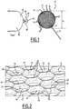
- the figure 1 schematically shows a docking device 10 which externally has the general shape of a sphere 12 having an outside diameter d c .
- the sphere 12 is hollow and comprises an outer surface 14, which is shown in detail on the figure 2 , and an inner surface 16.
- the inner surface 16 of the sphere also has the general shape of a sphere.
- the sphere 12 is provided with a plurality of cells 18 which are regularly distributed around its circumference and which connect its interior with its outside to form together a spherical grid.
- each cell 18 is surrounded by six cells 18 adjacent.
- the opening of each cell 18 is substantially circular, but other forms for opening are possible.
- the sphere 12 On its outer surface 14, the sphere 12 has, between each pair of adjacent cells 18, an edge 20 to which are joined curved side walls 22 of these two adjacent cells.
- the walls 22 are convex towards the outside of the sphere.
- Each cell 18 is thus surrounded by six edges 20 together forming a hexagon with curved sides. In this example, three successive sides of the hexagon are concave towards the center of the hexagon, while the other three sides are convex.
- Each edge 20 is adapted to direct a percussion member against it in one of the adjacent cells by sliding on one of the walls 22.
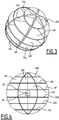
- the Figures 3 and 4 show a structure located inside the mooring device 10.
- the sphere 12 comprises in its interior a plurality of rigid plates 24 a , 24 b , 24 c , 24 d , 24 e , 24 f , 24 g , 24 h , 24 i , at least two of which are respectively orthogonal to each other.
- Each plate 24 has 24 i has a substantially circular shape and a diameter adapted to its position in the sphere 12 so that it is adapted to be connected to the inner surface 16 of the sphere 12.
- At least one of the plates 24 has at 24 i , but not necessarily all the plates, is fixed to the inner surface 16 of the sphere 12 at attachment points 26 located between three adjacent cells 18, so that an attachment device having a clamp comprising two jaws which are respectively inserted into two adjacent cells 18 is not interfered with when its jaws close behind the wall 22 common between these two adjacent cells 18.
- the plates 24 a to 24 i reinforce structurally the sphere 12 against collapse when it is contacted by an autonomous underwater vehicle.
- the plates 24 a to 24 i together form a generally spherical shaped structure having a diameter of at least 70%, in particular at least 80%, of the diameter of the inner surface 16 of the sphere 12.
- Each plate 24a to 24 i has two planar surfaces. These plans together create a resistance to the advancement of the mooring device 10 in the water in all directions.
- the mooring device 10 comprises, in a variant, a buoyancy material 28 for adjusting its buoyancy to the buoyancy of the vessel or submarine to which the mooring device is connected.
- a buoyancy material 28 for adjusting its buoyancy to the buoyancy of the vessel or submarine to which the mooring device is connected.
- the docking device 10 is constructed to have a positive buoyancy.
- the buoyancy material is incorporated into at least one of the plates 24 a to 24 i.
- the mooring device 10 is constructed to have a negative buoyancy, in this case the buoyancy material 28 is replaced by a ballast denser than water, for example lead.
- the docking device 10 is provided inside the sphere 12 with a transponder 30 for a relative positioning system.
- the transponder 30 is arranged in the center of the sphere 12.
- the transponder 30 emits signals, for example acoustic signals, which allow its location.
- the transponder 30 allows a submarine vehicle to find the location of the docking device 10.
- the docking device 10 is connected by a cable 32 to a recovery base arranged on a ship or a submarine.
- the cable 32 is provided with an electrical connection for powering or controlling the transponder 30 or other electrical equipment provided in the sphere 12.
- the cable 32 is connected by a ball system to the mooring device.
- the sphere 12 therefore allows an underwater vehicle to approach it in any direction.
- the sphere 12 forms an omnidirectional hookable target.
- the mooring device has, in another embodiment, another outer shape, for example the shape of a circular or oval spherical sector, for example a half-sphere or three-quarter sphere.
- the outer surface is curved.
- the figure 1 shows a submarine vehicle 40, including an AUV (Autonomous Underwater Vehicle) or a drone.
- AUV Autonomous Underwater Vehicle
- the AUV 40 has an AUV diameter, for example, greater than that of the sphere 12 of the docking device 10.
- the AUV has a nose 42 provided with an attachment device 44 at the tip of the nose 42.
- the hooking device 44 is adapted to hook on the sphere 12 by a simple frontal contact with the sphere, and to remain attached thereafter.
- the attachment device 44 comprises a clamp comprising two movable jaws 46 capable of being closed on themselves.
- the two jaws 46 are locked in their open position shown, and when a trigger device 48, for example a button, arranged between the two jaws is struck, the two jaws 46 are unlocked and close with a spring not shown.
- the two jaws 46 respectively fit into two adjacent cells 18.
- the jaws are first discarded by a camming effect by the walls 22.
- a wall 22 common between these two adjacent cells 18 touches the triggering device 48, and the two jaws 46 close behind each other. said wall 22 common.
- the attachment device 44 is thus passively actuated when the AUV contacts the sphere 12.
- the AUV is then fixed to the sphere 12.
- the docking device 10 When the docking device 10 receives a shock when the AUV clings to it, the docking device 10 has a large inertia due to the planes of the plates 24 a to 24 i . This inertia makes it possible to actuate the trigger device 48 in a secure manner.
- the attachment device 44 comprises an active actuator of the jaws 42, 44 making it possible to hook the AUV 40 to the docking device 10 and to unhook the AUV 40, in a reverse manner to the hooking, by example remotely.
- the attachment device comprises a single pin with a spring-mounted nonreturn device.
- a device 44 ' is shown on the Figures 5 to 7 , which show it at different times entering a cell 18.
- the Figures 5 to 7 show the hooking device 44 'which is adapted to hook on the sphere 12 by a simple frontal contact.
- the hooking device 44 ' comprises a pin 80 which is fixed to the tip of the nose 42 of the AUV 40.
- the pin 80 has, for example, a cylindrical shape, a diameter smaller than the diameter of the cells 18 and a Y axis in the direction of movement of the AUV.
- the pin 80 is provided with a point 82 along the axis Y.
- the pin 80 comprises two movable hooks 84, 86, arranged on opposite sides of the pin 80 and passing through longitudinal slots of this pin.
- Each hook 84, 86 is pivotally mounted about a respective axis of rotation 88, 90.
- the axes of rotation 88, 90 are arranged inside the outer contour of the pin 80 and in front of the hooks 84, 86.
- a portion of the hooks 84, 86 protrude from the pin 80 and has, in section, a substantially triangular shape with a sliding surface 92, 94 extending from its front end beyond the outer contour of the pin 80 and obliquely backward.
- the sliding surfaces 92, 94 are connected to a retaining surface 92, 94 orthogonal to the Y axis of the pin 80.
- the rear ends of the hooks 84, 86 are pushed outwards by springs 96, 98 arranged inside the pin 80.
- the transverse extension of the hooking device 44 'at the rear end of the hooks 84, 86 is greater than the diameter of the cells 18 when the hooks 84, 86 are pushed outwards by the springs 96, 98.
- the hooks 84, 86 thus form a ratchet clasp.
- the tip 82 of the pin slides on a wall 22 to center it in a cell 18 ( figure 5 ).
- the two hooks 84, 86 are pushed by the walls 22 of the cell 18 towards the Y axis of the pin by compressing the springs 96, 98.
- the pin provided with the ratchet clasp comprising the hooks 84, 86 thus prevents backtracking, since the retaining surfaces 92, 94 bear against the inner surface 16 of the sphere 12.
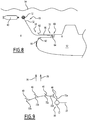
- the figure 8 shows a side view of a recovery base 50 mounted on a submarine 52 dive below the surface of the water 54.
- the submarine 52 has a much larger diameter than the AUV 40.
- the recovery base 50 comprises a housing 56 or dock of longitudinal axis X for accommodating the AUV 40.
- the housing 56 comprises two ends 58, 60 in the direction of movement of the AUV in the housing 56.
- the first end 58 presents a input to allow the AUV 40 to enter and includes convergence plates 62 to guide the docking device 10 and the AUV 40 within the housing 56.
- convergence plates 62 For example, two opposing convergence plates 62 of both sides of the entrance make an angle greater than 10 ° between them.
- a winch 64 is arranged in the recovery base 50 at the second end 60.
- the winch 64 wraps or unrolls the cable 32 which is connected to the sphere 12.
- the winch allows to release the sphere 12 and to pull the sphere 12 in dwelling 56.
- the docking device 10 has a positive buoyancy.
- the sphere 12 is positioned above the submarine 52. This difference in buoyancy with respect to the submarine 52 makes it possible to release the cable 32 from a thruster 66 of the submarine 52 when unwinding or winding the cable 32, and placing the sphere 12 at a different depth of immersion from that of the submarine 52.
- the recovery base 50 can be mounted on a ship or in a hull of the ship and be provided with a docking device 10 having a negative buoyancy.
- the convergence plates 62 help align the AUV on the longitudinal axis X of the recovery base 50 to place the AUV on this axis in the housing 56.
- the diameter of the sphere 12 being smaller than that of the AUV 40, it can be found in the X axis of the housing 56 when the AUV is pulled with the sphere 12 inside the housing 56, whatever the point where the AUV clings to the sphere 12.
- the figure 9 shows in top view the approach of the AUV 40 to the docking device 10 according to the invention, in the presence of a side stream 70.
- the AUV 40 is simplified by a single line.
- the positioning of the AUV 40 at different times has 72, 72 b, 72 c, 72 d and 72 e.
- the current 70 carries it upwards on the figure 9 .
- the AUV is therefore obliged to continuously correct its direction of approach to the sphere 12.
- the docking device 10 comprises a transponder 30
- the AUV 40 receives the transponder signals and always goes to the source of the signals emitted and therefore always towards the sphere 12, following a curve of the dog.
- the AUV 40 clings to the sphere 12 to remain then secured to it.
- the docking device 10 allows an omnidirectional hooking, it guarantees the attachment of the AUV 40 whatever the dynamic disturbances with a basic guidance system of the "dog curve" type.
Landscapes
- Chemical & Material Sciences (AREA)
- Engineering & Computer Science (AREA)
- Combustion & Propulsion (AREA)
- Mechanical Engineering (AREA)
- Ocean & Marine Engineering (AREA)
- Laying Of Electric Cables Or Lines Outside (AREA)
- Electric Cable Installation (AREA)
- Measurement Of Velocity Or Position Using Acoustic Or Ultrasonic Waves (AREA)
Description
- L'invention concerne un dispositif d'amarrage pour un véhicule sous-marin muni d'un dispositif d'accrochage. En outre, la présente invention concerne un système d'amarrage pour un véhicule sous-marin et une base de récupération.
- La demande
US 2011/283929 A1 concerne un dispositif d'amarrage consistant en une masse de béton comprenant une pluralité de tunnels traversant le dispositif. -
US 7 025 014 B1 concerne un dispositif d'amarrage pour un véhicule sous-marin ayant une forme sphérique. - La demande
WO 2008/012472 A1 divulgue une cage immergée connectée par un câble enroulable à une base de récupération. La cage qui comprend un logement et un moyen de réception dans lequel le nez d'un véhicule autonome sous-marin s'engage. Ensuite, le véhicule autonome sous-marin est tiré par le moyen de réception à l'intérieur du logement. Le moyen de réception est propre à pivoter autour de deux axes. - Une telle cage déportée d'un navire permet le découplage des mouvements de la houle par rapport audit véhicule mais constitue une solution complexe.
- De plus, les véhicules autonomes sous-marins n'ont pas de moyen de propulsion latérale pour contrer des effets des perturbations quand ils s'approchent à la cage de manutention. Même si de tels véhicules autonomes sous-marins sont capables d'anticiper des perturbations dynamiques, ce qui est envisageable pour un courant constant, une telle anticipation est beaucoup plus difficile pour des perturbations locales, par exemple liées à une présence d'un sous-marin ayant une taille importante par rapport au véhicule autonome sous-marin, ou à un système de propulsion d'un navire ou d'un sous-marin.
- Le but de la présente invention est de proposer un dispositif très économique d'amarrage pour un véhicule sous-marin qui facilite la récupération du véhicule sous-marin à une base de récupération, par exemple d'un sous-marin.
- Ces buts sont atteints, conformément à l'invention, par un dispositif d'amarrage selon la revendication 1.
- Selon des caractéristiques avantageuses :
- la surface extérieure est bombée ;
- les alvéoles sont adjacentes les unes aux autres ;
- les alvéoles sont séparées par des arêtes d'où partent des parois bombées ;
- la surface extérieure a sensiblement la forme d'un secteur sphérique circulaire ou ovale, notamment d'une demi-sphère, d'un trois-quarts de sphère, ou d'une sphère ;
- le ou les plans de résistance sont agencés à l'intérieur du corps creux ;
- le dispositif d'amarrage comprend au moins trois plans de résistance, dont au moins deux sont sensiblement orthogonaux entre eux ;
- les plans de résistance sont solidaires du corps creux ;
- les plans de résistance sont définis par des plaques reliées par au moins deux points de fixation au corps creux ;
- le dispositif comprend un matériau de flottabilité ou un lest adapté pour ajuster la flottabilité du corps creux ;
- le dispositif d'amarrage comprend un dispositif de signalisation pour signaler au véhicule sous-marin la position du dispositif d'amarrage ;
- le dispositif d'amarrage comprend en outre un câble relié au corps creux ; et/ou
- le câble est relié au corps creux par une liaison rotulante.
- En outre, ces buts sont atteints, conformément à l'invention, par un système d'amarrage pour un véhicule sous-marin, caractérisé en ce qu'il comprend un dispositif d'amarrage suivant l'un quelconque des modes de réalisation ci-dessus, et un dispositif d'accrochage dans au moins une alvéole du corps creux, prévu sur le nez dudit véhicule. Selon des caractéristiques avantageuses :
- le dispositif d'accrochage comprend deux mâchoires d'accrochage dans deux alvéoles du corps creux ; et/ou
- le dispositif d'accrochage comprend un pion d'accrochage dans une alvéole, le pion ayant un diamètre inférieur au diamètre de l'alvéole et étant muni d'un fermoir à cliquet.
- Finalement, ces buts sont atteints, conformément à l'invention, par une base de récupération comprenant un treuil et un dispositif d'amarrage tel que défini ci-dessus, ledit câble étant relié au treuil.
- Selon une caractéristique avantageuse :
- la base de récupération comprend un logement pour le véhicule sous-marin, le treuil étant agencé pour tirer le dispositif d'amarrage dans ledit logement.
- D'autres caractéristiques et avantages de la présente invention ressortiront de la description faite ci-dessous, en référence aux dessins, qui illustrent un exemple de réalisation dépourvu de tout caractère limitatif et dans lequel :
- la
figure 1 est une vue latérale d'un mode de réalisation d'un dispositif d'amarrage selon l'invention, - la
figure 2 est une vue agrandie d'une surface extérieure du dispositif d'amarrage, - la
figure 3 est une vue en perspective d'une structure située à l'intérieur du dispositif d'amarrage, - la
figure 4 est une vue de côté de la structure située à l'intérieur du dispositif d'amarrage, - la
figure 5 est une vue de côté d'un dispositif d'accrochage à pion unique entrant dans une alvéole du dispositif d'amarrage à un premier instant, - la
figure 6 est une vue de côté d'un dispositif d'accrochage à pion unique entrant dans une alvéole du dispositif d'amarrage à un deuxième instant, - la
figure 7 est une vue de côté d'un dispositif d'accrochage à pion unique entrant dans une alvéole du dispositif d'amarrage à un troisième instant, - la
figure 8 est une vue latérale du dispositif d'amarrage accroché à une base de récupération montée sur un sous-marin ; et - la
figure 9 est une vue schématique d'une approche d'un véhicule sous-marin vers le dispositif d'amarrage. - La
figure 1 montre schématiquement un dispositif d'amarrage 10 qui présente extérieurement une forme générale d'une sphère 12 ayant un diamètre extérieur dc. La sphère 12 est creuse et comprend une surface extérieure 14, qui est montrée en détail sur lafigure 2 , et une surface intérieure 16. La surface intérieure 16 de la sphère a également la forme générale d'une sphère. - La sphère 12 est pourvue d'une pluralité d'alvéoles 18 qui sont distribuées régulièrement autour de sa circonférence et qui relient son intérieur avec son extérieur pour former ensemble une grille sphérique. Dans le mode de réalisation représenté, chaque alvéole 18 est entourée de six alvéoles 18 adjacentes. L'ouverture de chaque alvéole 18 est sensiblement circulaire, mais d'autres formes pour l'ouverture sont envisageables. A sa surface extérieure 14, la sphère 12 présente, entre chaque paire d'alvéoles adjacentes 18, une arête 20 à laquelle se joignent des parois latérales incurvées 22 de ces deux alvéoles adjacentes. Les parois 22 sont convexes vers l'extérieur de la sphère. Chaque alvéole 18 est ainsi entourée de six d'arêtes 20 formant ensemble un hexagone à côtés incurvés. Dans cet exemple, trois côtés successifs de l'hexagone sont concaves vers le centre de l'hexagone, tandis que les trois autres côtés sont convexes. Chaque arête 20 est propre à diriger un élément percutant contre celle-ci dans l'une des alvéoles adjacentes en glissant sur l'une des parois 22.
- Les
figures 3 et 4 montrent une structure située à l'intérieur du dispositif d'amarrage 10. La sphère 12 comprend dans son intérieur une pluralité de plaques rigides 24a, 24b, 24c, 24d, 24e, 24f, 24g, 24h, 24i, dont au moins deux sont respectivement orthogonales entre elles. Chaque plaque 24a à 24i a une forme sensiblement circulaire et un diamètre adapté à sa position dans la sphère 12 de façon qu'elle soit propre à être connectée à la surface intérieure 16 de la sphère 12. Au moins une des plaques 24a à 24i, mais pas nécessairement toutes les plaques, est fixée à la surface intérieure 16 de la sphère 12 en des points de fixation 26 situés entre trois alvéoles 18 adjacentes, de manière qu'un dispositif d'accrochage ayant une pince comprenant deux mâchoires qui sont respectivement insérées dans deux alvéoles 18 adjacentes ne soit pas gêné quand ses mâchoires se ferment derrière la paroi 22 commune entre ces deux alvéoles 18 adjacentes. - Dans cet exemple, il est prévu trois plaques méridiennes 22a à 22c, et six plaques parallèles_24d à 24i équidistantes les unes des autres.
- Les plaques 24a à 24i renforcent structurellement la sphère 12 contre un effondrement quand elle est contactée par un véhicule autonome sous-marin.
- Les plaques 24a à 24i forment ensemble une structure de forme générale sphérique ayant un diamètre d'au moins 70%, en particulier au moins 80%, du diamètre de la surface intérieure 16 de la sphère 12.
- Chaque plaque 24a à 24i présente deux surfaces planes. Ces plans créent ensemble une résistance à l'avancement du dispositif d'amarrage 10 dans l'eau dans tous les sens.
- Le dispositif d'amarrage 10 comprend, dans une variante, un matériau de flottabilité 28 pour ajuster sa flottabilité à la flottabilité du navire ou du sous-marin auquel le dispositif d'amarrage est relié. Par exemple, quand le dispositif d'amarrage 10 est relié à un sous-marin submergé, le dispositif d'amarrage 10 est construit pour avoir une flottabilité positive. Dans un exemple de réalisation, le matériau de flottabilité est intégré dans l'une au moins des plaques 24a à 24i. Dans un autre mode de réalisation, le dispositif d'amarrage 10 est construit pour avoir une flottabilité négative, dans ce cas le matériau de flottabilité 28 est remplacé par un lest plus dense que l'eau, par exemple en plomb.
- Finalement, le dispositif d'amarrage 10 est muni à l'intérieur de la sphère 12 d'un transpondeur 30 pour un système de positionnement relatif. Par exemple, le transpondeur 30 est agencé au centre de la sphère 12. Le transpondeur 30 émet des signaux, par exemple des signaux acoustiques, qui permettent sa localisation. Ainsi, le transpondeur 30 permet à un véhicule sous-marin de trouver l'emplacement du dispositif d'amarrage 10.
- Le dispositif d'amarrage 10 est relié par un câble 32 à une base de récupération agencée sur un navire ou un sous-marin. Dans un mode de réalisation, le câble 32 est pourvu d'une connexion électrique pour alimenter ou pour commander le transpondeur 30 ou un autre équipement électrique prévu dans la sphère 12. Dans une variante, le câble 32 est connecté par un système de rotule au dispositif d'amarrage.
- La sphère 12 permet donc à un véhicule sous-marin de s'approcher à celle-ci de n'importe quelle direction. Ainsi, la sphère 12 forme une cible crochetable omnidirectionnelle.
- Le dispositif d'amarrage a, dans un autre mode de réalisation, une autre forme extérieure, par exemple la forme d'un secteur sphérique circulaire ou ovale, par exemple d'une demi-sphère ou d'un trois-quarts de sphère. Dans une variante, la surface extérieure est bombée.
- En outre, la
figure 1 montre un véhicule sous-marin 40, notamment un AUV (Autonomous Underwater Vehicle - véhicule autonome sous-marin) ou un drone. - L'AUV 40 a un diamètre dAUV, par exemple, supérieur à celui de la sphère 12 du dispositif d'amarrage 10. L'AUV a un nez 42 muni d'un dispositif d'accrochage 44 à la pointe du nez 42. Le dispositif d'accrochage 44 est propre à se crocheter sur la sphère 12 par un simple contact frontal avec la sphère, et à en rester solidaire ensuite.
- Dans le mode de réalisation de la
figure 1 , le dispositif d'accrochage 44 comprend une pince comprenant deux mâchoires 46 mobiles propres à être fermées sur elles mêmes. Les deux mâchoires 46 sont bloquées dans leur position ouverte représentée, et lorsqu'un dispositif de déclenchement 48, par exemple un bouton, agencé entre les deux mâchoires est heurté, les deux mâchoires 46 sont débloquées et se ferment à l'aide d'un ressort non représenté. - Quand l'AUV contacte la sphère 12, les deux mâchoires 46 s'insèrent respectivement dans deux alvéoles 18 adjacentes. Dans un mode de réalisation, les mâchoires sont d'abord écartées par un effet de came par les parois 22. Ensuite, une paroi 22 commune entre ces deux alvéoles 18 adjacentes touche le dispositif de déclenchement 48, et les deux mâchoires 46 se ferment derrière ladite paroi 22 commune. Le dispositif d'accrochage 44 est ainsi actionné passivement lors du contact du l'AUV avec la sphère 12. L'AUV est alors fixé à la sphère 12.
- Lorsque le dispositif d'amarrage 10 reçoit un choc quand l'AUV s'accroche à lui, le dispositif d'amarrage 10 présente une inertie importante grâce aux plans des plaques 24a à 24i. Cette inertie permet d'actionner le dispositif de déclenchement 48 de façon sure.
- Dans un autre mode de réalisation, le dispositif d'accrochage 44 comprend un actionneur actif des mâchoires 42, 44 permettant de crocheter l'AUV 40 au dispositif d'amarrage 10 et de décrocheter l'AUV 40, de façon inverse au crochetage, par exemple de façon télécommandée.
- Dans un autre mode de réalisation, le dispositif d'accrochage comprend un pion unique avec un dispositif anti-retour monté sur ressorts. Un tel dispositif 44' est montré sur les
figures 5 à 7 , qui le montrent à différents instants entrant dans une alvéole 18. - Les
figures 5 à 7 montrent le dispositif d'accrochage 44' qui est propre à se crocheter sur la sphère 12 par un simple contact frontal. Le dispositif d'accrochage 44' comprend un pion 80 qui est fixé à la pointe du nez 42 de l'AUV 40. - Le pion 80 a, par exemple, une forme cylindrique, un diamètre inférieur au diamètre des alvéoles 18 et un axe Y suivant la direction de déplacement de l'AUV.
- Le pion 80 est muni d'une pointe 82 suivant l'axe Y. En outre, le pion 80 comporte deux crochets 84, 86 mobiles, agencés sur des côtés opposés du pion 80 et traversant des fentes longitudinales de ce pion. Chaque crochet 84, 86 est monté pivotant autour d'un axe de rotation 88, 90 respectif. Les axes de rotation 88, 90 sont agencés à l'intérieur du contour externe du pion 80 et à l'avant des crochets 84, 86.
- Une partie des crochets 84, 86 fait saillie du pion 80 et a, en section, une forme sensiblement triangulaire avec une surface de glissement 92, 94 s'étendant, à partir de son extrémité avant, au-delà du contour externe du pion 80 et obliquement vers l'arrière. A l'extrémité arrière des crochets 84, 86, les surfaces de glissement 92, 94 sont reliées à une surface de retenue 92, 94 orthogonale à l'axe Y du pion 80.
- Les extrémités arrière des crochets 84, 86 sont poussées vers l'extérieur par des ressorts 96, 98 agencés à l'intérieur du pion 80. L'extension transversale du dispositif d'accrochage 44' à l'extrémité arrière des crochets 84, 86 est supérieure au diamètre des alvéoles 18 quand les crochets 84, 86 sont poussées vers l'extérieur par les ressorts 96, 98. Les crochets 84, 86 forment ainsi un fermoir à cliquet.
- Lorsque l'AUV s'approche de la sphère 12, la pointe 82 du pion glisse sur une paroi 22 pour le centrer dans une alvéole 18 (
figure 5 ). Dans l'étape suivante, montrée sur lafigure 6 , les deux crochets 84, 86 sont poussés par les parois 22 de l'alvéole 18 vers l'axe Y du pion en comprimant les ressorts 96, 98. - Quand le pion est complètement inséré dans l'alvéole 18 et les surfaces de retenue ont dépassé la surface intérieure 16 de la sphère 12, les ressorts 96, 98 repoussent les crochets 84, 86 vers l'extérieur (
figure 7 ). - Le pion muni du fermoir à cliquet comprenant les crochets 84, 86 empêche donc de revenir en arrière, car les surfaces de retenue 92, 94 viennent en appui contre la surface intérieure 16 de la sphère 12.
- La
figure 8 montre une vue latérale d'une base de récupération 50 montée sur un sous-marin 52 en plongée sous la surface de l'eau 54. Le sous-marin 52 a un diamètre beaucoup plus important que l'AUV 40. - La base de récupération 50 comprend un logement 56 ou dock d'axe longitudinal X pour y loger l'AUV 40. Le logement 56 comprend deux extrémités 58, 60 dans le sens de déplacement de l'AUV dans le logement 56. La première extrémité 58 présente une entrée pour permettre à l'AUV 40 d'y entrer et comprend des plaques de convergence 62 pour guider le dispositif d'amarrage 10 et l'AUV 40 à l'intérieur du logement 56. Par exemple, deux plaques de convergence 62 opposées de part et d'autre de l'entrée font entre elles un angle supérieur à 10°.
- Un treuil 64 est agencé dans la base de récupération 50 à la deuxième extrémité 60. Le treuil 64 enroule ou déroule le câble 32 qui est relié à la sphère 12. Ainsi, le treuil permet de lâcher la sphère 12 et de tirer la sphère 12 dans le logement 56.
- Comme il est décrit ci-dessus, le dispositif d'amarrage 10 a une flottabilité positive. Lorsque le câble 32 est déroulé, la sphère 12 se positionne donc au-dessus du sous-marin 52. Cette différence de flottabilité par rapport au sous-marin 52 permet de dégager le câble 32 d'un propulseur 66 du sous-marin 52 lors du déroulage ou de l'enroulage du câble 32, et de placer la sphère 12 à une profondeur d'immersion différente de celle du sous-marin 52.
- De même, la base de récupération 50 peut être montée sur un navire ou dans une carène du navire et être munie d'un dispositif d'amarrage 10 ayant une flottabilité négative.
- Lorsque l'AUV est accroché à la sphère 12 et est tiré avec elle à l'intérieur du logement 56, les plaques de convergence 62 aident à aligner l'AUV sur l'axe longitudinal X de la base de récupération 50 pour placer l'AUV sur cet axe dans le logement 56. De plus, le diamètre de la sphère 12 étant inférieur à celui de l'AUV 40, celui-ci peut se retrouver dans l'axe X du logement 56 lorsque l'AUV est tiré avec la sphère 12 à l'intérieur du logement 56, quelque soit le point où l'AUV s'accroche à la sphère 12.
- La
figure 9 montre en vue de dessus l'approche de l'AUV 40 vers le dispositif d'amarrage 10 selon l'invention, en présence d'un courant latéral 70. L'AUV 40 est simplifié par un simple trait. On voit sur lafigure 9 le positionnement de l'AUV 40 à différents instants 72a, 72b, 72c, 72d et 72e. Lors de l'approche du l'AUV 40 de la sphère 12, le courant 70 l'emporte vers le haut sur lafigure 9 . L'AUV est donc obligé de corriger en continu sa direction d'approche de la sphère 12. Comme le dispositif d'amarrage 10 comprend un transpondeur 30, l'AUV 40 reçoit les signaux du transpondeur et se dirige toujours vers la source des signaux émis et donc toujours vers la sphère 12, suivant une courbe du chien. - A l'instant 72e, l'AUV 40 s'accroche à la sphère 12 pour rester ensuite solidaire de celle-ci. Comme le dispositif d'amarrage 10 permet un accrochage omnidirectionnel, il garantit l'accrochage de l'AUV 40 quelles que soient les perturbations dynamiques avec un système de guidage basique du type « courbe du chien ».
Claims (14)
- Dispositif d'amarrage (10) pour un véhicule sous-marin (40) muni d'un dispositif d'accrochage (44), le dispositif d'amarrage comprenant un corps (12) creux alvéolé propre à coopérer avec le dispositif d'accrochage (44) du véhicule sous-marin, le corps creux (12) étant pourvu d'une surface extérieure (14) alvéolée qui est dirigée vers une pluralité de directions, caractérisé en ce qu'il comprend au moins un plan de résistance (24a, 24b, 24c, 24d, 24e, 24f, 24g, 24h, 24i) propre à créer une inertie lors d'un choc du véhicule sous-marin en provenance de chacune de la pluralité de directions ou d'une direction voisine de celles-ci, le ou les plans de résistance (24a, 24b, 24c, 24d, 24e, 24f, 24g, 24h, 24i) étant agencés à l'intérieur du corps creux (12).
- Dispositif selon la revendication 1, caractérisé en ce que la surface extérieure (14) est bombée.
- Dispositif selon la revendication 1 ou 2, caractérisé en ce que les alvéoles (18) sont adjacentes les unes aux autres.
- Dispositif selon l'une des revendications précédentes, caractérisé en ce que les alvéoles (18) sont séparées par des arêtes (20) d'où partent des parois bombées (22).
- Dispositif selon l'une des revendications précédentes, caractérisé en ce que la surface extérieure a sensiblement la forme d'un secteur sphérique circulaire ou ovale, notamment d'une demi-sphère, d'un trois-quarts de sphère, ou d'une sphère (12).
- Dispositif selon l'une des revendications précédentes, caractérisé par au moins trois plans de résistance, dont au moins deux sont sensiblement orthogonaux entre eux.
- Dispositif selon l'une des revendications précédentes, caractérisé en ce que les plans de résistance sont solidaires du corps creux (12) et/ou les plans de résistance sont définis par des plaques (24a, 24b, 24c, 24d, 24e, 24f, 24g, 24h, 24i) reliées par au moins deux points de fixation au corps creux (12).
- Dispositif selon l'une des revendications précédentes, caractérisé en ce qu'il comprend un matériau de flottabilité (28) ou un lest adapté pour ajuster la flottabilité du corps creux (12).
- Dispositif selon l'une des revendications précédentes, caractérisé en ce qu'il comprend un dispositif de signalisation (30) pour signaler au véhicule sous-marin (40) la position du dispositif d'amarrage (10).
- Dispositif selon l'une des revendications précédentes, caractérisé en ce qu'il comprend en outre un câble (32) relié au corps creux (12), et, en particulier, le câble (32) étant relié au corps creux (12) par une liaison rotulante (34).
- Système d'amarrage pour un véhicule sous-marin (40), caractérisé en ce qu'il comprend :- un dispositif d'amarrage (10) suivant l'une quelconque des revendications précédentes, et- un dispositif d'accrochage (44, 44') dans au moins une alvéole (18) du corps creux (12), prévues sur le nez dudit véhicule (40).
- Système d'amarrage selon la revendication 11, caractérisé en ce que le dispositif d'accrochage comprend deux mâchoires (46) d'accrochage dans deux alvéoles (18) du corps creux (12), ou le dispositif d'accrochage comprend un pion (80) d'accrochage dans une alvéole (18), le pion ayant un diamètre inférieur au diamètre de l'alvéole et étant muni d'un fermoir à cliquet (84, 86, 96, 98).
- Base de récupération (50) comprenant un treuil (64) et un dispositif d'amarrage (10) selon la revendication 10, ledit câble (32) étant relié au treuil (64).
- Base de récupération selon la revendication 13, caractérisée en ce qu'elle comprend un logement (56) pour le véhicule sous-marin, le treuil étant agencé pour tirer le dispositif d'amarrage (10, 12) dans ledit logement.
Applications Claiming Priority (2)
| Application Number | Priority Date | Filing Date | Title |
|---|---|---|---|
| FR1253367A FR2989352B1 (fr) | 2012-04-12 | 2012-04-12 | Dispositif d'amarrage pour un vehicule sous-marin, systeme d'amarrage et base de recuperation |
| PCT/EP2013/057028 WO2013152974A1 (fr) | 2012-04-12 | 2013-04-03 | Dispositif d'amarrage pour un vehicule sous-marin, systeme d'amarrage et base de recuperation |
Publications (2)
| Publication Number | Publication Date |
|---|---|
| EP2836422A1 EP2836422A1 (fr) | 2015-02-18 |
| EP2836422B1 true EP2836422B1 (fr) | 2019-12-11 |
Family
ID=46852105
Family Applications (1)
| Application Number | Title | Priority Date | Filing Date |
|---|---|---|---|
| EP13713901.0A Active EP2836422B1 (fr) | 2012-04-12 | 2013-04-03 | Dispositif d'amarrage pour un vehicule sous-marin, systeme d'amarrage et base de recuperation |
Country Status (5)
| Country | Link |
|---|---|
| EP (1) | EP2836422B1 (fr) |
| KR (1) | KR102167606B1 (fr) |
| ES (1) | ES2765180T3 (fr) |
| FR (1) | FR2989352B1 (fr) |
| WO (1) | WO2013152974A1 (fr) |
Families Citing this family (2)
| Publication number | Priority date | Publication date | Assignee | Title |
|---|---|---|---|---|
| US9914513B2 (en) * | 2014-11-07 | 2018-03-13 | Abb Schweiz Ag | Transformer in-situ inspection vehicle with a cage hull |
| NO345094B1 (en) | 2018-09-21 | 2020-09-28 | Usea As | A marine structure comprising a launch and recovery system |
Citations (1)
| Publication number | Priority date | Publication date | Assignee | Title |
|---|---|---|---|---|
| US7025014B1 (en) * | 2004-03-03 | 2006-04-11 | The United States Of America As Represented By The Secretary Of The Navy | Sea vessel retrieval of unmanned underwater vehicles |
Family Cites Families (2)
| Publication number | Priority date | Publication date | Assignee | Title |
|---|---|---|---|---|
| FR2904287B1 (fr) | 2006-07-26 | 2008-10-24 | Ifremer | Appareil de recuperation d'un engin sous-marin ou marin |
| US8869746B2 (en) * | 2009-08-06 | 2014-10-28 | Stewart Hardison | Mooring structure with habitat features for marine animals |
-
2012
- 2012-04-12 FR FR1253367A patent/FR2989352B1/fr not_active Expired - Fee Related
-
2013
- 2013-04-03 KR KR1020147030772A patent/KR102167606B1/ko not_active Expired - Fee Related
- 2013-04-03 ES ES13713901T patent/ES2765180T3/es active Active
- 2013-04-03 WO PCT/EP2013/057028 patent/WO2013152974A1/fr not_active Ceased
- 2013-04-03 EP EP13713901.0A patent/EP2836422B1/fr active Active
Patent Citations (1)
| Publication number | Priority date | Publication date | Assignee | Title |
|---|---|---|---|---|
| US7025014B1 (en) * | 2004-03-03 | 2006-04-11 | The United States Of America As Represented By The Secretary Of The Navy | Sea vessel retrieval of unmanned underwater vehicles |
Also Published As
| Publication number | Publication date |
|---|---|
| KR102167606B1 (ko) | 2020-10-19 |
| EP2836422A1 (fr) | 2015-02-18 |
| KR20140143822A (ko) | 2014-12-17 |
| WO2013152974A1 (fr) | 2013-10-17 |
| ES2765180T3 (es) | 2020-06-08 |
| FR2989352A1 (fr) | 2013-10-18 |
| FR2989352B1 (fr) | 2014-05-09 |
Similar Documents
| Publication | Publication Date | Title |
|---|---|---|
| EP2152570B1 (fr) | Appareil submersible a membranes souples d'etancheite | |
| WO2014135522A1 (fr) | Systeme et procede de recuperation d'un engin sous-marin autonome | |
| EP3027498B1 (fr) | Dispositif de remorquage a chaumard en deux parties | |
| CA2784188C (fr) | Engin marin ou sous-marin et procede d'arrimage associe | |
| CA1166153A (fr) | Dispositif de connexion deconnectable pour ligne guide | |
| FR2972423A1 (fr) | Procede et systeme de lancement d'un satellite | |
| FR3040682A1 (fr) | Dispositif d'amarrage d'un navire a un poste d'amarrage d'un ponton et ponton correspondant | |
| FR3127468A1 (fr) | Un propulseur sous-marin multifonctionnel | |
| CA2960706C (fr) | Engin marin ou sous-marin et procede d'arrimage associe | |
| EP2836422A1 (fr) | Dispositif d'amarrage pour un vehicule sous-marin, systeme d'amarrage et base de recuperation | |
| FR3024973A1 (fr) | Dispositif d'accueil d'un engin sous-marin et vehicule naval associe | |
| FR3094349A1 (fr) | Station de recharge pour drone | |
| JP5600848B2 (ja) | 特に流線形のスケールを備える、流線形牽引ロープ用のスケール回転装置 | |
| FR2771997A1 (fr) | Perfectionnements apportes aux barres de navigation | |
| EP3245123B1 (fr) | Dispositif de protection des objets sous-marins remorques contre les lignes de peche | |
| EP4060124B1 (fr) | Ensemble de couplage securise d'un outil sur un bras de travail d'un engin de travaux publics a fonctionnement ameliore | |
| EP4051569B1 (fr) | Taquet pour amarrage d'une embarcation et ensemble d'amarrage à taquet et cordage à butoir | |
| EP1852345A1 (fr) | Sytème de manoeuvre d'une ancre | |
| JP2012130281A (ja) | バット及びフィッシングロッド | |
| FR3021289A1 (fr) | Dispositif de recuperation d'un engin mobile, notamment d'un drone sous-marin | |
| EP2792593B1 (fr) | Ensemble perfectionné d'un mât télescopique et d'un dispositif de support d'un équipement, pour un véhicule sous-marin | |
| FR2950859A1 (fr) | Lest de quille mobile coulissant sur un voile de quille pivotant | |
| FR2828991A1 (fr) | Cage pour animaux a longueur utile reduite | |
| FR3065437A1 (fr) | Systeme de prise de parc de conditionnement d'air pour la connexion d'un generateur d'air a un aeronef | |
| FR3103008A1 (fr) | Procédé de déblocage d’une poignée d’ouvrant en conditions de blocage en position escamotée. |
Legal Events
| Date | Code | Title | Description |
|---|---|---|---|
| PUAI | Public reference made under article 153(3) epc to a published international application that has entered the european phase |
Free format text: ORIGINAL CODE: 0009012 |
|
| 17P | Request for examination filed |
Effective date: 20141105 |
|
| AK | Designated contracting states |
Kind code of ref document: A1 Designated state(s): AL AT BE BG CH CY CZ DE DK EE ES FI FR GB GR HR HU IE IS IT LI LT LU LV MC MK MT NL NO PL PT RO RS SE SI SK SM TR |
|
| AX | Request for extension of the european patent |
Extension state: BA ME |
|
| DAX | Request for extension of the european patent (deleted) | ||
| RAP1 | Party data changed (applicant data changed or rights of an application transferred) |
Owner name: NAVAL GROUP |
|
| RIC1 | Information provided on ipc code assigned before grant |
Ipc: B63B 21/66 20060101ALI20180713BHEP Ipc: B63B 21/00 20060101ALI20180713BHEP Ipc: B63G 8/00 20060101AFI20180713BHEP |
|
| STAA | Information on the status of an ep patent application or granted ep patent |
Free format text: STATUS: EXAMINATION IS IN PROGRESS |
|
| 17Q | First examination report despatched |
Effective date: 20180913 |
|
| GRAP | Despatch of communication of intention to grant a patent |
Free format text: ORIGINAL CODE: EPIDOSNIGR1 |
|
| STAA | Information on the status of an ep patent application or granted ep patent |
Free format text: STATUS: GRANT OF PATENT IS INTENDED |
|
| RIC1 | Information provided on ipc code assigned before grant |
Ipc: B63G 8/42 20060101ALN20190527BHEP Ipc: B63G 8/00 20060101AFI20190527BHEP Ipc: B63B 21/00 20060101ALI20190527BHEP Ipc: B63B 21/66 20060101ALI20190527BHEP |
|
| INTG | Intention to grant announced |
Effective date: 20190621 |
|
| RIC1 | Information provided on ipc code assigned before grant |
Ipc: B63G 8/00 20060101AFI20190607BHEP Ipc: B63B 21/66 20060101ALI20190607BHEP Ipc: B63G 8/42 20060101ALN20190607BHEP Ipc: B63B 21/00 20060101ALI20190607BHEP |
|
| GRAS | Grant fee paid |
Free format text: ORIGINAL CODE: EPIDOSNIGR3 |
|
| GRAJ | Information related to disapproval of communication of intention to grant by the applicant or resumption of examination proceedings by the epo deleted |
Free format text: ORIGINAL CODE: EPIDOSDIGR1 |
|
| GRAL | Information related to payment of fee for publishing/printing deleted |
Free format text: ORIGINAL CODE: EPIDOSDIGR3 |
|
| REG | Reference to a national code |
Ref country code: DE Ref legal event code: R079 Ref document number: 602013063858 Country of ref document: DE Free format text: PREVIOUS MAIN CLASS: B63B0021660000 Ipc: B63G0008000000 |
|
| STAA | Information on the status of an ep patent application or granted ep patent |
Free format text: STATUS: EXAMINATION IS IN PROGRESS |
|
| GRAR | Information related to intention to grant a patent recorded |
Free format text: ORIGINAL CODE: EPIDOSNIGR71 |
|
| STAA | Information on the status of an ep patent application or granted ep patent |
Free format text: STATUS: GRANT OF PATENT IS INTENDED |
|
| GRAA | (expected) grant |
Free format text: ORIGINAL CODE: 0009210 |
|
| STAA | Information on the status of an ep patent application or granted ep patent |
Free format text: STATUS: THE PATENT HAS BEEN GRANTED |
|
| INTC | Intention to grant announced (deleted) | ||
| RIC1 | Information provided on ipc code assigned before grant |
Ipc: B63B 21/66 20060101ALI20191022BHEP Ipc: B63B 21/00 20060101ALI20191022BHEP Ipc: B63G 8/00 20060101AFI20191022BHEP Ipc: B63G 8/42 20060101ALN20191022BHEP |
|
| INTG | Intention to grant announced |
Effective date: 20191030 |
|
| AK | Designated contracting states |
Kind code of ref document: B1 Designated state(s): AL AT BE BG CH CY CZ DE DK EE ES FI FR GB GR HR HU IE IS IT LI LT LU LV MC MK MT NL NO PL PT RO RS SE SI SK SM TR |
|
| REG | Reference to a national code |
Ref country code: GB Ref legal event code: FG4D Free format text: NOT ENGLISH |
|
| REG | Reference to a national code |
Ref country code: CH Ref legal event code: EP |
|
| REG | Reference to a national code |
Ref country code: AT Ref legal event code: REF Ref document number: 1211938 Country of ref document: AT Kind code of ref document: T Effective date: 20191215 |
|
| REG | Reference to a national code |
Ref country code: DE Ref legal event code: R096 Ref document number: 602013063858 Country of ref document: DE |
|
| REG | Reference to a national code |
Ref country code: IE Ref legal event code: FG4D Free format text: LANGUAGE OF EP DOCUMENT: FRENCH |
|
| REG | Reference to a national code |
Ref country code: NO Ref legal event code: T2 Effective date: 20191211 |
|
| REG | Reference to a national code |
Ref country code: NL Ref legal event code: FP |
|
| REG | Reference to a national code |
Ref country code: SE Ref legal event code: TRGR |
|
| REG | Reference to a national code |
Ref country code: LT Ref legal event code: MG4D |
|
| PG25 | Lapsed in a contracting state [announced via postgrant information from national office to epo] |
Ref country code: FI Free format text: LAPSE BECAUSE OF FAILURE TO SUBMIT A TRANSLATION OF THE DESCRIPTION OR TO PAY THE FEE WITHIN THE PRESCRIBED TIME-LIMIT Effective date: 20191211 Ref country code: LT Free format text: LAPSE BECAUSE OF FAILURE TO SUBMIT A TRANSLATION OF THE DESCRIPTION OR TO PAY THE FEE WITHIN THE PRESCRIBED TIME-LIMIT Effective date: 20191211 Ref country code: LV Free format text: LAPSE BECAUSE OF FAILURE TO SUBMIT A TRANSLATION OF THE DESCRIPTION OR TO PAY THE FEE WITHIN THE PRESCRIBED TIME-LIMIT Effective date: 20191211 Ref country code: BG Free format text: LAPSE BECAUSE OF FAILURE TO SUBMIT A TRANSLATION OF THE DESCRIPTION OR TO PAY THE FEE WITHIN THE PRESCRIBED TIME-LIMIT Effective date: 20200311 |
|
| REG | Reference to a national code |
Ref country code: GR Ref legal event code: EP Ref document number: 20200400251 Country of ref document: GR Effective date: 20200511 |
|
| PG25 | Lapsed in a contracting state [announced via postgrant information from national office to epo] |
Ref country code: HR Free format text: LAPSE BECAUSE OF FAILURE TO SUBMIT A TRANSLATION OF THE DESCRIPTION OR TO PAY THE FEE WITHIN THE PRESCRIBED TIME-LIMIT Effective date: 20191211 Ref country code: RS Free format text: LAPSE BECAUSE OF FAILURE TO SUBMIT A TRANSLATION OF THE DESCRIPTION OR TO PAY THE FEE WITHIN THE PRESCRIBED TIME-LIMIT Effective date: 20191211 |
|
| REG | Reference to a national code |
Ref country code: ES Ref legal event code: FG2A Ref document number: 2765180 Country of ref document: ES Kind code of ref document: T3 Effective date: 20200608 |
|
| PG25 | Lapsed in a contracting state [announced via postgrant information from national office to epo] |
Ref country code: AL Free format text: LAPSE BECAUSE OF FAILURE TO SUBMIT A TRANSLATION OF THE DESCRIPTION OR TO PAY THE FEE WITHIN THE PRESCRIBED TIME-LIMIT Effective date: 20191211 |
|
| PG25 | Lapsed in a contracting state [announced via postgrant information from national office to epo] |
Ref country code: EE Free format text: LAPSE BECAUSE OF FAILURE TO SUBMIT A TRANSLATION OF THE DESCRIPTION OR TO PAY THE FEE WITHIN THE PRESCRIBED TIME-LIMIT Effective date: 20191211 Ref country code: PT Free format text: LAPSE BECAUSE OF FAILURE TO SUBMIT A TRANSLATION OF THE DESCRIPTION OR TO PAY THE FEE WITHIN THE PRESCRIBED TIME-LIMIT Effective date: 20200506 Ref country code: RO Free format text: LAPSE BECAUSE OF FAILURE TO SUBMIT A TRANSLATION OF THE DESCRIPTION OR TO PAY THE FEE WITHIN THE PRESCRIBED TIME-LIMIT Effective date: 20191211 Ref country code: CZ Free format text: LAPSE BECAUSE OF FAILURE TO SUBMIT A TRANSLATION OF THE DESCRIPTION OR TO PAY THE FEE WITHIN THE PRESCRIBED TIME-LIMIT Effective date: 20191211 |
|
| PG25 | Lapsed in a contracting state [announced via postgrant information from national office to epo] |
Ref country code: IS Free format text: LAPSE BECAUSE OF FAILURE TO SUBMIT A TRANSLATION OF THE DESCRIPTION OR TO PAY THE FEE WITHIN THE PRESCRIBED TIME-LIMIT Effective date: 20200411 Ref country code: SK Free format text: LAPSE BECAUSE OF FAILURE TO SUBMIT A TRANSLATION OF THE DESCRIPTION OR TO PAY THE FEE WITHIN THE PRESCRIBED TIME-LIMIT Effective date: 20191211 Ref country code: SM Free format text: LAPSE BECAUSE OF FAILURE TO SUBMIT A TRANSLATION OF THE DESCRIPTION OR TO PAY THE FEE WITHIN THE PRESCRIBED TIME-LIMIT Effective date: 20191211 |
|
| REG | Reference to a national code |
Ref country code: DE Ref legal event code: R097 Ref document number: 602013063858 Country of ref document: DE |
|
| REG | Reference to a national code |
Ref country code: AT Ref legal event code: MK05 Ref document number: 1211938 Country of ref document: AT Kind code of ref document: T Effective date: 20191211 |
|
| PLBE | No opposition filed within time limit |
Free format text: ORIGINAL CODE: 0009261 |
|
| STAA | Information on the status of an ep patent application or granted ep patent |
Free format text: STATUS: NO OPPOSITION FILED WITHIN TIME LIMIT |
|
| PG25 | Lapsed in a contracting state [announced via postgrant information from national office to epo] |
Ref country code: DK Free format text: LAPSE BECAUSE OF FAILURE TO SUBMIT A TRANSLATION OF THE DESCRIPTION OR TO PAY THE FEE WITHIN THE PRESCRIBED TIME-LIMIT Effective date: 20191211 |
|
| 26N | No opposition filed |
Effective date: 20200914 |
|
| PG25 | Lapsed in a contracting state [announced via postgrant information from national office to epo] |
Ref country code: SI Free format text: LAPSE BECAUSE OF FAILURE TO SUBMIT A TRANSLATION OF THE DESCRIPTION OR TO PAY THE FEE WITHIN THE PRESCRIBED TIME-LIMIT Effective date: 20191211 Ref country code: AT Free format text: LAPSE BECAUSE OF FAILURE TO SUBMIT A TRANSLATION OF THE DESCRIPTION OR TO PAY THE FEE WITHIN THE PRESCRIBED TIME-LIMIT Effective date: 20191211 Ref country code: PL Free format text: LAPSE BECAUSE OF FAILURE TO SUBMIT A TRANSLATION OF THE DESCRIPTION OR TO PAY THE FEE WITHIN THE PRESCRIBED TIME-LIMIT Effective date: 20191211 Ref country code: MC Free format text: LAPSE BECAUSE OF FAILURE TO SUBMIT A TRANSLATION OF THE DESCRIPTION OR TO PAY THE FEE WITHIN THE PRESCRIBED TIME-LIMIT Effective date: 20191211 |
|
| REG | Reference to a national code |
Ref country code: CH Ref legal event code: PL |
|
| PG25 | Lapsed in a contracting state [announced via postgrant information from national office to epo] |
Ref country code: LI Free format text: LAPSE BECAUSE OF NON-PAYMENT OF DUE FEES Effective date: 20200430 Ref country code: LU Free format text: LAPSE BECAUSE OF NON-PAYMENT OF DUE FEES Effective date: 20200403 Ref country code: CH Free format text: LAPSE BECAUSE OF NON-PAYMENT OF DUE FEES Effective date: 20200430 |
|
| PG25 | Lapsed in a contracting state [announced via postgrant information from national office to epo] |
Ref country code: IE Free format text: LAPSE BECAUSE OF NON-PAYMENT OF DUE FEES Effective date: 20200403 |
|
| PG25 | Lapsed in a contracting state [announced via postgrant information from national office to epo] |
Ref country code: MT Free format text: LAPSE BECAUSE OF FAILURE TO SUBMIT A TRANSLATION OF THE DESCRIPTION OR TO PAY THE FEE WITHIN THE PRESCRIBED TIME-LIMIT Effective date: 20191211 Ref country code: CY Free format text: LAPSE BECAUSE OF FAILURE TO SUBMIT A TRANSLATION OF THE DESCRIPTION OR TO PAY THE FEE WITHIN THE PRESCRIBED TIME-LIMIT Effective date: 20191211 |
|
| PGFP | Annual fee paid to national office [announced via postgrant information from national office to epo] |
Ref country code: NO Payment date: 20220328 Year of fee payment: 10 |
|
| PG25 | Lapsed in a contracting state [announced via postgrant information from national office to epo] |
Ref country code: MK Free format text: LAPSE BECAUSE OF FAILURE TO SUBMIT A TRANSLATION OF THE DESCRIPTION OR TO PAY THE FEE WITHIN THE PRESCRIBED TIME-LIMIT Effective date: 20191211 |
|
| PG25 | Lapsed in a contracting state [announced via postgrant information from national office to epo] |
Ref country code: IT Free format text: LAPSE BECAUSE OF NON-PAYMENT OF DUE FEES Effective date: 20220403 |
|
| REG | Reference to a national code |
Ref country code: NO Ref legal event code: MMEP |
|
| PG25 | Lapsed in a contracting state [announced via postgrant information from national office to epo] |
Ref country code: NO Free format text: LAPSE BECAUSE OF NON-PAYMENT OF DUE FEES Effective date: 20230430 |
|
| PGFP | Annual fee paid to national office [announced via postgrant information from national office to epo] |
Ref country code: DE Payment date: 20250411 Year of fee payment: 13 |
|
| PGFP | Annual fee paid to national office [announced via postgrant information from national office to epo] |
Ref country code: GB Payment date: 20250417 Year of fee payment: 13 Ref country code: ES Payment date: 20250512 Year of fee payment: 13 |
|
| PGFP | Annual fee paid to national office [announced via postgrant information from national office to epo] |
Ref country code: IT Payment date: 20250409 Year of fee payment: 13 Ref country code: BE Payment date: 20250423 Year of fee payment: 13 |
|
| PGFP | Annual fee paid to national office [announced via postgrant information from national office to epo] |
Ref country code: SE Payment date: 20250422 Year of fee payment: 13 |
|
| PG25 | Lapsed in a contracting state [announced via postgrant information from national office to epo] |
Ref country code: IT Free format text: LAPSE BECAUSE OF NON-PAYMENT OF DUE FEES Effective date: 20220403 |
|
| PGRI | Patent reinstated in contracting state [announced from national office to epo] |
Ref country code: IT Effective date: 20230707 |
|
| PGFP | Annual fee paid to national office [announced via postgrant information from national office to epo] |
Ref country code: NL Payment date: 20260326 Year of fee payment: 14 |
|
| PGFP | Annual fee paid to national office [announced via postgrant information from national office to epo] |
Ref country code: FR Payment date: 20260310 Year of fee payment: 14 |
|
| PGFP | Annual fee paid to national office [announced via postgrant information from national office to epo] |
Ref country code: TR Payment date: 20260325 Year of fee payment: 14 |
|
| PGFP | Annual fee paid to national office [announced via postgrant information from national office to epo] |
Ref country code: GR Payment date: 20260320 Year of fee payment: 14 |