EP2835581A2 - Abdeckeinrichtung zum Abdecken einer radialen Öffnung in einer Gaszufuhrleitung für einen Gasbrenner, Gaszufuhreinrichtung für einen Gasbrenner und Kochstelle - Google Patents
Abdeckeinrichtung zum Abdecken einer radialen Öffnung in einer Gaszufuhrleitung für einen Gasbrenner, Gaszufuhreinrichtung für einen Gasbrenner und Kochstelle Download PDFInfo
- Publication number
- EP2835581A2 EP2835581A2 EP14178299.5A EP14178299A EP2835581A2 EP 2835581 A2 EP2835581 A2 EP 2835581A2 EP 14178299 A EP14178299 A EP 14178299A EP 2835581 A2 EP2835581 A2 EP 2835581A2
- Authority
- EP
- European Patent Office
- Prior art keywords
- gas supply
- supply line
- gas
- covering
- covering device
- Prior art date
- Legal status (The legal status is an assumption and is not a legal conclusion. Google has not performed a legal analysis and makes no representation as to the accuracy of the status listed.)
- Granted
Links
Images


Classifications
-
- F—MECHANICAL ENGINEERING; LIGHTING; HEATING; WEAPONS; BLASTING
- F23—COMBUSTION APPARATUS; COMBUSTION PROCESSES
- F23D—BURNERS
- F23D14/00—Burners for combustion of a gas, e.g. of a gas stored under pressure as a liquid
- F23D14/46—Details
- F23D14/62—Mixing devices; Mixing tubes
- F23D14/64—Mixing devices; Mixing tubes with injectors
-
- F—MECHANICAL ENGINEERING; LIGHTING; HEATING; WEAPONS; BLASTING
- F23—COMBUSTION APPARATUS; COMBUSTION PROCESSES
- F23D—BURNERS
- F23D2900/00—Special features of, or arrangements for burners using fluid fuels or solid fuels suspended in a carrier gas
- F23D2900/14—Special features of gas burners
- F23D2900/14062—Special features of gas burners for cooking ranges having multiple flame rings
Definitions
- the present invention relates to a cover device for covering a radial opening in a gas supply pipe for a gas burner, a gas supply device for a gas burner and a cooking point.
- a radial opening may be provided on the gas supply line.
- a gas supply line For this purpose, a radial opening may be provided on the gas supply line.
- the gas burner is used for different types of gas, a cross-sectional area of the radial opening is adjustable.
- the radial opening can be opened according to the required amount of primary air, partially covered or completely closed. This can be achieved, for example, by slotted cylindrical sleeves which are spring-biased and which are applied to the gas supply line to partially or completely close the radial opening.
- an object of the present invention is to provide an improved and easy-to-handle cover device for covering an opening in a gas supply line.
- a covering device for covering a radial opening in a gas supply pipe for a gas burner with a gripping portion which is adapted to at least partially positively surround the gas supply line and cover the radial opening, and arranged on the gripping portion handling portion for handling the cover with a radial sliding of the cover on the gas supply line.
- the covering device is designed to change a cross-sectional area of the radial opening of the gas supply line, in particular to reduce it.
- the cover device can easily and radially without tools the gas supply line be postponed.
- the gripping portion is spring biased so that it is bent when pushed onto the gas supply line and thus at least partially positively engages around.
- an inner diameter of the Umgreifabitess is smaller than an outer diameter of the gas supply line. In this way, a spring bias of the Umgreifabitess be achieved.
- the cover can be quickly and easily installed, disassembled or replaced in a built-in gas hob gas burner. As a result, a high flexibility in the fuel used can be achieved.
- the gas supply line and the Umgreifabites are designed such that the Umgreifabites exerts a radial holding force in the direction of the gas supply line.
- a sealing means may be provided between the Umgreifabites and the supply line. All elements of the embodiments of the covering device explained below are merely optional.
- the covering device has an anti-rotation element, which is configured to prevent a twisting of the covering device relative to the gas supply line.
- the covering device has two anti-rotation elements.
- the anti-rotation elements can intervene in a form-fitting manner, for example, in bores, ribs, protrusions or the like provided on an outer side of the gas supply line.
- the anti-rotation element ensures a well-defined positioning of the covering device on the gas supply line.
- the anti-rotation element allows easy installation of the cover, since it is automatically positioned by means of the anti-rotation element to the gas supply line.
- the anti-rotation element is adapted to engage in the radial opening of the gas supply line to prevent twisting of the cover relative to the gas supply line.
- the cover device has two anti-rotation elements, which engage in opposite radial openings of the gas supply line.
- the anti-rotation element engages positively in the radial opening.
- the anti-rotation ensures a better seal the radial opening.
- the anti-rotation element extends out of the gripping portion in the direction of the gas supply line.
- the Umgreifabites has, for example, a cylindrical shape with a circumferential wall portion from which extends the anti-rotation element out.
- the anti-rotation element preferably extends toward a central axis of the cylindrical gripping portion.
- the anti-rotation element may for example be formed as a fold of Umgreifabitess.
- the anti-rotation element is in particular centrein Publishedig formed with the Umgreifabites. The fact that the anti-rotation element is preferably formed as a fold of Umgreifabitess, a simple and inexpensive production of the covering is possible.
- the gripping portion and the handling portion are formed in one piece material.
- the covering device is formed with a metal material. That is, the cover is partially or completely made of metal.
- the covering device is a sheet-metal bending component. This results in low production costs. Also conceivable are plastic materials.
- the covering device has an insertion section arranged on the gripping section for insertion of the gas supply line into the gripping section.
- the insertion section preferably has two beveled introduction arms.
- the insertion section is preferably arranged opposite the handling section on the encompassing section.
- the insertion section is adapted to allow a radial sliding of the cover on the gas supply line. hereby a good and easy mountability of the cover is achieved on the gas supply line.
- the gripping portion and the insertion are formed centrein Kirby's hand
- the handling section is elastically deformable.
- the handling section can be elastically deformed when the covering device is pushed onto the gas supply line.
- the insertion section and / or the Umgreifabites may be elastically deformable. This allows a comfortable installation of the cover.
- the covering device is designed as a sheet-metal bending component.
- the production as Blechbie seseil is simple, inexpensive and can be done in large quantities.
- the cover can be made of spring steel.
- the FIG. 1 shows a schematic perspective view of a gas burner 1.
- the gas burner 1, an internal burner 2 and an external burner 3 have.
- the inner burner 2 may be accommodated in the outer burner 3.
- the gas burner 1 also has an ignition device 4 and a burner house or housing 5.
- the gas burner 1 may have a gas supply device 6 of the internal burner 2 and a gas supply device 7 of the external burner 3. In the following, only the gas supply device 6 of the internal burner 2 will be discussed.
- the gas supply device 7 of the outer burner 3 may be formed analogously to the gas supply device 6 of the inner burner 2.
- the gas supply device 6 has a gas supply line 8.
- the gas supply line 8 is preferably tubular.
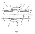
- the gas supply device 6 is in FIG. 2 in a schematic Section view shown.
- the gas supply line 8 may be a mixing line of the gas burner 1.
- a gaseous fuel such as natural gas, city gas, LPG or the like is mixed with primary air.
- the gaseous fuel flowing through the gas supply line 8 is marked with an arrow 9.
- the gas supply line 8 has at least one radial opening 10.
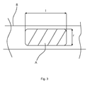
- the radial opening 10 has, as in the FIG. 3 shown, a cross-sectional area A on.
- two opposing radial openings 10, 11 are provided on the gas supply line 8.
- the openings 10, 11 are preferably formed rectangular with rounded corners. In the following, only the opening 10 will be discussed for the sake of simplicity.
- the opening 10 has, for example, a length I and a width r.
- the opening 10 Through the radial opening 10 primary air can flow into the gas supply line 8 and mix with the gaseous fuel located there.
- the inflow of the primary air through the opening 10 is in the FIG. 2 illustrated by an arrow 12.
- a higher or lower volume flow of primary air is required.
- the volume flow of primary air through the opening 10 is dependent on the size of the cross-sectional area A.
- the opening 10 may be completely or partially covered with a covering device 13.
- the covering device 13 is adapted to change the cross-sectional area A of the radial opening, in particular to reduce it.
- the cover device 13 may be configured to cover the radial opening 10 completely or only partially.
- the radial opening 10 may also be covered with a plurality of cover devices 13 arranged next to one another.
- the cover device 13 has a gripping portion 14, which is adapted to at least partially encompass the gas supply line 8 in a form-fitting manner and to cover the radial opening 10.
- the covering device 13 may have a sealing means which is arranged between the gripping section 14 and the gas supply line 8.
- the cover 13 is in the FIGS. 4 and 5 shown.
- the gripping portion 14 has a hollow cylindrical shape with a central axis 15.
- the Umgreifabites 14 may have two opposing interruptions of its wall.
- a handling portion 16 which is preferably formed integrally with the Umgreifabites 14 material.
- the handling section 16 preferably has an omega shape and merges into the wall of the encompassing section 14.
- the handling portion 16 is used to handle the cover 13 in a radial pushing them in the radial direction R on the gas supply line 8.
- a width b of the Umgreifabites 14 may be greater than the length I of the radial opening 10. Alternatively, the width b may be smaller than the length of the radial opening I.
- covering devices 13 with different widths b can be used for different types of fuel.
- the width b of the Umgreifabitess 14 is greater than the length I of the radial opening 10, the Umgreifabites 14, the radial opening 10 completely cover.
- the handling section 16 preferably has the same width as the width b of the encompassing section 14.
- the handling section 16 is preferably elastically deformable.
- an insertion section 17 of the cover 13 may be provided.
- the insertion section 17 preferably has two insertion arms 18, 19.
- the insertion arms 18, 19 are curved with their end portions facing away from each other.
- the insertion section 17 is preferably formed in one piece with the gripping portion 14.
- the insertion arms 18, 19 are adapted to move away from each other with a radial sliding of the cover 13 in the direction R to the gas supply line 8, wherein the handling portion 16, the Umgreifabites 14 and / or the insertion arms 18, 19 are elastically deformed.
- the covering device 13 is designed in particular as a sheet-metal bending component.
- the cover 13 has a spring steel. That is, the cover 13 is completely or partially formed with a spring steel. This results in good retention properties of the cover 13, since this encloses the gas supply line 8.
- the cover device 13 may further comprise an anti-rotation element 20.
- the anti-rotation element 20 may be adapted to fit into the radial opening 10 of the Engage gas supply line 8 to prevent twisting of the cover 13 relative to the gas supply line 8.
- the anti-rotation element 20 can engage, for example, in a protrusion or rib provided on an outer side of the gas supply line 8.
- the cover 13 has two anti-rotation elements 20, 21. Depending on whether the gas supply line has one or two openings 10, 11, accordingly, the cover 13 has one or two anti-rotation elements 20, 21.
- the anti-rotation element 20 is preferably located on an edge of the radial opening 10
- the anti-rotation element 21 is preferably located on an edge of the radial opening 11 such that the cover 13 is secured relative to a central axis 22 of the gas supply line 8 against rotation.
- the anti-rotation elements 20, 21 are preferably formed integrally with the Umgreifabites 14.
- the anti-rotation elements 20, 21 extend out of the encompassing section 14 in the direction of the central axis 15 thereof or in the direction of the gas supply line 8.
- the anti-rotation elements 20, 21 are preferably formed as folds of Umgreifabitess 14. That is, the anti-rotation elements 20, 21 are perpendicular to the Umgreifabites 14 deformed portions thereof.
- perpendicular is meant an angle of 90 ° ⁇ 10 °, preferably 90 ° ⁇ 5 °, more preferably 90 ° ⁇ 1 °.
- the covering device 13 has the encompassing section 14 which is adapted to at least partially embrace the gas supply line 8 in a form-fitting manner and to cover the radial opening 10. At the encompassing portion 14 of the handling portion 16 for handling the cover 13 is arranged at a radial sliding of the same on the gas supply line 8. All other elements explained above are merely optional components of the cover device 13.
- a gas cooking point 23 has a gas burner 1 as described above and a gas supply device 7 as described above.
Landscapes
- Engineering & Computer Science (AREA)
- Chemical & Material Sciences (AREA)
- Combustion & Propulsion (AREA)
- Mechanical Engineering (AREA)
- General Engineering & Computer Science (AREA)
- Feeding And Controlling Fuel (AREA)
- Gas Burners (AREA)
Description
- Die vorliegende Erfindung betrifft eine Abdeckeinrichtung zum Abdecken einer radialen Öffnung in einer Gaszufuhrleitung für einen Gasbrenner, eine Gaszufuhreinrichtung für einen Gasbrenner und eine Kochstelle.
- Um eine vollständige Gasverbrennung zu erreichen, wird in eine Gaszufuhrleitung eines Gasbrenners Primärluft eingespeist. Hierzu kann an der Gaszufuhrleitung eine radiale Öffnung vorgesehen sein. Je nach dem verwendeten Gas, wie beispielsweise Propangas oder Stadtgas ist ein unterschiedlicher Volumenstrom an Primärluft erforderlich. Damit der Gasbrenner für verschiedene Gasarten einsetzbar ist, ist eine Querschnittsfläche der radialen Öffnung einstellbar. Hierzu kann die radiale Öffnung entsprechend der erforderlichen Menge an Primärluft geöffnet, teilweise abgedeckt oder vollständig verschlossen werden. Dies kann beispielsweise durch geschlitzte zylindrische Hülsen erreicht werden, die federvorgespannt sind und die auf die Gaszufuhrleitung aufgebracht werden, um die radiale Öffnung teilweise oder vollständig zu verschließen.
- Vor diesem Hintergrund besteht eine Aufgabe der vorliegenden Erfindung darin, eine verbesserte und leicht handhabbare Abdeckeinrichtung zum Abdecken einer Öffnung in einer Gaszufuhrleitung zur Verfügung zu stellen.
- Demgemäß wird eine Abdeckeinrichtung zum Abdecken einer radialen Öffnung in einer Gaszufuhrleitung für einen Gasbrenner vorgeschlagen, mit einem Umgreifabschnitt, der dazu eingerichtet ist, die Gaszufuhrleitung zumindest teilweise formschlüssig zu umgreifen und die radiale Öffnung abzudecken, und einem an dem Umgreifabschnitt angeordneten Handhabungsabschnitt zum Handhaben der Abdeckeinrichtung bei einem radialen Aufschieben der Abdeckeinrichtung auf die Gaszufuhrleitung.
- Die Abdeckeinrichtung ist dazu eingerichtet, eine Querschnittsfläche der radialen Öffnung der Gaszufuhrleitung zu verändern, insbesondere zu verkleinern. Mittels des Handhabungsabschnitts kann die Abdeckeinrichtung leicht und ohne Werkzeug radial auf die Gaszufuhrleitung aufgeschoben werden. Insbesondere ist der Umgreifabschnitt derart federvorgespannt, dass er beim Aufschieben auf die Gaszufuhrleitung aufgebogen wird und diese somit zumindest teilweise formschlüssig umgreift. Insbesondere ist in einem demontierten Zustand der Abdeckeinrichtung ein Innendurchmesser des Umgreifabschnitts kleiner als ein Außendurchmesser der Gaszufuhrleitung. Hierdurch kann eine Federvorspannung des Umgreifabschnitts erreicht werden. Die Abdeckeinrichtung kann bei einem in eine Kochstelle eingebauten Gasbrenner schnell und komfortabel montiert, demontiert oder ausgetauscht werden. Hierdurch ist eine hohe Flexibilität bei dem verwendeten Brennstoff erreichbar. Vorzugsweise sind die Gaszufuhrleitung und der Umgreifabschnitt derart ausgestaltet, dass der Umgreifabschnitt eine radiale Haltekraft in Richtung zu der Gaszufuhrleitung ausübt. Zwischen dem Umgreifabschnitt und der Zufuhrleitung kann ein Dichtmittel vorgesehen sein. Alle Elemente der nachfolgend erläuterten Ausführungsformen der Abdeckeinrichtung sind lediglich optional.
- Gemäß einer Ausführungsform weist die Abdeckeinrichtung ein Verdrehsicherungselement auf, welches dazu eingerichtet ist, ein Verdrehen der Abdeckeinrichtung relativ zu der Gaszufuhrleitung zu verhindern.
- Vorzugsweise weist die Abdeckeinrichtung zwei Verdrehsicherungselemente auf. Die Verdrehsicherungselemente können beispielsweise in an einer Außenseite der Gaszufuhrleitung vorgesehene Bohrungen, Rippen, Vorwölbungen oder dergleichen formschlüssig eingreifen. Durch das Verdrehsicherungselement ist eine wohldefinierte Positionierung der Abdeckeinrichtung an der Gaszufuhrleitung gewährleistet. Das Verdrehsicherungselement ermöglicht einen einfachen Einbau der Abdeckeinrichtung, da sich diese mittels des Verdrehsicherungselements selbsttätig an der Gaszufuhrleitung positioniert.
- Gemäß einer weiteren Ausführungsform ist das Verdrehsicherungselement dazu eingerichtet, in die radiale Öffnung der Gaszufuhrleitung einzugreifen, um ein Verdrehen der Abdeckeinrichtung relativ zu der Gaszufuhrleitung zu verhindern.
- Vorzugsweise weist die Abdeckeinrichtung zwei Verdrehsicherungselemente auf, die in einander gegenüberliegende radiale Öffnungen der Gaszufuhrleitung eingreifen.
- Insbesondere greift das Verdrehsicherungselement formschlüssig in die radiale Öffnung ein. Das Verdrehsicherungselement gewährleistet eine bessere Abdichtung der radialen Öffnung.
- Gemäß einer weiteren Ausführungsform erstreckt sich das Verdrehsicherungselement aus dem Umgreifabschnitt heraus in Richtung zu der Gaszufuhrleitung hin.
- Der Umgreifabschnitt weist beispielsweise eine Zylinderform mit einem umlaufenden Wandabschnitt aus, aus dem sich das Verdrehsicherungselement heraus erstreckt. Das Verdrehsicherungselement erstreckt sich vorzugsweise zu einer Mittelachse des zylindrischen Umgreifabschnitts hin. Das Verdrehsicherungselement kann beispielsweise als Abkantung des Umgreifabschnitts ausgebildet sein. Das Verdrehsicherungselement ist insbesondere materialeinstückig mit dem Umgreifabschnitt ausgebildet. Dadurch, dass das Verdrehsicherungselement vorzugsweise als Abkantung des Umgreifabschnitts ausgebildet ist, ist eine einfache und kostengünstige Herstellung der Abdeckeinrichtung möglich.
- Gemäß einer weiteren Ausführungsform sind der Umgreifabschnitt und der Handhabungsabschnitt materialeinstückig ausgebildet.
- Vorzugsweise ist die Abdeckeinrichtung mit einem Metallwerkstoff gebildet. Das heißt, die Abdeckeinrichtung ist teilweise oder vollständig aus Metall gefertigt. Insbesondere ist die Abdeckeinrichtung ein Blechbiegebauteil. Hierdurch ergeben sich geringe Herstellkosten. Denkbar sind auch Kunststoffmaterialien.
- Gemäß einer weiteren Ausführungsform weist die Abdeckeinrichtung einen an dem Umgreifabschnitt angeordneten Einführabschnitt zum Einführen der Gaszufuhrleitung in den Umgreifabschnitt auf.
- Der Einführabschnitt weist vorzugsweise zwei abgeschrägte Einführarme auf. Der Einführabschnitt ist vorzugsweise gegenüberliegend dem Handhabungsabschnitt an dem Umgreifabschnitt angeordnet. Der Einführabschnitt ist dazu eingerichtet, ein radiales Aufschieben der Abdeckeinrichtung auf die Gaszufuhrleitung zu ermöglichen. Hierdurch wird eine gute und einfache Montierbarkeit der Abdeckeinrichtung an der Gaszufuhrleitung erreicht.
- Gemäß einer weiteren Ausführungsform sind der Umgreifabschnitt und der Einführabschnitt materialeinstückig ausgebildet.
- Hierdurch ergeben sich geringe Herstellkosten bei der Fertigung der Abdeckeinrichtung.
- Gemäß einer weiteren Ausführungsform ist der Handhabungsabschnitt elastisch verformbar.
- Der Handhabungsabschnitt kann beim Aufschieben der Abdeckeinrichtung auf die Gaszufuhrleitung elastisch verformt werden. Alternativ oder zusätzlich können der Einführabschnitt und/oder der Umgreifabschnitt elastisch verformbar sein. Dies ermöglicht eine komfortable Montage der Abdeckeinrichtung.
- Gemäß einer weiteren Ausführungsform ist die Abdeckeinrichtung als Blechbiegebauteil ausgebildet.
- Die Herstellung als Blechbiegebauteil ist einfach, kostengünstig und kann in hohen Stückzahlen erfolgen. Die Abdeckeinrichtung kann aus Federstahl gefertigt sein.
- Weiterhin wird eine Gaszufuhreinrichtung für einen Gasbrenner, mit einer Gaszufuhrleitung, die eine radiale Öffnung aufweist, und einer derartigen Abdeckeinrichtung vorgeschlagen.
- Weiterhin wird eine Kochstelle mit einem Gasbrenner und einer derartigen Gaszufuhreinrichtung vorgeschlagen.
- Weitere mögliche Implementierungen der Erfindung umfassen auch nicht explizit genannte Kombinationen von zuvor oder im Folgenden bezüglich der Ausführungsbeispiele beschriebenen Merkmale oder Ausführungsformen. Dabei wird der Fachmann auch Einzelaspekte als Verbesserungen oder Ergänzungen zu der jeweiligen Grundform der Erfindung hinzufügen.
- Weitere vorteilhafte Ausgestaltungen und Aspekte der Erfindung sind Gegenstand der Unteransprüche sowie der im Folgenden beschriebenen Ausführungsbeispiele der Erfindung. Im Weiteren wird die Erfindung anhand von bevorzugten Ausführungsformen unter Bezugnahme auf die beigelegten Figuren näher erläutert.
-
Fig. 1 zeigt eine schematische perspektivische Ansicht eines Gasbrenners; -
Fig. 2 zeigt eine schematische Schnittansicht einer Gaszufuhrleitung des Gasbrenners gemäß derFig. 1 ; -
Fig. 3 zeigt eine schematische Aufsicht der Gaszufuhrleitung gemäß derFig. 2 ; -
Fig. 4 zeigt eine schematische Seitenansicht einer Abdeckeinrichtung zum Abdecken einer radialen Öffnung in der Gaszufuhrleitung gemäß derFig. 2 ; und -
Fig. 5 zeigt eine schematische perspektivische Ansicht der Abdeckeinrichtung gemäß derFig. 4 . - In den Figuren sind gleiche oder funktionsgleiche Elemente mit denselben Bezugszeichen versehen worden, sofern nichts anderes angegeben ist.
- Die
Figur 1 zeigt eine schematische perspektivische Ansicht eines Gasbrenners 1. Der Gasbrenner 1 kann einen Innenbrenner 2 und einen Außenbrenner 3 aufweisen. Der Innenbrenner 2 kann in dem Außenbrenner 3 aufgenommen sein. Der Gasbrenner 1 weist ferner eine Zündeinrichtung 4 und ein Brennerhaus oder Gehäuse 5 auf. Der Gasbrenner 1 kann eine Gaszufuhreinrichtung 6 des Innenbrenners 2 und eine Gaszufuhreinrichtung 7 des Außenbrenners 3 aufweisen. Im Folgenden wird lediglich auf die Gaszufuhreinrichtung 6 des Innenbrenners 2 eingegangen. Die Gaszufuhreinrichtung 7 des Außenbrenners 3 kann analog zu der Gaszufuhreinrichtung 6 des Innenbrenners 2 ausgebildet sein. - Die Gaszufuhreinrichtung 6 weist eine Gaszufuhrleitung 8 auf. Die Gaszufuhrleitung 8 ist vorzugsweise rohrförmig. Die Gaszufuhreinrichtung 6 ist in
Figur 2 in einer schematischen Schnittansicht gezeigt. Die Gaszufuhrleitung 8 kann eine Mischleitung des Gasbrenners 1 sein. In der Gaszufuhrleitung 8 wird ein gasförmiger Brennstoff wie beispielsweise Erdgas, Stadtgas, Flüssiggas oder dergleichen mit Primärluft vermischt. In derFigur 2 ist der durch die Gaszufuhrleitung 8 strömende gasförmige Brennstoff mit einem Pfeil 9 gekennzeichnet. - Die Gaszufuhrleitung 8 weist zumindest eine radiale Öffnung 10 auf. Die radiale Öffnung 10 weist, wie in der
Figur 3 gezeigt, eine Querschnittsfläche A auf. Vorzugsweise sind an der Gaszufuhrleitung 8 zwei einander gegenüberliegende radiale Öffnungen 10, 11 vorgesehen. Die Öffnungen 10, 11 sind vorzugsweise rechteckförmig mit abgerundeten Ecken ausgebildet. Im Folgenden wird zur Vereinfachung lediglich auf die Öffnung 10 eingegangen. Die Öffnung 10 weist beispielsweise eine Länge I und eine Breite r auf. - Durch die radiale Öffnung 10 kann Primärluft in die Gaszufuhrleitung 8 strömen und sich mit dem dort befindlichen gasförmigen Brennstoff mischen. Das Einströmen der Primärluft durch die Öffnung 10 ist in der
Figur 2 mittels eines Pfeils 12 illustriert. Je nach der Art des verwendeten Brennstoffs ist ein höherer oder ein geringerer Volumenstrom an Primärluft erforderlich. Der Volumenstrom an Primärluft durch die Öffnung 10 ist abhängig von der Größe der Querschnittsfläche A. Um die Menge an einströmender Primärluft zu steuern, kann die Öffnung 10 mit einer Abdeckeinrichtung 13 vollständig oder teilweise abgedeckt sein. Die Abdeckeinrichtung 13 ist dazu eingerichtet, die Querschnittsfläche A der radialen Öffnung zu ändern, insbesondere zu verkleinern. - Die Abdeckeinrichtung 13 kann dazu eingerichtet sein, die radiale Öffnung 10 vollständig oder lediglich teilweise abzudecken. Die radiale Öffnung 10 kann auch mit mehreren nebeneinander angeordneten Abdeckeinrichtungen 13 abgedeckt sein. Die Abdeckeinrichtung 13 weist einen Umgreifabschnitt 14 auf, der dazu eingerichtet ist, die Gaszufuhrleitung 8 zumindest teilweise formschlüssig zu umgreifen und die radiale Öffnung 10 abzudecken. Die Abdeckeinrichtung 13 kann ein Dichtmittel aufweisen, das zwischen dem Umgreifabschnitt 14 und der Gaszufuhrleitung 8 angeordnet ist.
- Die Abdeckeinrichtung 13 ist in den
Figuren 4 und 5 gezeigt. Der Umgreifabschnitt 14 weist eine hohlzylindrische Form mit einer Mittelachse 15 auf. Der Umgreifabschnitt 14 kann zwei einander gegenüberliegende Unterbrechungen seiner Wandung aufweisen. An dem Umgreifabschnitt 14 angeordnet ist ein Handhabungsabschnitt 16, der vorzugsweise materialeinstückig mit dem Umgreifabschnitt 14 ausgebildet ist. Der Handhabungsabschnitt 16 weist bevorzugt eine Omegaform auf und geht in die Wandung des Umgreifabschnitts 14 über. Der Handhabungsabschnitt 16 dient dem Handhaben der Abdeckeinrichtung 13 bei einem radialen Aufschieben derselben in radialer Richtung R auf die Gaszufuhrleitung 8. Man kann bei der Abdeckeinrichtung 13 von einem Clips oder einer Klammer sprechen, die zum Umklammern der Gaszufuhrleitung 8 dient. Eine Breite b des Umgreifabschnitts 14 kann größer sein als die Länge I der radialen Öffnung 10. Alternativ kann die Breite b kleiner als die Länge der radialen Öffnung I sein. Beispielsweise können für verschiedene Brennstofftypen Abdeckeinrichtungen 13 mit verschiedenen Breiten b eingesetzt werden. - Falls in Ausführungsformen der Abdeckeinrichtung 13 die Breite b des Umgreifabschnitts 14 größer ist als die Länge I der radialen Öffnung 10, kann der Umgreifabschnitt 14 die radiale Öffnung 10 vollständig abdecken. Der Handhabungsabschnitt 16 weist vorzugsweise die gleiche Breite auf wie die Breite b des Umgreifabschnitts 14. Der Handhabungsabschnitt 16 ist vorzugsweise elastisch verformbar.
- Gegenüberliegend dem Handhabungsabschnitt 16 kann ein Einführabschnitt 17 der Abdeckeinrichtung 13 vorgesehen sein. Der Einführabschnitt 17 weist vorzugsweise zwei Einführarme 18, 19 auf. Die Einführarme 18, 19 sind gekrümmt, wobei deren Endabschnitte voneinander weg weisen. Der Einführabschnitt 17 ist vorzugsweise materialeinstückig mit dem Umgreifabschnitt 14 ausgebildet. Die Einführarme 18, 19 sind dazu eingerichtet, dass diese sich bei einem radialen Aufschieben der Abdeckeinrichtung 13 in Richtung R zu der Gaszufuhrleitung 8 voneinander weg bewegen, wobei der Handhabungsabschnitt 16, der Umgreifabschnitt 14 und/oder die Einführarme 18, 19 elastisch verformt werden. Die Abdeckeinrichtung 13 ist insbesondere als Blechbiegebauteil ausgeführt. Vorzugsweise weist die Abdeckeinrichtung 13 einen Federstahl auf. Das heißt, die Abdeckeinrichtung 13 ist vollständig oder teilweise mit einem Federstahl gebildet. Hierdurch ergeben sich gute Halteeigenschaften der Abdeckeinrichtung 13, da diese die Gaszufuhrleitung 8 umklammert.
- Die Abdeckeinrichtung 13 kann ferner ein Verdrehsicherungselement 20 aufweisen. Das Verdrehsicherungselement 20 kann dazu eingerichtet sein, in die radiale Öffnung 10 der Gaszufuhrleitung 8 einzugreifen, um ein Verdrehen der Abdeckeinrichtung 13 relativ zu der Gaszufuhrleitung 8 zu verhindern. Alternativ kann das Verdrehsicherungselement 20 beispielsweise in eine auf einer Außenseite der Gaszufuhrleitung 8 vorgesehene Vorwölbung oder Rippe eingreifen.
- Vorzugsweise weist die Abdeckeinrichtung 13 zwei Verdrehsicherungselemente 20, 21 auf. Je nachdem, ob die Gaszufuhrleitung eine oder zwei Öffnungen 10, 11 aufweist, weist entsprechend die Abdeckeinrichtung 13 ein oder zwei Verdrehsicherungselemente 20, 21 auf. Das Verdrehsicherungselement 20 liegt vorzugsweise an einem Rand der radialen Öffnung 10 auf, und das Verdrehsicherungselement 21 liegt vorzugsweise an einem Rand der radialen Öffnung 11 derart auf, dass die Abdeckeinrichtung 13 relativ zu einer Mittelachse 22 der Gaszufuhrleitung 8 gegen ein Verdrehen gesichert ist.
- Die Verdrehsicherungselemente 20, 21 sind vorzugsweise einteilig mit dem Umgreifabschnitt 14 ausgebildet. Die Verdrehsicherungselemente 20, 21 erstrecken sich aus dem Umgreifabschnitt 14 heraus in Richtung der Mittelachse 15 desselben bzw. in Richtung zu der Gaszufuhrleitung 8 hin. Die Verdrehsicherungselemente 20, 21 sind vorzugsweise als Abkantungen des Umgreifabschnitts 14 ausgebildet. Das heißt, die Verdrehsicherungselemente 20, 21 sind senkrecht zu dem Umgreifabschnitt 14 verformte Abschnitte desselben. Unter "senkrecht" ist vorliegend ein Winkel von 90° ± 10°, bevorzugt 90° ± 5°, weiter bevorzugt 90° ± 1° zu verstehen.
- Die Abdeckeinrichtung 13 weist den Umgreifabschnitt 14 auf, der dazu eingerichtet ist, die Gaszufuhrleitung 8 zumindest teilweise formschlüssig zu umgreifen und die radiale Öffnung 10 abzudecken. An dem Umgreifabschnitt 14 ist der Handhabungsabschnitt 16 zum Handhaben der Abdeckeinrichtung 13 bei einem radialen Aufschieben desselben auf die Gaszufuhrleitung 8 angeordnet. Alle weiteren zuvor erläuterten Elemente sind lediglich optionale Bestandteile der Abdeckeinrichtung 13.
- Eine Gaskochstelle 23 weist einen wie zuvor beschriebenen Gasbrenner 1 und eine wie zuvor beschriebene Gaszufuhreinrichtung 7 auf.
- Obwohl die vorliegende Erfindung anhand von Ausführungsbeispielen beschrieben wurde, ist sie vielfältig modifizierbar.
-
- 1
- Gasbrenner
- 2
- Innenbrenner
- 3
- Außenbrenner
- 4
- Zündeinrichtung
- 5
- Gehäuse
- 6
- Gaszufuhreinrichtung
- 7
- Gaszufuhreinrichtung
- 8
- Gaszufuhrleitung
- 9
- Pfeil
- 10
- Öffnung
- 11
- Öffnung
- 12
- Pfeil
- 13
- Abdeckeinrichtung
- 14
- Umgreifabschnitt
- 15
- Mittelachse
- 16
- Handhabungsabschnitt
- 17
- Einführabschnitt
- 18
- Einführarm
- 19
- Einführarm
- 20
- Verdrehsicherungselement
- 21
- Verdrehsicherungselement
- 22
- Mittelachse
- 23
- Gaskochstelle
- A
- Querschnittsfläche
- b
- Breite
- l
- Länge
- r
- Breite
- R
- Richtung
Claims (11)
- Abdeckeinrichtung (13) zum Abdecken einer radialen Öffnung (10, 11) in einer Gaszufuhrleitung (8) für einen Gasbrenner (1), mit einem Umgreifabschnitt (14), der dazu eingerichtet ist, die Gaszufuhrleitung (8) zumindest teilweise formschlüssig zu umgreifen und die radiale Öffnung (10, 11) abzudecken, und einem an dem Umgreifabschnitt (14) angeordneten Handhabungsabschnitt (16) zum Handhaben der Abdeckeinrichtung (13) bei einem radialen Aufschieben der Abdeckeinrichtung (13) auf die Gaszufuhrleitung (8).
- Abdeckeinrichtung nach Anspruch 1, gekennzeichnet durch ein Verdrehsicherungselement (20, 21), welches dazu eingerichtet ist, ein Verdrehen der Abdeckeinrichtung (13) relativ zu der Gaszufuhrleitung (8) zu verhindern.
- Abdeckeinrichtung nach Anspruch 2, dadurch gekennzeichnet, dass das Verdrehsicherungselement (20, 21) dazu eingerichtet ist, in die radiale Öffnung (10, 11) der Gaszufuhrleitung (8) einzugreifen, um ein Verdrehen der Abdeckeinrichtung (13) relativ zu der Gaszufuhrleitung (8) zu verhindern.
- Abdeckeinrichtung nach Anspruch 2 oder 3, dadurch gekennzeichnet, dass sich das Verdrehsicherungselement (20, 21) aus dem Umgreifabschnitt (14) heraus in Richtung zu der Gaszufuhrleitung (8) hin erstreckt.
- Abdeckeinrichtung nach einem der Ansprüche 1 - 4, dadurch gekennzeichnet, dass der Umgreifabschnitt (14) und der Handhabungsabschnitt (16) materialeinstückig ausgebildet sind.
- Abdeckeinrichtung nach einem der Ansprüche 1 - 5, gekennzeichnet durch einen an dem Umgreifabschnitt (14) angeordneten Einführabschnitt (17) zum Einführen der Gaszufuhrleitung (8) in den Umgreifabschnitt (14).
- Abdeckeinrichtung nach Anspruch 6, dadurch gekennzeichnet, dass der Umgreifabschnitt (14) und der Einführabschnitt (17) materialeinstückig ausgebildet sind.
- Abdeckeinrichtung nach einem der Ansprüche 1 - 7, dadurch gekennzeichnet, dass der Handhabungsabschnitt (16) elastisch verformbar ist.
- Abdeckeinrichtung nach einem der Ansprüche 1 - 8, dadurch gekennzeichnet, dass die Abdeckeinrichtung (13) als Blechbiegebauteil ausgebildet ist.
- Gaszufuhreinrichtung (6, 7) für einen Gasbrenner (1), mit einer Gaszufuhrleitung (8), die eine radiale Öffnung (10, 11) aufweist, und einer Abdeckeinrichtung (13) nach einem der Ansprüche 1 - 9.
- Kochstelle (23) mit einem Gasbrenner (1) und einer Gaszufuhreinrichtung (6, 7) nach Anspruch 9.
Applications Claiming Priority (1)
| Application Number | Priority Date | Filing Date | Title |
|---|---|---|---|
| ES201331247 | 2013-08-09 |
Publications (3)
| Publication Number | Publication Date |
|---|---|
| EP2835581A2 true EP2835581A2 (de) | 2015-02-11 |
| EP2835581A3 EP2835581A3 (de) | 2015-02-25 |
| EP2835581B1 EP2835581B1 (de) | 2018-03-14 |
Family
ID=51225328
Family Applications (1)
| Application Number | Title | Priority Date | Filing Date |
|---|---|---|---|
| EP14178299.5A Active EP2835581B1 (de) | 2013-08-09 | 2014-07-24 | Gaszufuhreinrichtung für einen Gasbrenner mit einer Abdeckeinrichtung zum Abdecken einer radialen Öffnung in einer Gaszufuhrleitung für einen Gasbrenner und Kochstelle |
Country Status (3)
| Country | Link |
|---|---|
| EP (1) | EP2835581B1 (de) |
| CN (1) | CN104344418B (de) |
| ES (1) | ES2664987T3 (de) |
Cited By (2)
| Publication number | Priority date | Publication date | Assignee | Title |
|---|---|---|---|---|
| WO2017051364A3 (en) * | 2015-09-24 | 2017-10-26 | Defendi Italy S.R.L. | A gas burner with multiple rings of flames for cooking hobs |
| CN108139073A (zh) * | 2015-04-24 | 2018-06-08 | 德芬迪意大利有限责任公司 | 用于烹饪灶具的具有多个火焰环的燃气燃烧器 |
Family Cites Families (11)
| Publication number | Priority date | Publication date | Assignee | Title |
|---|---|---|---|---|
| GB142159A (de) * | ||||
| US1406614A (en) * | 1920-04-30 | 1922-02-14 | Thomas W Corkell | Regulator for gas-heater burners |
| GB182952A (en) * | 1921-04-18 | 1922-07-18 | John Smith | Improvements in or relating to incandescent gas burners |
| US2494881A (en) * | 1945-07-03 | 1950-01-17 | Prestole Corp | Fastening device for condensers or the like |
| US3351118A (en) * | 1966-06-20 | 1967-11-07 | Midland Ross Corp | Means for supplying air to a gas burner |
| US3905756A (en) * | 1974-05-09 | 1975-09-16 | Lincoln Brass Works | Shutter structure and mixing tube assembly for gas burner |
| US4686957A (en) * | 1984-10-30 | 1987-08-18 | Modern Home Products Corp. | Gas nozzle attachment |
| JPS61272518A (ja) * | 1985-05-25 | 1986-12-02 | Nakajima Doukoushiyo:Kk | 液化ガスを用いた熱加工装置 |
| EP0309950B1 (de) * | 1987-09-28 | 1993-06-02 | Joh. Vaillant GmbH u. Co. | Atmosphärischer Gasbrenner |
| CN202209683U (zh) * | 2011-08-09 | 2012-05-02 | 北京市燃气集团有限责任公司 | 燃气灶具喷嘴同轴度柔性调整机构 |
| CN202792021U (zh) * | 2012-07-20 | 2013-03-13 | 陈开银 | 猛火节能燃气炉头 |
-
2014
- 2014-07-24 ES ES14178299.5T patent/ES2664987T3/es active Active
- 2014-07-24 EP EP14178299.5A patent/EP2835581B1/de active Active
- 2014-08-08 CN CN201410388175.4A patent/CN104344418B/zh active Active
Non-Patent Citations (1)
| Title |
|---|
| None |
Cited By (4)
| Publication number | Priority date | Publication date | Assignee | Title |
|---|---|---|---|---|
| CN108139073A (zh) * | 2015-04-24 | 2018-06-08 | 德芬迪意大利有限责任公司 | 用于烹饪灶具的具有多个火焰环的燃气燃烧器 |
| CN108139073B (zh) * | 2015-04-24 | 2019-09-17 | 德芬迪意大利有限责任公司 | 用于烹饪灶具的具有多个火焰环的燃气燃烧器 |
| WO2017051364A3 (en) * | 2015-09-24 | 2017-10-26 | Defendi Italy S.R.L. | A gas burner with multiple rings of flames for cooking hobs |
| US10584871B2 (en) | 2015-09-24 | 2020-03-10 | Defendi Italy S.R.L. | Gas burner with multiple rings of flames for cooking hobs |
Also Published As
| Publication number | Publication date |
|---|---|
| CN104344418A (zh) | 2015-02-11 |
| CN104344418B (zh) | 2018-03-30 |
| EP2835581B1 (de) | 2018-03-14 |
| ES2664987T3 (es) | 2018-04-24 |
| EP2835581A3 (de) | 2015-02-25 |
Similar Documents
| Publication | Publication Date | Title |
|---|---|---|
| DE2201317A1 (de) | Waermespeichernder boiler | |
| EP1959194B1 (de) | Mischeinrichtung für einen Gasgebläsebrenner | |
| EP2835581B1 (de) | Gaszufuhreinrichtung für einen Gasbrenner mit einer Abdeckeinrichtung zum Abdecken einer radialen Öffnung in einer Gaszufuhrleitung für einen Gasbrenner und Kochstelle | |
| DE102012112852B4 (de) | Rohrbogen zur Abgasführung in Heizungsanlagen | |
| WO2013175350A2 (de) | Gasbeheiztes gargerät | |
| DE102017129884B4 (de) | Verstellbare Drallerzeugungseinrichtung für Verdichter | |
| DE3831624A1 (de) | Gasbrenner | |
| EP3047135A1 (de) | Niederhalter für eine brennstoffeinspritzvorrichtung | |
| DE102013103534B4 (de) | "Steckverbindungsteil für einen Leitungsverbinder, insbesondere für eine konfektionierte Medienleitung" | |
| DE19536441A1 (de) | Federklammer zur Verbindung einer Einspritzdüse mit einer Einspritzleitung | |
| EP2444709B1 (de) | Kupplungsmuffe | |
| EP0617244B1 (de) | Luftheizgerät | |
| DE112009001436B4 (de) | Luftführungsanordnung in einem Ansaugsystem für die Verbrennungsluft einer Brennkraftmaschine | |
| DE20022107U1 (de) | Vorrichtung für den Einsatz in Abgasanlagen | |
| AT14653U1 (de) | Schutzmanschette zur Abdichtung einer Anschlussleitung an einem Gehäuse | |
| DE102013008773A1 (de) | Wärmetauscher, insbesondere Abgaswärmetauscher oder Ladeluftkühler | |
| DE10103384C2 (de) | Abgasleitung für Brenngeräte in Gebäuden | |
| EP2933558B1 (de) | Windabweisersystem | |
| EP4650684A1 (de) | Heizgerät mit einer rohranschlussaufnahme | |
| DE102010007083A1 (de) | Vorrichtung für den dachseitigen Abschluss einer Rohrleitung | |
| DE202005005640U1 (de) | Wirbulatoreinsatz für in Heizkesselgehäusen angeordnete Heizgaszugrohre | |
| EP2153135A1 (de) | Raumluftbefeuchter | |
| DE102004044445B4 (de) | Gasbeheiztes Wärmegerät | |
| DE102004041818B4 (de) | Gasbeheizter Warmwasserbereiter | |
| EP2863121B1 (de) | Düse für einen Gasbrenner |
Legal Events
| Date | Code | Title | Description |
|---|---|---|---|
| PUAL | Search report despatched |
Free format text: ORIGINAL CODE: 0009013 |
|
| PUAI | Public reference made under article 153(3) epc to a published international application that has entered the european phase |
Free format text: ORIGINAL CODE: 0009012 |
|
| 17P | Request for examination filed |
Effective date: 20140724 |
|
| AK | Designated contracting states |
Kind code of ref document: A2 Designated state(s): AL AT BE BG CH CY CZ DE DK EE ES FI FR GB GR HR HU IE IS IT LI LT LU LV MC MK MT NL NO PL PT RO RS SE SI SK SM TR |
|
| AX | Request for extension of the european patent |
Extension state: BA ME |
|
| AK | Designated contracting states |
Kind code of ref document: A3 Designated state(s): AL AT BE BG CH CY CZ DE DK EE ES FI FR GB GR HR HU IE IS IT LI LT LU LV MC MK MT NL NO PL PT RO RS SE SI SK SM TR |
|
| AX | Request for extension of the european patent |
Extension state: BA ME |
|
| RIC1 | Information provided on ipc code assigned before grant |
Ipc: F23D 14/64 20060101AFI20150121BHEP |
|
| RAP1 | Party data changed (applicant data changed or rights of an application transferred) |
Owner name: BSH HAUSGERAETE GMBH |
|
| R17P | Request for examination filed (corrected) |
Effective date: 20150825 |
|
| RBV | Designated contracting states (corrected) |
Designated state(s): AL AT BE BG CH CY CZ DE DK EE ES FI FR GB GR HR HU IE IS IT LI LT LU LV MC MK MT NL NO PL PT RO RS SE SI SK SM TR |
|
| 17Q | First examination report despatched |
Effective date: 20160223 |
|
| GRAP | Despatch of communication of intention to grant a patent |
Free format text: ORIGINAL CODE: EPIDOSNIGR1 |
|
| INTG | Intention to grant announced |
Effective date: 20170929 |
|
| GRAS | Grant fee paid |
Free format text: ORIGINAL CODE: EPIDOSNIGR3 |
|
| GRAA | (expected) grant |
Free format text: ORIGINAL CODE: 0009210 |
|
| AK | Designated contracting states |
Kind code of ref document: B1 Designated state(s): AL AT BE BG CH CY CZ DE DK EE ES FI FR GB GR HR HU IE IS IT LI LT LU LV MC MK MT NL NO PL PT RO RS SE SI SK SM TR |
|
| REG | Reference to a national code |
Ref country code: GB Ref legal event code: FG4D Free format text: NOT ENGLISH |
|
| REG | Reference to a national code |
Ref country code: CH Ref legal event code: EP Ref country code: AT Ref legal event code: REF Ref document number: 979264 Country of ref document: AT Kind code of ref document: T Effective date: 20180315 |
|
| REG | Reference to a national code |
Ref country code: IE Ref legal event code: FG4D Free format text: LANGUAGE OF EP DOCUMENT: GERMAN |
|
| REG | Reference to a national code |
Ref country code: DE Ref legal event code: R096 Ref document number: 502014007607 Country of ref document: DE |
|
| REG | Reference to a national code |
Ref country code: ES Ref legal event code: FG2A Ref document number: 2664987 Country of ref document: ES Kind code of ref document: T3 Effective date: 20180424 |
|
| REG | Reference to a national code |
Ref country code: NL Ref legal event code: MP Effective date: 20180314 |
|
| REG | Reference to a national code |
Ref country code: LT Ref legal event code: MG4D |
|
| PG25 | Lapsed in a contracting state [announced via postgrant information from national office to epo] |
Ref country code: CY Free format text: LAPSE BECAUSE OF FAILURE TO SUBMIT A TRANSLATION OF THE DESCRIPTION OR TO PAY THE FEE WITHIN THE PRESCRIBED TIME-LIMIT Effective date: 20180314 Ref country code: LT Free format text: LAPSE BECAUSE OF FAILURE TO SUBMIT A TRANSLATION OF THE DESCRIPTION OR TO PAY THE FEE WITHIN THE PRESCRIBED TIME-LIMIT Effective date: 20180314 Ref country code: HR Free format text: LAPSE BECAUSE OF FAILURE TO SUBMIT A TRANSLATION OF THE DESCRIPTION OR TO PAY THE FEE WITHIN THE PRESCRIBED TIME-LIMIT Effective date: 20180314 Ref country code: NO Free format text: LAPSE BECAUSE OF FAILURE TO SUBMIT A TRANSLATION OF THE DESCRIPTION OR TO PAY THE FEE WITHIN THE PRESCRIBED TIME-LIMIT Effective date: 20180614 Ref country code: FI Free format text: LAPSE BECAUSE OF FAILURE TO SUBMIT A TRANSLATION OF THE DESCRIPTION OR TO PAY THE FEE WITHIN THE PRESCRIBED TIME-LIMIT Effective date: 20180314 |
|
| PG25 | Lapsed in a contracting state [announced via postgrant information from national office to epo] |
Ref country code: RS Free format text: LAPSE BECAUSE OF FAILURE TO SUBMIT A TRANSLATION OF THE DESCRIPTION OR TO PAY THE FEE WITHIN THE PRESCRIBED TIME-LIMIT Effective date: 20180314 Ref country code: LV Free format text: LAPSE BECAUSE OF FAILURE TO SUBMIT A TRANSLATION OF THE DESCRIPTION OR TO PAY THE FEE WITHIN THE PRESCRIBED TIME-LIMIT Effective date: 20180314 Ref country code: SE Free format text: LAPSE BECAUSE OF FAILURE TO SUBMIT A TRANSLATION OF THE DESCRIPTION OR TO PAY THE FEE WITHIN THE PRESCRIBED TIME-LIMIT Effective date: 20180314 Ref country code: GR Free format text: LAPSE BECAUSE OF FAILURE TO SUBMIT A TRANSLATION OF THE DESCRIPTION OR TO PAY THE FEE WITHIN THE PRESCRIBED TIME-LIMIT Effective date: 20180615 Ref country code: BG Free format text: LAPSE BECAUSE OF FAILURE TO SUBMIT A TRANSLATION OF THE DESCRIPTION OR TO PAY THE FEE WITHIN THE PRESCRIBED TIME-LIMIT Effective date: 20180614 |
|
| PG25 | Lapsed in a contracting state [announced via postgrant information from national office to epo] |
Ref country code: MT Free format text: LAPSE BECAUSE OF FAILURE TO SUBMIT A TRANSLATION OF THE DESCRIPTION OR TO PAY THE FEE WITHIN THE PRESCRIBED TIME-LIMIT Effective date: 20180314 |
|
| PG25 | Lapsed in a contracting state [announced via postgrant information from national office to epo] |
Ref country code: AL Free format text: LAPSE BECAUSE OF FAILURE TO SUBMIT A TRANSLATION OF THE DESCRIPTION OR TO PAY THE FEE WITHIN THE PRESCRIBED TIME-LIMIT Effective date: 20180314 Ref country code: EE Free format text: LAPSE BECAUSE OF FAILURE TO SUBMIT A TRANSLATION OF THE DESCRIPTION OR TO PAY THE FEE WITHIN THE PRESCRIBED TIME-LIMIT Effective date: 20180314 Ref country code: PL Free format text: LAPSE BECAUSE OF FAILURE TO SUBMIT A TRANSLATION OF THE DESCRIPTION OR TO PAY THE FEE WITHIN THE PRESCRIBED TIME-LIMIT Effective date: 20180314 Ref country code: NL Free format text: LAPSE BECAUSE OF FAILURE TO SUBMIT A TRANSLATION OF THE DESCRIPTION OR TO PAY THE FEE WITHIN THE PRESCRIBED TIME-LIMIT Effective date: 20180314 Ref country code: RO Free format text: LAPSE BECAUSE OF FAILURE TO SUBMIT A TRANSLATION OF THE DESCRIPTION OR TO PAY THE FEE WITHIN THE PRESCRIBED TIME-LIMIT Effective date: 20180314 |
|
| PG25 | Lapsed in a contracting state [announced via postgrant information from national office to epo] |
Ref country code: SK Free format text: LAPSE BECAUSE OF FAILURE TO SUBMIT A TRANSLATION OF THE DESCRIPTION OR TO PAY THE FEE WITHIN THE PRESCRIBED TIME-LIMIT Effective date: 20180314 Ref country code: SM Free format text: LAPSE BECAUSE OF FAILURE TO SUBMIT A TRANSLATION OF THE DESCRIPTION OR TO PAY THE FEE WITHIN THE PRESCRIBED TIME-LIMIT Effective date: 20180314 Ref country code: CZ Free format text: LAPSE BECAUSE OF FAILURE TO SUBMIT A TRANSLATION OF THE DESCRIPTION OR TO PAY THE FEE WITHIN THE PRESCRIBED TIME-LIMIT Effective date: 20180314 |
|
| REG | Reference to a national code |
Ref country code: DE Ref legal event code: R097 Ref document number: 502014007607 Country of ref document: DE |
|
| PG25 | Lapsed in a contracting state [announced via postgrant information from national office to epo] |
Ref country code: PT Free format text: LAPSE BECAUSE OF FAILURE TO SUBMIT A TRANSLATION OF THE DESCRIPTION OR TO PAY THE FEE WITHIN THE PRESCRIBED TIME-LIMIT Effective date: 20180716 |
|
| PLBE | No opposition filed within time limit |
Free format text: ORIGINAL CODE: 0009261 |
|
| STAA | Information on the status of an ep patent application or granted ep patent |
Free format text: STATUS: NO OPPOSITION FILED WITHIN TIME LIMIT |
|
| PG25 | Lapsed in a contracting state [announced via postgrant information from national office to epo] |
Ref country code: DK Free format text: LAPSE BECAUSE OF FAILURE TO SUBMIT A TRANSLATION OF THE DESCRIPTION OR TO PAY THE FEE WITHIN THE PRESCRIBED TIME-LIMIT Effective date: 20180314 |
|
| 26N | No opposition filed |
Effective date: 20181217 |
|
| PG25 | Lapsed in a contracting state [announced via postgrant information from national office to epo] |
Ref country code: SI Free format text: LAPSE BECAUSE OF FAILURE TO SUBMIT A TRANSLATION OF THE DESCRIPTION OR TO PAY THE FEE WITHIN THE PRESCRIBED TIME-LIMIT Effective date: 20180314 |
|
| REG | Reference to a national code |
Ref country code: CH Ref legal event code: PL |
|
| GBPC | Gb: european patent ceased through non-payment of renewal fee |
Effective date: 20180724 |
|
| PG25 | Lapsed in a contracting state [announced via postgrant information from national office to epo] |
Ref country code: MC Free format text: LAPSE BECAUSE OF FAILURE TO SUBMIT A TRANSLATION OF THE DESCRIPTION OR TO PAY THE FEE WITHIN THE PRESCRIBED TIME-LIMIT Effective date: 20180314 Ref country code: LU Free format text: LAPSE BECAUSE OF NON-PAYMENT OF DUE FEES Effective date: 20180724 |
|
| REG | Reference to a national code |
Ref country code: BE Ref legal event code: MM Effective date: 20180731 |
|
| REG | Reference to a national code |
Ref country code: IE Ref legal event code: MM4A |
|
| PG25 | Lapsed in a contracting state [announced via postgrant information from national office to epo] |
Ref country code: FR Free format text: LAPSE BECAUSE OF NON-PAYMENT OF DUE FEES Effective date: 20180731 Ref country code: LI Free format text: LAPSE BECAUSE OF NON-PAYMENT OF DUE FEES Effective date: 20180731 Ref country code: CH Free format text: LAPSE BECAUSE OF NON-PAYMENT OF DUE FEES Effective date: 20180731 Ref country code: GB Free format text: LAPSE BECAUSE OF NON-PAYMENT OF DUE FEES Effective date: 20180724 Ref country code: IE Free format text: LAPSE BECAUSE OF NON-PAYMENT OF DUE FEES Effective date: 20180724 |
|
| PG25 | Lapsed in a contracting state [announced via postgrant information from national office to epo] |
Ref country code: BE Free format text: LAPSE BECAUSE OF NON-PAYMENT OF DUE FEES Effective date: 20180731 |
|
| PG25 | Lapsed in a contracting state [announced via postgrant information from national office to epo] |
Ref country code: HU Free format text: LAPSE BECAUSE OF FAILURE TO SUBMIT A TRANSLATION OF THE DESCRIPTION OR TO PAY THE FEE WITHIN THE PRESCRIBED TIME-LIMIT; INVALID AB INITIO Effective date: 20140724 |
|
| PG25 | Lapsed in a contracting state [announced via postgrant information from national office to epo] |
Ref country code: MK Free format text: LAPSE BECAUSE OF NON-PAYMENT OF DUE FEES Effective date: 20180314 |
|
| PG25 | Lapsed in a contracting state [announced via postgrant information from national office to epo] |
Ref country code: IS Free format text: LAPSE BECAUSE OF FAILURE TO SUBMIT A TRANSLATION OF THE DESCRIPTION OR TO PAY THE FEE WITHIN THE PRESCRIBED TIME-LIMIT Effective date: 20180714 |
|
| REG | Reference to a national code |
Ref country code: AT Ref legal event code: MM01 Ref document number: 979264 Country of ref document: AT Kind code of ref document: T Effective date: 20190724 |
|
| PG25 | Lapsed in a contracting state [announced via postgrant information from national office to epo] |
Ref country code: AT Free format text: LAPSE BECAUSE OF NON-PAYMENT OF DUE FEES Effective date: 20190724 |
|
| REG | Reference to a national code |
Ref country code: DE Ref legal event code: R084 Ref document number: 502014007607 Country of ref document: DE |
|
| P01 | Opt-out of the competence of the unified patent court (upc) registered |
Effective date: 20230504 |
|
| PGFP | Annual fee paid to national office [announced via postgrant information from national office to epo] |
Ref country code: ES Payment date: 20230821 Year of fee payment: 10 |
|
| PGFP | Annual fee paid to national office [announced via postgrant information from national office to epo] |
Ref country code: DE Payment date: 20230731 Year of fee payment: 10 |
|
| REG | Reference to a national code |
Ref country code: DE Ref legal event code: R119 Ref document number: 502014007607 Country of ref document: DE |
|
| PG25 | Lapsed in a contracting state [announced via postgrant information from national office to epo] |
Ref country code: DE Free format text: LAPSE BECAUSE OF NON-PAYMENT OF DUE FEES Effective date: 20250201 |
|
| REG | Reference to a national code |
Ref country code: ES Ref legal event code: FD2A Effective date: 20250904 |
|
| PG25 | Lapsed in a contracting state [announced via postgrant information from national office to epo] |
Ref country code: ES Free format text: LAPSE BECAUSE OF NON-PAYMENT OF DUE FEES Effective date: 20240725 |
|
| PGFP | Annual fee paid to national office [announced via postgrant information from national office to epo] |
Ref country code: TR Payment date: 20250718 Year of fee payment: 12 Ref country code: IT Payment date: 20250731 Year of fee payment: 12 |