EP2835524A1 - System for recirculating engine exhaust gas - Google Patents
System for recirculating engine exhaust gas Download PDFInfo
- Publication number
- EP2835524A1 EP2835524A1 EP13772086.8A EP13772086A EP2835524A1 EP 2835524 A1 EP2835524 A1 EP 2835524A1 EP 13772086 A EP13772086 A EP 13772086A EP 2835524 A1 EP2835524 A1 EP 2835524A1
- Authority
- EP
- European Patent Office
- Prior art keywords
- exhaust gas
- manifold
- engine
- present disclosure
- cylinders
- Prior art date
- Legal status (The legal status is an assumption and is not a legal conclusion. Google has not performed a legal analysis and makes no representation as to the accuracy of the status listed.)
- Withdrawn
Links
Images



Classifications
-
- F—MECHANICAL ENGINEERING; LIGHTING; HEATING; WEAPONS; BLASTING
- F02—COMBUSTION ENGINES; HOT-GAS OR COMBUSTION-PRODUCT ENGINE PLANTS
- F02M—SUPPLYING COMBUSTION ENGINES IN GENERAL WITH COMBUSTIBLE MIXTURES OR CONSTITUENTS THEREOF
- F02M26/00—Engine-pertinent apparatus for adding exhaust gases to combustion-air, main fuel or fuel-air mixture, e.g. by exhaust gas recirculation [EGR] systems
- F02M26/13—Arrangement or layout of EGR passages, e.g. in relation to specific engine parts or for incorporation of accessories
- F02M26/42—Arrangement or layout of EGR passages, e.g. in relation to specific engine parts or for incorporation of accessories having two or more EGR passages; EGR systems specially adapted for engines having two or more cylinders
-
- F—MECHANICAL ENGINEERING; LIGHTING; HEATING; WEAPONS; BLASTING
- F02—COMBUSTION ENGINES; HOT-GAS OR COMBUSTION-PRODUCT ENGINE PLANTS
- F02D—CONTROLLING COMBUSTION ENGINES
- F02D21/00—Controlling engines characterised by their being supplied with non-airborne oxygen or other non-fuel gas
- F02D21/06—Controlling engines characterised by their being supplied with non-airborne oxygen or other non-fuel gas peculiar to engines having other non-fuel gas added to combustion air
- F02D21/08—Controlling engines characterised by their being supplied with non-airborne oxygen or other non-fuel gas peculiar to engines having other non-fuel gas added to combustion air the other gas being the exhaust gas of engine
-
- F—MECHANICAL ENGINEERING; LIGHTING; HEATING; WEAPONS; BLASTING
- F01—MACHINES OR ENGINES IN GENERAL; ENGINE PLANTS IN GENERAL; STEAM ENGINES
- F01N—GAS-FLOW SILENCERS OR EXHAUST APPARATUS FOR MACHINES OR ENGINES IN GENERAL; GAS-FLOW SILENCERS OR EXHAUST APPARATUS FOR INTERNAL-COMBUSTION ENGINES
- F01N13/00—Exhaust or silencing apparatus characterised by constructional features
- F01N13/08—Other arrangements or adaptations of exhaust conduits
- F01N13/10—Other arrangements or adaptations of exhaust conduits of exhaust manifolds
- F01N13/107—More than one exhaust manifold or exhaust collector
-
- F—MECHANICAL ENGINEERING; LIGHTING; HEATING; WEAPONS; BLASTING
- F02—COMBUSTION ENGINES; HOT-GAS OR COMBUSTION-PRODUCT ENGINE PLANTS
- F02B—INTERNAL-COMBUSTION PISTON ENGINES; COMBUSTION ENGINES IN GENERAL
- F02B37/00—Engines characterised by provision of pumps driven at least for part of the time by exhaust
- F02B37/02—Gas passages between engine outlet and pump drive, e.g. reservoirs
- F02B37/025—Multiple scrolls or multiple gas passages guiding the gas to the pump drive
-
- F—MECHANICAL ENGINEERING; LIGHTING; HEATING; WEAPONS; BLASTING
- F02—COMBUSTION ENGINES; HOT-GAS OR COMBUSTION-PRODUCT ENGINE PLANTS
- F02M—SUPPLYING COMBUSTION ENGINES IN GENERAL WITH COMBUSTIBLE MIXTURES OR CONSTITUENTS THEREOF
- F02M26/00—Engine-pertinent apparatus for adding exhaust gases to combustion-air, main fuel or fuel-air mixture, e.g. by exhaust gas recirculation [EGR] systems
- F02M26/13—Arrangement or layout of EGR passages, e.g. in relation to specific engine parts or for incorporation of accessories
- F02M26/14—Arrangement or layout of EGR passages, e.g. in relation to specific engine parts or for incorporation of accessories in relation to the exhaust system
-
- F—MECHANICAL ENGINEERING; LIGHTING; HEATING; WEAPONS; BLASTING
- F02—COMBUSTION ENGINES; HOT-GAS OR COMBUSTION-PRODUCT ENGINE PLANTS
- F02M—SUPPLYING COMBUSTION ENGINES IN GENERAL WITH COMBUSTIBLE MIXTURES OR CONSTITUENTS THEREOF
- F02M26/00—Engine-pertinent apparatus for adding exhaust gases to combustion-air, main fuel or fuel-air mixture, e.g. by exhaust gas recirculation [EGR] systems
- F02M26/13—Arrangement or layout of EGR passages, e.g. in relation to specific engine parts or for incorporation of accessories
- F02M26/22—Arrangement or layout of EGR passages, e.g. in relation to specific engine parts or for incorporation of accessories with coolers in the recirculation passage
-
- F—MECHANICAL ENGINEERING; LIGHTING; HEATING; WEAPONS; BLASTING
- F02—COMBUSTION ENGINES; HOT-GAS OR COMBUSTION-PRODUCT ENGINE PLANTS
- F02D—CONTROLLING COMBUSTION ENGINES
- F02D13/00—Controlling the engine output power by varying inlet or exhaust valve operating characteristics, e.g. timing
- F02D13/02—Controlling the engine output power by varying inlet or exhaust valve operating characteristics, e.g. timing during engine operation
- F02D13/0276—Actuation of an additional valve for a special application, e.g. for decompression, exhaust gas recirculation or cylinder scavenging
-
- F—MECHANICAL ENGINEERING; LIGHTING; HEATING; WEAPONS; BLASTING
- F02—COMBUSTION ENGINES; HOT-GAS OR COMBUSTION-PRODUCT ENGINE PLANTS
- F02M—SUPPLYING COMBUSTION ENGINES IN GENERAL WITH COMBUSTIBLE MIXTURES OR CONSTITUENTS THEREOF
- F02M26/00—Engine-pertinent apparatus for adding exhaust gases to combustion-air, main fuel or fuel-air mixture, e.g. by exhaust gas recirculation [EGR] systems
- F02M26/02—EGR systems specially adapted for supercharged engines
- F02M26/04—EGR systems specially adapted for supercharged engines with a single turbocharger
- F02M26/05—High pressure loops, i.e. wherein recirculated exhaust gas is taken out from the exhaust system upstream of the turbine and reintroduced into the intake system downstream of the compressor
-
- F—MECHANICAL ENGINEERING; LIGHTING; HEATING; WEAPONS; BLASTING
- F02—COMBUSTION ENGINES; HOT-GAS OR COMBUSTION-PRODUCT ENGINE PLANTS
- F02M—SUPPLYING COMBUSTION ENGINES IN GENERAL WITH COMBUSTIBLE MIXTURES OR CONSTITUENTS THEREOF
- F02M26/00—Engine-pertinent apparatus for adding exhaust gases to combustion-air, main fuel or fuel-air mixture, e.g. by exhaust gas recirculation [EGR] systems
- F02M26/13—Arrangement or layout of EGR passages, e.g. in relation to specific engine parts or for incorporation of accessories
- F02M26/22—Arrangement or layout of EGR passages, e.g. in relation to specific engine parts or for incorporation of accessories with coolers in the recirculation passage
- F02M26/23—Layout, e.g. schematics
-
- Y—GENERAL TAGGING OF NEW TECHNOLOGICAL DEVELOPMENTS; GENERAL TAGGING OF CROSS-SECTIONAL TECHNOLOGIES SPANNING OVER SEVERAL SECTIONS OF THE IPC; TECHNICAL SUBJECTS COVERED BY FORMER USPC CROSS-REFERENCE ART COLLECTIONS [XRACs] AND DIGESTS
- Y02—TECHNOLOGIES OR APPLICATIONS FOR MITIGATION OR ADAPTATION AGAINST CLIMATE CHANGE
- Y02T—CLIMATE CHANGE MITIGATION TECHNOLOGIES RELATED TO TRANSPORTATION
- Y02T10/00—Road transport of goods or passengers
- Y02T10/10—Internal combustion engine [ICE] based vehicles
- Y02T10/12—Improving ICE efficiencies
Definitions
- the present disclosure relates to a system for recirculating engine exhaust gas, and more particularly, to a system for recirculating engine exhaust gas, which mixes a part of exhaust gas discharged from an engine with air for combustion, and recirculates the mixture, thereby inhibiting nitrogen oxide (NOx) from being generated.
- NOx nitrogen oxide
- an engine uses gasoline or diesel as fuel, nitrogen oxide (NOx) is included in exhaust gas and discharged when fuel is combusted and exhaust gas is discharged.
- NOx nitrogen oxide
- the exhaust gas recirculation system is known as a technology which reduces a concentration of oxygen by mixing a part of exhaust gas with air for combustion, and prevents a flame temperature from being rapidly raised, thereby inhibiting the nitrogen oxide from being generated.
- a turbocharger may be installed in the engine.
- a turbine and a compressor are connected to each other by a single shaft, the turbine of the turbocharger is rotated by energy (temperature and pressure) of exhaust gas, and the compressor is driven by rotational force of the turbine.
- the compressed air is mixed with a larger amount of fuel, thereby improving efficiency of the engine.
- a pressure wave (or pressure pulse), which is propagated when an exhaust valve of a cylinder is opened, may act as back pressure for other cylinders.
- a pressure wave or pressure pulse
- the aforementioned back pressure interference action degrades performance of the exhaust gas recirculation system.
- twin-entry layout which has two independent passages at a portion where exhaust gas flows into the turbine from an exhaust manifold, is known to be applied.
- a plurality of cylinders is disposed in an engine 10, and the cylinders may be designated as a first cylinder group 12a and a second cylinder group 12b.
- First and second exhaust manifolds 21 and 22 are connected to the first cylinder group 12a and the second cylinder group 12b, respectively.
- the first and second exhaust manifolds 21 and 22 are connected to a turbine 30 of a turbocharger.
- exhaust gas discharged from the first and second cylinder groups 12a and 12b is provided to the turbine 30 through the first and second exhaust manifolds 21 and 22.
- the turbine 30 is connected to a compressor 40, the turbine is driven by energy of exhaust gas, and driving power drives the compressor 40 to compress air.
- a first recirculation line 51 and a second recirculation line 52 are connected to the first exhaust manifold 21 and the second exhaust manifold 22, respectively, such that a part of exhaust gas is obtained.
- each of the first and second recirculation lines 51 and 52 is connected to a pulse converter unit 60.
- the pulse converter unit 60 serves to shut off a reverse flow and an exchange phenomenon of the exhaust pressure wave.
- exhaust gas which circulates through the first recirculation line 51
- exhaust gas which circulates through the second recirculation line 52
- a combining recirculation line 70 is connected to the pulse converter unit 60, a cooler 90 is connected to the other side of the combining recirculation line 70, and a valve 80 is provided on the combining recirculation line 70.
- the valve 80 inhibits a back pressure exchange phenomenon.
- the cooler 90 cools high-temperature exhaust gas.
- the exhaust gas cooled by the cooler 90 is sent to a mixer where air and fuel are mixed.
- a technical problem to be achieved in the present disclosure is to provide a system for recirculating engine exhaust gas which may have a simplified structure.
- Another object of the present disclosure is to provide a system for recirculating engine exhaust gas, which improves output of an engine by increasing an amount of intake air, and further improves fuel efficiency.
- a system for recirculating engine exhaust gas includes: first and second cylinder groups (12a, 12b) which include cylinders selected from cylinders of an engine; a first manifold (21) which is connected to the first cylinder group (12a), and combines and discharges exhaust gas discharged from the cylinders of the first cylinder group (12a); a second manifold (22) which is connected to the second cylinder group (12b), and combines and discharges exhaust gas discharged from the cylinders of the second cylinder group (12b); a branching unit (100) which is connected to the first manifold (21) and the second manifold (22), and at which exhaust gas discharged from both sides is combined; first and second exhaust lines (23, 24) which have one side that branches off from the branching unit (100), and the other side that is connected to a turbine (30) of a turbocharger as a pair, and provide a part of the exhaust gas to the turbine (30); and a combining recirc
- system for recirculating engine exhaust gas may further include a valve (80) which is installed on the combining recirculation line (70), and inhibits a back pressure exchange phenomenon.
- system for recirculating engine exhaust gas may further include a cooler (90) which is connected to the combining recirculation line (70), cools the exhaust gas flowing from the combining recirculation line (70), and supplies the cooled exhaust gas to a mixer of the engine.
- a cooler 90 which is connected to the combining recirculation line (70), cools the exhaust gas flowing from the combining recirculation line (70), and supplies the cooled exhaust gas to a mixer of the engine.
- the branching unit (100) of the system for recirculating engine exhaust gas may communicate with the first manifold (21), the second manifold (22), and the combining recirculation line (70) at one point.
- the system for recirculating engine exhaust gas according to an exemplary embodiment of the present disclosure may remarkably reduce manufacturing costs by simplifying a structure of the system for recirculating exhaust gas.
- system for recirculating engine exhaust gas may increase an amount of intake air, thereby improving output of the engine, and further improving fuel efficiency.
- FIG. 2 is a view for explaining the system for recirculating engine exhaust gas according to the exemplary embodiment of the present disclosure.
- the system for recirculating engine exhaust gas sends a part of the exhaust gas discharged from cylinders of an engine to a turbocharger, and cools the remaining part, and recirculates the remaining part.
- a plurality of cylinders is provided in the engine, and several cylinders selected from the plurality of cylinders are defined as first and second cylinder groups 12a and 12b, respectively.
- First and second manifolds 21 and 22 are provided in the first and second cylinder groups 12a and 12b, respectively.
- the first manifold 21 is connected to the first cylinder group 12a, and combines and discharges exhaust gas discharged from the cylinders of the first cylinder group 12a.
- the second manifold 22 is connected to the second cylinder group 12b, and combines and discharges exhaust gas discharged from the cylinders of the second cylinder group 12b.
- a branching unit 100 is disposed between the first manifold 21 and the second manifold 22.
- the exhaust gas discharged from the first and second manifolds 21 and 22 is combined by the branching unit 100.
- first and second exhaust lines 23 and 24, which form a pair are connected to the branching unit 100.
- the other side of each of the first and second exhaust lines 23 and 24, which form a pair, is connected to a turbine 30 of a turbocharger.
- first and second exhaust lines 23 and 24 provide a part of the exhaust gas, which has been combined by the branching unit 100, to the turbine 30.
- a combining recirculation line 70 is connected to the branching unit 100, such that a part of the combined exhaust gas branches off and is discharged.
- the branching unit 100 may communicate with the first manifold 21, the second manifold 22, and the combining recirculation line 70 at one point.
- the high pressure in the first manifold 21 may act as back pressure to the second manifold 22, but with the aforementioned configuration, the combining recirculation line 70 communicates with the first and second manifolds 21 and 22, thereby reducing back pressure.
- a valve 80 may be further installed on the combining recirculation line 70.
- the valve 80 inhibits a back pressure exchange phenomenon.
- a cooler 90 may be further installed on the combining recirculation line 70.
- the cooler 90 cools the exhaust gas flowing from the combining recirculation line 70, and supplies the cooled exhaust gas to a mixer of the engine.
- the system for recirculating engine exhaust gas (EGR system) which is configured as described above, has a structure which is more simplified than a structure of an exhaust gas recirculation system in the related art, such that the system for recirculating engine exhaust gas may be easily manufactured, and manufacturing costs may be reduced.
- the back pressure interference may be solved by adjusting the valve 80.
- a portion where back pressure is exchanged may be a communication point of the branching unit 100, but because the exhaust gas to be recirculated is obtained at the communication point, the back pressure interference effect is reduced, and as a result, the exhaust gas recirculation system is stabilized.
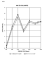
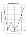
- FIGS. 3 to 5 are comparative graphs for explaining an effect of the system for recirculating engine exhaust gas according to the exemplary embodiment of the present disclosure, which illustrate authorized fuel efficiency, pressure waveform, and a fuel consumption rate, respectively.
- FIG. 3 illustrates a result of an air to fuel ratio (AFR) that is a criterion for performance in sucking fresh air, and more particularly, illustrates a result of comparing a Comparative Example in the related art and the present disclosure.
- AFR air to fuel ratio
- the same ratio of an amount of exhaust gas to be recirculated to an overall amount of exhaust gas that is, the same exhaust gas recirculation ratio is set to the Comparative Example and the present disclosure, and then the tests are performed.
- the system for recirculating exhaust gas according to the exemplary embodiment of the present disclosure has relatively excellent performance at a high engine speed rather than at a low engine speed.
- the present disclosure has a structure that is more simplified than a structure in the related art, but can achieve the same or better performance in sucking fresh air, and an improvement in engine performance can be expected.
- FIG. 4 illustrates a result of measuring a pressure waveform at an exhaust port.
- pressure is varied based on a displacement angle at which a crankshaft is rotated, and the number of cylinders, and the variation in pressure may be indicated as a pressure waveform as illustrated in FIG. 4 .
- Peaks and valleys are formed in the pressure waveform as many as the number of cylinders, and performance is better when a smooth waveform is formed at the peak portion.
- the Comparative Example has a sharp waveform having deep valleys in some sections, but the present disclosure has a smoother waveform, which has valleys that are not relatively deep, than the Comparative Example.
- the present disclosure has an exhaust pressure value that is generally greater than that of the Comparative Example, which means that the present disclosure may suck a larger amount of fresh air under the same fresh air suction condition, and it can be understood that performance in sucking fresh air is improved.
- the present disclosure has a structure that is more simplified than a structure in the related art, but can achieve the same or better performance in sucking fresh air, and an improvement in engine performance may be expected.
- FIG. 5 is a graph illustrating a fuel consumption rate.
- the present disclosure has a relatively low fuel consumption ratio in comparison with the Comparative Example, and as a result, it can be seen that the fuel efficiency of the present disclosure is better than that of the Comparative Example.
- the present disclosure has a structure that is more simplified than a structure in the related art, but can achieve the same or better fuel efficiency.
- the system for recirculating engine exhaust gas according to the exemplary embodiment of the present disclosure may remarkably reduce manufacturing costs by simplifying a structure of the system for recirculating exhaust gas.
- system for recirculating engine exhaust gas has a simplified structure, but may increase an amount of intake air, thereby improving output of the engine, and further improving fuel efficiency.
- the system for recirculating engine exhaust gas may be used to inhibit nitrogen oxide from being generated.
Landscapes
- Engineering & Computer Science (AREA)
- Chemical & Material Sciences (AREA)
- Combustion & Propulsion (AREA)
- Mechanical Engineering (AREA)
- General Engineering & Computer Science (AREA)
- Exhaust-Gas Circulating Devices (AREA)
- Output Control And Ontrol Of Special Type Engine (AREA)
- Supercharger (AREA)
Abstract
Description
- The present disclosure relates to a system for recirculating engine exhaust gas, and more particularly, to a system for recirculating engine exhaust gas, which mixes a part of exhaust gas discharged from an engine with air for combustion, and recirculates the mixture, thereby inhibiting nitrogen oxide (NOx) from being generated.
- In general, an engine uses gasoline or diesel as fuel, nitrogen oxide (NOx) is included in exhaust gas and discharged when fuel is combusted and exhaust gas is discharged.
- Because nitrogen oxide causes environmental pollution, a technology for inhibiting the nitrogen oxide from being generated is being developed, and as the technology, there is an exhaust gas recirculation (EGR) system.
- The exhaust gas recirculation system is known as a technology which reduces a concentration of oxygen by mixing a part of exhaust gas with air for combustion, and prevents a flame temperature from being rapidly raised, thereby inhibiting the nitrogen oxide from being generated.
- Meanwhile, a turbocharger may be installed in the engine. In the turbocharger, a turbine and a compressor are connected to each other by a single shaft, the turbine of the turbocharger is rotated by energy (temperature and pressure) of exhaust gas, and the compressor is driven by rotational force of the turbine. The compressed air is mixed with a larger amount of fuel, thereby improving efficiency of the engine.
- On the other hand, a pressure wave (or pressure pulse), which is propagated when an exhaust valve of a cylinder is opened, may act as back pressure for other cylinders. There is a problem in that the aforementioned back pressure interference action degrades performance of the exhaust gas recirculation system.
- In order to inhibit the exhaust gas interference, a twin-entry layout, which has two independent passages at a portion where exhaust gas flows into the turbine from an exhaust manifold, is known to be applied.
- In the exhaust gas recirculation system, when recirculating gas is obtained from only one exhaust manifold, imbalance in pressure and flow rate between two lines leading to the turbine is caused, which degrades overall performance of the turbine and the engine system.
- On the other hand, in a case in which the turbocharger, to which the twin-entry layout is applied, and the exhaust gas recirculation system are applied together, the recirculating gas is generally obtained from both the exhaust manifolds. However, in a case in which a phenomenon that exhaust pressures waves are exchanged through both the exhaust manifolds is not effectively inhibited, there is a problem in that back pressure is increased such that performance of the exhaust gas recirculation system deteriorates.
- On the other hand, there is an example in which the twin-entry layout is applied to the exhaust gas recirculation system, and recirculating gas is obtained from two recirculation lines. Valves are installed in the two recirculation lines, respectively, thereby inhibiting the back pressure exchange phenomenon. However, in this example, since additional valves need to be installed and designed, there is a problem in that costs are increased.
- There is another exhaust gas recirculation system for solving the aforementioned problem, and the exhaust gas recirculation system in the related art will be described with reference to the attached
FIG. 1 . - A plurality of cylinders is disposed in an
engine 10, and the cylinders may be designated as afirst cylinder group 12a and asecond cylinder group 12b. First andsecond exhaust manifolds first cylinder group 12a and thesecond cylinder group 12b, respectively. The first and second exhaust manifolds 21 and 22 are connected to aturbine 30 of a turbocharger. - That is, exhaust gas discharged from the first and
second cylinder groups turbine 30 through the first andsecond exhaust manifolds - The
turbine 30 is connected to acompressor 40, the turbine is driven by energy of exhaust gas, and driving power drives thecompressor 40 to compress air. - Meanwhile, a
first recirculation line 51 and asecond recirculation line 52 are connected to thefirst exhaust manifold 21 and thesecond exhaust manifold 22, respectively, such that a part of exhaust gas is obtained. - The other side of each of the first and
second recirculation lines pulse converter unit 60. Thepulse converter unit 60 serves to shut off a reverse flow and an exchange phenomenon of the exhaust pressure wave. - That is, exhaust gas, which circulates through the
first recirculation line 51, and exhaust gas, which circulates through thesecond recirculation line 52, are combined in thepulse converter unit 60. - A combining
recirculation line 70 is connected to thepulse converter unit 60, acooler 90 is connected to the other side of the combiningrecirculation line 70, and avalve 80 is provided on the combiningrecirculation line 70. Thevalve 80 inhibits a back pressure exchange phenomenon. The cooler 90 cools high-temperature exhaust gas. - The exhaust gas cooled by the cooler 90 is sent to a mixer where air and fuel are mixed.
- However, the exhaust gas recirculation system in the related art illustrated in
FIG. 1 has a complicated structure, and as a result, there is a problem in that manufacturing costs are increased. - In addition, in order to improve efficiency of the engine, it is necessary to additionally increase an amount of intake air, and it is necessary to further improve fuel efficiency.
- Therefore, a technical problem to be achieved in the present disclosure is to provide a system for recirculating engine exhaust gas which may have a simplified structure.
- In addition, another object of the present disclosure is to provide a system for recirculating engine exhaust gas, which improves output of an engine by increasing an amount of intake air, and further improves fuel efficiency.
- A technical problem to be achieved in the present disclosure is not limited to the aforementioned technical problem, and any other not-mentioned technical problem will be obviously understood from the description below by those skilled in the technical field to which the present disclosure pertains.
- In order to achieve the objects, a system for recirculating engine exhaust gas according to an exemplary embodiment of the present disclosure includes: first and second cylinder groups (12a, 12b) which include cylinders selected from cylinders of an engine; a first manifold (21) which is connected to the first cylinder group (12a), and combines and discharges exhaust gas discharged from the cylinders of the first cylinder group (12a); a second manifold (22) which is connected to the second cylinder group (12b), and combines and discharges exhaust gas discharged from the cylinders of the second cylinder group (12b); a branching unit (100) which is connected to the first manifold (21) and the second manifold (22), and at which exhaust gas discharged from both sides is combined; first and second exhaust lines (23, 24) which have one side that branches off from the branching unit (100), and the other side that is connected to a turbine (30) of a turbocharger as a pair, and provide a part of the exhaust gas to the turbine (30); and a combining recirculation line (70) which branches off from the branching unit (100).
- In addition, the system for recirculating engine exhaust gas according to the exemplary embodiment of the present disclosure may further include a valve (80) which is installed on the combining recirculation line (70), and inhibits a back pressure exchange phenomenon.
- In addition, the system for recirculating engine exhaust gas according to the exemplary embodiment of the present disclosure may further include a cooler (90) which is connected to the combining recirculation line (70), cools the exhaust gas flowing from the combining recirculation line (70), and supplies the cooled exhaust gas to a mixer of the engine.
- The branching unit (100) of the system for recirculating engine exhaust gas according to the exemplary embodiment of the present disclosure may communicate with the first manifold (21), the second manifold (22), and the combining recirculation line (70) at one point.
- Specific items of other exemplary embodiments are included in the detailed description and the drawings.
- The system for recirculating engine exhaust gas according to an exemplary embodiment of the present disclosure, which is configured as described above, may remarkably reduce manufacturing costs by simplifying a structure of the system for recirculating exhaust gas.
- In addition, the system for recirculating engine exhaust gas according to an exemplary embodiment of the present disclosure may increase an amount of intake air, thereby improving output of the engine, and further improving fuel efficiency.
-
-
FIG. 1 is a view for explaining a system for recirculating engine exhaust gas in the related art. -
FIG. 2 is a view for explaining a system for recirculating engine exhaust gas according to an exemplary embodiment of the present disclosure. -
FIGS. 3 to 5 are comparative graphs for explaining an effect of the system for recirculating engine exhaust gas according to the exemplary embodiment of the present disclosure, which illustrate authorized fuel efficiency, pressure waveform, and a fuel consumption rate, respectively. -
- 10: Engine
- 12a, 12b: First and second cylinder groups
- 21, 22: First and second exhaust manifolds
- 23, 24: First and second exhaust gas lines
- 30: Turbine
- 40: Compressor
- 51, 52: First and second recirculation lines
- 60: Pulse converter unit
- 70: Combining recirculation line
- 80: Valve
- 90: Cooler
- 100: Branching unit
- Advantages and features of the present disclosure and methods of achieving the advantages and features will be clear with reference to an exemplary embodiment described in detail below together with the accompanying drawings.
- Like reference numerals indicate like elements throughout the specification, constituent elements identical to constitute elements in the related art will be indicated by the same reference numerals, and duplicated descriptions thereof will be omitted.
- Meanwhile, the terms used in the description are defined considering the functions of the present disclosure and may vary depending on the intention or usual practice of a manufacturer. Therefore, the definitions should be made based on the entire contents of the present specification.
- Hereinafter, a system for recirculating engine exhaust gas according to an exemplary embodiment of the present disclosure will be described with reference to
FIG. 2 . - The attached
FIG. 2 is a view for explaining the system for recirculating engine exhaust gas according to the exemplary embodiment of the present disclosure. - The system for recirculating engine exhaust gas according to the exemplary embodiment of the present disclosure sends a part of the exhaust gas discharged from cylinders of an engine to a turbocharger, and cools the remaining part, and recirculates the remaining part.
- A plurality of cylinders is provided in the engine, and several cylinders selected from the plurality of cylinders are defined as first and
second cylinder groups - First and
second manifolds second cylinder groups - The
first manifold 21 is connected to thefirst cylinder group 12a, and combines and discharges exhaust gas discharged from the cylinders of thefirst cylinder group 12a. - In addition, the
second manifold 22 is connected to thesecond cylinder group 12b, and combines and discharges exhaust gas discharged from the cylinders of thesecond cylinder group 12b. - A branching
unit 100 is disposed between thefirst manifold 21 and thesecond manifold 22. - The exhaust gas discharged from the first and
second manifolds unit 100. - In addition, first and
second exhaust lines unit 100. The other side of each of the first andsecond exhaust lines turbine 30 of a turbocharger. - That is, the first and
second exhaust lines unit 100, to theturbine 30. - In addition, a combining
recirculation line 70 is connected to the branchingunit 100, such that a part of the combined exhaust gas branches off and is discharged. - When describing the branching
unit 100 in more detail, the branchingunit 100 may communicate with thefirst manifold 21, thesecond manifold 22, and the combiningrecirculation line 70 at one point. - In a case in which pressure in the
first manifold 21 is high, and pressure in thesecond manifold 22 is low, the high pressure in thefirst manifold 21 may act as back pressure to thesecond manifold 22, but with the aforementioned configuration, the combiningrecirculation line 70 communicates with the first andsecond manifolds - In addition, in the system for recirculating engine exhaust gas according to the exemplary embodiment of the present disclosure, a
valve 80 may be further installed on the combiningrecirculation line 70. Thevalve 80 inhibits a back pressure exchange phenomenon. - In addition, in the system for recirculating engine exhaust gas according to the exemplary embodiment of the present disclosure, a cooler 90 may be further installed on the combining
recirculation line 70. The cooler 90 cools the exhaust gas flowing from the combiningrecirculation line 70, and supplies the cooled exhaust gas to a mixer of the engine. - The system for recirculating engine exhaust gas (EGR system) according to the exemplary embodiment of the present disclosure, which is configured as described above, has a structure which is more simplified than a structure of an exhaust gas recirculation system in the related art, such that the system for recirculating engine exhaust gas may be easily manufactured, and manufacturing costs may be reduced.
- Meanwhile, since the
first manifold 21 joins thesecond manifold 22 at the branchingunit 100, there may be a risk that a back pressure interference phenomenon occurs, but the back pressure interference may be solved by adjusting thevalve 80. - In addition, a portion where back pressure is exchanged may be a communication point of the branching
unit 100, but because the exhaust gas to be recirculated is obtained at the communication point, the back pressure interference effect is reduced, and as a result, the exhaust gas recirculation system is stabilized. - In addition, in the system for recirculating exhaust gas according to the exemplary embodiment of the present disclosure, an amount of intake air is increased, and fuel efficiency is improved, and these effects will be described with reference to the attached
FIGS. 3 to 5 . - The attached
FIGS. 3 to 5 are comparative graphs for explaining an effect of the system for recirculating engine exhaust gas according to the exemplary embodiment of the present disclosure, which illustrate authorized fuel efficiency, pressure waveform, and a fuel consumption rate, respectively. -
FIG. 3 illustrates a result of an air to fuel ratio (AFR) that is a criterion for performance in sucking fresh air, and more particularly, illustrates a result of comparing a Comparative Example in the related art and the present disclosure. - Here, it can be understood that the higher the air to fuel ratio, the better the performance in sucking fresh air. The better performance in sucking fresh air advantageously acts upon the performance of an engine.
- In addition, the same ratio of an amount of exhaust gas to be recirculated to an overall amount of exhaust gas, that is, the same exhaust gas recirculation ratio is set to the Comparative Example and the present disclosure, and then the tests are performed.
- As can be seen from
FIG. 3 , it can be seen that the system for recirculating exhaust gas according to the exemplary embodiment of the present disclosure is better than the Comparative Example in terms of performance in sucking air, and this means that improved engine performance may be achieved in comparison with the related art. - In addition, it can be seen that the system for recirculating exhaust gas according to the exemplary embodiment of the present disclosure has relatively excellent performance at a high engine speed rather than at a low engine speed.
- In addition, it can be seen that performance in sucking fresh air similar to that of the Comparative Example is achieved even in the vicinity of a maximum torque point.
- That is, the present disclosure has a structure that is more simplified than a structure in the related art, but can achieve the same or better performance in sucking fresh air, and an improvement in engine performance can be expected.
-
FIG. 4 illustrates a result of measuring a pressure waveform at an exhaust port. - When the engine is driven, pressure is varied based on a displacement angle at which a crankshaft is rotated, and the number of cylinders, and the variation in pressure may be indicated as a pressure waveform as illustrated in
FIG. 4 . - Peaks and valleys are formed in the pressure waveform as many as the number of cylinders, and performance is better when a smooth waveform is formed at the peak portion.
- Referring to
FIG. 4 , when comparing the present disclosure with the Comparative Example, it can be seen that the Comparative Example has a sharp waveform having deep valleys in some sections, but the present disclosure has a smoother waveform, which has valleys that are not relatively deep, than the Comparative Example. - In addition, the present disclosure has an exhaust pressure value that is generally greater than that of the Comparative Example, which means that the present disclosure may suck a larger amount of fresh air under the same fresh air suction condition, and it can be understood that performance in sucking fresh air is improved.
- That is, the present disclosure has a structure that is more simplified than a structure in the related art, but can achieve the same or better performance in sucking fresh air, and an improvement in engine performance may be expected.
-
FIG. 5 is a graph illustrating a fuel consumption rate. - As illustrated in
FIG. 5 , the present disclosure has a relatively low fuel consumption ratio in comparison with the Comparative Example, and as a result, it can be seen that the fuel efficiency of the present disclosure is better than that of the Comparative Example. - That is, the present disclosure has a structure that is more simplified than a structure in the related art, but can achieve the same or better fuel efficiency.
- As described above, the system for recirculating engine exhaust gas according to the exemplary embodiment of the present disclosure may remarkably reduce manufacturing costs by simplifying a structure of the system for recirculating exhaust gas.
- In addition, the system for recirculating engine exhaust gas according to the exemplary embodiment of the present disclosure has a simplified structure, but may increase an amount of intake air, thereby improving output of the engine, and further improving fuel efficiency.
- It should be understood that the aforementioned exemplary embodiment is described for illustration in all aspects and are not limited, and the scope of the present disclosure shall be represented by the claims to be described below, and it should be construed that all of the changes or modified forms induced from the meaning and the scope of the claims, and an equivalent concept thereto are included in the scope of the present disclosure.
- The system for recirculating engine exhaust gas according to the exemplary embodiment of the present disclosure may be used to inhibit nitrogen oxide from being generated.
Claims (4)
- A system for recirculating engine exhaust gas, comprising:first and second cylinder groups (12a, 12b) which include cylinders selected from cylinders of an engine;a first manifold (21) which is connected to the first cylinder group (12a), and combines and discharges exhaust gas discharged from the cylinders of the first cylinder group (12a);a second manifold (22) which is connected to the second cylinder group (12b), and combines and discharges exhaust gas discharged from the cylinders of the second cylinder group (12b);a branching unit (100) which is connected to the first manifold (21) and the second manifold (22), and at which exhaust gas discharged from both sides is combined;first and second exhaust lines (23, 24) which have one side that branches off from the branching unit (100), and the other side that is connected to a turbine (30) of a turbocharger as a pair, and provide a part of the exhaust gas to the turbine (30); anda combining recirculation line (70) which branches off from the branching unit (100).
- The system of claim 1, further comprising:a valve (80) which is installed on the combining recirculation line (70), and inhibits a back pressure exchange phenomenon.
- The system of claim 2, further comprising:a cooler (90) which is connected to the combining recirculation line (70), cools the exhaust gas flowing from the combining recirculation line (70), and supplies the cooled exhaust gas to a mixer of the engine.
- The system of claim 1, wherein the branching unit (100) communicates with the first manifold (21), the second manifold (22), and the combining recirculation line (70) at one point.
Applications Claiming Priority (2)
| Application Number | Priority Date | Filing Date | Title |
|---|---|---|---|
| KR1020120035415A KR101992490B1 (en) | 2012-04-05 | 2012-04-05 | Exhaust Gas Recirculation of Engine |
| PCT/KR2013/002818 WO2013151356A1 (en) | 2012-04-05 | 2013-04-04 | System for recirculating engine exhaust gas |
Publications (2)
| Publication Number | Publication Date |
|---|---|
| EP2835524A1 true EP2835524A1 (en) | 2015-02-11 |
| EP2835524A4 EP2835524A4 (en) | 2016-04-13 |
Family
ID=49300772
Family Applications (1)
| Application Number | Title | Priority Date | Filing Date |
|---|---|---|---|
| EP13772086.8A Withdrawn EP2835524A4 (en) | 2012-04-05 | 2013-04-04 | System for recirculating engine exhaust gas |
Country Status (5)
| Country | Link |
|---|---|
| US (1) | US9506427B2 (en) |
| EP (1) | EP2835524A4 (en) |
| KR (1) | KR101992490B1 (en) |
| CN (1) | CN104204493A (en) |
| WO (1) | WO2013151356A1 (en) |
Cited By (1)
| Publication number | Priority date | Publication date | Assignee | Title |
|---|---|---|---|---|
| JP2017201144A (en) * | 2016-05-02 | 2017-11-09 | トヨタ自動車株式会社 | Internal combustion engine |
Families Citing this family (4)
| Publication number | Priority date | Publication date | Assignee | Title |
|---|---|---|---|---|
| JP6468241B2 (en) * | 2016-05-11 | 2019-02-13 | トヨタ自動車株式会社 | Control device for internal combustion engine |
| KR102437227B1 (en) | 2017-07-24 | 2022-08-29 | 현대두산인프라코어 주식회사 | Exhaust gas recirculation system for engine |
| CN108644036B (en) * | 2018-06-14 | 2020-10-02 | 河南柴油机重工有限责任公司 | Multi-channel exhaust gas connecting device of V-shaped EGR engine |
| JP7405065B2 (en) * | 2020-12-09 | 2023-12-26 | トヨタ自動車株式会社 | Internal combustion engine exhaust passage structure |
Family Cites Families (15)
| Publication number | Priority date | Publication date | Assignee | Title |
|---|---|---|---|---|
| SE517844C2 (en) * | 1997-12-03 | 2002-07-23 | Volvo Lastvagnar Ab | Combustion engine arrangement and procedure for reducing harmful emissions |
| JP2002052936A (en) * | 2000-08-10 | 2002-02-19 | Kasai Kogyo Co Ltd | Door inner seal mounting structure |
| EP1213468A3 (en) * | 2000-12-07 | 2003-11-26 | Caterpillar Inc. | Open manifold back pressure valve exhaust gas recirculation system |
| US6422217B1 (en) | 2000-12-19 | 2002-07-23 | Caterpillar Inc. | Back pressure valve drive EGR system |
| US6418721B1 (en) | 2001-01-05 | 2002-07-16 | Caterpillar Inc. | Two turbocharger exhaust gas re-circulation system having a first stage variable nozzle turbine |
| US6659090B2 (en) | 2002-01-10 | 2003-12-09 | Detroit Diesel Corporation | System for purging exhaust gases from exhaust gas recirculation system |
| US7287378B2 (en) * | 2002-10-21 | 2007-10-30 | International Engine Intellectual Property Company, Llc | Divided exhaust manifold system and method |
| KR101034288B1 (en) * | 2004-12-24 | 2011-05-16 | 현대자동차주식회사 | Engine exhaust gas recirculation system |
| DE102005008103A1 (en) * | 2005-02-21 | 2006-08-31 | Behr Gmbh & Co. Kg | Turbocharger engine |
| US7444815B2 (en) * | 2005-12-09 | 2008-11-04 | Deere & Company | EGR system for high EGR rates |
| US7363761B1 (en) * | 2006-10-31 | 2008-04-29 | International Engine Intellectual Property Company, Llc | Exhaust gas throttle for divided turbine housing turbocharger |
| JP2010084682A (en) * | 2008-10-01 | 2010-04-15 | Toyota Motor Corp | Exhaust circulating device for internal combustion engine |
| EP2295769A1 (en) * | 2009-08-14 | 2011-03-16 | International Engine Intellectual Property Company, LLC. | Exhaust system for engine braking |
| JP2011241723A (en) | 2010-05-17 | 2011-12-01 | Toyota Motor Corp | Egr device of internal combustion engine with supercharger |
| US8567189B2 (en) * | 2010-06-14 | 2013-10-29 | Ford Global Technologies, Llc | Twin scroll turbocharger with EGR takeoffs |
-
2012
- 2012-04-05 KR KR1020120035415A patent/KR101992490B1/en active Active
-
2013
- 2013-04-04 WO PCT/KR2013/002818 patent/WO2013151356A1/en not_active Ceased
- 2013-04-04 US US14/390,288 patent/US9506427B2/en not_active Expired - Fee Related
- 2013-04-04 EP EP13772086.8A patent/EP2835524A4/en not_active Withdrawn
- 2013-04-04 CN CN201380018489.9A patent/CN104204493A/en active Pending
Cited By (1)
| Publication number | Priority date | Publication date | Assignee | Title |
|---|---|---|---|---|
| JP2017201144A (en) * | 2016-05-02 | 2017-11-09 | トヨタ自動車株式会社 | Internal combustion engine |
Also Published As
| Publication number | Publication date |
|---|---|
| CN104204493A (en) | 2014-12-10 |
| US20150184619A1 (en) | 2015-07-02 |
| US9506427B2 (en) | 2016-11-29 |
| KR20130113098A (en) | 2013-10-15 |
| EP2835524A4 (en) | 2016-04-13 |
| KR101992490B1 (en) | 2019-06-24 |
| WO2013151356A1 (en) | 2013-10-10 |
Similar Documents
| Publication | Publication Date | Title |
|---|---|---|
| US10094337B2 (en) | Dual path cooled exhaust gas recirculation for turbocharged gasoline engines | |
| US8056340B2 (en) | EGR mixer for high-boost engine systems | |
| US9506427B2 (en) | System for recirculating engine exhaust gas | |
| US20060112940A1 (en) | Secondary internal combustion device for providing exhaust gas to EGR-equipped engine | |
| US20060174621A1 (en) | Two-turbocharger engine and method | |
| US20110036335A1 (en) | Hybrid intake system for superatmospheric charging of an engine intake manifold using lowpressure egr/fresh air blending | |
| JP2004308487A (en) | Exhaust supercharged engine with EGR | |
| JP5595107B2 (en) | Internal combustion engine | |
| US9255552B2 (en) | Engine system having dedicated donor cylinders for EGR | |
| KR102633863B1 (en) | Engine system and method of controlling the same | |
| US9062632B2 (en) | Internal combustion engine for a motor vehicle | |
| CN110234860B (en) | Method for controlling an internal combustion engine | |
| CN105508088A (en) | Waste gas recirculation system for spark ignition type supercharged engine and use method of waste gas recirculation system | |
| CN109356710B (en) | Successive supercharging system and control method | |
| US9726121B2 (en) | Engine system having reduced pressure EGR system | |
| CN106337728A (en) | Device and control strategy improving engine dynamic performance | |
| KR101683495B1 (en) | Engine system having turbo charger | |
| CN104088694A (en) | Internal combustion engine pressurizing system of turbochargers | |
| US11378027B2 (en) | Method for controlling an internal combustion engine | |
| CN214533326U (en) | Engine and vehicle | |
| Bernasconi et al. | Two-stage turbocharging solutions for tier 4 rail applications | |
| JP5983285B2 (en) | Turbocharged engine | |
| KR102463199B1 (en) | Engine system | |
| US10890129B1 (en) | High pressure loop exhaust gas recirculation and twin scroll turbocharger flow control | |
| RU2543925C1 (en) | Internal combustion engine |
Legal Events
| Date | Code | Title | Description |
|---|---|---|---|
| PUAI | Public reference made under article 153(3) epc to a published international application that has entered the european phase |
Free format text: ORIGINAL CODE: 0009012 |
|
| 17P | Request for examination filed |
Effective date: 20141013 |
|
| AK | Designated contracting states |
Kind code of ref document: A1 Designated state(s): AL AT BE BG CH CY CZ DE DK EE ES FI FR GB GR HR HU IE IS IT LI LT LU LV MC MK MT NL NO PL PT RO RS SE SI SK SM TR |
|
| AX | Request for extension of the european patent |
Extension state: BA ME |
|
| DAX | Request for extension of the european patent (deleted) | ||
| RA4 | Supplementary search report drawn up and despatched (corrected) |
Effective date: 20160310 |
|
| RIC1 | Information provided on ipc code assigned before grant |
Ipc: F02M 26/05 20160101ALN20160304BHEP Ipc: F02M 26/14 20160101AFI20160304BHEP Ipc: F02D 21/08 20060101ALI20160304BHEP Ipc: F01N 13/10 20100101ALI20160304BHEP Ipc: F02M 26/23 20160101ALN20160304BHEP Ipc: F02B 37/02 20060101ALI20160304BHEP Ipc: F02M 26/22 20160101ALI20160304BHEP Ipc: F02M 26/42 20160101ALI20160304BHEP |
|
| STAA | Information on the status of an ep patent application or granted ep patent |
Free format text: STATUS: EXAMINATION IS IN PROGRESS |
|
| 17Q | First examination report despatched |
Effective date: 20170221 |
|
| STAA | Information on the status of an ep patent application or granted ep patent |
Free format text: STATUS: THE APPLICATION IS DEEMED TO BE WITHDRAWN |
|
| 18D | Application deemed to be withdrawn |
Effective date: 20180529 |