EP2835514B1 - Système de refroidissement et procédé de fonctionnement correspondant - Google Patents
Système de refroidissement et procédé de fonctionnement correspondant Download PDFInfo
- Publication number
- EP2835514B1 EP2835514B1 EP14178848.9A EP14178848A EP2835514B1 EP 2835514 B1 EP2835514 B1 EP 2835514B1 EP 14178848 A EP14178848 A EP 14178848A EP 2835514 B1 EP2835514 B1 EP 2835514B1
- Authority
- EP
- European Patent Office
- Prior art keywords
- cooling
- low
- charge air
- temperature
- temperature coolant
- Prior art date
- Legal status (The legal status is an assumption and is not a legal conclusion. Google has not performed a legal analysis and makes no representation as to the accuracy of the status listed.)
- Not-in-force
Links
Images


Classifications
-
- F—MECHANICAL ENGINEERING; LIGHTING; HEATING; WEAPONS; BLASTING
- F02—COMBUSTION ENGINES; HOT-GAS OR COMBUSTION-PRODUCT ENGINE PLANTS
- F02B—INTERNAL-COMBUSTION PISTON ENGINES; COMBUSTION ENGINES IN GENERAL
- F02B29/00—Engines characterised by provision for charging or scavenging not provided for in groups F02B25/00, F02B27/00 or F02B33/00 - F02B39/00; Details thereof
- F02B29/04—Cooling of air intake supply
- F02B29/0406—Layout of the intake air cooling or coolant circuit
- F02B29/0437—Liquid cooled heat exchangers
- F02B29/0443—Layout of the coolant or refrigerant circuit
-
- B—PERFORMING OPERATIONS; TRANSPORTING
- B60—VEHICLES IN GENERAL
- B60H—ARRANGEMENTS OF HEATING, COOLING, VENTILATING OR OTHER AIR-TREATING DEVICES SPECIALLY ADAPTED FOR PASSENGER OR GOODS SPACES OF VEHICLES
- B60H1/00—Heating, cooling or ventilating [HVAC] devices
- B60H1/00271—HVAC devices specially adapted for particular vehicle parts or components and being connected to the vehicle HVAC unit
-
- B—PERFORMING OPERATIONS; TRANSPORTING
- B60—VEHICLES IN GENERAL
- B60H—ARRANGEMENTS OF HEATING, COOLING, VENTILATING OR OTHER AIR-TREATING DEVICES SPECIALLY ADAPTED FOR PASSENGER OR GOODS SPACES OF VEHICLES
- B60H1/00—Heating, cooling or ventilating [HVAC] devices
- B60H1/32—Cooling devices
- B60H1/3204—Cooling devices using compression
- B60H1/3228—Cooling devices using compression characterised by refrigerant circuit configurations
- B60H1/32281—Cooling devices using compression characterised by refrigerant circuit configurations comprising a single secondary circuit, e.g. at evaporator or condenser side
-
- F—MECHANICAL ENGINEERING; LIGHTING; HEATING; WEAPONS; BLASTING
- F01—MACHINES OR ENGINES IN GENERAL; ENGINE PLANTS IN GENERAL; STEAM ENGINES
- F01P—COOLING OF MACHINES OR ENGINES IN GENERAL; COOLING OF INTERNAL-COMBUSTION ENGINES
- F01P9/00—Cooling having pertinent characteristics not provided for in, or of interest apart from, groups F01P1/00 - F01P7/00
- F01P9/06—Cooling having pertinent characteristics not provided for in, or of interest apart from, groups F01P1/00 - F01P7/00 by use of refrigerating apparatus, e.g. of compressor or absorber type
-
- F—MECHANICAL ENGINEERING; LIGHTING; HEATING; WEAPONS; BLASTING
- F02—COMBUSTION ENGINES; HOT-GAS OR COMBUSTION-PRODUCT ENGINE PLANTS
- F02B—INTERNAL-COMBUSTION PISTON ENGINES; COMBUSTION ENGINES IN GENERAL
- F02B29/00—Engines characterised by provision for charging or scavenging not provided for in groups F02B25/00, F02B27/00 or F02B33/00 - F02B39/00; Details thereof
- F02B29/04—Cooling of air intake supply
- F02B29/0406—Layout of the intake air cooling or coolant circuit
- F02B29/0412—Multiple heat exchangers arranged in parallel or in series
-
- F—MECHANICAL ENGINEERING; LIGHTING; HEATING; WEAPONS; BLASTING
- F02—COMBUSTION ENGINES; HOT-GAS OR COMBUSTION-PRODUCT ENGINE PLANTS
- F02B—INTERNAL-COMBUSTION PISTON ENGINES; COMBUSTION ENGINES IN GENERAL
- F02B29/00—Engines characterised by provision for charging or scavenging not provided for in groups F02B25/00, F02B27/00 or F02B33/00 - F02B39/00; Details thereof
- F02B29/04—Cooling of air intake supply
- F02B29/045—Constructional details of the heat exchangers, e.g. pipes, plates, ribs, insulation, materials, or manufacturing and assembly
- F02B29/0462—Liquid cooled heat exchangers
-
- B—PERFORMING OPERATIONS; TRANSPORTING
- B60—VEHICLES IN GENERAL
- B60H—ARRANGEMENTS OF HEATING, COOLING, VENTILATING OR OTHER AIR-TREATING DEVICES SPECIALLY ADAPTED FOR PASSENGER OR GOODS SPACES OF VEHICLES
- B60H1/00—Heating, cooling or ventilating [HVAC] devices
- B60H1/00271—HVAC devices specially adapted for particular vehicle parts or components and being connected to the vehicle HVAC unit
- B60H2001/00307—Component temperature regulation using a liquid flow
-
- F—MECHANICAL ENGINEERING; LIGHTING; HEATING; WEAPONS; BLASTING
- F01—MACHINES OR ENGINES IN GENERAL; ENGINE PLANTS IN GENERAL; STEAM ENGINES
- F01P—COOLING OF MACHINES OR ENGINES IN GENERAL; COOLING OF INTERNAL-COMBUSTION ENGINES
- F01P11/00—Component parts, details, or accessories not provided for in, or of interest apart from, groups F01P1/00 - F01P9/00
- F01P11/14—Indicating devices; Other safety devices
- F01P2011/205—Indicating devices; Other safety devices using heat-accumulators
-
- F—MECHANICAL ENGINEERING; LIGHTING; HEATING; WEAPONS; BLASTING
- F01—MACHINES OR ENGINES IN GENERAL; ENGINE PLANTS IN GENERAL; STEAM ENGINES
- F01P—COOLING OF MACHINES OR ENGINES IN GENERAL; COOLING OF INTERNAL-COMBUSTION ENGINES
- F01P2060/00—Cooling circuits using auxiliaries
- F01P2060/02—Intercooler
-
- F—MECHANICAL ENGINEERING; LIGHTING; HEATING; WEAPONS; BLASTING
- F01—MACHINES OR ENGINES IN GENERAL; ENGINE PLANTS IN GENERAL; STEAM ENGINES
- F01P—COOLING OF MACHINES OR ENGINES IN GENERAL; COOLING OF INTERNAL-COMBUSTION ENGINES
- F01P3/00—Liquid cooling
- F01P3/22—Liquid cooling characterised by evaporation and condensation of coolant in closed cycles; characterised by the coolant reaching higher temperatures than normal atmospheric boiling-point
-
- Y—GENERAL TAGGING OF NEW TECHNOLOGICAL DEVELOPMENTS; GENERAL TAGGING OF CROSS-SECTIONAL TECHNOLOGIES SPANNING OVER SEVERAL SECTIONS OF THE IPC; TECHNICAL SUBJECTS COVERED BY FORMER USPC CROSS-REFERENCE ART COLLECTIONS [XRACs] AND DIGESTS
- Y02—TECHNOLOGIES OR APPLICATIONS FOR MITIGATION OR ADAPTATION AGAINST CLIMATE CHANGE
- Y02T—CLIMATE CHANGE MITIGATION TECHNOLOGIES RELATED TO TRANSPORTATION
- Y02T10/00—Road transport of goods or passengers
- Y02T10/10—Internal combustion engine [ICE] based vehicles
- Y02T10/12—Improving ICE efficiencies
Definitions
- the present invention relates to a cooling system for a supercharged internal combustion engine, preferably in a motor vehicle, having the features of the preamble of claim 1.
- the invention also relates to a method for operating such a cooling system.
- a supercharged internal combustion engine cooling system including a charge air cooling circuit and a refrigerant circuit
- the charge-air cooling circuit circulates a liquid low-temperature coolant.
- the charge air cooling circuit has a low-temperature charge air cooler for cooling the charge air and a low-temperature coolant radiator for cooling the low-temperature coolant.
- the refrigerant circuit circulates a refrigerant.
- the refrigerant circuit has an evaporator for evaporating the refrigerant and a condenser for condensing the refrigerant.
- the evaporator is fluidically coupled to the charge air cooling circuit, so that the heat required for evaporating the refrigerant is removed from the low-temperature coolant.
- the cooling capacity of the charge air cooling circuit can be improved.
- a similar cooling system is out of the US 6,006,540 known.
- the evaporator is arranged in a storage container for storing the low-temperature coolant, this reservoir in turn is arranged in a branch of the charge air cooling circuit, which is connected in parallel to a branch of the charge air cooling circuit containing the low-temperature coolant radiator.
- appropriate valve means can now the coolant flow in the charge air cooling circuit demand-dependent on the low-temperature coolant radiator and the Reservoir be divided.
- additional cooling power can be realized in the charge air cooling circuit by the coupling with the refrigerant circuit here.
- the charge ie pressure increase the charge air, which leads to an increase in performance of the internal combustion engine.
- the compression is inevitably accompanied by a temperature increase.
- the density of the air can be increased and thus increase the air mass flow, the combustion chambers of the internal combustion engine can be supplied.
- improved pollutant emission values can be achieved.
- cooling reduces the tendency to form nitrogen oxides.
- the charge air should thus be cooled only at full load, while it is supplied at partial load to the combustion chambers of the internal combustion engine quasi uncooled. For the part-load operation, this results in additional benefits. Since a lower air mass flows to the combustion chambers in the case of an uncooled charge air with a larger volume flow, a throttle valve of a fresh air system, which is used to control the air mass supplied to the combustion chambers, can be opened further so that overall the throttle losses on the fresh air side can be reduced.
- the problem here is that during operation of the internal combustion engine, especially when used in a motor vehicle, the various operating conditions, ie partial load and full load, very short-term succession can follow. For reasons of comfort, it is required that a transient state, which defines the transition from the partial load to the full load, is as short as possible.
- the internal combustion engine should react as promptly as possible to an increased power requirement.
- turbo lag can occur.
- a modern turbocharger thus takes less time than a conventional cooling system to be transferred from the part load to full load.
- the required high boost pressure is available in an acceptable time, the compressed and thereby heated charge air can not be cooled sufficiently quickly, so that the required performance of the internal combustion engine is not yet provided can be. This is only possible when the intercooler can develop its full performance.
- the present invention is concerned with the problem of providing for a cooling system of the type mentioned and for an associated operating method an improved embodiment, which is characterized in particular by the fact that in the shortest possible time of a state with reduced cooling of the charge air for a partial load operation of the internal combustion engine can be switched to a state with increased cooling of the charge air for a full load operation of the internal combustion engine.
- the invention is based on the general idea, the charge air cooling circuit and the refrigerant circuit not directly via the evaporator, but indirectly, namely via a coupling heat transfer to each other, on the one hand in a controlled or controllable with appropriate valve means, the evaporator immediate evaporator bypass of the refrigeration circuit and on the other hand, is arranged in a controlled or with appropriate valve means controllable coupling branch of the charge air cooling circuit.
- a fluidly separated, heat transfer coupling between the charge air cooling circuit and the refrigeration circuit is realized via the coupling heat exchanger.
- this construction is suitable for using a cooling circuit already present on the vehicle in addition to cooling the charge air.
- a cooling circuit already present on the vehicle in addition to cooling the charge air.
- today almost every motor vehicle is equipped with an air conditioning system for controlling the temperature of a passenger compartment, which comprises such a cooling circuit. Due to the controllability of the evaporator bypass, the coupling heat exchanger can simply switch on or off depending on demand. Likewise, any intermediate positions are possible, which include a partial turn on. In that regard, there is an improved transient behavior for the cooling system.
- the inventively proposed coupling branch for accommodating the coupling heat exchanger branches off via a branch point arranged upstream of the low-temperature charge air cooler from a flow of the charge air cooling circuit, which leads from the low-temperature coolant cooler to the low-temperature charge air cooler.
- the coupling heat exchanger Due to the controllability of the coupling branch, the coupling heat exchanger can also be switched on or switched off in a simple manner here. Likewise, basically any intermediate stages or power splits are also conceivable here.
- the accommodation of the coupling heat exchanger in the coupling branch also has the decisive advantage that the coupling heat exchanger can be decoupled from the charge air cooling circuit at partial load, so that it is not flowed through by the low-temperature coolant, while being cooled by means of the refrigerant circuit and kept at a correspondingly low temperature level can, for which it is flowed through by the refrigerant more or less.
- the thermal inertia of the coupling heat exchanger is taken out of the charge air cooling circuit, which significantly reduces the time required for the transient state.
- the entire cooling capacity of the coupling heat exchanger can be used for cooling the low-temperature coolant, which is then guided in total by the low-temperature charge air cooler, there to cool the charge air.
- the coupling branch contains a cryogenic intercooler for cooling the charge air and is returned via a return point, which is arranged in a leading from the low-temperature charge air cooler to the low-temperature coolant radiator return of the charge air cooling circuit.
- a cryogenic intercooler for cooling the charge air and is returned via a return point, which is arranged in a leading from the low-temperature charge air cooler to the low-temperature coolant radiator return of the charge air cooling circuit.
- at least two-stage cooling of the charge air is realized, namely on the one hand in the low-temperature intercooler and the other in the cryogenic intercooler.
- the low-temperature coolant cooled only by the low-temperature coolant radiator in the low-temperature charge air cooler while cooled by the low-temperature coolant radiator and the coupling heat exchanger low-temperature coolant in the cryogenic intercooler cools the charge air. This allows the charge air to cool particularly efficiently.
- the flow between the branch point and the low-temperature intercooler is controlled or controllably configured with corresponding valve means, whereby a quasi arbitrary distribution of the low-temperature coolant to the low-temperature charge air cooler and the cryogenic intercooler at full load is adjustable.
- the cryogenic charge air cooler may be arranged in the charge air path downstream of the low-temperature charge air cooler, so that the low-temperature charge air cooler causes a pre-cooling of the charge air, while the low-temperature charge air cooler causes a re-cooling of the charge air.
- a typical heat exchanger block consists of a plurality of parallel tubes, which can be traversed by the respective coolant and which have between them, which are traversed by the charge air and in which usually a plurality of fins and the like heat transfer structures are arranged. Some of these tubes may now define within the heat exchanger block a low temperature region that forms the low temperature charge air cooler while other tubes then define a low temperature region in the heat exchanger block forming the cryogenic intercooler.
- the coupling branch between the coupling heat exchanger and the cryogenic charge air cooler via a controlled or controllable by means of appropriate valve means connection with the flow can be fluidly connected.
- connection can now be blocked so that a part of the low-temperature coolant coming from the coupling heat exchanger then flows through the low-temperature charge air cooler, while a part of the low-temperature coolant passed by the coupling heat exchanger is fed to the low-temperature charge air cooler.
- a high-temperature refrigeration cycle may be provided in which a liquid high-temperature refrigerant circulates and which has a high-temperature charge air cooler for cooling the charge air and a high-temperature coolant cooler for cooling the high-temperature refrigerant.
- a liquid high-temperature refrigerant circulates and which has a high-temperature charge air cooler for cooling the charge air and a high-temperature coolant cooler for cooling the high-temperature refrigerant.
- the high-temperature charge air cooler is arranged in the charge air path upstream of the low-temperature charge air cooler.
- the high-temperature coolant is in the normal operating state of the internal combustion engine at a higher temperature level than the low-temperature coolant. Nevertheless, a pre-cooling of the charge air can be realized via the high-temperature intercooler, which improves the overall cooling capacity of the cooling system.
- According to an advantageous development can be provided to integrate the high-temperature charge air cooler and the low-temperature charge air cooler structurally in a common radiator block. This can be done particularly easily by a suitable assignment of the individual tubes to the low-temperature cooling circuit on the one hand and to the high-temperature cooling circuit on the other hand in a tube heat exchanger.
- a cryogenic intercooler it is also possible to realize a cooler block in which the three different coolers, namely high-temperature intercoolers, low-temperature intercoolers and low-temperature intercoolers, are integrally formed integrally.
- this can again be achieved particularly simply by assigning some of the tubes to the high-temperature intercooler, by associating a few other tubes with the low-temperature intercooler and by associating the remaining tubes with the cryogenic intercooler.
- the low-temperature intercooler may generally be preferably integrated into a charge air distributor, which separately supplies the charge air coming from the respective charging device, in particular via separate connecting lines, to the individual combustion chambers.
- a radiator block in which the low-temperature intercooler and / or the low-temperature intercooler and / or the high-temperature intercooler are integrated.
- the high-temperature cooling circuit can be, for example, an engine cooling circuit for cooling an engine block of the internal combustion engine.
- Such an engine cooling circuit is usually present in an internal combustion engine anyway, so that the cost of implementing the high-temperature charge air cooler is comparatively low.
- the high-temperature coolant radiator is exposed to a cooling air flow in the usual way.
- the high-temperature coolant cooler of the high-temperature cooling circuit or the engine cooling circuit can be expediently arranged in a cooling air path, and preferably downstream of the also arranged in this cooling air path low-temperature coolant radiator.
- the relative values "low temperature”, “low temperature” and “high temperature” refer to the charge air, so that the charge air in the high temperature cooler is cooled, but thereafter has a higher temperature than after the low temperature intercooler, while after the cryogenic Intercooler has a lower temperature than after the low temperature intercooler.
- a latent heat accumulator for cooling the low-temperature coolant may be integrated in the coupling heat exchanger.
- the latent heat storage in the coupling heat exchanger when changing from partial load to full load temporarily allows sufficient cooling of the low-temperature coolant.
- the evaporator may be arranged in a gas path, so that a gas stream passes through the evaporator, wherein in the evaporator, a latent heat storage medium or latent medium for cooling the gas stream flowing through the evaporator may be integrated.
- the refrigeration cycle may be an air conditioning circuit for cooling an air flow to be supplied to a passenger compartment of the vehicle so that an air path leading the air flow is passed through the evaporator.
- the refrigeration cycle is an existing in any modern vehicles climate cycle, which can be used in addition to cooling the charge air.
- the low-temperature coolant radiator can be arranged in a cooling air path, so that a cooling air flow is passed through the low-temperature coolant radiator, while the condenser is arranged upstream of the low-temperature coolant radiator in the cooling air path.
- the condenser is thus cooled directly by the cooling air flow.
- theoretically integration into a common heat exchanger module of the high-temperature coolant cooler and the low-temperature coolant cooler and optionally of the capacitor is conceivable.
- the low-temperature coolant radiator may be arranged again in a cooling air path, so that a cooling air flow is passed through the low-temperature coolant radiator.
- the capacitor for fluidly separated, heat transfer coupling the refrigerant circuit with the charge air cooling circuit upstream of the low-temperature coolant radiator can be integrated into the charge air cooling circuit.
- the capacitor is only indirectly with coupled to the cooling air flow, namely via the charge air cooling circuit.
- the space obtained by omitting the capacitor in the front end can then be filled by an enlarged low-temperature coolant radiator, so that in the vehicle, a low-temperature coolant circuit with increased power is available, which can be flexibly distributed depending on the application focus on the indirect re-cooling components. Due in part to complementary critical high-load scenarios of the condenser and low-temperature intercooler, the overall result is a more efficient cooling system in the sub-aspects.
- the method according to the invention is characterized in that the charge air cooling circuit is switchable at least between a first cooling power stage and a second cooling power stage depending on the cooling requirement of the charge air, wherein in the first cooling power stage the coupling heat exchanger does not depart from Low-temperature coolant is flowed through.
- the coupling heat exchanger In the first cooling power stage, the coupling heat exchanger is kept cooled or cooled by means of the refrigerant present in the refrigerant circuit.
- the low-temperature coolant radiator and the coupling heat exchanger are flowed through by the low-temperature coolant.
- the first cooling power stage realizes no or a relatively small cooling capacity and is assigned to the partial load.
- the second cooling power stage generates a relatively large cooling capacity and is assigned to the full load.
- the low-temperature coolant flows through the low-temperature charge air cooler.
- a low-temperature pump which drives the low-temperature coolant in the charge air cooling circuit, be reduced in terms of their capacity.
- the low temperature pump may be turned off for the first cooling power stage.
- a first partial flow of the low-temperature coolant, bypassing the coupling heat exchanger, can flow through the low-temperature charge air cooler, while a second partial flow of the low-temperature coolant flows through the coupling heat exchanger and then through the low-temperature charge air cooler.
- a total flow of the low-temperature coolant can bypass the coupling heat exchanger and flow through the low-temperature charge air cooler and the low-temperature charge air cooler in two partial flows in parallel.
- the temperatures of low temperature intercooler and low temperature intercooler are adjusted to achieve a pre-cooling of both the low temperature intercooler and the cryogenic intercooler. Again, this can be done with reduced flow of the low-temperature pump.
- additional cooling power can be provided by means of at least one latent heat accumulator for a switching operation from the first cooling power stage to the second cooling power stage become.
- a latent heat accumulator can be particularly easily designed so that it can extract sufficient heat from the low-temperature coolant for a predetermined, comparatively short time, for example for about 30 seconds, in order to provide the desired cooling performance for the transient state.
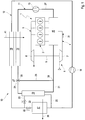
- Fig. 1 to 6 includes an internal combustion engine 1 in a conventional manner, an engine block 2 with a plurality of combustion chambers 3, which are formed by cylinders in which pistons are arranged adjustable in stroke.
- the internal combustion engine 1 is equipped to supply fresh air with a fresh air system 4, which supplies the combustion chambers 3 fresh air.
- the internal combustion engine 1 is equipped with an exhaust system 5.
- the internal combustion engine 1 is configured as a supercharged internal combustion engine 1 and therefore has a charging device 6, which is formed here by an exhaust gas turbocharger, which is also denoted by 6.
- the exhaust gas turbocharger 6 has a compressor 7, which is arranged in the fresh air system 4.
- the exhaust gas turbocharger 6 has a turbine 8, which is arranged in the exhaust system 5.
- the compressor 7 is drive-connected to the turbine 8 via a drive shaft 9.
- the internal combustion engine 1 is also equipped with a cooling system 10, which includes a charge air cooling circuit 11 and a refrigerant circuit 12.
- the charge air cooling circuit 11 includes a low-temperature pump 13, a low-temperature coolant radiator 14 and a low-temperature charge air cooler 15.
- a liquid low-temperature coolant which is for this purpose driven by the low-temperature pump 13.
- circulating in the refrigerant circuit 12 a phase-changing refrigerant.
- the refrigerant circuit 12 includes a compressor 16 for driving the refrigerant, an evaporator 17 for evaporating the refrigerant, and a condenser 18 for condensing the refrigerant.
- the cooling system 10 is also equipped with a coupling heat exchanger 19, which allows a fluidly separated heat transfer coupling between the charge air cooling circuit 11 and the refrigerant circuit 12.
- the coupling heat exchanger 19 is incorporated on the one hand in an evaporator bypass 20 of the refrigerant circuit 12, which bypasses the evaporator 17.
- the coupling heat exchanger 19 is incorporated in a coupling branch 21 of the charge air cooling circuit 11.
- the division of a refrigerant flow to the evaporator 17 and the coupling heat exchanger 19 is by means of suitable control valves 22, 23 controllable. As a result, at least the evaporator bypass 20 can be controlled or controlled.
- the coupling branch 21 can also be controlled, for example by means of a corresponding control valve 24.
- the coupling branch 21 is branched off via a branching point 25 from a supply line 26 of the charge air cooling circuit 11.
- the feed line 26 leads from the low-temperature coolant cooler 14 to the low-temperature charge air cooler 15.
- a return 27 of the charge air cooling circuit 11 leads from the low-temperature charge air cooler 15 to the low-temperature coolant cooler 14.
- the branch point 25 is thus arranged upstream of the low-temperature charge air cooler 15.
- the coupling branch 21 is recycled via an upstream of the low-temperature charge air cooler 15 and downstream of the branch point 25 arranged return point 28 in the flow 21 of the charge air cooling circuit 11.
- the return point 28 of the coupling branch 21 is arranged on the return 27, ie downstream of the low temperature charge air cooler 15.
- a cryogenic intercooler 29 is arranged in the coupling branch 21, which also serves to cool the charge air.
- the flow 26 between the branch point 25 and the low-temperature charge air cooler 15 may be controlled, for example by means of a corresponding control valve 30.
- the cryogenic intercooler 29 is disposed in a guided in the fresh air system 4 charge air path 31 downstream of the low-temperature charge air cooler 15.
- cryogenic charge air cooler 29 and low-temperature charge air cooler 15 are formed in a common heat exchanger block or cooler block 32. According to the Fig.
- Variants shown 33 may be provided, which the Coupling branch 21 between the coupling heat exchanger 19 and the cryogenic intercooler 29 fluidly connects to the flow 26.
- the connection 33 is controlled, for which purpose it can be equipped with a suitable control valve 34.
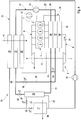
- the in the 4 to 6 Embodiments shown differ from those in the Fig. 1 to 3 shown embodiment by a high-temperature refrigerant circuit 35 in which circulates a liquid high-temperature refrigerant.
- the high temperature refrigeration cycle 35 includes a high temperature charge air cooler 36 for cooling the charge air and a high temperature coolant cooler 37 for cooling the high temperature refrigerant.
- the high-temperature cooling circuit 35 is an engine cooling circuit for cooling the engine block 2, wherein the interconnection shown here is selected purely by way of example.
- the engine cooling circuit will therefore also be referred to below as 35.
- the high-temperature charge air cooler 36 may be integrated into a separate branch of the engine cooling circuit 35.
- the high-temperature charge air cooler 36 is arranged in the charge air path 31 upstream of the low-temperature charge air cooler 15.
- the high-temperature charge air cooler 36 is structurally integrated into the cooler block 32 into which the low-temperature charge air cooler 15 and, if present, also the low-temperature charge air cooler 29 are formed.
- the engine cooling circuit 35 includes in the usual way a high-temperature pump 37 for driving the high-temperature coolant.
- the cooling circuit 12 is used for cooling an air flow 38.
- the air flow 38 can be supplied to a passenger compartment of the vehicle.
- the refrigeration circuit 12 is an air conditioning circuit, which will also be referred to below as 12 can.
- a latent heat accumulator 39 is integrated in the evaporator 17, with the aid of which the evaporator 17 by flowing air stream 38 can be cooled.
- a latent heat accumulator 40 is integrated, which serves for cooling the low-temperature coolant. It is clear that, in principle, in all the embodiments shown, such a latent heat accumulator 39 can be present in the evaporator 17 or a latent heat accumulator 40 in the coupling heat exchanger 19.
- the increased thermal inertia of the pitch circles caused by the latent medium can be structurally realized in a separate component.
- the low-temperature coolant radiator 14 is disposed in a cooling air path 41 such that a cooling air flow is passed through the low-temperature coolant radiator 14.
- the condenser 18 is arranged upstream of the low-temperature coolant radiator 14 in said cooling air flow or cooling air path 41.
- the high-temperature coolant cooler 37 may also be arranged in this cooling air path 41, but then expediently downstream of the low-temperature coolant cooler 14.
- the condenser 18 is integrated into the charge air cooling circuit 11 upstream of the low-temperature coolant radiator 14 so as to achieve a fluid-isolated heat transfer between the cooling circuit 12 and the charge air cooling circuit 11.
- the arrangement or configuration of the capacitor 18 according to Fig. 6 may be referred to as indirect capacitor 18 be while the arrangement or configuration of the capacitor 18 according to the Fig. 1 to 5 can be referred to as a direct capacitor 18.
- the indirect capacitor 18 is incorporated in the return 27 of the charge air cooling circuit 11.
- the cooling system presented here Fig. 1 to 6 can be operated as follows.
- the charge air cooling circuit 11 may be switchable at least between two different radiator output levels. Depending on the cooling requirement of the charge air, it is possible, for example, to switch between a first cooling power stage and a second cooling power stage.
- the second cooling power stage provides more cooling power than the first cooling power stage.
- the charge air may have a low cooling requirement when the internal combustion engine 1 is operated only in the lower load range, ie at partial load.
- a high cooling demand is present when the internal combustion engine 1 is operated in a higher and upper load range, ie at full load.
- the coupling heat exchanger 19 In the first cooling power stage, the coupling heat exchanger 19 is not flowed through by the low-temperature coolant, whereby it is fluidically decoupled from the rest of the charge air cooling circuit 11. At the same time, the coupling heat exchanger 19 is cooled during the first cooling power stage by means of the refrigeration circuit 12. In the second cooling power stage, the low-temperature coolant cooler 14 and the coupling heat exchanger 19 can now be flowed through by the low-temperature coolant. As a result, a lot of cooling power can be provided within a short time in order to cool the charge air quickly when changing from partial load to full load.
- the low-temperature coolant flows through the low-temperature charge air cooler 15, so that therefore the low-temperature pump 13 is in operation. It can the low-temperature pump 13 have a comparatively low or a reduced delivery rate. Likewise, it is basically possible to completely switch off the low-temperature pump 13 during the first cooling power stage.
- connection 33 allows for the first cooling power stage, a split of the coupling heat exchanger 19 total flow of the low-temperature coolant into two partial streams, which flow through the low-temperature charge air cooler 15 and the cryogenic intercooler 29 in parallel.
- additional cooling capacity in the in the Fig. 5 and 6 embodiments shown are provided by means of at least one latent heat accumulator 39 and 40, respectively.
Landscapes
- Engineering & Computer Science (AREA)
- Physics & Mathematics (AREA)
- Thermal Sciences (AREA)
- Mechanical Engineering (AREA)
- Chemical & Material Sciences (AREA)
- Combustion & Propulsion (AREA)
- General Engineering & Computer Science (AREA)
- Supercharger (AREA)
- Air-Conditioning For Vehicles (AREA)
Claims (13)
- Système de refroidissement pour un moteur à combustion interne (1) rechargé, de préférence dans un véhicule automobile,- comprenant un circuit de refroidissement d'air de suralimentation (11), dans lequel un liquide de refroidissement à basse température circule et qui présente un refroidisseur d'air de suralimentation à basse température (15) pour refroidir l'air de suralimentation et un refroidisseur de liquide de refroidissement à basse température (14) pour refroidir le liquide de refroidissement à basse température,- comprenant un circuit réfrigérant (12), dans lequel un liquide réfrigérant circule et qui présente un évaporateur (17) pour évaporer le liquide réfrigérant et un condensateur (18) pour condenser le liquide réfrigérant,- comprenant un échangeur de chaleur de couplage (19) pour coupler, de manière séparée sur le plan fluidique, avec une transmission de chaleur, le circuit de refroidissement d'air de suralimentation (11) au circuit réfrigérant (12), qui est disposé d'une part dans une dérivation d'évaporateur (20), contournant l'évaporateur (17), du circuit réfrigérant (12) et d'autre part dans un embranchement de couplage (21) du circuit de refroidissement d'air de suralimentation (11),- dans lequel l'embranchement de couplage (21) réalise un embranchement par l'intermédiaire d'un emplacement d'embranchement (25) depuis un conduit d'arrivée (26), menant du refroidisseur de liquide de refroidissement à basse température (14) vers le refroidisseur d'air de suralimentation à basse température (15), du circuit de refroidissement d'air de suralimentation (11),- dans lequel l'embranchement de couplage (21) contient un refroidisseur d'air de suralimentation à très basse température (29) pour refroidir l'air de suralimentation,
caractérisé en ce- que l'embranchement de couplage (21) est ramené par l'intermédiaire d'un emplacement de retour (28), qui est disposé dans un conduit de retour (27) menant d'un refroidisseur d'air de suralimentation à basse température (15) vers un refroidisseur de liquide de refroidissement à basse température (14), du circuit de refroidissement d'air de suralimentation (11). - Système de refroidissement selon la revendication 1,
caractérisé par un système d'assemblage (33), qui relie de manière fluidique l'embranchement de couplage (21) entre l'échangeur de chaleur de couplage (19) et le refroidisseur d'air de suralimentation à très basse température (29) au conduit d'arrivée (26). - Système de refroidissement selon la revendication 1 ou 2,
caractérisé par un circuit de refroidissement à haute température (35), dans lequel un liquide de refroidissement à haute température circule et qui présente un refroidisseur d'air de suralimentation à haute température (36) pour refroidir l'air de suralimentation et un refroidisseur de liquide de refroidissement à haute température (42) pour refroidir le liquide de refroidissement à haute température. - Système de refroidissement selon l'une quelconque des revendications 1 à 3, caractérisé en ce
qu'un accumulateur de chaleur latente (40) pour refroidir le liquide de refroidissement à basse température est intégré dans l'échangeur de chaleur de couplage (19). - Système de refroidissement selon l'une quelconque des revendications 1 à 4, caractérisé en ce- que l'évaporateur (17) est disposé dans un chemin de gaz de sorte qu'un flux de gaz (38) est guidé à travers l'évaporateur (17),- qu'un accumulateur de chaleur latente (39) pour refroidir le flux de gaz (38) s'écoulant à travers l'évaporateur (17) est intégré dans l'évaporateur (17).
- Système de refroidissement selon l'une quelconque des revendications 1 à 5, caractérisé en ce
que le circuit réfrigérant (12) est un circuit de climatisation pour refroidir un flux d'air (38) à amener à un espace de passager du véhicule de sorte qu'un chemin d'air guidant le flux d'air (38) est guidé à travers l'évaporateur (17). - Système de refroidissement selon l'une quelconque des revendications 1 à 6, caractérisé en ce- que le refroidisseur de liquide de refroidissement à basse température (14) est disposé dans un chemin d'air de refroidissement (41) de sorte qu'un flux d'air de refroidissement est guidé à travers le refroidisseur de liquide de refroidissement à basse température (14),- que le condensateur (18) est disposé dans le chemin d'air de refroidissement (41) en amont du refroidisseur de liquide de refroidissement à basse température (14).
- Système de refroidissement selon l'une quelconque des revendications 1 à 6, caractérisé en ce- que le refroidisseur de liquide de refroidissement à basse température (14) est disposé dans un chemin d'air de refroidissement (41) de sorte qu'un flux d'air de refroidissement est guidé à travers le refroidisseur de liquide de refroidissement à basse température (14),- que le condensateur (18) est incorporé dans le circuit de refroidissement d'air de suralimentation (11) afin de coupler, de manière séparée sur le plan fluidique, avec une transmission de chaleur, le circuit réfrigérant (12) au circuit de refroidissement d'air de suralimentation (11) en amont du refroidisseur de liquide de refroidissement à basse température (14).
- Procédé pour faire fonctionner un système de refroidissement (10) selon l'une quelconque des revendications 1 à 8,- où le circuit de refroidissement d'air de suralimentation (11) peut être commuté en fonction du besoin de refroidissement de l'air de suralimentation au moins entre un premier niveau de puissance de refroidissement et un deuxième niveau de puissance de refroidissement,- où l'échangeur de chaleur de couplage (19) n'est pas traversé par le liquide de refroidissement à basse température dans le premier niveau de puissance de refroidissement,- où l'échangeur de chaleur de couplage (19) est refroidi ou est maintenu froid à l'aide du circuit réfrigérant (11) dans le premier niveau de puissance de refroidissement,- où le refroidisseur de liquide de refroidissement à basse température (14) et l'échangeur de chaleur de couplage (19) sont traversés par le liquide de refroidissement à basse température dans le deuxième niveau de puissance de refroidissement.
- Procédé selon la revendication 9,
caractérisé en ce
que le liquide de refroidissement à basse température s'écoule à travers le refroidisseur d'air de suralimentation à basse pression (15) dans le premier niveau de puissance de refroidissement. - Procédé selon la revendication 9 ou 10,
caractérisé en ce
qu'un premier flux partiel du liquide de refroidissement à basse température s'écoule à travers le refroidisseur d'air de suralimentation à basse température (15) en contournant l'échangeur de chaleur de couplage (19) dans le deuxième niveau de puissance de refroidissement, tandis qu'un deuxième flux partiel du liquide de refroidissement à basse température s'écoule à travers l'échangeur de chaleur de couplage (19) puis à travers le refroidisseur d'air de suralimentation à température très basse (29). - Procédé selon l'une quelconque des revendications 9 à 11,
caractérisé en ce
qu'un flux global du liquide de refroidissement à basse température contourne l'échangeur de chaleur de couplage (19) dans le premier niveau de puissance de refroidissement et traverse en parallèle en deux flux partiels le refroidisseur d'air de suralimentation à basse température (15) et le refroidisseur d'air de suralimentation à très basse température (29). - Procédé selon l'une quelconque des revendications 9 à 12,
caractérisé en ce
qu'une puissance de refroidissement supplémentaire est fournie au moyen d'au moins un accumulateur de chaleur latente (39, 40) pour une opération de commutation pour commuter du premier niveau de puissance de refroidissement dans le deuxième niveau de puissance de refroidissement.
Applications Claiming Priority (1)
| Application Number | Priority Date | Filing Date | Title |
|---|---|---|---|
| DE201310215608 DE102013215608A1 (de) | 2013-08-07 | 2013-08-07 | Kühlsystem und zugehöriges Betriebsverfahren |
Publications (2)
| Publication Number | Publication Date |
|---|---|
| EP2835514A1 EP2835514A1 (fr) | 2015-02-11 |
| EP2835514B1 true EP2835514B1 (fr) | 2017-01-04 |
Family
ID=51225392
Family Applications (1)
| Application Number | Title | Priority Date | Filing Date |
|---|---|---|---|
| EP14178848.9A Not-in-force EP2835514B1 (fr) | 2013-08-07 | 2014-07-29 | Système de refroidissement et procédé de fonctionnement correspondant |
Country Status (3)
| Country | Link |
|---|---|
| US (1) | US9506395B2 (fr) |
| EP (1) | EP2835514B1 (fr) |
| DE (1) | DE102013215608A1 (fr) |
Families Citing this family (26)
| Publication number | Priority date | Publication date | Assignee | Title |
|---|---|---|---|---|
| GB2530509B (en) * | 2014-09-24 | 2016-11-02 | Ford Global Tech Llc | A motor vehicle having a charge air cooler |
| DE102014219954A1 (de) * | 2014-10-01 | 2016-04-07 | Mahle International Gmbh | Verfahren zum Betreiben einer Anordnung und Anordnung |
| DE102014219955A1 (de) * | 2014-10-01 | 2016-04-07 | Mahle International Gmbh | Verfahren zum Betreiben einer Anordnung und Anordnung |
| DE102014220097A1 (de) | 2014-10-02 | 2016-04-07 | Mahle International Gmbh | Kühlsystem und zugehöriges Betriebsverfahren |
| BR102014031677A2 (pt) * | 2014-12-17 | 2016-06-21 | Mahle Int Gmbh | sistema de admissão de um motor a combustão interna |
| FR3036744B1 (fr) * | 2015-05-29 | 2018-11-30 | Valeo Systemes Thermiques | Systeme de gestion thermique d'air d'admission d'un moteur thermique suralimente |
| DE102016006127B4 (de) | 2015-06-08 | 2022-12-29 | Modine Manufacturing Company | Ladeluftkühler und Verfahren |
| US9926836B2 (en) | 2015-07-02 | 2018-03-27 | General Electric Company | System and method for oxidant temperature control |
| DE102015120286A1 (de) * | 2015-11-24 | 2017-05-24 | Dr. Ing. H.C. F. Porsche Aktiengesellschaft | Kühlsystem in einem Fahrzeug und Verfahren zum Betrieb eines Kühlsystems |
| DE102015224593A1 (de) * | 2015-12-08 | 2017-06-08 | Mahle International Gmbh | Ladeluftkühlvorrichtung für eine Frischluftanlage einer Brennkraftmaschine eines Kraftfahrzeugs |
| US10202888B2 (en) * | 2015-12-08 | 2019-02-12 | Ford Global Technologies, Llc | Engine air path cooling system |
| WO2017114567A1 (fr) * | 2015-12-30 | 2017-07-06 | Wärtsilä Finland Oy | Procédé de nettoyage d'un refroidisseur d'air de suralimentation et moteur à combustion interne |
| MX2018009399A (es) | 2016-02-03 | 2019-01-10 | Modine Mfg Co | Intercambiador de calor de placas para refrigeración de baterias y conjunto de placas. |
| WO2017207038A1 (fr) * | 2016-05-31 | 2017-12-07 | Valeo Systemes Thermiques | Système de gestion thermique d'air d'admission d'un moteur thermique suralimenté |
| US10124647B2 (en) | 2016-09-27 | 2018-11-13 | Ford Global Technologies, Llc | Methods and systems for coolant system |
| US10690042B2 (en) | 2016-09-27 | 2020-06-23 | Ford Global Technologies, Llc | Methods and systems for coolant system |
| US10093147B2 (en) | 2016-09-27 | 2018-10-09 | Ford Global Technologies, Llc | Methods and systems for coolant system |
| US10570809B2 (en) * | 2016-09-27 | 2020-02-25 | Ford Global Technologies, Llc | Methods and systems for coolant system |
| US11002179B2 (en) | 2016-09-27 | 2021-05-11 | Ford Global Technologies, Llc | Methods and systems for control of coolant flow through an engine coolant system |
| DE102017122340A1 (de) | 2017-09-27 | 2019-03-28 | Ford Global Technologies, Llc | Verfahren und systeme für ein kühlmittelsystem |
| EP3499003B1 (fr) * | 2017-12-14 | 2020-05-06 | C.R.F. Società Consortile per Azioni | Système d'alimentation en air pour un moteur à combustion interne |
| CN108361098A (zh) * | 2018-03-22 | 2018-08-03 | 潍柴动力股份有限公司 | 两级增压中冷发动机的冷却系统 |
| FR3081034B1 (fr) * | 2018-05-14 | 2020-05-29 | Valeo Systemes Thermiques | Systeme de refroidissement d’un air d’admission de moteur a combustion interne |
| US10830122B2 (en) * | 2018-10-29 | 2020-11-10 | Fca Us Llc | Intake and charge air cooling system |
| US11878566B2 (en) | 2019-09-02 | 2024-01-23 | Nissan Motor Co., Ltd. | Heat exchange device for vehicles |
| US11680515B1 (en) | 2022-03-31 | 2023-06-20 | Fca Us Llc | Intake and charge air cooling system with passive variable charge enabler |
Family Cites Families (25)
| Publication number | Priority date | Publication date | Assignee | Title |
|---|---|---|---|---|
| FR1499898A (fr) * | 1966-03-02 | 1967-11-03 | Perfectionnements apportés aux dispositifs de refroidissement des moteurs à combustion interne suralimentés | |
| US4317439A (en) * | 1979-08-24 | 1982-03-02 | The Garrett Corporation | Cooling system |
| DE4104093A1 (de) * | 1991-02-11 | 1992-08-13 | Behr Gmbh & Co | Kuehlanlage fuer ein fahrzeug mit verbrennungsmotor |
| DE4114704C1 (fr) * | 1991-05-06 | 1992-02-20 | Mtu Friedrichshafen Gmbh | |
| US5408843A (en) * | 1994-03-24 | 1995-04-25 | Modine Manufacturing Co. | Vehicular cooling system and liquid cooled condenser therefor |
| DE19818649A1 (de) * | 1998-04-25 | 1999-10-28 | Behr Gmbh & Co | Fahrzeugklimaanlage und deren Verwendung |
| US6006540A (en) | 1998-08-03 | 1999-12-28 | Ford Global Technologies, Inc. | Charge air management system for automotive engine |
| DE19859129A1 (de) | 1998-12-21 | 2000-06-29 | Audi Ag | Einrichtung zur Kühlung der Ladeluft einer Brennkraftmaschine |
| DE10128877A1 (de) * | 2001-06-15 | 2002-12-19 | Behr Gmbh & Co | Fahrzeug-Kühlkreislauf für die Kühlung einer temperaturerhöhenden Einrichtung mittels eines Kühlmittels |
| DE10203772A1 (de) * | 2002-01-30 | 2004-04-15 | Robert Bosch Gmbh | Klimaanlage mit Heizfunktion und Verfahren zum Betrieb einer Klimaanlage mit Heizfunktion |
| DE10210132A1 (de) * | 2002-03-08 | 2003-09-18 | Behr Gmbh & Co | Kreislauf zur Kühlung von Ladeluft und Verfahren zum Betreiben eines derartigen Kreislaufs |
| DE10215262B4 (de) * | 2002-04-06 | 2014-12-31 | Daimler Ag | Kühlsystem, insbesondere für einen Kraftfahrzeugmotor mit indirekter Ladeluftkühlung |
| DE10333219A1 (de) * | 2003-07-22 | 2005-02-24 | Deere & Company, Moline | Kühlanordnung |
| DE10335567A1 (de) * | 2003-07-31 | 2005-03-10 | Behr Gmbh & Co Kg | Kreislaufanordnung zur Kühlung von Ladeluft und Verfahren zum Betreiben einer derartigen Kreislaufanordnung |
| EP1714014B1 (fr) * | 2003-12-19 | 2011-03-16 | Behr GmbH & Co. KG | Circuit pour refroidir l'air de suralimentation et procede pour faire fonctionner ledit circuit |
| EP1902877A1 (fr) * | 2006-09-20 | 2008-03-26 | Valeo Systèmes Thermiques | Procédé de gestion thermique, notamment pour le refroidissement moteur et/ou la climatisation d'un véhicule automobile et système de gestion thermique utilisant un tel procédé |
| DE102006044820B4 (de) * | 2006-09-20 | 2019-03-07 | MAN Truck & Bus Österreich AG | Kühlsystem einer Brennkraftmaschine mit Ladeluftzufuhr |
| DE102006048485A1 (de) * | 2006-10-11 | 2008-04-17 | Behr Gmbh & Co. Kg | Vorrichtung zur Ladeluftkühlung für einen Verbrennungsmotor, System mit einer Vorrichtung zur Ladeluftkühlung |
| DE102007004979A1 (de) * | 2007-02-01 | 2008-08-07 | Daimler Ag | Vorrichtung zur Kühlung einer Hybridfahrzeugbatterie |
| DE102007061495A1 (de) * | 2007-12-18 | 2009-06-25 | Volkswagen Ag | Explosionsverbrennungsmotor mit einer Kühleranordnung |
| SE532245C2 (sv) * | 2008-04-18 | 2009-11-24 | Scania Cv Ab | Kylarrangemang hos en överladdad förbränningsmotor |
| DE102008028290B4 (de) * | 2008-06-16 | 2019-05-16 | Mahle International Gmbh | Einrichtung zur Kühlung eines Kühlmittels, Kreislauf zur Aufladung einer Brennkraftmaschine und Verfahren zum Kühlen eines zur Aufladung einer Brennkraftmaschine vorgesehenen im Wesentlichen gasförmigen Ladefluids |
| DE102009051377A1 (de) * | 2009-10-30 | 2011-05-05 | Bayerische Motoren Werke Aktiengesellschaft | Antrieb für ein Hybridfahrzeug |
| DE102011116423A1 (de) * | 2011-10-19 | 2012-05-03 | Daimler Ag | Vorrichtung und Verfahren zur indirekten thermischen Kopplung zweier Kühlkreisläufe in einem Fahrzeug |
| DE102012209893B4 (de) * | 2012-06-13 | 2014-05-08 | Ford Global Technologies, Llc | Aufgeladene Brennkraftmaschine mit Ladeluftkühlung und Verfahren zum Betreiben einer derartigen Brennkraftmaschine |
-
2013
- 2013-08-07 DE DE201310215608 patent/DE102013215608A1/de not_active Withdrawn
-
2014
- 2014-07-29 EP EP14178848.9A patent/EP2835514B1/fr not_active Not-in-force
- 2014-08-06 US US14/453,071 patent/US9506395B2/en active Active
Non-Patent Citations (1)
| Title |
|---|
| None * |
Also Published As
| Publication number | Publication date |
|---|---|
| DE102013215608A1 (de) | 2015-02-12 |
| US9506395B2 (en) | 2016-11-29 |
| US20150040874A1 (en) | 2015-02-12 |
| EP2835514A1 (fr) | 2015-02-11 |
Similar Documents
| Publication | Publication Date | Title |
|---|---|---|
| EP2835514B1 (fr) | Système de refroidissement et procédé de fonctionnement correspondant | |
| DE102008028290B4 (de) | Einrichtung zur Kühlung eines Kühlmittels, Kreislauf zur Aufladung einer Brennkraftmaschine und Verfahren zum Kühlen eines zur Aufladung einer Brennkraftmaschine vorgesehenen im Wesentlichen gasförmigen Ladefluids | |
| DE102015220623B4 (de) | Wärmesystem für ein Elektro- oder Hybridfahrzeug | |
| EP1342893B1 (fr) | Dispositif de refroidissement de l'air suralimenté et procédé pour faire fonctionner un tel dispositif | |
| DE102012209893B4 (de) | Aufgeladene Brennkraftmaschine mit Ladeluftkühlung und Verfahren zum Betreiben einer derartigen Brennkraftmaschine | |
| DE102019109796A1 (de) | Wärmestrommanagementvorrichtung und Verfahren zum Betreiben einer Wärmestrommanagementvorrichtung | |
| EP2978948B1 (fr) | Module d'aspiration destiné à un moteur à combustion interne suralimenté | |
| EP3051114B1 (fr) | Moteur a combustion interne dote d'un refroidisseur de soupape de recyclage des gaz d'echappement | |
| DE10254016A1 (de) | Vorrichtung zur Kühlung von Ladeluft und Verfahren zum Betreiben einer derartigen Vorrichtung | |
| EP1342892B1 (fr) | Circuit pour refroidissement de l'air d'alimentation et méthode d'opération d'un tel circuit | |
| EP2423482B1 (fr) | Système de refroidissement pour un véhicule | |
| DE102014220097A1 (de) | Kühlsystem und zugehöriges Betriebsverfahren | |
| DE102015016241A1 (de) | Elektrisch angetriebenes Fahrzeug | |
| EP2020316A1 (fr) | Mémoire destinée au refroidissement d'un fluide essentiellement gazeux prévu pour le chargement du moteur | |
| DE102013021259A1 (de) | Aufladeeinrichtung für eine Verbrennungskraftmaschine eines Kraftwagens sowie Verfahren zum Betreiben einer solchen Aufladeeinrichtung | |
| EP3530899A1 (fr) | Système de refroidissement et moteur à combustion interne | |
| DE102014019097A1 (de) | Vorrichtung zur Ladeluftkühlung und Fahrzeug mit einer solchen Vorrichtung | |
| DE102007061495A1 (de) | Explosionsverbrennungsmotor mit einer Kühleranordnung | |
| DE102010015331A1 (de) | Kühleranordnung für ein Fahrzeug und Verfahen zum Betreiben einer Kühleranordnung | |
| EP2824300A1 (fr) | Unité d'entraînement pour un véhicule automobile | |
| DE102014219952A1 (de) | Aufgeladene Brennkraftmaschine sowie Fahrzeug | |
| EP1727976B1 (fr) | Moteur a combustion interne a dispositif d'humidification et echangeur thermique | |
| DE102020104888A1 (de) | Energiespeicher zum Speichern von elektrischer Energie für ein Kraftfahrzeug, insbesondere für einen Kraftwagen, sowie Kraftfahrzeug | |
| WO2020020998A1 (fr) | Moteur à combustion interne avec régulation de température d'air suralimentation au moyen d'un dispositif de sorption | |
| DE102018205393A1 (de) | Temperierungssystem für eine Batterie |
Legal Events
| Date | Code | Title | Description |
|---|---|---|---|
| PUAI | Public reference made under article 153(3) epc to a published international application that has entered the european phase |
Free format text: ORIGINAL CODE: 0009012 |
|
| 17P | Request for examination filed |
Effective date: 20140729 |
|
| AK | Designated contracting states |
Kind code of ref document: A1 Designated state(s): AL AT BE BG CH CY CZ DE DK EE ES FI FR GB GR HR HU IE IS IT LI LT LU LV MC MK MT NL NO PL PT RO RS SE SI SK SM TR |
|
| AX | Request for extension of the european patent |
Extension state: BA ME |
|
| RAP1 | Party data changed (applicant data changed or rights of an application transferred) |
Owner name: MAHLE BEHR GMBH & CO. KG Owner name: MAHLE INTERNATIONAL GMBH |
|
| R17P | Request for examination filed (corrected) |
Effective date: 20150715 |
|
| RBV | Designated contracting states (corrected) |
Designated state(s): AL AT BE BG CH CY CZ DE DK EE ES FI FR GB GR HR HU IE IS IT LI LT LU LV MC MK MT NL NO PL PT RO RS SE SI SK SM TR |
|
| GRAP | Despatch of communication of intention to grant a patent |
Free format text: ORIGINAL CODE: EPIDOSNIGR1 |
|
| RIC1 | Information provided on ipc code assigned before grant |
Ipc: F02B 29/04 20060101AFI20160307BHEP Ipc: F01P 9/06 20060101ALI20160307BHEP |
|
| INTG | Intention to grant announced |
Effective date: 20160404 |
|
| GRAJ | Information related to disapproval of communication of intention to grant by the applicant or resumption of examination proceedings by the epo deleted |
Free format text: ORIGINAL CODE: EPIDOSDIGR1 |
|
| INTC | Intention to grant announced (deleted) | ||
| GRAS | Grant fee paid |
Free format text: ORIGINAL CODE: EPIDOSNIGR3 |
|
| GRAP | Despatch of communication of intention to grant a patent |
Free format text: ORIGINAL CODE: EPIDOSNIGR1 |
|
| INTG | Intention to grant announced |
Effective date: 20160922 |
|
| GRAA | (expected) grant |
Free format text: ORIGINAL CODE: 0009210 |
|
| AK | Designated contracting states |
Kind code of ref document: B1 Designated state(s): AL AT BE BG CH CY CZ DE DK EE ES FI FR GB GR HR HU IE IS IT LI LT LU LV MC MK MT NL NO PL PT RO RS SE SI SK SM TR |
|
| REG | Reference to a national code |
Ref country code: GB Ref legal event code: FG4D Free format text: NOT ENGLISH |
|
| REG | Reference to a national code |
Ref country code: CH Ref legal event code: EP |
|
| REG | Reference to a national code |
Ref country code: AT Ref legal event code: REF Ref document number: 859460 Country of ref document: AT Kind code of ref document: T Effective date: 20170115 |
|
| REG | Reference to a national code |
Ref country code: IE Ref legal event code: FG4D Free format text: LANGUAGE OF EP DOCUMENT: GERMAN |
|
| REG | Reference to a national code |
Ref country code: DE Ref legal event code: R096 Ref document number: 502014002384 Country of ref document: DE |
|
| REG | Reference to a national code |
Ref country code: LT Ref legal event code: MG4D Ref country code: NL Ref legal event code: MP Effective date: 20170104 |
|
| PG25 | Lapsed in a contracting state [announced via postgrant information from national office to epo] |
Ref country code: NL Free format text: LAPSE BECAUSE OF FAILURE TO SUBMIT A TRANSLATION OF THE DESCRIPTION OR TO PAY THE FEE WITHIN THE PRESCRIBED TIME-LIMIT Effective date: 20170104 |
|
| REG | Reference to a national code |
Ref country code: FR Ref legal event code: PLFP Year of fee payment: 4 |
|
| PG25 | Lapsed in a contracting state [announced via postgrant information from national office to epo] |
Ref country code: IS Free format text: LAPSE BECAUSE OF FAILURE TO SUBMIT A TRANSLATION OF THE DESCRIPTION OR TO PAY THE FEE WITHIN THE PRESCRIBED TIME-LIMIT Effective date: 20170504 Ref country code: GR Free format text: LAPSE BECAUSE OF FAILURE TO SUBMIT A TRANSLATION OF THE DESCRIPTION OR TO PAY THE FEE WITHIN THE PRESCRIBED TIME-LIMIT Effective date: 20170405 Ref country code: NO Free format text: LAPSE BECAUSE OF FAILURE TO SUBMIT A TRANSLATION OF THE DESCRIPTION OR TO PAY THE FEE WITHIN THE PRESCRIBED TIME-LIMIT Effective date: 20170404 Ref country code: HR Free format text: LAPSE BECAUSE OF FAILURE TO SUBMIT A TRANSLATION OF THE DESCRIPTION OR TO PAY THE FEE WITHIN THE PRESCRIBED TIME-LIMIT Effective date: 20170104 Ref country code: LT Free format text: LAPSE BECAUSE OF FAILURE TO SUBMIT A TRANSLATION OF THE DESCRIPTION OR TO PAY THE FEE WITHIN THE PRESCRIBED TIME-LIMIT Effective date: 20170104 Ref country code: FI Free format text: LAPSE BECAUSE OF FAILURE TO SUBMIT A TRANSLATION OF THE DESCRIPTION OR TO PAY THE FEE WITHIN THE PRESCRIBED TIME-LIMIT Effective date: 20170104 |
|
| PG25 | Lapsed in a contracting state [announced via postgrant information from national office to epo] |
Ref country code: ES Free format text: LAPSE BECAUSE OF FAILURE TO SUBMIT A TRANSLATION OF THE DESCRIPTION OR TO PAY THE FEE WITHIN THE PRESCRIBED TIME-LIMIT Effective date: 20170104 Ref country code: BG Free format text: LAPSE BECAUSE OF FAILURE TO SUBMIT A TRANSLATION OF THE DESCRIPTION OR TO PAY THE FEE WITHIN THE PRESCRIBED TIME-LIMIT Effective date: 20170404 Ref country code: LV Free format text: LAPSE BECAUSE OF FAILURE TO SUBMIT A TRANSLATION OF THE DESCRIPTION OR TO PAY THE FEE WITHIN THE PRESCRIBED TIME-LIMIT Effective date: 20170104 Ref country code: PT Free format text: LAPSE BECAUSE OF FAILURE TO SUBMIT A TRANSLATION OF THE DESCRIPTION OR TO PAY THE FEE WITHIN THE PRESCRIBED TIME-LIMIT Effective date: 20170504 Ref country code: RS Free format text: LAPSE BECAUSE OF FAILURE TO SUBMIT A TRANSLATION OF THE DESCRIPTION OR TO PAY THE FEE WITHIN THE PRESCRIBED TIME-LIMIT Effective date: 20170104 Ref country code: PL Free format text: LAPSE BECAUSE OF FAILURE TO SUBMIT A TRANSLATION OF THE DESCRIPTION OR TO PAY THE FEE WITHIN THE PRESCRIBED TIME-LIMIT Effective date: 20170104 Ref country code: SE Free format text: LAPSE BECAUSE OF FAILURE TO SUBMIT A TRANSLATION OF THE DESCRIPTION OR TO PAY THE FEE WITHIN THE PRESCRIBED TIME-LIMIT Effective date: 20170104 |
|
| REG | Reference to a national code |
Ref country code: DE Ref legal event code: R097 Ref document number: 502014002384 Country of ref document: DE |
|
| PG25 | Lapsed in a contracting state [announced via postgrant information from national office to epo] |
Ref country code: EE Free format text: LAPSE BECAUSE OF FAILURE TO SUBMIT A TRANSLATION OF THE DESCRIPTION OR TO PAY THE FEE WITHIN THE PRESCRIBED TIME-LIMIT Effective date: 20170104 Ref country code: SK Free format text: LAPSE BECAUSE OF FAILURE TO SUBMIT A TRANSLATION OF THE DESCRIPTION OR TO PAY THE FEE WITHIN THE PRESCRIBED TIME-LIMIT Effective date: 20170104 Ref country code: CZ Free format text: LAPSE BECAUSE OF FAILURE TO SUBMIT A TRANSLATION OF THE DESCRIPTION OR TO PAY THE FEE WITHIN THE PRESCRIBED TIME-LIMIT Effective date: 20170104 Ref country code: RO Free format text: LAPSE BECAUSE OF FAILURE TO SUBMIT A TRANSLATION OF THE DESCRIPTION OR TO PAY THE FEE WITHIN THE PRESCRIBED TIME-LIMIT Effective date: 20170104 |
|
| PLBE | No opposition filed within time limit |
Free format text: ORIGINAL CODE: 0009261 |
|
| STAA | Information on the status of an ep patent application or granted ep patent |
Free format text: STATUS: NO OPPOSITION FILED WITHIN TIME LIMIT |
|
| PG25 | Lapsed in a contracting state [announced via postgrant information from national office to epo] |
Ref country code: DK Free format text: LAPSE BECAUSE OF FAILURE TO SUBMIT A TRANSLATION OF THE DESCRIPTION OR TO PAY THE FEE WITHIN THE PRESCRIBED TIME-LIMIT Effective date: 20170104 Ref country code: SM Free format text: LAPSE BECAUSE OF FAILURE TO SUBMIT A TRANSLATION OF THE DESCRIPTION OR TO PAY THE FEE WITHIN THE PRESCRIBED TIME-LIMIT Effective date: 20170104 |
|
| PG25 | Lapsed in a contracting state [announced via postgrant information from national office to epo] |
Ref country code: SI Free format text: LAPSE BECAUSE OF FAILURE TO SUBMIT A TRANSLATION OF THE DESCRIPTION OR TO PAY THE FEE WITHIN THE PRESCRIBED TIME-LIMIT Effective date: 20170104 |
|
| REG | Reference to a national code |
Ref country code: CH Ref legal event code: PL |
|
| PG25 | Lapsed in a contracting state [announced via postgrant information from national office to epo] |
Ref country code: CH Free format text: LAPSE BECAUSE OF NON-PAYMENT OF DUE FEES Effective date: 20170731 Ref country code: LI Free format text: LAPSE BECAUSE OF NON-PAYMENT OF DUE FEES Effective date: 20170731 |
|
| REG | Reference to a national code |
Ref country code: IE Ref legal event code: MM4A |
|
| REG | Reference to a national code |
Ref country code: BE Ref legal event code: MM Effective date: 20170731 |
|
| PG25 | Lapsed in a contracting state [announced via postgrant information from national office to epo] |
Ref country code: LU Free format text: LAPSE BECAUSE OF NON-PAYMENT OF DUE FEES Effective date: 20170729 |
|
| REG | Reference to a national code |
Ref country code: FR Ref legal event code: PLFP Year of fee payment: 5 |
|
| PG25 | Lapsed in a contracting state [announced via postgrant information from national office to epo] |
Ref country code: IE Free format text: LAPSE BECAUSE OF NON-PAYMENT OF DUE FEES Effective date: 20170729 |
|
| PG25 | Lapsed in a contracting state [announced via postgrant information from national office to epo] |
Ref country code: BE Free format text: LAPSE BECAUSE OF NON-PAYMENT OF DUE FEES Effective date: 20170731 |
|
| PG25 | Lapsed in a contracting state [announced via postgrant information from national office to epo] |
Ref country code: MT Free format text: LAPSE BECAUSE OF FAILURE TO SUBMIT A TRANSLATION OF THE DESCRIPTION OR TO PAY THE FEE WITHIN THE PRESCRIBED TIME-LIMIT Effective date: 20170104 |
|
| PGFP | Annual fee paid to national office [announced via postgrant information from national office to epo] |
Ref country code: FR Payment date: 20180726 Year of fee payment: 5 Ref country code: IT Payment date: 20180725 Year of fee payment: 5 |
|
| GBPC | Gb: european patent ceased through non-payment of renewal fee |
Effective date: 20180729 |
|
| PG25 | Lapsed in a contracting state [announced via postgrant information from national office to epo] |
Ref country code: GB Free format text: LAPSE BECAUSE OF NON-PAYMENT OF DUE FEES Effective date: 20180729 |
|
| PG25 | Lapsed in a contracting state [announced via postgrant information from national office to epo] |
Ref country code: HU Free format text: LAPSE BECAUSE OF FAILURE TO SUBMIT A TRANSLATION OF THE DESCRIPTION OR TO PAY THE FEE WITHIN THE PRESCRIBED TIME-LIMIT; INVALID AB INITIO Effective date: 20140729 Ref country code: MC Free format text: LAPSE BECAUSE OF FAILURE TO SUBMIT A TRANSLATION OF THE DESCRIPTION OR TO PAY THE FEE WITHIN THE PRESCRIBED TIME-LIMIT Effective date: 20170104 |
|
| PG25 | Lapsed in a contracting state [announced via postgrant information from national office to epo] |
Ref country code: CY Free format text: LAPSE BECAUSE OF FAILURE TO SUBMIT A TRANSLATION OF THE DESCRIPTION OR TO PAY THE FEE WITHIN THE PRESCRIBED TIME-LIMIT Effective date: 20170104 |
|
| PG25 | Lapsed in a contracting state [announced via postgrant information from national office to epo] |
Ref country code: MK Free format text: LAPSE BECAUSE OF FAILURE TO SUBMIT A TRANSLATION OF THE DESCRIPTION OR TO PAY THE FEE WITHIN THE PRESCRIBED TIME-LIMIT Effective date: 20170104 |
|
| PG25 | Lapsed in a contracting state [announced via postgrant information from national office to epo] |
Ref country code: TR Free format text: LAPSE BECAUSE OF FAILURE TO SUBMIT A TRANSLATION OF THE DESCRIPTION OR TO PAY THE FEE WITHIN THE PRESCRIBED TIME-LIMIT Effective date: 20170104 |
|
| PG25 | Lapsed in a contracting state [announced via postgrant information from national office to epo] |
Ref country code: FR Free format text: LAPSE BECAUSE OF NON-PAYMENT OF DUE FEES Effective date: 20190731 |
|
| PG25 | Lapsed in a contracting state [announced via postgrant information from national office to epo] |
Ref country code: AL Free format text: LAPSE BECAUSE OF FAILURE TO SUBMIT A TRANSLATION OF THE DESCRIPTION OR TO PAY THE FEE WITHIN THE PRESCRIBED TIME-LIMIT Effective date: 20170104 |
|
| PG25 | Lapsed in a contracting state [announced via postgrant information from national office to epo] |
Ref country code: IT Free format text: LAPSE BECAUSE OF NON-PAYMENT OF DUE FEES Effective date: 20190729 |
|
| REG | Reference to a national code |
Ref country code: AT Ref legal event code: MM01 Ref document number: 859460 Country of ref document: AT Kind code of ref document: T Effective date: 20190729 |
|
| PG25 | Lapsed in a contracting state [announced via postgrant information from national office to epo] |
Ref country code: AT Free format text: LAPSE BECAUSE OF NON-PAYMENT OF DUE FEES Effective date: 20190729 |
|
| PGFP | Annual fee paid to national office [announced via postgrant information from national office to epo] |
Ref country code: DE Payment date: 20210729 Year of fee payment: 8 |
|
| REG | Reference to a national code |
Ref country code: DE Ref legal event code: R119 Ref document number: 502014002384 Country of ref document: DE |
|
| PG25 | Lapsed in a contracting state [announced via postgrant information from national office to epo] |
Ref country code: DE Free format text: LAPSE BECAUSE OF NON-PAYMENT OF DUE FEES Effective date: 20230201 |