EP2835482B1 - Mehrgelenkige Scharnieranordnung mit Anschlag - Google Patents
Mehrgelenkige Scharnieranordnung mit Anschlag Download PDFInfo
- Publication number
- EP2835482B1 EP2835482B1 EP14180333.8A EP14180333A EP2835482B1 EP 2835482 B1 EP2835482 B1 EP 2835482B1 EP 14180333 A EP14180333 A EP 14180333A EP 2835482 B1 EP2835482 B1 EP 2835482B1
- Authority
- EP
- European Patent Office
- Prior art keywords
- track
- stop member
- slider
- hinge assembly
- relative
- Prior art date
- Legal status (The legal status is an assumption and is not a legal conclusion. Google has not performed a legal analysis and makes no representation as to the accuracy of the status listed.)
- Active
Links
Images



Classifications
-
- E—FIXED CONSTRUCTIONS
- E05—LOCKS; KEYS; WINDOW OR DOOR FITTINGS; SAFES
- E05D—HINGES OR SUSPENSION DEVICES FOR DOORS, WINDOWS OR WINGS
- E05D11/00—Additional features or accessories of hinges
- E05D11/06—Devices for limiting the opening movement of hinges
-
- E—FIXED CONSTRUCTIONS
- E05—LOCKS; KEYS; WINDOW OR DOOR FITTINGS; SAFES
- E05D—HINGES OR SUSPENSION DEVICES FOR DOORS, WINDOWS OR WINGS
- E05D15/00—Suspension arrangements for wings
- E05D15/40—Suspension arrangements for wings supported on arms movable in vertical planes
- E05D15/406—Suspension arrangements for wings supported on arms movable in vertical planes with pivoted arms and sliding guides
-
- E—FIXED CONSTRUCTIONS
- E05—LOCKS; KEYS; WINDOW OR DOOR FITTINGS; SAFES
- E05D—HINGES OR SUSPENSION DEVICES FOR DOORS, WINDOWS OR WINGS
- E05D15/00—Suspension arrangements for wings
- E05D15/28—Suspension arrangements for wings supported on arms movable in horizontal plane
- E05D15/30—Suspension arrangements for wings supported on arms movable in horizontal plane with pivoted arms and sliding guides
-
- E—FIXED CONSTRUCTIONS
- E05—LOCKS; KEYS; WINDOW OR DOOR FITTINGS; SAFES
- E05Y—INDEXING SCHEME ASSOCIATED WITH SUBCLASSES E05D AND E05F, RELATING TO CONSTRUCTION ELEMENTS, ELECTRIC CONTROL, POWER SUPPLY, POWER SIGNAL OR TRANSMISSION, USER INTERFACES, MOUNTING OR COUPLING, DETAILS, ACCESSORIES, AUXILIARY OPERATIONS NOT OTHERWISE PROVIDED FOR, APPLICATION THEREOF
- E05Y2600/00—Mounting or coupling arrangements for elements provided for in this subclass
- E05Y2600/10—Adjustable
-
- E—FIXED CONSTRUCTIONS
- E05—LOCKS; KEYS; WINDOW OR DOOR FITTINGS; SAFES
- E05Y—INDEXING SCHEME ASSOCIATED WITH SUBCLASSES E05D AND E05F, RELATING TO CONSTRUCTION ELEMENTS, ELECTRIC CONTROL, POWER SUPPLY, POWER SIGNAL OR TRANSMISSION, USER INTERFACES, MOUNTING OR COUPLING, DETAILS, ACCESSORIES, AUXILIARY OPERATIONS NOT OTHERWISE PROVIDED FOR, APPLICATION THEREOF
- E05Y2900/00—Application of doors, windows, wings or fittings thereof
- E05Y2900/10—Application of doors, windows, wings or fittings thereof for buildings or parts thereof
- E05Y2900/13—Type of wing
- E05Y2900/148—Windows
Definitions
- the present disclosure relates to a hinge assembly for a window, and more particularly, to a multi-bar linkage hinge assembly with a limit stop.
- Multi-bar linkage hinge assemblies may be employed in casement type or projection type window assemblies, for example. Such hinge assemblies may allow pivotal movement of a window vent or sash relative to a window frame.
- first and second hinge assemblies may be disposed on respective first and second vertically extending sides of the window sash.
- first and second hinge assemblies may be disposed on respective upper and lower horizontally extending sides of the window sash.
- GB 2 404 692 discloses a friction hinge which comprises a pivoting member coupled to a fixed channel member by an arrangement of stays.
- a restrictor blocking device is securable in one or more predetermined blocking positions in the channel member to enable users to predetermine variably the extent to which the window can be opened.
- the blocking device may be removably received in the channel.
- a locating abutment leg is provided at the proximal end of the pivoting member to assist correct positioning of the window sash relative to the pivoting member during installation
- GB 2 278 398 discloses a window support in the form of a friction stay.
- the window support includes an open-topped track to be fixed to a window frame, and a link arrangement for interconnecting the frame with the window sash.
- the link arrangement is pivotally mounted on sliders in the track, where movement of the slider is prevented during a substantial part of the movement of the friction stay.
- the track is closed by a profiled cap, while at the other end the track mounts an adjustable abutment, against which engages the slider during closing of the window.
- an angled end face of a link enters the cap.
- GB 2 498 598 discloses a stay comprising a track mountable on one of a window or frame and a link arrangement mounted on the other.
- the link arrangement includes a movable member that slides along the track as the window is pivoted relative to the frame.
- a stop arrangement has in-use and out of use conditions to prevent or allow the movable member to slide beyond a predetermined position respectively.
- the stop arrangement may include a sprung stop member located on the track and slidably movable between in-use and out of use conditions. The sprung stop member may automatically engage with a formation in the track when the moveable member reaches the predetermined position.
- GB 2 246 393 discloses a window restricting device slidably received in a channel of a hinge/stay system.
- the device comprises a body portion and means for releasably locking the body portion in a desired position in the channel.
- the device enables the opening of a window to be restricted, but on release of the device the window can be opened fully to facilitate cleaning and access therethrough.
- the device may be attached by a spacer to a slider of a stay-hinge linkage.
- the locking means suitably comprises a pivotable member with a pin for entering a hole in the channel.
- the present disclosure provides a hinge assembly for moving a window sash relative to a window frame.
- the hinge assembly comprises a track, a slider, a vent bar, a link and a stop member.
- the slider engages the track and is translatable along the track.
- the vent bar is pivotably coupled to the slider for rotation relative to the slider and movement with the slider relative to the track.
- the link includes a first end coupled to the track for rotation relative to the track about an axis and a second end coupled to the vent bar for rotation relative to the vent bar and the slider.
- the stop member engages the track and is configured to limit translational motion of the slider.
- the stop member is movable between a plurality of positions. Each of the plurality of positions corresponds to one of a plurality of ranges of translational motion of the slider.
- the stop member includes a first end disposed between the slider and a pin pivotably coupling the link to the track and a second end disposed on an opposite side of the pin from the first end.
- the pin extends through a slot formed in the stop member.
- a fastener may be received through an opening (e.g., an aperture or slot) in the stop member and may fix the stop member relative to the track.
- the opening may be disposed on the opposite side of the pin from the first end of the stop member.
- the track may include an opening that is aligned with the opening in the stop member and configured to receive the fastener.
- the opening may be a slot or an aperture, for example.
- the hinge assembly may include a brace pivotably coupled to the slider and the link.
- hinge assembly may include a connector pivotable coupled to the slider and the vent bar.
- the brace and the connector may be pivotable relative to the slider about a common axis.
- the axis about which the first end of the link pivots may be fixed relative to the track.
- the track may be configured to fixedly engage the window frame and the vent bar may be configured to fixedly engage the window sash.
- the stop member may be movable among an infinite number of positions between two opposing ends of a slot formed in the track or the stop member. Each of the positions may correspond to one of a plurality of ranges of linear motion of the second member.
- the track may include a plurality of first apertures and the stop member may include a plurality of second apertures that are selectively alignable with one or more of the first apertures to selectively fix the stop member at a selected one of a plurality of positions relative to the track Each of the positions may correspond to one of a plurality of ranges of linear motion of the second member.
- a window assembly 10 may include a window frame 12, a window vent or sash 14, and a pair of hinge assemblies 16 (shown schematically in Figure 1 ).
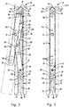
- the hinge assemblies 16 allow the window sash 14 to move relative to the window frame 12 between an open position ( Figures 1 and 2 ) and a closed position ( Figure 3 ).
- the window assembly 10 shown in Figure 1 is a projection type window assembly. Therefore, the hinge assemblies 16 may be disposed on sides of the window sash 14. However, it will be appreciated that the hinge assemblies 16 could be incorporated into other types of window assemblies, such as a casement type window assembly, for example.
- each of the hinge assemblies 16 may be a multi-bar linkage.
- the hinge assemblies 16 include a track 18, a slider 20, a link 22, a connector 24, a vent bar 26, a brace 28, and a stop member 30.
- the slider 20, link 22, connector 24, vent bar 26 and brace 28 are movable relative to the track 18 between an open position ( Figure 2 ) and a closed position ( Figure 3 ).
- the stop member 30 limits a range of motion of the slider 20 relative to the track 18, thereby limiting an angle to which the window sash 14 can be opened relative to the window frame 12 (i.e., limiting a range of motion of the window sash 14 relative to the window frame 12).
- the track 18 may include an elongated body 32 having parallel side flanges 34 extending therefrom.
- the body 32 and side flanges 34 may cooperate to form a channel 35 ( Figure 5 ) that receives the slider 20 and the stop member 30.
- the body 32 may include a plurality of apertures and/or slots 36 through which fasteners (not shown) may extend to fixedly secure the track 18 to the window frame 12.
- the track 18 may include a first end 38 and a second end 40.
- An end cap 42 may fixedly engage the first end 38 and may include a pair of camming surfaces 44 that the vent bar 26 may movably contact.
- a slot 46 may extend through the body 32 between an aperture 47 ( Figure 5 ) and the second end 40 of the track 18.
- the slider 20 slidably engages the track 18 and may include a body 48 and a pair of flanges 50 ( Figure 5 ) extending laterally outward from the body 48.
- the flanges 50 may fit between the body 32 and side flanges 34 of the track 18, thereby retaining the slider 20 in the channel 35 of the track 18.
- a side of the body 48 of the slider 20 that faces the body 32 of the track 18 may include a cavity formed therein.
- a friction adjuster pad (not shown) may be mounted within the cavity and may be adjustable therein to adjust an amount of sliding friction between the body 32 of the track 18 and the body 48 of the slider 20.
- a side 52 of the body 48 of the slider 20 that faces away from the track 18 may be flush with or raised slightly above the top surfaces 54 of the side flanges 34, as shown in Figure 6 .
- the slider 20 may be formed from brass, for example, so that the slider 20 smoothly and durably slides within the track 18. It will be appreciated, however, that the slider 20 could be formed from any other suitable metallic, polymeric or composite material, for example.
- the track 18, link 22, connector 24, vent bar 26 and brace 28 may be formed from steel, for example, or any other suitable metallic, polymeric or composite material.
- the link 22 may be a generally linear bar having a step 56 between first and second ends 58, 60.
- the first end 58 may be pivotably coupled to the track 18 and may include a first aperture 62.
- a first pivot pin 64 may engage the first aperture 62 and the aperture 47 ( Figure 5 ) in the track 18 and defines a first axis A1 ( Figure 4 ) about which the link 22 is rotatable relative to the track 18.
- the first axis A1 is fixed relative to the track 18 during motion of the hinge assembly 16 between the open and closed positions.
- a bearing washer and/or bushing 68 may receive the first pivot pin 64 between the link 22 and the track 18.
- the second end 60 of the link 22 is pivotably coupled to the vent bar 26.
- the second end 60 may include a second aperture 70 ( Figure 5 ) that receives a link second pivot pin 72 that defines a second axis A2 ( Figure 4 ) about which link 22 and the vent bar 26 are pivotable relative to each other.
- a third aperture 74 ( Figure 5 ) may be formed in the link 22 between the step 56 and the second end 60.
- the third aperture 74 may receive a third pivot pin 76 that defines a third axis A3 ( Figure 4 ) about which the link 22 and the brace 28 are pivotable relative to each other.
- the connector 24 may be a flat, linear bar having first and second ends 78, 80.
- the first and second ends 78, 80 may include first and second apertures 82, 84 ( Figure 5 ), respectively.
- the first aperture 82 may receive a fourth pivot pin 86 that defines a fourth axis A4 ( Figure 4 ) about which the connector 24 pivots relative to the slider 20 and about which the connector 24 and the brace 28 are pivotable relative to each other.
- the second aperture 84 may receive a fifth pivot pin 88 that defines a fifth axis A5 ( Figure 4 ) about which the connector 24 and the vent bar 26 are pivotable relative to each other.
- the vent bar 26 may include first and second ends 90, 92 and a step 94 disposed proximate the first end 90.
- the first end 90 may include a first aperture 96 ( Figure 5 ) that receives the fifth pivot pin 88 to allow for relative pivotable motion between the vent bar 26 and the connector 24.
- a second aperture 98 ( Figure 5 ) may be disposed between the step 94 and the second end 92 and may receive the second pivot pin 72 to allow for relative pivotable motion between the vent bar 26 and the link 22.
- the vent bar 26 may include a plurality of slots and/or apertures 100 disposed between the first and second ends 90, 92 that engage fasteners (not shown) for fixedly securing the window sash 14 to the vent bar 26.
- the first end 90 may include angled surfaces 101 that may slidably contact the camming surfaces 44 of the end cap 42. A tip of the first end 90 may be nested between the camming surfaces 44 when the hinge assembly 16 is in the closed position (as shown in Figure 3 ).
- the brace 28 may include first and second ends 102, 104 and a step 106 disposed between the first and second ends 102, 104.
- the first end 102 may include a first aperture 108 ( Figure 5 ) that receives the third pivot pin 76 to allow for relative pivotable motion between the brace 28 and the link 22.
- the second end 104 may include a second aperture 110 ( Figure 5 ) that receives the fourth pivot pin 86 to allow for relative pivotable motion between the brace 28 and the connector 24 and relative pivotable motion between the brace 28 and the slider 20.
- the hinge assembly 16 may not include the brace 28.
- the linkage of the hinge assembly 16 could be configured in a variety of different ways.
- the stop member 30 may be received in the channel 35 of the track 18 between the link 22 and the body 32 of the track 18.
- the stop member 30 may be adjustably fixed relative to the track 18 in a desired one of a plurality of positions.
- the stop member 30 may be a generally flat and linear bar including first and second ends 112, 114.
- An elongated slot 116 may extend through the stop member 30 between the first and second ends 112, 114.
- the first pivot pin 64 and the bushing 68 may extend through the slot 116.
- the first end 112 may be disposed between the slider 20 and the first pivot pin 64, and the second end 114 may be disposed on an opposite side of the first pivot pin 64 from the slider 20 and the first end 112 (i.e., the second end 114 may be disposed between the first pivot pin 64 and the second end 40 of the track 18).
- the first end 112 may include a raised portion 117 ( Figure 5 ). The slider 20 may abut the raised portion 117 in the open position.
- the stop member 30 may include an aperture 118 extending therethrough between the slot 116 and the second end 114.
- a fastener 120 ( Figure 2 ) may extend through the aperture 118 and the slot 46 in the track 18 and may engage the window frame 12 to fix the stop member 30 relative to the track 18.
- the stop member 30 Prior to tightening the fastener 120 against the stop member 30, the stop member 30 may be slid within the channel 35 of the track 18 to a desired one of a plurality of positions. Once the stop member 30 is moved to the desired position, the fastener 120 can be tightened against the stop member 30 to clamp the stop member 30 against the track 18.
- the stop member 30 could include a plurality of apertures 218 (as shown in Figure 7 ) and/or one or more slots disposed between the slot 116 and the second end 114 that may be selectively aligned with the slot 46 in the track 18 and/or one or more holes 246 (as shown in Figure 7 ) and/or slots formed in the track 18 between the first axis A1 and the second end 40 of the track 18.
- Such holes and/or slots could receive one or more fasteners that secure the stop member 30 relative to the track 18.
- the stop member 30 could include one or more slots or apertures disposed between the slot 116 and the first end 112 that could receive one or more fasteners for securing the stop member 30 relative to the track 18.
- the slider 20, link 22, connector 24, vent bar 26 and brace 28 may be movable relative to the track 18 between the open position ( Figure 2 ) and the closed position ( Figure 3 ) to move the window sash 14 between the open and closed positions.
- the body 48 of the slider 20 may abut the first end 112 of the stop member 30 when the hinge assembly 16 is in the open position. In this manner, the stop member 30 limits the range of translational motion of the slider 20, thereby limiting the range of motion of the link 22, connector 24, vent bar 26 and brace 28 and limiting the angle to which the window sash 14 can be opened relative to the window frame 12.
- the position of the stop member 30 relative to the track 18 will change the position of the slider 20 (and the positions of the link 22, connector 24, vent bar 26 and brace 28) in the open position.
- Fixing the stop member 30 in a position relatively close to the second end 40 of the track 18 e.g., as shown in Figure 4
- fixing the stop member in a position relatively farther from the second end 40 of the track 18 e.g., as shown in Figure 2
- the length of the slot 46 in the track 18 defines the range of positions at which the stop member 30 can be fixed relative to the track 18.
- aligning the aperture 118 with an end of the slot 46 closest to the first axis A1 will result in the least amount of travel of the slider 20 (and the least amount that the window sash 14 can be opened), and aligning the aperture 118 with an end of the slot 46 closest to the second end 40 of the track 18 will result in the greatest amount of travel of the slider 20 (and the greatest amount that the window sash 14 can be opened).
- the length of the slot 46 in the track 18 and/or the length of the slot 116 in the stop member 30 can be greater than or less than the lengths shown in the figures to provide a desired range of adjustability of the stop member 30 relative to the track 18.
- Providing the aperture 118, fastener 120 and slot 46 at a location between the first axis A1 and the second end 40 of the track 18 provides easier access to the fastener 120 after the hinge assembly 16 has been installed in the window assembly 10. This makes it easier for manufacturers, installers, and/or end users of the window assembly 10 to adjust the position of the stop member 30 (and hence, the angle to which the window sash 14 can be opened) after installation of the hinge assemblies 16 and/or after installation of the window assembly 10 in a house or building.
- the fastener 120 is disposed between the first axis A1 and the second end 40 of the track, the fastener 120 is still easily accessible, even when the window sash 14 is only open a small amount.
Landscapes
- Engineering & Computer Science (AREA)
- Mechanical Engineering (AREA)
- Hinges (AREA)
- Wing Frames And Configurations (AREA)
Claims (9)
- Scharnieranordnung (16) zum Bewegen eines Fensterflügels (14) relativ zu einem Fensterrahmen (12), die Scharnieranordnung (16) umfassend:eine Schiene (18);einen Schieber (20), der in die Schiene (18) eingreift und entlang der Schiene (18) verschiebbar ist;eine Entlüftungsstange (26), die schwenkbar mit dem Schieber (20) gekoppelt ist, um sich relativ zum Schieber (20) zu drehen und sich mit dem Schieber (20) relativ zur Schiene (18) zu bewegen;eine Verbindung (22) mit einem ersten Ende (58), das mit der Schiene (18) zur Drehung relativ zur Schiene (18) um eine Achse (A1) gekoppelt ist, und einem zweiten Ende (60), das mit der Entlüftungsstange (26) zur Drehung relativ zur Entlüftungsstange (26) und dem Schieber (20) gekoppelt ist; undein Anschlagelement (30), das in die Schiene (18) eingreift und konfiguriert ist, um die Parallelverschiebung des Schiebers (20) zu begrenzen, wobei das Anschlagelement (30) zwischen mehreren Positionen beweglich ist, wobei jede der mehreren Positionen einem aus mehreren Bereichen der Parallelverschiebung des Schiebers (20) entspricht; dadurch gekennzeichnet, dassdas Anschlagelement (30) ein erstes und ein zweites Ende (112, 114) beinhaltet, wobei das erste Ende (112) des Anschlagelements (30) zwischen dem Schieber (20) und einem Bolzen (64) angeordnet ist, der die Verbindung (22) schwenkbar mit der Schiene (18) verbindet, das zweite Ende (114) des Anschlagelements (30) auf einer gegenüberliegenden Seite des Bolzens (64) vom ersten Ende (112) angeordnet ist; undwobei sich der Stift (64) durch einen Schlitz (116) erstreckt, der in dem Anschlagelement (30) ausgebildet ist.
- Scharnieranordnung (16) nach Anspruch 1, wobei ein Befestigungselement (120) durch eine Öffnung (118) in dem Anschlagelement (30) aufgenommen wird und das Anschlagelement (30) in Bezug auf die Schiene (18) fixiert, wobei die Öffnung (118) auf der gegenüberliegenden Seite des Bolzens (64) vom ersten Ende (112) des Anschlagelements (30) angeordnet ist.
- Scharnieranordnung (16) nach Anspruch 2, wobei die Schiene (18) eine Öffnung (46) beinhaltet, die mit der Öffnung (118) in dem Anschlagelement (30) ausgerichtet und zur Aufnahme des Befestigungselements (120) konfiguriert ist.
- Scharnieranordnung (16) nach Anspruch 3, wobei die Öffnung (46) in der Schiene (30) ein Schlitz (46) ist.
- Scharnieranordnung (16) nach Anspruch 4, wobei das Anschlagelement (30) zwischen einer unbegrenzten Anzahl von Positionen zwischen zwei gegenüberliegenden Enden des Schlitzes (46, 118), die in der Schiene (18) oder dem Anschlagelement (30) ausgebildet sind, beweglich ist, wobei jede der Positionen einem aus mehreren Bereichen des Linearhubs des Schiebers (20) entspricht.
- Scharnieranordnung (16) nach einem der Ansprüche 4-5, wobei die Schiene (18) mehrere erste Öffnungen (246) beinhaltet und das Anschlagelement (30) mehrere zweite Öffnungen (218) beinhaltet, die selektiv mit einer oder mehreren der ersten Öffnungen (246) ausrichtbar sind, um das Anschlagelement (30) selektiv an einer ausgewählten aus mehreren Positionen relativ zur Schiene (18) zu befestigen, wobei jede der Positionen einem aus mehreren Bereichen des Linearhubs des Schiebers (20) entspricht.
- Scharnieranordnung (16) nach einem der Ansprüche 1-6, ferner umfassend eine Strebe (28), die schwenkbar mit dem Schieber (20) und der Verbindung (22) gekoppelt ist.
- Scharnieranordnung (16) nach Anspruch 7, ferner umfassend einen Verbinder (24), der schwenkbar mit dem Schieber (20) und der Entlüftungsstange (26) gekoppelt ist, wobei die Strebe (28) und der Verbinder (24) relativ zum Schieber (20) um eine gemeinsame Achse (A4) schwenkbar sind.
- Scharnieranordnung (16) nach einem der Ansprüche 1-8, wobei die Achse (A1) in Bezug auf die Schiene (18) fixiert ist.
Applications Claiming Priority (1)
| Application Number | Priority Date | Filing Date | Title |
|---|---|---|---|
| US201361863986P | 2013-08-09 | 2013-08-09 |
Publications (2)
| Publication Number | Publication Date |
|---|---|
| EP2835482A1 EP2835482A1 (de) | 2015-02-11 |
| EP2835482B1 true EP2835482B1 (de) | 2019-02-27 |
Family
ID=51292866
Family Applications (1)
| Application Number | Title | Priority Date | Filing Date |
|---|---|---|---|
| EP14180333.8A Active EP2835482B1 (de) | 2013-08-09 | 2014-08-08 | Mehrgelenkige Scharnieranordnung mit Anschlag |
Country Status (3)
| Country | Link |
|---|---|
| US (1) | US9303438B2 (de) |
| EP (1) | EP2835482B1 (de) |
| CA (1) | CA2858426C (de) |
Families Citing this family (2)
| Publication number | Priority date | Publication date | Assignee | Title |
|---|---|---|---|---|
| DE102017207707B3 (de) * | 2017-05-08 | 2018-06-28 | Roto Frank Ag | Beschlaganordnung sowie Fenster oder Tür mit einer derartigen Beschlaganordnung |
| US10765584B2 (en) * | 2019-01-03 | 2020-09-08 | Shanq-Ching Shieh | Foldable frame construction for mobility aids |
Family Cites Families (13)
| Publication number | Priority date | Publication date | Assignee | Title |
|---|---|---|---|---|
| EP0112681B1 (de) * | 1982-12-24 | 1986-09-24 | Securistyle Limited | Reibungsbeschläge |
| US4833754A (en) * | 1988-09-26 | 1989-05-30 | Yang Wu N | Supporting bracket for windows |
| GB9016524D0 (en) * | 1990-07-27 | 1990-09-12 | Securistyle Ltd | A window restricting device |
| US5093960A (en) * | 1991-06-27 | 1992-03-10 | Truth Division Of Spx Corporation | Window hinge hat |
| GB9311210D0 (en) * | 1993-05-29 | 1993-07-14 | Dgs Hardware Ltd | Improvements in or relating to window supports |
| US5711052A (en) * | 1996-11-04 | 1998-01-27 | Truth Hardware Corporation | Adjustable window hinge |
| US5898977A (en) * | 1997-09-25 | 1999-05-04 | Advantage Manufacturing Corp., Inc. | Non-handed in-line window supporting bracket |
| GB2363160B (en) * | 2000-06-05 | 2004-11-03 | Giovanni Maria Laporta | Friction hinge & window fitting |
| US20030046795A1 (en) * | 2001-09-13 | 2003-03-13 | Advantage Manufacturing Corp., Inc. | Reduced tolerance heavy duty window support bracket |
| US20030046794A1 (en) * | 2001-09-13 | 2003-03-13 | Malcolm Muir | Reduced tolerance window support bracket |
| US7024728B2 (en) * | 2002-02-11 | 2006-04-11 | Advantage Manufacturing Corp. | End cap for multi bar linkage hinge assembly |
| CN102232136B (zh) | 2010-04-26 | 2012-12-19 | 梁凯慈 | 多角度窗扇定位平开窗 |
| GB201121690D0 (en) * | 2011-12-16 | 2012-02-01 | Dgs Hardware Ltd | Restrictor stay for a window |
-
2014
- 2014-08-05 CA CA2858426A patent/CA2858426C/en active Active
- 2014-08-08 EP EP14180333.8A patent/EP2835482B1/de active Active
- 2014-08-08 US US14/454,788 patent/US9303438B2/en active Active
Non-Patent Citations (1)
| Title |
|---|
| None * |
Also Published As
| Publication number | Publication date |
|---|---|
| US9303438B2 (en) | 2016-04-05 |
| CA2858426A1 (en) | 2015-02-09 |
| EP2835482A1 (de) | 2015-02-11 |
| CA2858426C (en) | 2017-10-10 |
| US20150040351A1 (en) | 2015-02-12 |
Similar Documents
| Publication | Publication Date | Title |
|---|---|---|
| EP2140090B1 (de) | Begrenzungsvorrichtungen | |
| US7865999B2 (en) | Door motion controller assembly | |
| US20070289100A1 (en) | Casement Window Hinge | |
| US20120005964A1 (en) | Adjustable Glide Apparatus For A Sliding Panel Assembly | |
| EP2725175B1 (de) | Verstellbares Scharnier | |
| CA2615614A1 (en) | Friction hinge for push-out style window | |
| KR101968628B1 (ko) | 피봇 힌지 장치 | |
| CA2823357A1 (en) | Adjustable pocket door frame | |
| CN111779393A (zh) | 门系统 | |
| EP3458666B1 (de) | System zur drehbaren kupplung eines verschlusselements und stationäre trägerstruktur | |
| US11542738B2 (en) | Door closers | |
| NZ286247A (en) | Window stay comprises a sliding means moves along a stay and is lockable in set positions | |
| EP3604723B1 (de) | Kombination eines profils und eines scharniers für ein fenster oder eine tür mit zubehör zur anpassung der position zwischen dem scharnier und dem profil des fensters oder der tür | |
| CA2858426C (en) | Multi-bar linkage hinge assembly with limit stop | |
| EP3580419B1 (de) | Türschliesser | |
| CA1199349A (en) | Device for automatically closing door | |
| GB2366323A (en) | Friction stay with biassed slider | |
| GB2558525A (en) | Hinge assembly | |
| GB2284014A (en) | Window friction stay | |
| US12398587B1 (en) | Window hinge assembly and methods | |
| CN119855971A (zh) | 收纳门悬挂系统的改进 | |
| CA2566176A1 (en) | Hinge assembly for casement windows | |
| GB2267932A (en) | Friction stay with spacer | |
| NL2014770B1 (en) | Security device for a window. | |
| AU2014202554A1 (en) | Door Assembly |
Legal Events
| Date | Code | Title | Description |
|---|---|---|---|
| PUAI | Public reference made under article 153(3) epc to a published international application that has entered the european phase |
Free format text: ORIGINAL CODE: 0009012 |
|
| 17P | Request for examination filed |
Effective date: 20140808 |
|
| AK | Designated contracting states |
Kind code of ref document: A1 Designated state(s): AL AT BE BG CH CY CZ DE DK EE ES FI FR GB GR HR HU IE IS IT LI LT LU LV MC MK MT NL NO PL PT RO RS SE SI SK SM TR |
|
| AX | Request for extension of the european patent |
Extension state: BA ME |
|
| R17P | Request for examination filed (corrected) |
Effective date: 20150811 |
|
| RBV | Designated contracting states (corrected) |
Designated state(s): AL AT BE BG CH CY CZ DE DK EE ES FI FR GB GR HR HU IE IS IT LI LT LU LV MC MK MT NL NO PL PT RO RS SE SI SK SM TR |
|
| STAA | Information on the status of an ep patent application or granted ep patent |
Free format text: STATUS: EXAMINATION IS IN PROGRESS |
|
| 17Q | First examination report despatched |
Effective date: 20161222 |
|
| GRAP | Despatch of communication of intention to grant a patent |
Free format text: ORIGINAL CODE: EPIDOSNIGR1 |
|
| STAA | Information on the status of an ep patent application or granted ep patent |
Free format text: STATUS: GRANT OF PATENT IS INTENDED |
|
| INTG | Intention to grant announced |
Effective date: 20180906 |
|
| GRAS | Grant fee paid |
Free format text: ORIGINAL CODE: EPIDOSNIGR3 |
|
| GRAA | (expected) grant |
Free format text: ORIGINAL CODE: 0009210 |
|
| STAA | Information on the status of an ep patent application or granted ep patent |
Free format text: STATUS: THE PATENT HAS BEEN GRANTED |
|
| AK | Designated contracting states |
Kind code of ref document: B1 Designated state(s): AL AT BE BG CH CY CZ DE DK EE ES FI FR GB GR HR HU IE IS IT LI LT LU LV MC MK MT NL NO PL PT RO RS SE SI SK SM TR |
|
| REG | Reference to a national code |
Ref country code: GB Ref legal event code: FG4D |
|
| REG | Reference to a national code |
Ref country code: CH Ref legal event code: EP |
|
| REG | Reference to a national code |
Ref country code: AT Ref legal event code: REF Ref document number: 1101584 Country of ref document: AT Kind code of ref document: T Effective date: 20190315 |
|
| REG | Reference to a national code |
Ref country code: IE Ref legal event code: FG4D |
|
| REG | Reference to a national code |
Ref country code: DE Ref legal event code: R096 Ref document number: 602014041689 Country of ref document: DE |
|
| REG | Reference to a national code |
Ref country code: NL Ref legal event code: MP Effective date: 20190227 |
|
| REG | Reference to a national code |
Ref country code: LT Ref legal event code: MG4D |
|
| PG25 | Lapsed in a contracting state [announced via postgrant information from national office to epo] |
Ref country code: PT Free format text: LAPSE BECAUSE OF FAILURE TO SUBMIT A TRANSLATION OF THE DESCRIPTION OR TO PAY THE FEE WITHIN THE PRESCRIBED TIME-LIMIT Effective date: 20190627 Ref country code: SE Free format text: LAPSE BECAUSE OF FAILURE TO SUBMIT A TRANSLATION OF THE DESCRIPTION OR TO PAY THE FEE WITHIN THE PRESCRIBED TIME-LIMIT Effective date: 20190227 Ref country code: FI Free format text: LAPSE BECAUSE OF FAILURE TO SUBMIT A TRANSLATION OF THE DESCRIPTION OR TO PAY THE FEE WITHIN THE PRESCRIBED TIME-LIMIT Effective date: 20190227 Ref country code: NO Free format text: LAPSE BECAUSE OF FAILURE TO SUBMIT A TRANSLATION OF THE DESCRIPTION OR TO PAY THE FEE WITHIN THE PRESCRIBED TIME-LIMIT Effective date: 20190527 Ref country code: NL Free format text: LAPSE BECAUSE OF FAILURE TO SUBMIT A TRANSLATION OF THE DESCRIPTION OR TO PAY THE FEE WITHIN THE PRESCRIBED TIME-LIMIT Effective date: 20190227 Ref country code: LT Free format text: LAPSE BECAUSE OF FAILURE TO SUBMIT A TRANSLATION OF THE DESCRIPTION OR TO PAY THE FEE WITHIN THE PRESCRIBED TIME-LIMIT Effective date: 20190227 |
|
| PG25 | Lapsed in a contracting state [announced via postgrant information from national office to epo] |
Ref country code: GR Free format text: LAPSE BECAUSE OF FAILURE TO SUBMIT A TRANSLATION OF THE DESCRIPTION OR TO PAY THE FEE WITHIN THE PRESCRIBED TIME-LIMIT Effective date: 20190528 Ref country code: IS Free format text: LAPSE BECAUSE OF FAILURE TO SUBMIT A TRANSLATION OF THE DESCRIPTION OR TO PAY THE FEE WITHIN THE PRESCRIBED TIME-LIMIT Effective date: 20190627 Ref country code: HR Free format text: LAPSE BECAUSE OF FAILURE TO SUBMIT A TRANSLATION OF THE DESCRIPTION OR TO PAY THE FEE WITHIN THE PRESCRIBED TIME-LIMIT Effective date: 20190227 Ref country code: LV Free format text: LAPSE BECAUSE OF FAILURE TO SUBMIT A TRANSLATION OF THE DESCRIPTION OR TO PAY THE FEE WITHIN THE PRESCRIBED TIME-LIMIT Effective date: 20190227 Ref country code: BG Free format text: LAPSE BECAUSE OF FAILURE TO SUBMIT A TRANSLATION OF THE DESCRIPTION OR TO PAY THE FEE WITHIN THE PRESCRIBED TIME-LIMIT Effective date: 20190527 Ref country code: RS Free format text: LAPSE BECAUSE OF FAILURE TO SUBMIT A TRANSLATION OF THE DESCRIPTION OR TO PAY THE FEE WITHIN THE PRESCRIBED TIME-LIMIT Effective date: 20190227 |
|
| REG | Reference to a national code |
Ref country code: AT Ref legal event code: MK05 Ref document number: 1101584 Country of ref document: AT Kind code of ref document: T Effective date: 20190227 |
|
| PG25 | Lapsed in a contracting state [announced via postgrant information from national office to epo] |
Ref country code: SK Free format text: LAPSE BECAUSE OF FAILURE TO SUBMIT A TRANSLATION OF THE DESCRIPTION OR TO PAY THE FEE WITHIN THE PRESCRIBED TIME-LIMIT Effective date: 20190227 Ref country code: IT Free format text: LAPSE BECAUSE OF FAILURE TO SUBMIT A TRANSLATION OF THE DESCRIPTION OR TO PAY THE FEE WITHIN THE PRESCRIBED TIME-LIMIT Effective date: 20190227 Ref country code: RO Free format text: LAPSE BECAUSE OF FAILURE TO SUBMIT A TRANSLATION OF THE DESCRIPTION OR TO PAY THE FEE WITHIN THE PRESCRIBED TIME-LIMIT Effective date: 20190227 Ref country code: CZ Free format text: LAPSE BECAUSE OF FAILURE TO SUBMIT A TRANSLATION OF THE DESCRIPTION OR TO PAY THE FEE WITHIN THE PRESCRIBED TIME-LIMIT Effective date: 20190227 Ref country code: EE Free format text: LAPSE BECAUSE OF FAILURE TO SUBMIT A TRANSLATION OF THE DESCRIPTION OR TO PAY THE FEE WITHIN THE PRESCRIBED TIME-LIMIT Effective date: 20190227 Ref country code: DK Free format text: LAPSE BECAUSE OF FAILURE TO SUBMIT A TRANSLATION OF THE DESCRIPTION OR TO PAY THE FEE WITHIN THE PRESCRIBED TIME-LIMIT Effective date: 20190227 Ref country code: ES Free format text: LAPSE BECAUSE OF FAILURE TO SUBMIT A TRANSLATION OF THE DESCRIPTION OR TO PAY THE FEE WITHIN THE PRESCRIBED TIME-LIMIT Effective date: 20190227 Ref country code: AL Free format text: LAPSE BECAUSE OF FAILURE TO SUBMIT A TRANSLATION OF THE DESCRIPTION OR TO PAY THE FEE WITHIN THE PRESCRIBED TIME-LIMIT Effective date: 20190227 |
|
| REG | Reference to a national code |
Ref country code: DE Ref legal event code: R097 Ref document number: 602014041689 Country of ref document: DE |
|
| PG25 | Lapsed in a contracting state [announced via postgrant information from national office to epo] |
Ref country code: SM Free format text: LAPSE BECAUSE OF FAILURE TO SUBMIT A TRANSLATION OF THE DESCRIPTION OR TO PAY THE FEE WITHIN THE PRESCRIBED TIME-LIMIT Effective date: 20190227 Ref country code: PL Free format text: LAPSE BECAUSE OF FAILURE TO SUBMIT A TRANSLATION OF THE DESCRIPTION OR TO PAY THE FEE WITHIN THE PRESCRIBED TIME-LIMIT Effective date: 20190227 |
|
| PG25 | Lapsed in a contracting state [announced via postgrant information from national office to epo] |
Ref country code: AT Free format text: LAPSE BECAUSE OF FAILURE TO SUBMIT A TRANSLATION OF THE DESCRIPTION OR TO PAY THE FEE WITHIN THE PRESCRIBED TIME-LIMIT Effective date: 20190227 |
|
| PLBE | No opposition filed within time limit |
Free format text: ORIGINAL CODE: 0009261 |
|
| STAA | Information on the status of an ep patent application or granted ep patent |
Free format text: STATUS: NO OPPOSITION FILED WITHIN TIME LIMIT |
|
| 26N | No opposition filed |
Effective date: 20191128 |
|
| PG25 | Lapsed in a contracting state [announced via postgrant information from national office to epo] |
Ref country code: SI Free format text: LAPSE BECAUSE OF FAILURE TO SUBMIT A TRANSLATION OF THE DESCRIPTION OR TO PAY THE FEE WITHIN THE PRESCRIBED TIME-LIMIT Effective date: 20190227 |
|
| PG25 | Lapsed in a contracting state [announced via postgrant information from national office to epo] |
Ref country code: TR Free format text: LAPSE BECAUSE OF FAILURE TO SUBMIT A TRANSLATION OF THE DESCRIPTION OR TO PAY THE FEE WITHIN THE PRESCRIBED TIME-LIMIT Effective date: 20190227 |
|
| PG25 | Lapsed in a contracting state [announced via postgrant information from national office to epo] |
Ref country code: MC Free format text: LAPSE BECAUSE OF FAILURE TO SUBMIT A TRANSLATION OF THE DESCRIPTION OR TO PAY THE FEE WITHIN THE PRESCRIBED TIME-LIMIT Effective date: 20190227 Ref country code: LU Free format text: LAPSE BECAUSE OF NON-PAYMENT OF DUE FEES Effective date: 20190808 Ref country code: CH Free format text: LAPSE BECAUSE OF NON-PAYMENT OF DUE FEES Effective date: 20190831 Ref country code: LI Free format text: LAPSE BECAUSE OF NON-PAYMENT OF DUE FEES Effective date: 20190831 |
|
| REG | Reference to a national code |
Ref country code: BE Ref legal event code: MM Effective date: 20190831 |
|
| PG25 | Lapsed in a contracting state [announced via postgrant information from national office to epo] |
Ref country code: FR Free format text: LAPSE BECAUSE OF NON-PAYMENT OF DUE FEES Effective date: 20190831 Ref country code: IE Free format text: LAPSE BECAUSE OF NON-PAYMENT OF DUE FEES Effective date: 20190808 |
|
| PG25 | Lapsed in a contracting state [announced via postgrant information from national office to epo] |
Ref country code: BE Free format text: LAPSE BECAUSE OF NON-PAYMENT OF DUE FEES Effective date: 20190831 |
|
| PG25 | Lapsed in a contracting state [announced via postgrant information from national office to epo] |
Ref country code: CY Free format text: LAPSE BECAUSE OF FAILURE TO SUBMIT A TRANSLATION OF THE DESCRIPTION OR TO PAY THE FEE WITHIN THE PRESCRIBED TIME-LIMIT Effective date: 20190227 |
|
| PG25 | Lapsed in a contracting state [announced via postgrant information from national office to epo] |
Ref country code: HU Free format text: LAPSE BECAUSE OF FAILURE TO SUBMIT A TRANSLATION OF THE DESCRIPTION OR TO PAY THE FEE WITHIN THE PRESCRIBED TIME-LIMIT; INVALID AB INITIO Effective date: 20140808 Ref country code: MT Free format text: LAPSE BECAUSE OF FAILURE TO SUBMIT A TRANSLATION OF THE DESCRIPTION OR TO PAY THE FEE WITHIN THE PRESCRIBED TIME-LIMIT Effective date: 20190227 |
|
| PG25 | Lapsed in a contracting state [announced via postgrant information from national office to epo] |
Ref country code: MK Free format text: LAPSE BECAUSE OF FAILURE TO SUBMIT A TRANSLATION OF THE DESCRIPTION OR TO PAY THE FEE WITHIN THE PRESCRIBED TIME-LIMIT Effective date: 20190227 |
|
| P01 | Opt-out of the competence of the unified patent court (upc) registered |
Effective date: 20230508 |
|
| REG | Reference to a national code |
Ref country code: DE Ref legal event code: R081 Ref document number: 602014041689 Country of ref document: DE Owner name: ASSA ABLOY FENESTRATION, LLC, ROCHESTER, US Free format text: FORMER OWNER: CALDWELL MANUFACTURING COMPANY NORTH AMERICA, LLC, ROCHESTER, NY, US |
|
| PGFP | Annual fee paid to national office [announced via postgrant information from national office to epo] |
Ref country code: DE Payment date: 20250708 Year of fee payment: 12 |
|
| PGFP | Annual fee paid to national office [announced via postgrant information from national office to epo] |
Ref country code: GB Payment date: 20250710 Year of fee payment: 12 |