EP2834568B1 - Expansionsgefäss - Google Patents
Expansionsgefäss Download PDFInfo
- Publication number
- EP2834568B1 EP2834568B1 EP13720099.4A EP13720099A EP2834568B1 EP 2834568 B1 EP2834568 B1 EP 2834568B1 EP 13720099 A EP13720099 A EP 13720099A EP 2834568 B1 EP2834568 B1 EP 2834568B1
- Authority
- EP
- European Patent Office
- Prior art keywords
- membrane
- housing
- housing part
- region
- providing
- Prior art date
- Legal status (The legal status is an assumption and is not a legal conclusion. Google has not performed a legal analysis and makes no representation as to the accuracy of the status listed.)
- Active
Links
Images


Classifications
-
- F—MECHANICAL ENGINEERING; LIGHTING; HEATING; WEAPONS; BLASTING
- F24—HEATING; RANGES; VENTILATING
- F24D—DOMESTIC- OR SPACE-HEATING SYSTEMS, e.g. CENTRAL HEATING SYSTEMS; DOMESTIC HOT-WATER SUPPLY SYSTEMS; ELEMENTS OR COMPONENTS THEREFOR
- F24D3/00—Hot-water central heating systems
- F24D3/10—Feed-line arrangements, e.g. providing for heat-accumulator tanks, expansion tanks ; Hydraulic components of a central heating system
- F24D3/1008—Feed-line arrangements, e.g. providing for heat-accumulator tanks, expansion tanks ; Hydraulic components of a central heating system expansion tanks
- F24D3/1016—Tanks having a bladder
-
- B—PERFORMING OPERATIONS; TRANSPORTING
- B29—WORKING OF PLASTICS; WORKING OF SUBSTANCES IN A PLASTIC STATE IN GENERAL
- B29C—SHAPING OR JOINING OF PLASTICS; SHAPING OF MATERIAL IN A PLASTIC STATE, NOT OTHERWISE PROVIDED FOR; AFTER-TREATMENT OF THE SHAPED PRODUCTS, e.g. REPAIRING
- B29C51/00—Shaping by thermoforming, i.e. shaping sheets or sheet like preforms after heating, e.g. shaping sheets in matched moulds or by deep-drawing; Apparatus therefor
- B29C51/10—Forming by pressure difference, e.g. vacuum
-
- B—PERFORMING OPERATIONS; TRANSPORTING
- B29—WORKING OF PLASTICS; WORKING OF SUBSTANCES IN A PLASTIC STATE IN GENERAL
- B29C—SHAPING OR JOINING OF PLASTICS; SHAPING OF MATERIAL IN A PLASTIC STATE, NOT OTHERWISE PROVIDED FOR; AFTER-TREATMENT OF THE SHAPED PRODUCTS, e.g. REPAIRING
- B29C51/00—Shaping by thermoforming, i.e. shaping sheets or sheet like preforms after heating, e.g. shaping sheets in matched moulds or by deep-drawing; Apparatus therefor
- B29C51/26—Component parts, details or accessories; Auxiliary operations
- B29C51/42—Heating or cooling
-
- F—MECHANICAL ENGINEERING; LIGHTING; HEATING; WEAPONS; BLASTING
- F24—HEATING; RANGES; VENTILATING
- F24D—DOMESTIC- OR SPACE-HEATING SYSTEMS, e.g. CENTRAL HEATING SYSTEMS; DOMESTIC HOT-WATER SUPPLY SYSTEMS; ELEMENTS OR COMPONENTS THEREFOR
- F24D3/00—Hot-water central heating systems
- F24D3/10—Feed-line arrangements, e.g. providing for heat-accumulator tanks, expansion tanks ; Hydraulic components of a central heating system
- F24D3/1008—Feed-line arrangements, e.g. providing for heat-accumulator tanks, expansion tanks ; Hydraulic components of a central heating system expansion tanks
-
- B—PERFORMING OPERATIONS; TRANSPORTING
- B29—WORKING OF PLASTICS; WORKING OF SUBSTANCES IN A PLASTIC STATE IN GENERAL
- B29C—SHAPING OR JOINING OF PLASTICS; SHAPING OF MATERIAL IN A PLASTIC STATE, NOT OTHERWISE PROVIDED FOR; AFTER-TREATMENT OF THE SHAPED PRODUCTS, e.g. REPAIRING
- B29C2791/00—Shaping characteristics in general
- B29C2791/004—Shaping under special conditions
- B29C2791/006—Using vacuum
-
- B—PERFORMING OPERATIONS; TRANSPORTING
- B29—WORKING OF PLASTICS; WORKING OF SUBSTANCES IN A PLASTIC STATE IN GENERAL
- B29C—SHAPING OR JOINING OF PLASTICS; SHAPING OF MATERIAL IN A PLASTIC STATE, NOT OTHERWISE PROVIDED FOR; AFTER-TREATMENT OF THE SHAPED PRODUCTS, e.g. REPAIRING
- B29C2791/00—Shaping characteristics in general
- B29C2791/004—Shaping under special conditions
- B29C2791/007—Using fluid under pressure
-
- B—PERFORMING OPERATIONS; TRANSPORTING
- B29—WORKING OF PLASTICS; WORKING OF SUBSTANCES IN A PLASTIC STATE IN GENERAL
- B29C—SHAPING OR JOINING OF PLASTICS; SHAPING OF MATERIAL IN A PLASTIC STATE, NOT OTHERWISE PROVIDED FOR; AFTER-TREATMENT OF THE SHAPED PRODUCTS, e.g. REPAIRING
- B29C65/00—Joining or sealing of preformed parts, e.g. welding of plastics materials; Apparatus therefor
- B29C65/02—Joining or sealing of preformed parts, e.g. welding of plastics materials; Apparatus therefor by heating, with or without pressure
- B29C65/14—Joining or sealing of preformed parts, e.g. welding of plastics materials; Apparatus therefor by heating, with or without pressure using wave energy, i.e. electromagnetic radiation, or particle radiation
- B29C65/16—Laser beams
-
- B—PERFORMING OPERATIONS; TRANSPORTING
- B29—WORKING OF PLASTICS; WORKING OF SUBSTANCES IN A PLASTIC STATE IN GENERAL
- B29C—SHAPING OR JOINING OF PLASTICS; SHAPING OF MATERIAL IN A PLASTIC STATE, NOT OTHERWISE PROVIDED FOR; AFTER-TREATMENT OF THE SHAPED PRODUCTS, e.g. REPAIRING
- B29C65/00—Joining or sealing of preformed parts, e.g. welding of plastics materials; Apparatus therefor
- B29C65/56—Joining or sealing of preformed parts, e.g. welding of plastics materials; Apparatus therefor using mechanical means or mechanical connections, e.g. form-fits
-
- B—PERFORMING OPERATIONS; TRANSPORTING
- B29—WORKING OF PLASTICS; WORKING OF SUBSTANCES IN A PLASTIC STATE IN GENERAL
- B29C—SHAPING OR JOINING OF PLASTICS; SHAPING OF MATERIAL IN A PLASTIC STATE, NOT OTHERWISE PROVIDED FOR; AFTER-TREATMENT OF THE SHAPED PRODUCTS, e.g. REPAIRING
- B29C66/00—General aspects of processes or apparatus for joining preformed parts
- B29C66/01—General aspects dealing with the joint area or with the area to be joined
- B29C66/05—Particular design of joint configurations
- B29C66/10—Particular design of joint configurations particular design of the joint cross-sections
- B29C66/11—Joint cross-sections comprising a single joint-segment, i.e. one of the parts to be joined comprising a single joint-segment in the joint cross-section
- B29C66/112—Single lapped joints
- B29C66/1122—Single lap to lap joints, i.e. overlap joints
-
- B—PERFORMING OPERATIONS; TRANSPORTING
- B29—WORKING OF PLASTICS; WORKING OF SUBSTANCES IN A PLASTIC STATE IN GENERAL
- B29C—SHAPING OR JOINING OF PLASTICS; SHAPING OF MATERIAL IN A PLASTIC STATE, NOT OTHERWISE PROVIDED FOR; AFTER-TREATMENT OF THE SHAPED PRODUCTS, e.g. REPAIRING
- B29C66/00—General aspects of processes or apparatus for joining preformed parts
- B29C66/50—General aspects of joining tubular articles; General aspects of joining long products, i.e. bars or profiled elements; General aspects of joining single elements to tubular articles, hollow articles or bars; General aspects of joining several hollow-preforms to form hollow or tubular articles
- B29C66/51—Joining tubular articles, profiled elements or bars; Joining single elements to tubular articles, hollow articles or bars; Joining several hollow-preforms to form hollow or tubular articles
- B29C66/54—Joining several hollow-preforms, e.g. half-shells, to form hollow articles, e.g. for making balls, containers; Joining several hollow-preforms, e.g. half-cylinders, to form tubular articles
- B29C66/541—Joining several hollow-preforms, e.g. half-shells, to form hollow articles, e.g. for making balls, containers; Joining several hollow-preforms, e.g. half-cylinders, to form tubular articles a substantially flat extra element being placed between and clamped by the joined hollow-preforms
- B29C66/5412—Joining several hollow-preforms, e.g. half-shells, to form hollow articles, e.g. for making balls, containers; Joining several hollow-preforms, e.g. half-cylinders, to form tubular articles a substantially flat extra element being placed between and clamped by the joined hollow-preforms said substantially flat extra element being flexible, e.g. a membrane
-
- B—PERFORMING OPERATIONS; TRANSPORTING
- B29—WORKING OF PLASTICS; WORKING OF SUBSTANCES IN A PLASTIC STATE IN GENERAL
- B29C—SHAPING OR JOINING OF PLASTICS; SHAPING OF MATERIAL IN A PLASTIC STATE, NOT OTHERWISE PROVIDED FOR; AFTER-TREATMENT OF THE SHAPED PRODUCTS, e.g. REPAIRING
- B29C66/00—General aspects of processes or apparatus for joining preformed parts
- B29C66/50—General aspects of joining tubular articles; General aspects of joining long products, i.e. bars or profiled elements; General aspects of joining single elements to tubular articles, hollow articles or bars; General aspects of joining several hollow-preforms to form hollow or tubular articles
- B29C66/51—Joining tubular articles, profiled elements or bars; Joining single elements to tubular articles, hollow articles or bars; Joining several hollow-preforms to form hollow or tubular articles
- B29C66/54—Joining several hollow-preforms, e.g. half-shells, to form hollow articles, e.g. for making balls, containers; Joining several hollow-preforms, e.g. half-cylinders, to form tubular articles
- B29C66/543—Joining several hollow-preforms, e.g. half-shells, to form hollow articles, e.g. for making balls, containers; Joining several hollow-preforms, e.g. half-cylinders, to form tubular articles joining more than two hollow-preforms to form said hollow articles
-
- B—PERFORMING OPERATIONS; TRANSPORTING
- B29—WORKING OF PLASTICS; WORKING OF SUBSTANCES IN A PLASTIC STATE IN GENERAL
- B29L—INDEXING SCHEME ASSOCIATED WITH SUBCLASS B29C, RELATING TO PARTICULAR ARTICLES
- B29L2031/00—Other particular articles
- B29L2031/712—Containers; Packaging elements or accessories, Packages
- B29L2031/7154—Barrels, drums, tuns, vats
Definitions
- the present invention relates to an improved method for manufacturing an expansion vessel comprising a membrane.
- the invention further relates to an improved expansion vessel comprising the membrane.
- the present invention further relates to an assembly for manufacturing expansion vessels.
- Expansion vessels are known in the field of the art. Expansion vessels are widely used in heating systems for buildings, often in combination with a boiler. Expansion vessels are also known for other purposes, such as for suspension systems for vehicles.
- EP1876395A1 discloses an embodiment of an expansion vessel.
- the expansion vessel comprises two metal halves and is divided into a gas chamber and a water chamber by a membrane.
- the outer perimeter of the membrane is mounted into the expansion vessel via a membrane holder extending outward with respect to the outer wall of the expansion vessel.
- a disadvantage of such an expansion vessel is that it is quite difficult to manufacture and has a limited lifespan.
- a method of manufacturing an expansion vessel comprising a housing and a membrane which divides the housing in two volumes, the method comprising:-providing the housing,- providing a membrane comprising a thermoplastic material,-providing a mould having a non-flat form,- providing a vacuum/blowing device which is constructed to deform the membrane according to the shape of the mould by providing an overpressure or under pressure on one side of the membrane,-deforming the membrane with the vacuum/blowing device according to the shape of the mould, thereby allowing the thermoplastic material to deform plastically,-connecting the membrane directly or indirectly to the housing of the expansion vessel, is known from document DE 197 40 674 A1 .
- the invention provides a method of manufacturing an expansion vessel comprising a housing and a membrane which divides the housing in two volumes, the method comprising:
- the present invention provides an improvement in terms of a membrane having a greater longevity and ease of assembly in an expansion vessel.
- the membrane is connected to an annular membrane holder prior to being deformed with the vacuum/blowing device, wherein the membrane holder is configured to be connected to the housing of the expansion vessel.
- This stepwise manufacture provides a reliable quality in connections.
- the membrane is clenched between the two vessel halves by a clenching ring.
- the clenching ring connects three parts in one connection operation.
- the connection operation is split into two separate, consecutive steps, which increases reliability in the assembly process.
- expansion vessel with the membrane holder does not have a ridge which extends outwardly from the housing, as expansion vessels with clenching rings generally do.
- the method comprises:
- the membrane material is flat prior to being connected directly or indirectly to the housing.
- the membrane is connected permanently to the housing, directly or indirectly via the membrane holder, prior to the forming of the membrane with the blow-moulding process.
- the housing part into which the membrane is blow moulded is formed prior to the connecting of the membrane material with the housing part.
- the housing parts may be of metal and are formed in a separate, earlier process.
- the housing can also be made of any other material which is suitable, such as a synthetic material, in particular a hard plastic.
- the method comprises the subsequent steps of:
- the method comprises the step of directly clenching the membrane between the housing parts. This results in a relatively simple expansion vessel.
- the membrane is clenched between the housing parts without a clenching ring.
- a region of overlap is formed between the first and second housing parts, the region comprising:
- the method comprises pulling membrane material from a roll of membrane material, engaging the membrane material with a first housing part, placing the second housing part over the first housing part and cutting away excess material of the membrane. This process can be used to manufacture large series of expansion vessels effectively.
- a first housing part is smaller than a second housing part, and wherein in the blow moulding step the membrane is blow moulded against the second, larger housing part.
- the membrane If in use the membrane is pressed against the wall of the small volume, it is also not under tensile stress, because the membrane can contact the vessel wall of the smaller volume without being stretched. Therefore, in use, the membrane is never stretched beyond the blow-moulding position.
- the absence of stretching was found to have particular favorable effects on the annular region of the membrane adjacent the membrane holder. In use, this region will flex during varying operating conditions. If the deforming is limited to flexing and does not comprise pure stretching, i.e. pure tensile stresses, the lifespan was found to be greater than in a situation where apart from flexing tensile stresses occur due to stretching.
- the membrane In the operating state, the membrane may be primarily in a flexed position in the small volume. This reduces the stresses in the annular region of the membrane which is adjacent to the annular membrane holder.
- the method comprises providing a membrane which comprises at least:
- This embodiment allows the membrane to adopt the shape of the vessel in an easy way. Moreover, the membrane does not have to be detached from the mould after being formed.
- the second layer comprises Ethylene Vinyl Alcohol (EVOH).
- EVOH Ethylene Vinyl Alcohol
- the first and third layers comprise one or more layers of the same or a different thermoplastic polymer, preferably a thermoplastic polymer having a melting point temperature, Tm, of less than 200°C and a glass transition temperature, Tg, of less than 20°C or a mixture of such polymers, more preferably a thermoplastic polymer preferably selected from one or more of the polymers comprising polyolefins (more preferably polyethylene, such as high density polyethylene, low density polyethylene, propylene, and butylene; including ethylene copolymers and propylene copolymers and butylene copolymers), polyamines, polyesters, and polyurethanes.
- a thermoplastic polymer having a melting point temperature, Tm, of less than 200°C and a glass transition temperature, Tg, of less than 20°C or a mixture of such polymers
- a thermoplastic polymer preferably selected from one or more of the polymers comprising polyolefins (more preferably polyethylene, such as high density polyethylene,
- the first and third layers comprise:
- the method comprises stacking multiple membranes onto one another and connecting the multiple membranes directy or indirectly to a housing of the expansion vessel.
- the multiple layers provide better air-tightness for certain gasses, for example for nitrogen.
- the method comprises comprising connecting the membrane to the housing of the expansion vessel or to a membrane holder by bonding an outer perimeter of the membrane to the surface of the housing or membrane holder.
- the bonding may be chemical bonding.
- the bonding may be physical bonding.
- the surface area of the membrane which contacts the housing or membrane holder can be chosen quite large, so that a subsequent laser welding operation - in which a small local deterioration of the membrane may take place - does not seriously effect the strength or impermeability of the total connection between the membrane and the housing or membrane holder.
- the surface area of the membrane which contacts the housing or membrane holder may be at least twice the surface area which is affected disadvantageously by the weld.
- the method comprises:
- the laser beam penetrates through the wall of the housing and at least reaches a portion of the membrane holder to form a weld between the housing and the membrane holder.
- the welding comprises providing a line weld which extends circumferentially around the inside of the wall of the expansion vessel for providing a first fluid tight connection between the membrane holder and the housing. With the line weld, a good fluid-tightness and air-tightness can be achieved.
- the method comprises:
- the combination of two mating rings was found to be very reliable.
- the first and second ring may be an inner and outer ring.
- the method comprises:
- the method comprises:
- One ring may have a convex mating part and the other ring may have a mating concave part, which parts clench and curve the membrane between them.
- the present invention further relates to an expansion vessel comprising a housing and a membrane which divides the housing in two volumes, characterized in that the expansion vessel is manufactured with the method according to claim 1, wherein the membrane comprises a thermoplastic material, and wherein in rest, i.e. with equal pressure on both sides of the membrane, the membrane has a non-flat form.
- the membrane comprises at least:
- membranes of expansion vessels are manufactured from rubber.
- the present embodiment is a significant step in this field which leads to a longer lifespan.
- the second layer of the membrane comprises Ethylene Vinyl Alcohol (EVOH).
- EVOH Ethylene Vinyl Alcohol
- the first and third layers comprise one or more layers of the same or a different thermoplastic polymer, preferably a thermoplastic polymer having a melting point temperature, Tm, of less than 200°C and a glass transition temperature, Tg, of less than 20°C or a mixture of such polymers, more preferably a thermoplastic polymer preferably selected from one or more of the polymers comprising polyolefins (more preferably polyethylene, such as high density polyethylene, low density polyethylene, propylene, and butylene; including ethylene copolymers and propylene copolymers and butylene copolymers), polyamines, polyesters, and polyurethanes.
- a thermoplastic polymer having a melting point temperature, Tm, of less than 200°C and a glass transition temperature, Tg, of less than 20°C or a mixture of such polymers
- a thermoplastic polymer preferably selected from one or more of the polymers comprising polyolefins (more preferably polyethylene, such as high density polyethylene,
- the first and third layers comprise:
- the present invention further relates to an expansion vessel, characterized in that it is manufactured according to the method of claim 1, wherein the expansion vessel comprises a membrane comprising a thermoplastic material, wherein in rest, i.e. with equal pressure on both sides of the membrane, the membrane has a non-flat form.
- the expansion vessel has a long lifetime and can be assembled relatively easy.
- the membrane has a substantially hat-shaped form in rest, comprising an outer region which is substantially flat and an inner region which is at least partially curved and defines a volume.
- the membrane has a form which in rest is similar to the form of a part of a housing of the expansion vessel.
- the expansion vessel comprises a membrane holder for holding the membrane, wherein an outer perimeter of the membrane is connected to the housing via the membrane holder.
- the membrane holder comprises an inner ring and an outer ring between which an outer region of the membrane is clenched. This embodiment can be manufactured relatively simple.
- the membrane holder comprises a single ring configured to hold the membrane.
- the expansion vessel comprises a housing comprising a first metal part and a second metal part, wherein the first and second metal parts comprise respective first and second overlapping sections which are constructed to partly overlap one another in a region of overlap, the expansion vessel further comprising a membrane holder which is positioned at the region of overlap, and wherein the first metal part, the second metal part and the membrane holder are connected to one another with a circumferential weld.
- the expansion vessel comprises:
- the membrane holder is configured to force the membrane to curve subsequently:
- the four curves can be defines as four curve regions of the membrane.
- the membrane comprises the following four curve regions:
- the expansion vessel comprises multiple membranes which are stacked onto one another.
- the membranes are connected to a membrane holder, but it is also possible to connect the membranes directly to the housing.
- the present assembly further relates to an assembly for manufacturing an expansion vessel, the assembly comprising:
- the present disclosure further relates to a method of manufacturing an expansion vessel comprising a housing and a membrane which divides the housing in two volumes, the method comprising:
- the laser welding operation obviates the use of a known clenching ring which protrudes from the outside of the housing and which connects three parts .
- the method comprises:
- the method allows a reliable manufacturing process.
- the method can be performed with a rubber membrane and with a membrane comprising a thermoplastic material.
- the first and second ring may be an inner ring and an outer ring.
- the method comprises:
- This embodiment provides a simple and effective connection operation for three different components, while at the same time creating air-tightness and fluid-tightness.
- the method comprises:
- the method comprises:
- the present disclosure further relates to an expansion vessel, comprising:
- the membrane holder comprises:
- the expansion vessel comprises:
- the membrane itself is connected to the membrane holder in a fluid-tight manner, either before or after inserting the membrane holder in the housing, and either before or after connecting the membrane holder to the housing.
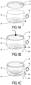
- a membrane 10 comprising a thermoplastic material is provided which is connected along its outer ridge 12 to a membrane holder 14.
- the membrane holder can be a metal ring.
- the membrane holder 14 is manufactured from a corrosion resistant alloy.
- the thermoplastic material of the membrane is elastic, which allows an elastic deformation of the membrane when a pressure difference exists between the two opposing sides of the membrane.
- a mould 16 is provided and a vacuum device or blowing device 18 is provided for creating an underpressure or overpressure on one side of the membrane, in order to deform the membrane.
- the mould 16 may be one half 50 of the housing of the expansion vessel, or at least a part of a housing of the expansion vessel.
- the combination of membrane holder 14 and membrane 10 is placed in the vessel halve 16 or in the special forming mould.
- the mould is a part of the housing, and the membrane holder is welded to the housing part via a laser weld.
- the housing part into which the membrane is blown moulded is formed prior to the connecting of the membrane material with the housing part.
- the welding operation may take place prior to the deforming process and is further discussed herein below. In this way a permanent connection is created between the membrane and the vessel halve prior to the forming of the membrane with the blow-moulding process.
- the mould is a separate mould.
- the membrane holder may be connected to the mould in a variety of ways.
- a heating device 20 is positioned at the bottom of the vessel halve or mould in order to provide heat to the membrane 10.
- a vacuum is created in the space 22 defined between the membrane 10 and the vessel halve 16, by sucking out the air through an opening 24 with the vacuum device 18 which is in fluid connection with the space between the membrane and the mould 16 via a conduit 26. Simultaneously, the membrane is heated with the heating device 20.
- the thermoplastic material in the membrane becomes soft and mouldable and deforms in a plastic way. The plasticity results from the thermoplastic nature of the material.
- the membrane substantially adopts the form of the vessel halve 16 or, in the embodiment falling outside the scope of the claims, special forming mould 16.
- the heating device When the membrane has deformed, the heating device is turned off and the membrane cools back to the original temperature.
- the membrane adopts its new, non-flat form, while remaining deformable due to its elasticity, as the membrane should be in order to let the expansion vessel function properly.
- the membrane is composed of multiple layers. This aspect is further discussed in relation to figure 4 .
- the layers of the membrane are all elastic, in order to allow the membrane to deform in its normal use temperature, when in use the pressures inside the expansion vessel varies.
- the membrane holder and membrane 10 are first deformed in the special forming mould, are subsequently disconnected and removed from the mould, are placed in the housing and welded to the housing.
- the membrane 10 is left in place. After the deforming process, the heating device and the vacuum/blowing device are removed from the housing part. Next, the remaining parts of the expansion vessel are fitted.
- the membrane holder 14 comprises an inner ring 30 and an outer ring 32, which fit into one another and form a click-connection.
- An outer region 12 of the membrane 10 is positioned between the two rings 30, 32.
- the membrane 10 may not comprise a thickened outer ridge.
- the inner ring comprises a receding part 36 which extends along the outer circumference of the inner ring.
- the outer ring comprises a protruding part 38 which extends along the inner circumference of the outer ring. However, this may also be vice versa, with a protruding part on the inner ring and receding part on the outer ring.
- the receding part and the protruding part mate with one another to form the click-connection when the inner ring is moved into the outer ring in the direction of arrow 40.
- the receding part 36 may be concave, while the protruding part 38 may be convex.
- the outer region 12 extends upward between the inner and outer ring.
- the outer ring may comprise a seat portion 42 for a seal.
- a rubber sealing ring 44 may be provided at the seat portion 42 of the outer ring, to provide air-tightness and fluid tightness between the inner ring and outer ring. This function of air-tightness and fluid tightness may also be provided by the membrane 10 itself.
- the outer ring also defines a curve 45, in this case at the seat portion 42
- the inner ring defines a mating curve 47.
- the curve has the function of curving the outer region 12 of the membrane, toward the mating parts 36, 38.
- the outer ring 32 further comprises a membrane guide 46A which is curved and prevents damage to the membrane when the membrane is deformed.
- the inner ring 30 comprises a similar membrane guide 46B which is curved and which prevents damage to the membrane 10 when the membrane is deformed in an opposite direction.
- the membrane When travelling from a middle portion 140 of the membrane to an outer ridge 11 of the membrane, the membrane first starts to curve at a meeting location 142 where the membrane meets the inner ring and the outer ring. The curvature is in a first direction of curvature. Subsequently, the membrane curves in an opposite direction of curvature at the curve 45, 47 toward the mating parts 36, 38. The membrane subsequently curves through the curved form defined by the mating parts 36, 38. When travelling towards the ridge 11, the membrane first curves inwardly toward the center of the membrane holder and subsequently curves outwardly away from the center of the annular membrane holder. Above the mating parts 36, 38, the membrane extends over a small distance and ends at the ridge 11 of the membrane.
- the four curves can be defines as four curve regions of the membrane.
- the membrane comprises the following four curve regions:
- the membrane holder and membrane When the membrane holder and membrane are connected, the membrane may be deformed, as is discussed in relation to figures 1A-1C .
- the housing 48 comprises a first housing part 50 (also referred to as a first vessel halve) and a second housing part 52 (also referred to as a second vessel halve), which have overlapping sections 54, 56.
- the housing parts 50, 52 may be halves but need not be of the same size.
- the housing parts 50, 52 are preferably made of steel.
- the housing has a circular, cylindrical shape.
- the wall of the housing parts 50, 52 has an inner side and an outer side.
- the overlapping sections 54, 56 overlap in a region of overlap 58.
- the housing can comprise a one-piece unit, which is easy to manufacture.
- the housing can be of any shape, preferably, of a right circular cylinder shape.
- the housing comprises a wall having an inner side and an outer side.
- the housing can be made of metal or any other suitable material, such a synthetic material, in particular a hard plastic.
- the method comprises inserting the membrane holder 14 into the housing of the expansion vessel in such a way that an outer perimeter 60 of the membrane holder 14 is circumferentially abutted to an inner wall of the housing part 50.
- a laser welding device 100 is provided from the outside and a laser beam 102 is directed toward the housing parts 50, 52 and the membrane holder 14.
- the housing parts 50, 52 and the membrane holder 14 are welded to one another.
- the three parts may be connected to one another in a single circumferential weld.
- the circumferential weld creates and air-tight and fluid tight connection between the membrane holder 14 and the housing which is formed by housing parts 50, 52.
- the laser beam provides a high energy deeply into the contact area between the housing and the membrane holder, and generates a narrow and deep weld.
- the depth of the weld can be up to 25 mm.
- the membrane 10 divides the volume formed by the housing into two parts, with a first part acting as a first chamber for storing water, and with a second part acting as a second chamber for storing gas.
- the housing per se forms a protection layer with respect to the membrane holder for protecting the membrane holder from the corrosion or damage by, e.g. a collision. This prolongs the usage period of the expansion vessel.
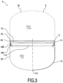
- the expansion vessel comprises a housing 9.
- the membrane holder 14 is first connected to a housing part 50 (or vessel halve). To this end, the assembly of the inner ring, outer ring and membrane is positioned at the inner side of the housing part 50.
- the membrane holder is connected to said housing part 50.
- the housing part 50 is connected at its ridge 62 to another housing part 52 shown in dashed lines. Both the connection between the membrane holder and the first housing part and between the first housing part and the second housing part are performed by laser welding from the outside.
- the membrane divides the total volume in a first volume 150 and a second volume 152.
- the membrane holder 14 is welded to the inner wall of the housing by the laser welding device by directing the laser beam at a contact area between the membrane holder 14 and the inner wall of the housing.
- the laser beam provided by the laser welding device penetrates through the inner wall of the housing and a tip of the laser beam at least reaches a portion of the membrane holder 14 to form a weld between the housing part 50 and the membrane holder 14.
- the weld comprises a line weld which extends circumferentially around the expansion vessel.
- the line weld is provided at the contact area between the membrane holder 14 and the inner side of the wall of the housing part 50.
- the line weld provides a first fluid tight connection between the membrane holder 14 and the housing 9.
- the laser beam 102 is moved along the entire outer circumference of the housing, i.e. perpendicular to the plane of drawing, and performs an annular weld which connects the membrane holder to the housing.
- the membrane comprises a first, protective layer 201, a second, gas-impermeable layer 202 and a third, protective layer 203.
- the three layers are interconnected via first and second adhesive layers 204.
- the second, gas-impermeable layer may be composed of Ethylene Vinyl Alcohol (EVOH).
- EVOH Ethylene Vinyl Alcohol
- EVOH is known for its good impermeability.
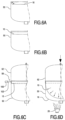
- FIG. 5a shows how the membrane 10 is directly bonded to the membrane holder 14.
- the bonding may be chemical bonding.
- a bonding agent may be used. Bonding agents are known in the field of the art.
- the bonding may also be physical bonding.
- the surface area of the bonded connection is rather large, i.e. the membrane can be bonded over a considerable width 70 onto the membrane holder 14, see fig. 5B .
- the width 70 extends parallel to the housing.
- the connection extends circumferentially around the inner side of the membrane holder 14.
- Figure 5c shows how the membrane holder is welded to the housing parts 50, 52 while at the same time connecting the housing parts 50, 52 to one another.
- This connection is performed by laser welding from the outside.
- the parts 50, 52 and 14 form a region of overlap 58. If the laser weld deteriorates the quality of the cured connection between the membrane 10 and the membrane holder 14, this will only locally affect the cured connection and not deteriorate the overall quality of the connection between the membrane and the membrane holder, because a width of the weld is substantially smaller than the width 70 of the cured connection.
- a first laser weld is performed to weld the membrane holder 14 to housing part 50 and in a second, separate laser weld, the housing part 52 is welded to housing part 50.
- overpressure is applied by blowing air or another gas via the opening 24 into the expansion vessel.
- the membrane 10 is deformed against the housing part 50, and heated with a heating device 20.
- the membrane 10 becomes plastic and deforms plastically.
- the housing part is used as a mould 16.
- the heating device 20 is removed or switched off; the membrane 10 cools and becomes elastic again.
- FIG. 6A, 6B, 6C, 6D a similar process as in Figures 5A - 5D is shown, except that the membrane 10 is connected directly onto a housing part 50 by bonding.
- the bonding may be chemical or physical bonding.
- a bonding agent may be used.
- the housing part 50 including the membrane 10 is connected to another housing part 52.
- the membrane is plastically deformed by a combination of pressure and heating, wherein the housing part 50 is used as a mould.
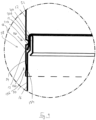
- FIG 7 another embodiment of the expansion vessel is shown in connection with another method of manufacturing the expansion vessel.
- a roll 200 of membrane material is provided from which the membrane material 202 is spooled.
- a first housing part 50 is provided, also called a first vessel halve 16.
- the membrane material which comes from the roll is flat.
- the membrane material in particular a region which is intended to form the outer region of the membrane, is engaged with the first housing part 50, in particular on the ridge 204 of the first housing part 50.
- a second housing part 52 also referred to as a second vessel halve 17, is engaged with the first vessel halve 16. Excess material of the membrane can be cut away.
- This embodiment does not have a separate membrane holder, i.e. the membrane 10 is connected to the housing parts 50, 52 directly.
- a membrane holder may be used.
- the second housing part 52 is placed over the first housing part 50. To this end a region 58 of overlap is formed.
- the region comprises:
- the first housing part 50 has an overlapping section 54 comprising an inwardly receding section 206.
- the inwardly receding section 206 forms the clenching region 132 with a part 210 of the overlapping section 56 of the second vessel halve 17.
- the membrane is clenched between the vessel halves.
- the part 210 may be an inwardly protruding section of the second vessel halve, in particular an inwardly protruding rim 210.
- the part 210 presses against the inwardly receding section 206n and clenches the outer region 12 of the membrane there between.
- the outer region 12 of the membrane extends downward relative to the middle portion 140 of the membrane 10 and is clenched between an upwardly directed receding section 206 and the part 210 of the second housing part 52.
- the connecting region 132 is formed by a wall section 134 of the first housing part 50 and a wall part 136 of the second housing part 52.
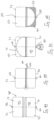
- Figure 8A shows that the first housing part 50 is slightly smaller than the second housing part 52.
- Figure 8A shows that the first volume 150 is slightly smaller than the second volume 152.
- Figure 8B shows that after the first and second housing parts are engaged, they are connected with laser welding.
- Figure 8C shows that the membrane 10 is blow-moulded against the housing, and in particular against the larger housing part 152. This has the positive effect that in use, the membrane will never undergo pure extension, or stretch, with accompanying tensile stresses.
- Figure 8D shows that in the use situation the smaller volume 150 is filled with the liquid or gas that needs to be able to expand, and the larger volume 152 is filled with the gas that provides the back pressure on the membrane.
- Opening 160 is an opening for a medium which needs to be able to expand and which is typically configured to be connected to a conduit system.
- the opening 162 is an opening for a gas which provides the back pressure.
Landscapes
- Engineering & Computer Science (AREA)
- Mechanical Engineering (AREA)
- Physics & Mathematics (AREA)
- Thermal Sciences (AREA)
- Chemical & Material Sciences (AREA)
- Combustion & Propulsion (AREA)
- General Engineering & Computer Science (AREA)
- Filling Or Discharging Of Gas Storage Vessels (AREA)
- Moulds For Moulding Plastics Or The Like (AREA)
- Blow-Moulding Or Thermoforming Of Plastics Or The Like (AREA)
- Separation Using Semi-Permeable Membranes (AREA)
Claims (10)
- Verfahren zum Herstellen eines Expansionsgefäßes (8), das ein Gehäuse (9) und eine Membran (10), die das Gehäuse in zwei Volumen unterteilt, umfasst, wobei das Verfahren Folgendes umfasst:- Bereitstellen des Gehäuses (9),- Bereitstellen einer Membran (10), die ein thermoplastisches Material umfasst,- Bereitstellen eines Formwerkzeugs (16), das eine nicht ebene Form aufweist,- Bereitstellen einer Unterdruck/Blas-Vorrichtung (18), die ausgelegt ist, die Membran entsprechend der Form des Formwerkzeugs zu verformen, indem auf einer Seite der Membran ein Überdruck oder ein Unterdruck bereitgestellt wird,- Bereitstellen einer Heizvorrichtung (20), die zum Bereitstellen von Wärme an der Membran während des Unterdruck/Blas-Formprozesses konfiguriert ist,wobei das Verfahren die folgenden weiteren Schritte umfasst:- Verformen der Membran mit der Unterdruck/Blas-Vorrichtung entsprechend der Form des Formwerkzeugs, während mit der Heizvorrichtung Wärme an der Membran bereitgestellt wird, wodurch ermöglicht wird, dass sich das thermoplastische Material plastisch verformt,- Abkühlen der verformten Membran unter die Temperatur, bei der sich das thermoplastische Material verformt, wodurch das thermoplastische Material in einer nicht ebenen Form entsprechend der Form des Formwerkzeugs ausgebildet wird, und- Verbinden der Membran direkt oder indirekt mit dem Gehäuse des Expansionsgefäßes,wobei das Verfahren das Verwenden des Gehäuses oder eines Abschnitts des Gehäuses des Expansionsgefäßes als das Formwerkzeug umfasst.
- Verfahren nach Anspruch 1, das Folgendes umfasst:- Bereitstellen eines Gehäuses, das einen ersten Gehäuseabschnitt (50) und einen zweiten Gehäuseabschnitt (52) umfasst,- Verbinden der Membran direkt oder indirekt über einen Membranhalter mit einem Gehäuseabschnitt,- Blasformen der Membran im Gehäuse, gefolgt vom Abkühlen der Membran, um die Membran in ihrer neuen, nicht ebenen Form bereitzustellen,- Verbinden des ersten Gehäuseabschnitts und des zweiten Gehäuseabschnitts direkt oder indirekt über den Membranhalter, wodurch das Gehäuse gebildet wird.
- Verfahren nach Anspruch 2, wobei die Membran vor dem Bilden der Membran mit dem Blasformprozess direkt oder indirekt über den Membranhalter dauerhaft mit dem Gehäuse verbunden wird.
- Verfahren nach Anspruch 3, das die nachfolgenden Schritte umfasst:∘ In-Eingriff-Bringen des äußeren Bereichs der Membran direkt oder indirekt mit einem ersten Gehäuseabschnitt,∘ Anordnen eines zweiten Gehäuseabschnitts gegen den ersten Gehäuseabschnitt, wodurch das Gefäß gebildet wird und die Membran arretiert wird,∘ Verbinden der Gehäuseabschnitte,∘ Blasformen der Membran.
- Verfahren nach Anspruch 4, wobei die Membran direkt zwischen den Gehäuseabschnitten umgeschlagen wird.
- Verfahren nach Anspruch 5, wobei ein Überlappungsbereich zwischen der ersten und der zweiten Gefäßhälfte gebildet wird, wobei der Bereich Folgendes umfasst:∘ einen Umschlagbereich, und∘ einen Verbindungsbereich,wobei die Membran im Umschlagbereich zwischen den Gefäßhälften umgeschlagen wird und wobei die Gefäßhälften im Verbindungsbereich miteinander verbunden werden.
- Verfahren nach einem der Ansprüche 3-6, das das Ziehen von Membranmaterial von einer Rolle eines Membranmaterials, das In-Eingriff-Bringen des Membranmaterials mit einem ersten Gehäuseabschnitt, das Anordnen des zweiten Gehäuseabschnitts über dem ersten Gehäuseabschnitt und das Wegschneiden von überschüssigem Material der Membran umfasst.
- Verfahren nach einem der vorhergehenden Ansprüche, wobei ein erster Gehäuseabschnitt kleiner als ein zweiter Gehäuseabschnitt ist und wobei im Blasformschritt die Membran gegen den zweiten, größeren Gehäuseabschnitt blasgeformt wird.
- Expansionsgefäß (8), das ein Gehäuse und eine Membran, die das Gehäuse in zwei Volumen unterteilt, umfasst, dadurch gekennzeichnet, dass das Expansionsgefäß mit dem Verfahren nach Anspruch 1 hergestellt wird, wobei die Membran (10) ein thermoplastisches Material umfasst und wobei die Membran in Ruhestellung, d. h. mit gleichem Druck auf beiden Seiten der Membran, eine nicht ebene Form aufweist.
- Anordnung zum Herstellen eines Expansionsgefäßes, wobei die Anordnung Folgendes umfasst:- ein Formwerkzeug (16, 50) zum Bilden einer Membran des Expansionsgefäßes, wobei das Formwerkzeug eine nicht ebene Form aufweist,- eine Unterdruck/Blas-Vorrichtung (18), die ausgelegt ist, die Membran entsprechend der Form des Formwerkzeugs zu verformen, indem ein Überdruck oder Unterdruck auf einer Seite der Membran bereitgestellt wird,- eine Heizvorrichtung (20), die zum Bereitstellen von Wärme an der Membran während des Unterdruck/Blas-Formprozesses konfiguriert ist,wobei die Anordnung einen Träger zum Tragen eines gebildeten Gehäuseabschnitts des Expansionsgefäßes umfasst, wobei die Unterdruck/Blas-Vorrichtung ausgelegt ist, zum Blasformen der Membran, während der Gehäuseabschnitt als ein Formwerkzeug verwendet wird, einen Unterdruck in dem Gehäuseabschnitt bereitzustellen oder einen Überdruck im anderen Gehäuseabschnitt bereitzustellen.
Applications Claiming Priority (3)
| Application Number | Priority Date | Filing Date | Title |
|---|---|---|---|
| US201261621045P | 2012-04-06 | 2012-04-06 | |
| NL2008613A NL2008613C2 (en) | 2012-04-06 | 2012-04-06 | Expansion vessel. |
| PCT/NL2013/050257 WO2013151441A2 (en) | 2012-04-06 | 2013-04-08 | Expansion vessel |
Publications (3)
| Publication Number | Publication Date |
|---|---|
| EP2834568A2 EP2834568A2 (de) | 2015-02-11 |
| EP2834568B1 true EP2834568B1 (de) | 2025-05-28 |
| EP2834568C0 EP2834568C0 (de) | 2025-05-28 |
Family
ID=49301131
Family Applications (1)
| Application Number | Title | Priority Date | Filing Date |
|---|---|---|---|
| EP13720099.4A Active EP2834568B1 (de) | 2012-04-06 | 2013-04-08 | Expansionsgefäss |
Country Status (3)
| Country | Link |
|---|---|
| EP (1) | EP2834568B1 (de) |
| NL (1) | NL2008613C2 (de) |
| WO (1) | WO2013151441A2 (de) |
Families Citing this family (2)
| Publication number | Priority date | Publication date | Assignee | Title |
|---|---|---|---|---|
| CN112041614A (zh) * | 2018-04-19 | 2020-12-04 | 福瑞科有限公司 | 单层膨胀水箱隔膜 |
| CN112041615B (zh) * | 2018-04-19 | 2022-11-29 | 福瑞科有限公司 | 单层膨胀水箱隔膜 |
Family Cites Families (4)
| Publication number | Priority date | Publication date | Assignee | Title |
|---|---|---|---|---|
| DE19740674C2 (de) * | 1997-02-20 | 2000-10-26 | Reflex Winkelmann & Pannhoff G | Blasenförmige Membran |
| DE19733982C1 (de) * | 1997-08-06 | 1998-10-01 | Winkelmann & Pannhoff Gmbh | Ausdehnungsgefäß sowie Verfahren zu seiner Herstellung |
| US6066287A (en) * | 1998-07-10 | 2000-05-23 | Plastic Technologies, Inc. | Gas assist injection molding |
| EP1876395A1 (de) | 2006-07-08 | 2008-01-09 | Winkelmann Sp. z o.o. | Membrandruckausdehnungsgefäss |
-
2012
- 2012-04-06 NL NL2008613A patent/NL2008613C2/en active
-
2013
- 2013-04-08 WO PCT/NL2013/050257 patent/WO2013151441A2/en not_active Ceased
- 2013-04-08 EP EP13720099.4A patent/EP2834568B1/de active Active
Also Published As
| Publication number | Publication date |
|---|---|
| WO2013151441A3 (en) | 2014-08-28 |
| WO2013151441A2 (en) | 2013-10-10 |
| EP2834568A2 (de) | 2015-02-11 |
| NL2008613C2 (en) | 2013-10-09 |
| EP2834568C0 (de) | 2025-05-28 |
Similar Documents
| Publication | Publication Date | Title |
|---|---|---|
| EP2671011B1 (de) | Klemmring | |
| EP2775190B1 (de) | Rohrverbindung | |
| US8622399B2 (en) | Composite sealing gasket and process for belling plastic pipe | |
| RU2425750C1 (ru) | Способ изготовления резервуара из термопластичной пластмассы путем экструзионно-раздувного формования, а также присоединительный элемент для использования при таком способе | |
| US9132728B2 (en) | Thermoplastic tank | |
| WO2014148240A1 (ja) | ダストカバー組立体 | |
| EP2834568B1 (de) | Expansionsgefäss | |
| CA2953930C (en) | System, method and apparatus for low profile seal | |
| KR20160041849A (ko) | 연료 탱크와 같은 차량 플라스틱 물품용의 부품 | |
| US20070156105A1 (en) | Plastics molding for ostomy device | |
| US12313090B2 (en) | Hydro-pneumatic pressure vessel and diaphragm assembly method | |
| JP2010151286A (ja) | 金属ベローズ式アキュムレータ | |
| US9937654B2 (en) | Molding device of inbuilt component fixing section of fuel tank | |
| JP5183293B2 (ja) | ブロー成形におけるインサート方法 | |
| JP5782859B2 (ja) | コールドパリソン方式による軟質樹脂用ブロー成形方法 | |
| CN110450443A (zh) | 中空体排气结构成型辅具、排气结构及中空体成型方法 | |
| US20250164118A1 (en) | Composite diaphragm expansion vessels | |
| CA2503947C (en) | Fuel system component and method of manufacture | |
| JP5006179B2 (ja) | 安全タイヤ用隔膜、安全タイヤ、及び安全タイヤとリムとの組立体、並びに安全タイヤ用隔膜の製造方法 | |
| KR101280334B1 (ko) | 연료 시스템 구성요소 및 그의 제조 방법 | |
| JP2008296775A (ja) | 安全タイヤ用環状構造体、安全タイヤおよび安全タイヤ組立体 |
Legal Events
| Date | Code | Title | Description |
|---|---|---|---|
| PUAI | Public reference made under article 153(3) epc to a published international application that has entered the european phase |
Free format text: ORIGINAL CODE: 0009012 |
|
| 17P | Request for examination filed |
Effective date: 20141031 |
|
| AK | Designated contracting states |
Kind code of ref document: A2 Designated state(s): AL AT BE BG CH CY CZ DE DK EE ES FI FR GB GR HR HU IE IS IT LI LT LU LV MC MK MT NL NO PL PT RO RS SE SI SK SM TR |
|
| AX | Request for extension of the european patent |
Extension state: BA ME |
|
| DAX | Request for extension of the european patent (deleted) | ||
| STAA | Information on the status of an ep patent application or granted ep patent |
Free format text: STATUS: EXAMINATION IS IN PROGRESS |
|
| 17Q | First examination report despatched |
Effective date: 20220304 |
|
| GRAP | Despatch of communication of intention to grant a patent |
Free format text: ORIGINAL CODE: EPIDOSNIGR1 |
|
| STAA | Information on the status of an ep patent application or granted ep patent |
Free format text: STATUS: GRANT OF PATENT IS INTENDED |
|
| INTG | Intention to grant announced |
Effective date: 20230403 |
|
| GRAJ | Information related to disapproval of communication of intention to grant by the applicant or resumption of examination proceedings by the epo deleted |
Free format text: ORIGINAL CODE: EPIDOSDIGR1 |
|
| STAA | Information on the status of an ep patent application or granted ep patent |
Free format text: STATUS: EXAMINATION IS IN PROGRESS |
|
| INTC | Intention to grant announced (deleted) | ||
| GRAP | Despatch of communication of intention to grant a patent |
Free format text: ORIGINAL CODE: EPIDOSNIGR1 |
|
| STAA | Information on the status of an ep patent application or granted ep patent |
Free format text: STATUS: GRANT OF PATENT IS INTENDED |
|
| INTG | Intention to grant announced |
Effective date: 20241008 |
|
| GRAS | Grant fee paid |
Free format text: ORIGINAL CODE: EPIDOSNIGR3 |
|
| RAP3 | Party data changed (applicant data changed or rights of an application transferred) |
Owner name: AALBERTS HFC B.V. |
|
| RAP3 | Party data changed (applicant data changed or rights of an application transferred) |
Owner name: AALBERTS HFC B.V. |
|
| GRAA | (expected) grant |
Free format text: ORIGINAL CODE: 0009210 |
|
| STAA | Information on the status of an ep patent application or granted ep patent |
Free format text: STATUS: THE PATENT HAS BEEN GRANTED |
|
| AK | Designated contracting states |
Kind code of ref document: B1 Designated state(s): AL AT BE BG CH CY CZ DE DK EE ES FI FR GB GR HR HU IE IS IT LI LT LU LV MC MK MT NL NO PL PT RO RS SE SI SK SM TR |
|
| REG | Reference to a national code |
Ref country code: GB Ref legal event code: FG4D |
|
| REG | Reference to a national code |
Ref country code: CH Ref legal event code: EP |
|
| REG | Reference to a national code |
Ref country code: DE Ref legal event code: R096 Ref document number: 602013086790 Country of ref document: DE |
|
| REG | Reference to a national code |
Ref country code: IE Ref legal event code: FG4D |
|
| U01 | Request for unitary effect filed |
Effective date: 20250624 |
|
| U07 | Unitary effect registered |
Designated state(s): AT BE BG DE DK EE FI FR IT LT LU LV MT NL PT RO SE SI Effective date: 20250701 |
|
| PG25 | Lapsed in a contracting state [announced via postgrant information from national office to epo] |
Ref country code: ES Free format text: LAPSE BECAUSE OF FAILURE TO SUBMIT A TRANSLATION OF THE DESCRIPTION OR TO PAY THE FEE WITHIN THE PRESCRIBED TIME-LIMIT Effective date: 20250528 |
|
| PG25 | Lapsed in a contracting state [announced via postgrant information from national office to epo] |
Ref country code: GR Free format text: LAPSE BECAUSE OF FAILURE TO SUBMIT A TRANSLATION OF THE DESCRIPTION OR TO PAY THE FEE WITHIN THE PRESCRIBED TIME-LIMIT Effective date: 20250829 Ref country code: NO Free format text: LAPSE BECAUSE OF FAILURE TO SUBMIT A TRANSLATION OF THE DESCRIPTION OR TO PAY THE FEE WITHIN THE PRESCRIBED TIME-LIMIT Effective date: 20250828 |
|
| PG25 | Lapsed in a contracting state [announced via postgrant information from national office to epo] |
Ref country code: PL Free format text: LAPSE BECAUSE OF FAILURE TO SUBMIT A TRANSLATION OF THE DESCRIPTION OR TO PAY THE FEE WITHIN THE PRESCRIBED TIME-LIMIT Effective date: 20250528 |
|
| PG25 | Lapsed in a contracting state [announced via postgrant information from national office to epo] |
Ref country code: HR Free format text: LAPSE BECAUSE OF FAILURE TO SUBMIT A TRANSLATION OF THE DESCRIPTION OR TO PAY THE FEE WITHIN THE PRESCRIBED TIME-LIMIT Effective date: 20250528 |
|
| PG25 | Lapsed in a contracting state [announced via postgrant information from national office to epo] |
Ref country code: RS Free format text: LAPSE BECAUSE OF FAILURE TO SUBMIT A TRANSLATION OF THE DESCRIPTION OR TO PAY THE FEE WITHIN THE PRESCRIBED TIME-LIMIT Effective date: 20250828 |
|
| PG25 | Lapsed in a contracting state [announced via postgrant information from national office to epo] |
Ref country code: IS Free format text: LAPSE BECAUSE OF FAILURE TO SUBMIT A TRANSLATION OF THE DESCRIPTION OR TO PAY THE FEE WITHIN THE PRESCRIBED TIME-LIMIT Effective date: 20250928 |
|
| PG25 | Lapsed in a contracting state [announced via postgrant information from national office to epo] |
Ref country code: SM Free format text: LAPSE BECAUSE OF FAILURE TO SUBMIT A TRANSLATION OF THE DESCRIPTION OR TO PAY THE FEE WITHIN THE PRESCRIBED TIME-LIMIT Effective date: 20250528 |
|
| PG25 | Lapsed in a contracting state [announced via postgrant information from national office to epo] |
Ref country code: CZ Free format text: LAPSE BECAUSE OF FAILURE TO SUBMIT A TRANSLATION OF THE DESCRIPTION OR TO PAY THE FEE WITHIN THE PRESCRIBED TIME-LIMIT Effective date: 20250528 |
|
| PG25 | Lapsed in a contracting state [announced via postgrant information from national office to epo] |
Ref country code: SK Free format text: LAPSE BECAUSE OF FAILURE TO SUBMIT A TRANSLATION OF THE DESCRIPTION OR TO PAY THE FEE WITHIN THE PRESCRIBED TIME-LIMIT Effective date: 20250528 |
|
| PLBE | No opposition filed within time limit |
Free format text: ORIGINAL CODE: 0009261 |
|
| STAA | Information on the status of an ep patent application or granted ep patent |
Free format text: STATUS: NO OPPOSITION FILED WITHIN TIME LIMIT |
|
| REG | Reference to a national code |
Ref country code: CH Ref legal event code: L10 Free format text: ST27 STATUS EVENT CODE: U-0-0-L10-L00 (AS PROVIDED BY THE NATIONAL OFFICE) Effective date: 20260409 |