EP2834041B1 - Power wrench - Google Patents
Power wrench Download PDFInfo
- Publication number
- EP2834041B1 EP2834041B1 EP13723402.7A EP13723402A EP2834041B1 EP 2834041 B1 EP2834041 B1 EP 2834041B1 EP 13723402 A EP13723402 A EP 13723402A EP 2834041 B1 EP2834041 B1 EP 2834041B1
- Authority
- EP
- European Patent Office
- Prior art keywords
- torque
- motor
- power wrench
- gear
- backward direction
- Prior art date
- Legal status (The legal status is an assumption and is not a legal conclusion. Google has not performed a legal analysis and makes no representation as to the accuracy of the status listed.)
- Active
Links
Images

Classifications
-
- B—PERFORMING OPERATIONS; TRANSPORTING
- B25—HAND TOOLS; PORTABLE POWER-DRIVEN TOOLS; MANIPULATORS
- B25B—TOOLS OR BENCH DEVICES NOT OTHERWISE PROVIDED FOR, FOR FASTENING, CONNECTING, DISENGAGING OR HOLDING
- B25B21/00—Portable power-driven screw or nut setting or loosening tools; Attachments for drilling apparatus serving the same purpose
- B25B21/02—Portable power-driven screw or nut setting or loosening tools; Attachments for drilling apparatus serving the same purpose with means for imparting impact to screwdriver blade or nut socket
Definitions
- the invention relates to an electric power wrench for providing a torque in two opposed rotational directions. Specifically, the invention relates to a power wrench that may be driven as pulsating power wrench by means of an electric motor and a control unit. Further, the invention relates to a method of controlling an electric motor in such a power wrench.
- a conventional power wrench such as e.g. a nutrunner, comprises a transmission for providing a torque from a motor to a main shaft.
- the motor is arranged to drive the rotation of the main shaft in two opposed directions, a first forward direction and a second reversed direction.
- the transmission needs to be adapted to drive the rotation both in the forward direction and the reversed direction.
- the reversed drive is only exceptionally used when e.g. a joint is unfastened. This implies that the main focus of the motor and the transmission is on the forward drive.
- a problem that needs to be addressed in a hand held power wrench is that the torque provided by the tool needs to be compensated for, such that a counter force is provided for every torque provided by the tool.
- a counter force is provided for every torque provided by the tool.
- a pulsating power tool is described in US patent No. 6,680,595 . This may also be the case in sophisticated continuously driven or non-pulsating tools. In other tools, the counter forces have to be provided by the operator who is holding the tool.
- the rotational speed of the motor may be adapted to smoothen or level out the torque provided in the forward direction. This is possible because the torque is relatively low in a first stage, such that inertia is build up to balance out part of the torque as it increases towards the end of the operation.
- the reversed direction the conditions are however normally different, because the reversed direction is normally utilised to loosen a joint, which is fastened by a relatively high clamp force, which may only be released by a correspondingly high torque.
- a high torque needs to be delivered right away, such that it is not possible to build up inertia in the machine.
- An object of the invention is to provide a power wrench with an improved functionality when driven in the reverse direction.
- the invention relates to an electric power wrench for fastening and loosening joints, which power wrench comprises:
- said torque pulses are produced by firstly rotating the motor in the forward direction in order to increase the play and subsequently accelerating the motor in the backward direction so as to produce a torque pulse in the backward direction.
- said torque pulses are produced intermittently for as long as the motor is driven in the backward direction in said first mode.
- the power wrench includes a gear that may be selectively positioned in either a first or a second coupling position wherein the first coupling position provides a continuous transmission of the rotation of an input shaft to an output shaft and the second coupling position provides a transmission that includes a limited freedom of motion in which the input shaft may be rotated without affecting the output shaft before engaging the output shaft in at least the backward direction, wherein the control unit is arranged to control the motor such that in the first driving mode the first coupling position is used in a forward direction and the second coupling position is used in a backward direction.
- the gear may be a sleeve, which may be translated between the first coupling position and the second coupling position.
- An electronic sensor may be provided to register the position of the gear and to signal to the control unit in which of the coupling positions the gear is positioned.
- the power wrench is provided with a display for monitoring a current position of the gear.
- the power wrench may have a second driving mode in which the motor is driven continuously in both directions, and a third driving mode in which the motor is driven intermittently in both directions.
- the invention relates to a method of controlling an electric motor in a power wrench for fastening and loosening joints, which power wrench comprises:
- the parameter registered in step (c) is the applied torque, wherein all steps (a)-(e) are repeated if the registered torque exceeds the threshold value.
- the operation is concluded if the registered torque underpasses the threshold value.
- An advantage of the invention is that the performance of the tool as it operates in the second rotational direction is improved without affecting the performance of the tool when operating in the first rotational direction.
- the invention relates to a nutrunner.
- the main concept of the invention is not shown in a figure.
- the main concept consists of an electric power wrench for fastening and loosening joints.
- the power wrench comprises a main shaft for delivering a torque to a joint, an electric motor that is arranged to selectively drive the main shaft in two opposed rotational directions, and a control unit for controlling the drive of the electric motor.
- a transmission is arranged to connect the electric motor to the main shaft.
- the transmission includes an inherent play and wherein the torque pulses are produced in said play.
- Most transmission in power tools includes an inherent play, which normally amounts to just a fraction of a full rotation of the main shaft.
- the gist of the invention is to utilize this play in order to produce a torque pulse that will make it possible to e.g. loosening joints without producing massive counter forces that would be difficult to withstand for the operator holding the tool.
- the motor delivers torque pulses in the backward direction, which torque pulses are produced in said play.
- said torque pulses are produced by firstly rotating the motor in the forward direction in order to increase the play and subsequently accelerating the motor in the backward direction so as to produce a torque pulse in the backward direction. These pulses may be produced for as long as the joint is not fully loosened.
- a gear unit 10 in a power wrench according to a specific embodiment of the invention is schematically shown in two different coupling positions.
- the gear unit 10 includes an input shaft 11, an output shaft 12, and a gear 13.
- the input shaft 11 and the output shaft 12 are separated by a gap 19, which is housed inside the gear 13.
- the gear 13 is shown as being transparent, except for two ribs 14 and 15 that are an integral part of the gear 13.
- An electric motor (not shown) is arranged to provide a driving force for driving the rotation of the input shaft 11.
- the motor is arranged to drive the input shaft 11 in two opposed directions R in-1 and R in-2 .
- the gear 13 is arranged to transmit the rotation of the input shaft 11 to the output shaft 12, such that the output shaft 12 will rotate in the corresponding directions R out-1 and R out-2 .
- the output shaft 12 is connected to a main shaft (not shown) that includes a socket for holding a tool bit.
- the output shaft 12 constitutes the main shaft.
- the input shaft 11 may in fact be the motor output shaft.
- the gear transmission may include further gear connections. For instance the rotational speed of the motor output shaft is normally geared down to the main shaft such that the main shaft rotates at a lower rotational speed than the motor output shaft.
- the gear 13 is positioned in a first coupling position G 1 , which provides a continuous transmission of the rotation of the input shaft 11 (R in-1 ) to the output shaft 12 (R out-1 ).
- the gear 13 is positioned in a second coupling position G 2 , which provides a transmission that includes a freedom of motion in at least one rotational direction of the input shaft 11 with respect to the output shaft 12.
- the gear 13 is a sleeve, which may be translated between the first coupling position G 1 and the second coupling position G 2 .
- the gear 13 involves an inner coupling of the splined type that includes longitudinal grooves and wedges that are adapted to engage with corresponding grooves and wedges on both the input shaft 11 and the output shaft 12.
- the input shaft 11 includes at least one longitudinal tongue 16 that extends about 90° in the circumferential direction of the input shaft 11.
- the output shaft 12 includes at least one corresponding longitudinal tongue 20.
- both tongues 16 and 20 are tightly fitted in sectional cavities 17 formed between a first pair of ribs 14 and a second pair of ribs 15.
- the ribs 14 and 15 are integrated parts of the gear, and are arranged to interact with the tongue 16 of the input shaft 11 and the tongue 20 of the output shaft 12.
- the play e.g. the freedom of motion between the input shaft 11 and the gear 13 should be as small as possible, such that the connection between the tongue 16 and the ribs 14 and 15 becomes as tight and rigid as possible.
- the freedom of motion should be none or minimal in this coupling position.
- the engagement between the pairs of ribs 14 and 15 and the tongue 16 of the input shaft 11 may be identical to the connection between ribs 14 and 15 and the tongue 20 of the output shaft 12. However, in contrast to the connection of the gear 13 to the output shaft 12, which is continuous, the connection of the gear 13 to the input shaft 11 is variable. As the gear 13 is translated into the second coupling position G 2 the coupling between the input shaft 11 and the gear 13 is altered. In the second coupling position G 2 , shown in figures 2 and 4-5 , the gear 13 has been translated such that a non continuous coupling has been accomplished between the input shaft 11 and the gear 13.
- the second pair of ribs 15 does not extend over the whole length of the gear 13. Therefore, as a consequence of the translational movement of the gear 13, the two opposed longitudinal tongues 16 are no longer in engagement with the second pair of ribs 15 when the gear 13 is in the second coupling position G 2 . Instead, the tongues 16 may rotate freely about 90° inside two opposed sectional cavities 18 formed between each side of the first pair of ribs 14. Hence, in this second coupling position G 2 , the input shaft 11 may rotate freely within a limited extent with respect to the gear 13 and the output shaft 12.
- the first coupling position G 1 is arranged to be used in a first of the two opposed directions and the second coupling position G 2 is arranged to be used only in the second of the two opposed directions.
- a secondary input rotational movement R in-2 of the input shaft is transmitted via the gear 13 to the output shaft 12 as a pulse P out and a subsequent secondary output rotational movement R out-2 .
- the rotational movement of the pulse P out is build up as the input shaft 11 rotates without affecting the gear 13 and the output shaft 12, whereby the impact between the tongues 16 and the first pair of ribs 14 delivers a pulse with a momentary elevated torque from the input shaft 11 to the output shaft 12 via the gear 13.
- the pulsating movement is repeated for as long as the trigger of the power wrench is actuated, or until the torque needed to continue the reversing operation is below a predetermined threshold value, such as e.g. 8 Nm.
- a nutrunner is utilised to fasten joints between e.g. bolts and nuts.
- the fastening is performed in a first direction.
- an instantaneous high torque is needed in order to release the nut from the bolt. This may be achieved by means of the inventive arrangement.
- the second coupling position includes a rotational freedom of motion in the form of sectional cavities 18 in which the tongues 16 of the input shaft 11 may rotate in the reversed direction without affecting the gear 13 and the output shaft 12.
- the second coupling position ( figs. 2 and 4-5 ) will provide a momentarily high torque that is build up for up to half a revolution or more of the input shaft 11 before impact transmission to the output shaft 12.
- the rotational play may of course be adapted to the torque needed for the application.
- the gear 13 may be pre-stressed, when in the second coupling position G 2 .
- the pre-stress will act to increase the rotational play between the input shaft 11 and the output shaft 12, e.g. to the position shown in figure 4 .
- the input shaft 11 itself may be pre-stressed, e.g. by means of a coil spring.
- the fact that the input shaft 11 is pre-stressed is advantageous as it guarantees the rotational play even when the power wrench is to be used and when the output shaft is fixed by the interaction between the main shaft and the joint.
- the repositioning between the first coupling position G 1 and the second coupling position G 2 may be achieved in an electrical manner, preferably simultaneously as the rotational direction of the motor is reversed.
- the coupling is achieved by a manual operation of a sleeve located on the outside of the tool.
- an electronic sensor may be provided to register the position of the gear 13 and to signal in which of the coupling positions it is positioned.
- the power wrench may be provided with a display for monitoring a current position of the gear 13.
- the power wrench includes a clutch for disconnecting the input shaft 11 completely from the output shaft 12.
- this is achieved in that the gear 13 may be positioned in a third position, i.e. a clutch position, in addition to the first and the second coupling position G 1 and G 2 .
- the clutch position is arranged to involve an unlimited freedom of motion such that the input shaft 11 may be rotated without affecting the output shaft 12 at all when the gear 13 is positioned in the clutch position.
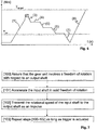
- Fig. 6 relates to a method of controlling the electric motor in a power wrench according to the invention.
- a joint between e.g. a screw and a bolt is tightened in a continuous manner.
- a target torque T target is set.
- the target torque T target should be met in order to verify the quality of the joint.
- the target torque T target is not met in the first step (1). Normally this is indicated in one way or another to the operator, e.g. on a display of the tool.
- the operator will try to remake the joint.
- a continuously operating power wrench it may not be possible to complete the joint by applying a positive torque corresponding to the missing torque. This is due to the fact that the torque needed to complete the joint is so high that the operator will not be able to provide the needed counteraction. Therefore the joint has to be loosened before it may be tightened again.
- the loosening of the joint will however function as an impulse tool, in which inertia is build up inside the tool, which inertia is transmitted to the output shaft in the form of one or several impulses.
- the inventive tool will function as a continuous power wrench in a first (clockwise) direction, and as an impulse tool in a second (counter clockwise) direction.
- the electric motor will be rotated in a forward direction assuring that the play is available in the transmission between the motor and the main shaft.
- a play is available between the input shaft 11 and the output shaft 12. This may be achieved in response to that direction pin on the wrench is set in reverse and that a trigger on the power wrench is pressed.
- the second step (2) of the curve in figure 6 corresponds to the provision of the freedom of motion between the input shaft 11 and the output shaft 12 as well as the rotation of the motor inside the freedom of motion.
- the motor in a first part of the horizontal line corresponding to step (2) the motor may be rotated in a forward direction, and in the second part of step (2) it will be accelerated in a the backward direction until the play has been eliminated, whereupon a torque pulse is generated and step (3) is initiated.
- step (3) the main shaft is rotated in a backward direction so as to loosen the joint, typically counter clockwise, such that the torque T in the joint decreases.
- Step (3) is followed by a horizontal step (4) which once again corresponds to the provision of the freedom of motion between the motor and the main shaft as well as the rotation of the motor inside said the freedom of motion.
- Steps (5)-(7) correspond to subsequent impulses, wherein the intermediate steps of repositioning the motor with respect to the main shaft are not indicated with numbers.
- FIG 6 the torque is illustrated so as to vary linearly with respect to time. This is however a simplification of a real operation and is not always the case.
- Figure 6 is intended to schematically illustrate an exemplary method in accordance with the invention.
- the method may comprise the steps of registering a parameter relating to the rotation of the output shaft 12, as a consequence of the impulse from the input shaft 11 to the output shaft 12, comparing said parameter with a threshold value, and based on said comparison, deciding if steps cited above should be repeated.
- the registered parameter is the applied torque, wherein the steps cited above are repeated if the registered torque exceeds the threshold value T thr . If the registered torque T underpasses the threshold value T thr the operation may be concluded. In the example shown in figure 6 , the registered torque T underpasses the threshold value T thr in step (7), which corresponds to the fourth consecutive impulse.
- the angular position ⁇ of the output shaft 12 or the main shaft may be registered.
- the registered angular position ⁇ may be compared to a target angular position ⁇ thr , such the reversing may be concluded, when the specific target angular position ⁇ thr is met.
- it may be possible to register the clamp force F acting in the joint e.g. by ultra sounds or by an estimation based on the applied torque. In such a case the actual clamp force F is compared to a threshold value F thr , in a corresponding manner.
- the step of registering a parameter is however optional.
- the consecutive steps of forwarding and reversing the motor are repeated until the operator releases the trigger.
- the function of the reverse mode of the power wrench, which is used when a joint is loosened corresponds to that of an impulse tool.
Landscapes
- Engineering & Computer Science (AREA)
- Mechanical Engineering (AREA)
- Details Of Spanners, Wrenches, And Screw Drivers And Accessories (AREA)
Applications Claiming Priority (2)
| Application Number | Priority Date | Filing Date | Title |
|---|---|---|---|
| SE1250332 | 2012-04-03 | ||
| PCT/EP2013/000984 WO2013149724A1 (en) | 2012-04-03 | 2013-04-03 | Power wrench |
Publications (2)
| Publication Number | Publication Date |
|---|---|
| EP2834041A1 EP2834041A1 (en) | 2015-02-11 |
| EP2834041B1 true EP2834041B1 (en) | 2019-10-09 |
Family
ID=48463908
Family Applications (1)
| Application Number | Title | Priority Date | Filing Date |
|---|---|---|---|
| EP13723402.7A Active EP2834041B1 (en) | 2012-04-03 | 2013-04-03 | Power wrench |
Country Status (7)
| Country | Link |
|---|---|
| US (1) | US9636809B2 (enExample) |
| EP (1) | EP2834041B1 (enExample) |
| JP (1) | JP6241475B2 (enExample) |
| KR (1) | KR102026499B1 (enExample) |
| CN (1) | CN104245235B (enExample) |
| BR (1) | BR112014024670B1 (enExample) |
| WO (1) | WO2013149724A1 (enExample) |
Families Citing this family (5)
| Publication number | Priority date | Publication date | Assignee | Title |
|---|---|---|---|---|
| CN104526621B (zh) * | 2015-01-04 | 2015-11-25 | 宁波工程学院 | 一种高性能的套筒工具 |
| SE539838C2 (en) * | 2015-10-15 | 2017-12-19 | Atlas Copco Ind Technique Ab | Electric handheld pulse tool |
| JP7618663B2 (ja) * | 2019-10-29 | 2025-01-21 | アトラス・コプコ・インダストリアル・テクニーク・アクチボラグ | 締結工具用ソケット |
| WO2021151674A1 (en) * | 2020-01-29 | 2021-08-05 | Atlas Copco Industrial Technique Ab | Electric tool adapted to perform tightening operations where torque is delivered in pulses |
| SE2330588A1 (en) * | 2023-12-21 | 2025-01-07 | Atlas Copco Ind Technique Ab | Pulse tool |
Family Cites Families (12)
| Publication number | Priority date | Publication date | Assignee | Title |
|---|---|---|---|---|
| US5105519A (en) * | 1985-06-19 | 1992-04-21 | Daiichi Dentsu Kabushiki Kaisha | Tension control method for nutrunner |
| JP3456949B2 (ja) * | 2000-06-19 | 2003-10-14 | 株式会社エスティック | ネジ締め装置の制御方法および装置 |
| DE602004032279D1 (de) * | 2003-02-05 | 2011-06-01 | Makita Corp | Kraftgetriebenes Werkzeug mit Drehmomentbegrenzung unter ausschliesslicher Benutzung eines Drehwinkelsensors |
| JP4362657B2 (ja) * | 2005-09-07 | 2009-11-11 | ヨコタ工業株式会社 | 電動式衝撃締め付け工具 |
| JP4699316B2 (ja) * | 2006-09-01 | 2011-06-08 | 株式会社エスティック | インパクト式のネジ締め装置 |
| US7562720B2 (en) * | 2006-10-26 | 2009-07-21 | Ingersoll-Rand Company | Electric motor impact tool |
| EP2140976B1 (de) * | 2008-07-01 | 2011-11-16 | Metabowerke GmbH | Schlagschrauber |
| JP5440766B2 (ja) * | 2009-07-29 | 2014-03-12 | 日立工機株式会社 | インパクト工具 |
| JP2011161580A (ja) * | 2010-02-11 | 2011-08-25 | Hitachi Koki Co Ltd | インパクト工具 |
| JP5483089B2 (ja) * | 2010-03-11 | 2014-05-07 | 日立工機株式会社 | インパクト工具 |
| CN102770248B (zh) * | 2010-03-31 | 2015-11-25 | 日立工机株式会社 | 电动工具 |
| JP5464014B2 (ja) * | 2010-03-31 | 2014-04-09 | 日立工機株式会社 | 電動工具 |
-
2013
- 2013-04-03 CN CN201380017910.4A patent/CN104245235B/zh active Active
- 2013-04-03 WO PCT/EP2013/000984 patent/WO2013149724A1/en not_active Ceased
- 2013-04-03 US US14/390,750 patent/US9636809B2/en active Active
- 2013-04-03 EP EP13723402.7A patent/EP2834041B1/en active Active
- 2013-04-03 JP JP2015503783A patent/JP6241475B2/ja active Active
- 2013-04-03 BR BR112014024670-0A patent/BR112014024670B1/pt active IP Right Grant
- 2013-04-03 KR KR1020147027462A patent/KR102026499B1/ko active Active
Non-Patent Citations (1)
| Title |
|---|
| None * |
Also Published As
| Publication number | Publication date |
|---|---|
| BR112014024670B1 (pt) | 2021-11-03 |
| KR20150001741A (ko) | 2015-01-06 |
| KR102026499B1 (ko) | 2019-09-27 |
| US9636809B2 (en) | 2017-05-02 |
| US20150090468A1 (en) | 2015-04-02 |
| BR112014024670A2 (enExample) | 2017-06-20 |
| EP2834041A1 (en) | 2015-02-11 |
| CN104245235B (zh) | 2017-06-06 |
| JP6241475B2 (ja) | 2017-12-06 |
| JP2015512796A (ja) | 2015-04-30 |
| CN104245235A (zh) | 2014-12-24 |
| WO2013149724A1 (en) | 2013-10-10 |
Similar Documents
| Publication | Publication Date | Title |
|---|---|---|
| EP2834041B1 (en) | Power wrench | |
| EP2055436B1 (en) | Reaction arm for power-driven torque intensifier | |
| EP2407274A1 (en) | Rotary impact tool | |
| JP7187339B2 (ja) | ブラインドナット締結装置 | |
| JP4891672B2 (ja) | ねじ部品締結機 | |
| CN114616410B (zh) | 动力工具以及用于动力工具的双速齿轮组件 | |
| GB2456674A (en) | Torque intensifying tool having an additional handle | |
| WO2015045871A1 (ja) | 自動ねじ締め制御および管理方法並びにシステム | |
| JP7169301B2 (ja) | 電気パルス工具 | |
| US11994171B2 (en) | Clamping shaft coupler | |
| US20090173194A1 (en) | Impact wrench structure | |
| JP2008184000A (ja) | 舵取装置 | |
| CN108687705B (zh) | 一种扭剪扳手的装配方法 | |
| KR200492689Y1 (ko) | 전동드라이버의 토크 제어장치 | |
| JP3215326U (ja) | 自動ねじ締め制御および管理システム | |
| US20240198478A1 (en) | Power tool having a disk-shaped tool, and Method for fastening or for releasing the tool | |
| JP3002748B2 (ja) | スクリュードライバー | |
| JP2008114303A (ja) | ねじ部品締結機 | |
| JP2010260111A (ja) | ねじ部品自動締結機の回転伝達装置 | |
| JP2010284739A (ja) | ねじ部品自動締結機における動力伝達装置 | |
| JP2003214097A (ja) | セグメントの継手装置 | |
| JP2010184342A (ja) | ねじ部品自動締結機 | |
| JP2009243569A (ja) | 金具の連結方法およびこれに用いる固定用治具並びに被可動金具 | |
| JP2017154185A (ja) | 締結装置 | |
| JP2016176494A (ja) | シフトバイワイヤ装置 |
Legal Events
| Date | Code | Title | Description |
|---|---|---|---|
| PUAI | Public reference made under article 153(3) epc to a published international application that has entered the european phase |
Free format text: ORIGINAL CODE: 0009012 |
|
| 17P | Request for examination filed |
Effective date: 20140929 |
|
| AK | Designated contracting states |
Kind code of ref document: A1 Designated state(s): AL AT BE BG CH CY CZ DE DK EE ES FI FR GB GR HR HU IE IS IT LI LT LU LV MC MK MT NL NO PL PT RO RS SE SI SK SM TR |
|
| AX | Request for extension of the european patent |
Extension state: BA ME |
|
| DAX | Request for extension of the european patent (deleted) | ||
| 17Q | First examination report despatched |
Effective date: 20151019 |
|
| GRAP | Despatch of communication of intention to grant a patent |
Free format text: ORIGINAL CODE: EPIDOSNIGR1 |
|
| STAA | Information on the status of an ep patent application or granted ep patent |
Free format text: STATUS: GRANT OF PATENT IS INTENDED |
|
| INTG | Intention to grant announced |
Effective date: 20190531 |
|
| RIN1 | Information on inventor provided before grant (corrected) |
Inventor name: LARS ELSMARK, KARL JOHAN |
|
| GRAS | Grant fee paid |
Free format text: ORIGINAL CODE: EPIDOSNIGR3 |
|
| GRAA | (expected) grant |
Free format text: ORIGINAL CODE: 0009210 |
|
| STAA | Information on the status of an ep patent application or granted ep patent |
Free format text: STATUS: THE PATENT HAS BEEN GRANTED |
|
| AK | Designated contracting states |
Kind code of ref document: B1 Designated state(s): AL AT BE BG CH CY CZ DE DK EE ES FI FR GB GR HR HU IE IS IT LI LT LU LV MC MK MT NL NO PL PT RO RS SE SI SK SM TR |
|
| REG | Reference to a national code |
Ref country code: GB Ref legal event code: FG4D |
|
| REG | Reference to a national code |
Ref country code: CH Ref legal event code: EP |
|
| REG | Reference to a national code |
Ref country code: IE Ref legal event code: FG4D |
|
| REG | Reference to a national code |
Ref country code: DE Ref legal event code: R096 Ref document number: 602013061438 Country of ref document: DE |
|
| REG | Reference to a national code |
Ref country code: AT Ref legal event code: REF Ref document number: 1188238 Country of ref document: AT Kind code of ref document: T Effective date: 20191115 |
|
| REG | Reference to a national code |
Ref country code: NL Ref legal event code: MP Effective date: 20191009 |
|
| REG | Reference to a national code |
Ref country code: LT Ref legal event code: MG4D |
|
| REG | Reference to a national code |
Ref country code: AT Ref legal event code: MK05 Ref document number: 1188238 Country of ref document: AT Kind code of ref document: T Effective date: 20191009 |
|
| PG25 | Lapsed in a contracting state [announced via postgrant information from national office to epo] |
Ref country code: FI Free format text: LAPSE BECAUSE OF FAILURE TO SUBMIT A TRANSLATION OF THE DESCRIPTION OR TO PAY THE FEE WITHIN THE PRESCRIBED TIME-LIMIT Effective date: 20191009 Ref country code: BG Free format text: LAPSE BECAUSE OF FAILURE TO SUBMIT A TRANSLATION OF THE DESCRIPTION OR TO PAY THE FEE WITHIN THE PRESCRIBED TIME-LIMIT Effective date: 20200109 Ref country code: GR Free format text: LAPSE BECAUSE OF FAILURE TO SUBMIT A TRANSLATION OF THE DESCRIPTION OR TO PAY THE FEE WITHIN THE PRESCRIBED TIME-LIMIT Effective date: 20200110 Ref country code: AT Free format text: LAPSE BECAUSE OF FAILURE TO SUBMIT A TRANSLATION OF THE DESCRIPTION OR TO PAY THE FEE WITHIN THE PRESCRIBED TIME-LIMIT Effective date: 20191009 Ref country code: SE Free format text: LAPSE BECAUSE OF FAILURE TO SUBMIT A TRANSLATION OF THE DESCRIPTION OR TO PAY THE FEE WITHIN THE PRESCRIBED TIME-LIMIT Effective date: 20191009 Ref country code: LV Free format text: LAPSE BECAUSE OF FAILURE TO SUBMIT A TRANSLATION OF THE DESCRIPTION OR TO PAY THE FEE WITHIN THE PRESCRIBED TIME-LIMIT Effective date: 20191009 Ref country code: NL Free format text: LAPSE BECAUSE OF FAILURE TO SUBMIT A TRANSLATION OF THE DESCRIPTION OR TO PAY THE FEE WITHIN THE PRESCRIBED TIME-LIMIT Effective date: 20191009 Ref country code: PT Free format text: LAPSE BECAUSE OF FAILURE TO SUBMIT A TRANSLATION OF THE DESCRIPTION OR TO PAY THE FEE WITHIN THE PRESCRIBED TIME-LIMIT Effective date: 20200210 Ref country code: ES Free format text: LAPSE BECAUSE OF FAILURE TO SUBMIT A TRANSLATION OF THE DESCRIPTION OR TO PAY THE FEE WITHIN THE PRESCRIBED TIME-LIMIT Effective date: 20191009 Ref country code: LT Free format text: LAPSE BECAUSE OF FAILURE TO SUBMIT A TRANSLATION OF THE DESCRIPTION OR TO PAY THE FEE WITHIN THE PRESCRIBED TIME-LIMIT Effective date: 20191009 Ref country code: NO Free format text: LAPSE BECAUSE OF FAILURE TO SUBMIT A TRANSLATION OF THE DESCRIPTION OR TO PAY THE FEE WITHIN THE PRESCRIBED TIME-LIMIT Effective date: 20200109 Ref country code: PL Free format text: LAPSE BECAUSE OF FAILURE TO SUBMIT A TRANSLATION OF THE DESCRIPTION OR TO PAY THE FEE WITHIN THE PRESCRIBED TIME-LIMIT Effective date: 20191009 |
|
| PG25 | Lapsed in a contracting state [announced via postgrant information from national office to epo] |
Ref country code: IS Free format text: LAPSE BECAUSE OF FAILURE TO SUBMIT A TRANSLATION OF THE DESCRIPTION OR TO PAY THE FEE WITHIN THE PRESCRIBED TIME-LIMIT Effective date: 20200224 Ref country code: RS Free format text: LAPSE BECAUSE OF FAILURE TO SUBMIT A TRANSLATION OF THE DESCRIPTION OR TO PAY THE FEE WITHIN THE PRESCRIBED TIME-LIMIT Effective date: 20191009 Ref country code: HR Free format text: LAPSE BECAUSE OF FAILURE TO SUBMIT A TRANSLATION OF THE DESCRIPTION OR TO PAY THE FEE WITHIN THE PRESCRIBED TIME-LIMIT Effective date: 20191009 |
|
| PG25 | Lapsed in a contracting state [announced via postgrant information from national office to epo] |
Ref country code: AL Free format text: LAPSE BECAUSE OF FAILURE TO SUBMIT A TRANSLATION OF THE DESCRIPTION OR TO PAY THE FEE WITHIN THE PRESCRIBED TIME-LIMIT Effective date: 20191009 |
|
| REG | Reference to a national code |
Ref country code: DE Ref legal event code: R097 Ref document number: 602013061438 Country of ref document: DE |
|
| PG2D | Information on lapse in contracting state deleted |
Ref country code: IS |
|
| PG25 | Lapsed in a contracting state [announced via postgrant information from national office to epo] |
Ref country code: DK Free format text: LAPSE BECAUSE OF FAILURE TO SUBMIT A TRANSLATION OF THE DESCRIPTION OR TO PAY THE FEE WITHIN THE PRESCRIBED TIME-LIMIT Effective date: 20191009 Ref country code: CZ Free format text: LAPSE BECAUSE OF FAILURE TO SUBMIT A TRANSLATION OF THE DESCRIPTION OR TO PAY THE FEE WITHIN THE PRESCRIBED TIME-LIMIT Effective date: 20191009 Ref country code: RO Free format text: LAPSE BECAUSE OF FAILURE TO SUBMIT A TRANSLATION OF THE DESCRIPTION OR TO PAY THE FEE WITHIN THE PRESCRIBED TIME-LIMIT Effective date: 20191009 Ref country code: EE Free format text: LAPSE BECAUSE OF FAILURE TO SUBMIT A TRANSLATION OF THE DESCRIPTION OR TO PAY THE FEE WITHIN THE PRESCRIBED TIME-LIMIT Effective date: 20191009 Ref country code: IS Free format text: LAPSE BECAUSE OF FAILURE TO SUBMIT A TRANSLATION OF THE DESCRIPTION OR TO PAY THE FEE WITHIN THE PRESCRIBED TIME-LIMIT Effective date: 20200209 |
|
| PLBE | No opposition filed within time limit |
Free format text: ORIGINAL CODE: 0009261 |
|
| STAA | Information on the status of an ep patent application or granted ep patent |
Free format text: STATUS: NO OPPOSITION FILED WITHIN TIME LIMIT |
|
| PG25 | Lapsed in a contracting state [announced via postgrant information from national office to epo] |
Ref country code: SK Free format text: LAPSE BECAUSE OF FAILURE TO SUBMIT A TRANSLATION OF THE DESCRIPTION OR TO PAY THE FEE WITHIN THE PRESCRIBED TIME-LIMIT Effective date: 20191009 Ref country code: SM Free format text: LAPSE BECAUSE OF FAILURE TO SUBMIT A TRANSLATION OF THE DESCRIPTION OR TO PAY THE FEE WITHIN THE PRESCRIBED TIME-LIMIT Effective date: 20191009 Ref country code: IT Free format text: LAPSE BECAUSE OF FAILURE TO SUBMIT A TRANSLATION OF THE DESCRIPTION OR TO PAY THE FEE WITHIN THE PRESCRIBED TIME-LIMIT Effective date: 20191009 |
|
| 26N | No opposition filed |
Effective date: 20200710 |
|
| PG25 | Lapsed in a contracting state [announced via postgrant information from national office to epo] |
Ref country code: SI Free format text: LAPSE BECAUSE OF FAILURE TO SUBMIT A TRANSLATION OF THE DESCRIPTION OR TO PAY THE FEE WITHIN THE PRESCRIBED TIME-LIMIT Effective date: 20191009 Ref country code: MC Free format text: LAPSE BECAUSE OF FAILURE TO SUBMIT A TRANSLATION OF THE DESCRIPTION OR TO PAY THE FEE WITHIN THE PRESCRIBED TIME-LIMIT Effective date: 20191009 |
|
| REG | Reference to a national code |
Ref country code: CH Ref legal event code: PL |
|
| PG25 | Lapsed in a contracting state [announced via postgrant information from national office to epo] |
Ref country code: LI Free format text: LAPSE BECAUSE OF NON-PAYMENT OF DUE FEES Effective date: 20200430 Ref country code: CH Free format text: LAPSE BECAUSE OF NON-PAYMENT OF DUE FEES Effective date: 20200430 Ref country code: LU Free format text: LAPSE BECAUSE OF NON-PAYMENT OF DUE FEES Effective date: 20200403 |
|
| REG | Reference to a national code |
Ref country code: BE Ref legal event code: MM Effective date: 20200430 |
|
| PG25 | Lapsed in a contracting state [announced via postgrant information from national office to epo] |
Ref country code: BE Free format text: LAPSE BECAUSE OF NON-PAYMENT OF DUE FEES Effective date: 20200430 |
|
| PG25 | Lapsed in a contracting state [announced via postgrant information from national office to epo] |
Ref country code: IE Free format text: LAPSE BECAUSE OF NON-PAYMENT OF DUE FEES Effective date: 20200403 |
|
| PG25 | Lapsed in a contracting state [announced via postgrant information from national office to epo] |
Ref country code: TR Free format text: LAPSE BECAUSE OF FAILURE TO SUBMIT A TRANSLATION OF THE DESCRIPTION OR TO PAY THE FEE WITHIN THE PRESCRIBED TIME-LIMIT Effective date: 20191009 Ref country code: MT Free format text: LAPSE BECAUSE OF FAILURE TO SUBMIT A TRANSLATION OF THE DESCRIPTION OR TO PAY THE FEE WITHIN THE PRESCRIBED TIME-LIMIT Effective date: 20191009 Ref country code: CY Free format text: LAPSE BECAUSE OF FAILURE TO SUBMIT A TRANSLATION OF THE DESCRIPTION OR TO PAY THE FEE WITHIN THE PRESCRIBED TIME-LIMIT Effective date: 20191009 |
|
| PG25 | Lapsed in a contracting state [announced via postgrant information from national office to epo] |
Ref country code: MK Free format text: LAPSE BECAUSE OF FAILURE TO SUBMIT A TRANSLATION OF THE DESCRIPTION OR TO PAY THE FEE WITHIN THE PRESCRIBED TIME-LIMIT Effective date: 20191009 |
|
| P01 | Opt-out of the competence of the unified patent court (upc) registered |
Effective date: 20230525 |
|
| PGFP | Annual fee paid to national office [announced via postgrant information from national office to epo] |
Ref country code: DE Payment date: 20250429 Year of fee payment: 13 |
|
| PGFP | Annual fee paid to national office [announced via postgrant information from national office to epo] |
Ref country code: GB Payment date: 20250428 Year of fee payment: 13 |
|
| PGFP | Annual fee paid to national office [announced via postgrant information from national office to epo] |
Ref country code: FR Payment date: 20250425 Year of fee payment: 13 |