EP2833814B1 - Cintreuse à came pour tige orthopédique - Google Patents
Cintreuse à came pour tige orthopédique Download PDFInfo
- Publication number
- EP2833814B1 EP2833814B1 EP13719965.9A EP13719965A EP2833814B1 EP 2833814 B1 EP2833814 B1 EP 2833814B1 EP 13719965 A EP13719965 A EP 13719965A EP 2833814 B1 EP2833814 B1 EP 2833814B1
- Authority
- EP
- European Patent Office
- Prior art keywords
- axis
- bending machine
- rotation
- machine according
- arms
- Prior art date
- Legal status (The legal status is an assumption and is not a legal conclusion. Google has not performed a legal analysis and makes no representation as to the accuracy of the status listed.)
- Active
Links
Images




Classifications
-
- A—HUMAN NECESSITIES
- A61—MEDICAL OR VETERINARY SCIENCE; HYGIENE
- A61B—DIAGNOSIS; SURGERY; IDENTIFICATION
- A61B17/00—Surgical instruments, devices or methods
- A61B17/56—Surgical instruments or methods for treatment of bones or joints; Devices specially adapted therefor
- A61B17/58—Surgical instruments or methods for treatment of bones or joints; Devices specially adapted therefor for osteosynthesis, e.g. bone plates, screws or setting implements
- A61B17/88—Osteosynthesis instruments; Methods or means for implanting or extracting internal or external fixation devices
- A61B17/8863—Apparatus for shaping or cutting osteosynthesis equipment by medical personnel
-
- B—PERFORMING OPERATIONS; TRANSPORTING
- B21—MECHANICAL METAL-WORKING WITHOUT ESSENTIALLY REMOVING MATERIAL; PUNCHING METAL
- B21D—WORKING OR PROCESSING OF SHEET METAL OR METAL TUBES, RODS OR PROFILES WITHOUT ESSENTIALLY REMOVING MATERIAL; PUNCHING METAL
- B21D7/00—Bending rods, profiles, or tubes
- B21D7/02—Bending rods, profiles, or tubes over a stationary forming member; by use of a swinging forming member or abutment
- B21D7/022—Bending rods, profiles, or tubes over a stationary forming member; by use of a swinging forming member or abutment over a stationary forming member only
-
- B—PERFORMING OPERATIONS; TRANSPORTING
- B21—MECHANICAL METAL-WORKING WITHOUT ESSENTIALLY REMOVING MATERIAL; PUNCHING METAL
- B21D—WORKING OR PROCESSING OF SHEET METAL OR METAL TUBES, RODS OR PROFILES WITHOUT ESSENTIALLY REMOVING MATERIAL; PUNCHING METAL
- B21D7/00—Bending rods, profiles, or tubes
- B21D7/06—Bending rods, profiles, or tubes in press brakes or between rams and anvils or abutments; Pliers with forming dies
- B21D7/063—Pliers with forming dies
-
- A—HUMAN NECESSITIES
- A61—MEDICAL OR VETERINARY SCIENCE; HYGIENE
- A61B—DIAGNOSIS; SURGERY; IDENTIFICATION
- A61B17/00—Surgical instruments, devices or methods
- A61B17/56—Surgical instruments or methods for treatment of bones or joints; Devices specially adapted therefor
- A61B17/58—Surgical instruments or methods for treatment of bones or joints; Devices specially adapted therefor for osteosynthesis, e.g. bone plates, screws or setting implements
- A61B17/68—Internal fixation devices, including fasteners and spinal fixators, even if a part thereof projects from the skin
- A61B17/70—Spinal positioners or stabilisers, e.g. stabilisers comprising fluid filler in an implant
- A61B17/7001—Screws or hooks combined with longitudinal elements which do not contact vertebrae
- A61B17/7002—Longitudinal elements, e.g. rods
Definitions
- the present invention relates to the field of tools for the manual bending of rods, in particular for the bending of orthopedic rods such as intervertebral connecting elements.
- These rods are typically steel or titanium rods, with a section of five to six millimeters.
- the desired bending radii are usually between twenty to one hundred millimeters. Bending requires the exercise of a very significant effort of several thousand Newtons, in particular for titanium rods.
- a second problem is that of the limits of the bend angle.
- the tools of the prior art do not allow bending with very small radii of curvature, and are generally limited to radii of curvature greater than about fifty millimeters.
- a third problem is that of the weight and the cleaning of these tools.
- these are generally tools having solid metal arms, and joints having areas of accumulation of dirt.
- the invention relates, in its most general sense, to a cam bender consisting of two articulated arms, comprising a main roller coaxial with the axis of articulation of said arms, the end of each of said arms having means for exerting a bending force on a rod characterized in that that said means consist of closed eyelets, each of said eyelets being mounted at the end of the short part of one of said arms so as to be rotatable relative to an axis parallel to the axis of said main roller.
- short part of the arm is understood to mean the part extending in front of the point of articulation.
- the point of articulation is between a short part supporting the eyelets and a long part serving to exert a force, and forming a force amplifier lever.
- each eyelet includes a light with an axis perpendicular to the axis of rotation of the eyelet, the light being arranged to allow passage of the rod to be bent.
- each eyelet consists of a cylindrical part provided at the end with a head through which a slot passes, said part being mounted free to rotate through a bore made at the end of the short part ( 5, 6) of said arms.
- the eyelets provide axial guidance of the rod during the bending operation allowing significant and uniform bending of the rod.
- the two arms are superimposed.
- the eyelet mounted on the lower arm has a base with a thickness corresponding to the thickness of the upper arm, so that the centers of the slots of the two eyelets are coplanar.
- the two arms are flat, and are oriented parallel to the median plane.
- the angle formed between the straight line passing between the axis of rotation of one of the eyelets and the axis of rotation of the main roller on the one hand, and the axis passing between the axis of rotation of a main roller and the gripping zone of the corresponding arm on the other hand is between 75° and 100°, preferably around 90°
- the part of the arm opposite the eyelet forms a divergent angle, that is to say that the rear segment of the arm is not in the extension of the main segment of the handle, but deviates outwards.
- the main roller has a groove with a radius substantially equal to that of the rod to be bent, the center of which is coplanar with the center of the slots formed in the eyelets.
- the arms are configured to allow the crossing of their intermediate zones.
- the arms are made of a polymer, preferably sterile, for the production of a single-use tool.
- each head supports at its end crossed by the axis of rotation of the eyelet a vertical extension, coaxial with said axis of rotation, of a height corresponding to the thickness of the head of the complementary arm, said head further comprising a radial extension, extending parallel to the triangular area, between the axis of rotation of the eyelet and the axis of rotation of the main roller to form a fork for receiving the triangular area of the head complementary to form a hinge.
- the vertical extension, the radial extension and the head are made monolithically by molding a single piece.
- said head has a triangular shape extending outwards.
- At least one of the sleeves has markings representative of the radius of curvature reached.
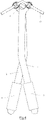
- the figure 1 represents a non-limiting embodiment of a bender according to the invention. It consists of an upper arm (1) and a lower arm (2) articulated by an axis of rotation (3) also supporting a main roller (4).
- Each of the arms (1, 2) consists of a bending head (5, 6) and a handle (7, 8).
- the arms (1, 2) are cut from a metal plate with a thickness of 3 millimeters. They can also be made by molding a plastic material filled with carbon fibers or glass fibers.
- the median surfaces of these arms (1, 2) are parallel and flat so as to allow the sliding of one arm over the other, over the entire authorized movement.
- the arms have a substantially constant width, of sixteen millimeters for example, for metal arms, made of steel.
- the handle (7, 8) of the arms (1, 2) is sheathed in its rear part to facilitate gripping.
- the thickness of the sheathing is determined so as not to interfere with the superimposition of the arms. Where applicable, the sheathing does not extend over the facing surfaces of the arms (1, 2).
- the handle (7, 8) has a divergent shape, with a rear part (9, 10) forming an angle of approximately 160° with the front part (11, 12).
- the length of the rear part (9, 10) is about 150 millimeters, and the length of the front part (11, 12) is about 100 millimeters.
- the length of the rear part (9, 10) corresponds substantially to 1.5 times length of the front part (11, 12).
- the opening of the rear part (9, 10) is approximately 100 millimeters, for a good grip of the instrument. It is thus possible to perform an action with one hand.
- the short parts (5, 6) of the arms (1, 2) have a length of approximately 25 millimeters. They each support an eyelet (13, 14) rotatable with respect to an axis parallel to the axis of rotation (3) of the main roller (4).
- each eyelet (13, 14) consists of a cylindrical part extended at one of its ends by a flat head (130, 140) with a section smaller than the section of said part.
- the head (130, 140) is traversed by a diametral slot (15, 16) of a section slightly greater than that of the rod to be bent.
- the section of the diametral slot (15, 16) is 6 millimeters for rods to be bent with a section of 5.5 millimeters. The play not only makes it possible to easily introduce the rod, but also to move it and withdraw it notwithstanding the deformations applied during bending.
- the cylindrical part is mounted through a bore made at the end of the short part (5, 6) of the associated arm (1, 2) and having an axis parallel to the axis of the main roller (4) . It has a section slightly smaller than that of the bore so as to leave a clearance allowing rotation of the eyelet in the bore.
- each eyelet (13, 14) is arranged to have an axis perpendicular to the axis of rotation of the eyelet. Because the eyelets (13, 14) are mounted free to rotate on the arms, the axis of the slots (15, 16) remains substantially perpendicular to the axis of the rod (19) during the centering operation. Thus, during the bending operation, the rod, under the action of the bending force applied by the main roller (4), will slide axially inside the slots.
- each eyelet (13, 14) is shaped and arranged relative to the main roller (4) to present, when the head (130, 140) of each eyelet is positioned to present the light (15, 16 ) associated opposite the main roller (4), a spacing allowing the passage of the rod (19) between the main roller (4) and the eyelets (13, 14).
- the outer periphery of each head (130, 140) extending in a plane perpendicular to the axis of the slots (12, 14) then constitutes a support zone allowing, with the main roller (4), the bending of the stem.
- the bearing surface of each head (130, 140) is provided with a groove of a radius substantially equal to that of the rod to be bent.
- each eyelet has at least one plane support zone, the remaining zone being circular.
- the eyelet offers two distinct bending radii of the rod. It is of course obvious that the number of support zones is not limited to one or two, and that a perimeter may be provided offering more than two distinct zones depending on the number of bending radii desired.
- the angle formed between the straight line passing between the axis of rotation of one of the eyelets and the axis of rotation of the main roller on the one hand, and the axis passing between the axis of rotation of a main roller and the grip zone of the corresponding arm on the other hand, is approximately 90°.
- the main roller (3) as well as the eyelets (13, 14) are fixed by nuts. These nuts may be removable to allow replacement of the eyelets, in particular to adapt to the size of the rods to be bent.
- the eyelet (14) mounted on the lower arm (2) has a base (17) of a thickness substantially equal to that of the arm (2).
- the main roller (3) is optionally free to rotate. It has a groove (18) whose radius of curvature is 2.8 millimeters, substantially identical or even slightly greater than that of the rod to be bent.
- this distance is 18 millimeters.
- the picture 3 represents a view of the bender at the start of bending.
- the intervertebral connecting rod (19) is slid into the two slots of the eyelets and slides into the groove of the main roller (4).
- the two arms are separated sufficiently to free a path for the passage of the rod (19).
- the sleeves (7, 8) By bringing the sleeves (7, 8) closer to the two arms (1, 2), a constraint is exerted via the two eyelets and the main roller, with a significant leverage effect, causing the rod to be bent (19) to deform.
- the amplification of the forces is approximately 12 times.
- the level of amplification is determined by the ratio between the length of the rear part (9, 10) calculated between the point of articulation supporting the axis of rotation (3) of the main roller, and the length of the short part (5, 6) calculated between this point of articulation supporting the axis of rotation (3) of the main roller (4) and the axis of rotation of the eyelet (13, 14) supported by the arm.
- the figure 4 represents the situation where one seeks a particularly weak radius of curvature.
- the configuration of the sleeves (7, 8) allows a large movement, exceeding the position in which the arms are parallel.
- the arms can cross, which increases the amplitude of the travel.
- the figure 5 represents the situation where the rod (19) is the subject of a succession of centerings by regular movements of the rod. A first bending is performed, then the rod is moved longitudinally with respect to the eyelets and the roller by a few millimeters before performing a new bending step, and so on.
- the figures 6 and 7 relate to a variant of the invention, representing respectively a front three-quarter view of a bender according to the invention and a perspective view of the head of an arm according to this variant.
- the arms (1, 2) are not constituted by flat metal elements, but by molded elements with a substantially rectangular section.
- the rectangular section is determined to present a width (measured in a plane parallel to the median plane of the instrument) greater than thickness (measured along an axis parallel to the axis of rotation of the main roller).
- the arms can be made of a filled polymer for single-use surgical instrument applications.
- the two arms (1, 2) are identical. This characteristic is however not necessary, it would be possible to produce an instrument with two different and complementary arms. This characteristic is however preferred because it makes it possible to reduce the cost of manufacture, by the use of a single common mold for the right arm and the left arm, and moreover it leads to very solid and reliable constructions from the point of view. mechanical.
- Each of the arms (1, 2) has, as in the first variant, a rear part (9, 10), the rear segment of which forms the sleeves (7, 8) respectively.
- These sleeves (7, 8) diverge slightly outwards, with an angle of approximately 15° relative to the front segment (11, 12), comprised between the axis of rotation (3) and the handle.
- These sleeves (7, 8) have a greater thickness than the front segment (11, 12) in order to improve the comfort of use and to reinforce the lever arm subjected to significant forces during bending.
- the thickness of the handle (7, 8) is about 15 millimeters, while the thickness of the front segment (11, 12) is 10 millimeters.
- the handle (7, 8) can have an ergonomic shape adapted to the hand of a user, for example a shape of a handle with fluted recesses.
- Each head (5, 6) has in the example described a triangular shape extending outwards.
- This triangular zone supports at its end crossed by the axis of rotation of the eyelet (13, 14), respectively, a vertical extension (20, 21), coaxial with the said axis of rotation, of a height corresponding to the thickness of the head (6, 5) of the complementary arm.
- the head (5, 6) further comprises a radial extension (22, 23), extending parallel to the triangular zone, between the axis of rotation of the eyelet (13, 14) and the axis of rotation ( 3) of the main roller.
- the radial extension (22, 23) and the triangular zone of the head (5, 6) form a fork making it possible to receive the triangular zone of the complementary head (6, 5) to form a hinge.
- the vertical extension (20), the radial extension (22) and the triangular zone can be made monolithically by molding a single piece forming a molded arm in filled polymer.
- the arm by assembling three separate parts, namely a radial extension consisting of a ring of a thickness corresponding to that of the triangular zone, and a radial extension consisting of a rectangular part having two recesses for the passage of the axes of the eyelet on the one hand and of the main roller on the other.
- the axes also ensure the assembly of the three constituent parts of the head.
- At least one of the handles (7, 8) of any of the variants has markings (24) making it possible to inform the user of the angle of curvature reached.
- the reading is done at the level of the intersection of the two arms.
- the mark visible at the intersection gives an indication of the level of curvature reached.
- the value of each of the graduations is determined by a geometric calculation taking into account the dimensions of the arm, rollers and eyelets. It can also be determined empirically, by proceeding successively to bending the rod, the radius of curvature of which is measured after releasing the force, and the bridge of intersection is noted at the time of the maximum force, to assign it the value of the radius of curvature observed.
Landscapes
- Health & Medical Sciences (AREA)
- Engineering & Computer Science (AREA)
- Orthopedic Medicine & Surgery (AREA)
- Surgery (AREA)
- Life Sciences & Earth Sciences (AREA)
- Mechanical Engineering (AREA)
- Medical Informatics (AREA)
- Heart & Thoracic Surgery (AREA)
- Biomedical Technology (AREA)
- Molecular Biology (AREA)
- Animal Behavior & Ethology (AREA)
- General Health & Medical Sciences (AREA)
- Public Health (AREA)
- Veterinary Medicine (AREA)
- Nuclear Medicine, Radiotherapy & Molecular Imaging (AREA)
- Prostheses (AREA)
- Bending Of Plates, Rods, And Pipes (AREA)
- Transmission Devices (AREA)
- Orthopedics, Nursing, And Contraception (AREA)
Description
- La présente invention concerne le domaine des outils de cintrage manuel de tiges, notamment pour le cintrage de tiges orthopédiques telles que des éléments de liaison intervertébraux.
- Ces tiges sont typiquement des tiges en acier ou en titane, d'une section de cinq à six millimètres. Les rayons de cintrage recherchés sont habituellement compris entre vingt à cent millimètres. Le cintrage nécessite l'exercice d'un effort très important de plusieurs milliers de Newton, notamment pour les tiges en titane.
- On connaît dans l'état de la technique plusieurs brevets décrivant des outils de cintrage manuels constitués de deux bras articulés supportant un galet principal et deux galets secondaires montés chacun à l'extrémité de l'un des deux bras. De tels outils sont décrits dans les brevets américains
US3824834 ,US4474046 ,US5490409 ouUS5819580 . - Ces brevets proposent l'utilisation d'un galet principal ajustable pour optimiser l'angle de cintrage de la tige.
- Ces outils de cintrage manuel présentent plusieurs inconvénients.
- En premier lieu, la mise en œuvre des outils de cintrage connu constitue un exercice physique important, peu compatible avec une manipulation précautionneuse et précise : l'opérateur doit exercer sur les branches un effort à la limite de ses forces, ce qui l'oblige à concentrer son attention à l'exercice de ces efforts, plutôt qu'au positionnement précis de la tige à cintrer et à la vérification permanente du maintien d'un positionnement correct. Lorsque l'effort est relâché, il arrive que la tige sorte de la tête de l'outil et choit, ce qui est particulièrement problématique lorsqu'il s'agit de tiges orthopédiques nécessitant impérativement la préservation de la stérilité.
- Un deuxième problème est celui des limites de l'angle de cintrage. Les outils de l'art antérieur ne permettent pas des cintrages avec des rayons de courbure très faibles, et sont généralement limités à des rayons de courbure supérieure à une cinquantaine de millimètres.
- Un troisième problème est celui du poids et le nettoyage de ces outils. Afin de résister aux efforts importants appliqués par l'utilisateur, il s'agit généralement d'outils présentant des bras métalliques massifs, et des articulations présentant des zones d'accumulation de salissures.
- Afin de remédier à ces problèmes, l'invention concerne selon son acception la plus générale une cintreuse à came constituée par deux bras articulés, comportant un galet principal coaxial avec l'axe d'articulation desdits bras, l'extrémité de chacun desdits bras présentant des moyens pour exercer un effort de cintrage sur une tige caractérisé en ce que lesdits moyens sont constitués par des œillets fermés, chacun desdits œillets étant monté à l'extrémité de la partie courte de l'un desdits bras de manière mobiles en rotation par rapport à un axe parallèle à l'axe dudit galet principal.
- On entend par « partie courte » du bras, la partie s'étendant en avant du point d'articulation. Le point d'articulation se trouve entre une partie courte supportant les œillets et une partie longue servant à exercer une force, et formant levier amplificateur d'effort.
- Avantageusement, chaque œillet comporte une lumière d'axe perpendiculaire à l'axe de rotation de l'œillet, la lumière étant agencée pour permettre le passage de la tige à cintrer.
- Selon un mode de réalisation particulier, chaque œillet est constitué par une pièce cylindrique pourvue en extrémité d'une tête traversée par une lumière, ladite pièce étant montée libre en rotation au travers d'un alésage ménagé à l'extrémité de la partie courte (5, 6) desdits bras. Ainsi configurés, les œillets assurent un guidage axial de la tige au cours de l'opération de cintrage permettant un cintrage de la tige important et uniforme.
- De préférence, les deux bras sont superposés.
- Avantageusement, l'œillet monté sur le bras inférieur présente une embase d'une épaisseur correspondant à l'épaisseur du bras supérieur, afin que les centres des lumières des deux œillets soient coplanaires.
- Selon une autre variante avantageuse, les deux bras sont plats, et sont orientés parallèlement au plan médian.
- De préférence, l'angle formé entre la droite passant entre l'axe de rotation de l'un des œillets et l'axe de rotation du galet principal d'une part, et l'axe passant entre l'axe de rotation d'un galet principal et la zone de préhension du bras correspondant d'autre part, est compris entre 75° et 100°, de préférence d'environ 90°
- Avantageusement, la partie du bras opposée à l'œillet forme un angle divergent, c'est-à-dire que le segment arrière du bras n'est pas dans le prolongement du segment principal du manche, mais dévie vers l'extérieur.
- Selon une variante, le galet principal présente une gorge d'un rayon sensiblement égal à celui de la tige à cintrer, dont le centre est coplanaire avec le centre des lumières formées dans les œillets.
- Selon un mode de réalisation préféré, les bras sont configurés pour permettre le croisement de leurs zones intermédiaires.
- Selon un mode de réalisation particulier, les bras sont réalisés en un polymère, de préférence stérile, pour la réalisation d'un outil à usage unique.
- Selon une variante de réalisation, chaque tête supporte à son extrémité traversée par l'axe de rotation de l'œillet un prolongement vertical, coaxial avec ledit axe de rotation, d'une hauteur correspondant à l'épaisseur de la tête du bras complémentaire, ladite tête comprenant en outre un prolongement radial, s'étendant parallèlement à la zone triangulaire, entre l'axe de rotation de l'œillet et l'axe de rotation du galet principal pour former une fourchette permettant de recevoir la zone triangulaire de la tête complémentaire pour former une charnière.
- Avantageusement, le prolongement vertical, le prolongement radial et la tête sont réalisés de manière monolithique par moulage d'une pièce unique.
- Selon une alternative, ladite tête présente une forme triangulaire s'étendant vers l'extérieur.
- Selon une autre variante, l'un au moins des manches présente des marquages représentatifs du rayon de courbure atteint.
- D'autres objets et avantages de l'invention apparaîtront au cours de la description qui suit, faite en référence aux dessins annexés, concernant un exemple non limitatif de réalisation d'une cintreuse selon l'invention, dans lesquels :
- la
figure 1 représente une vue d'une cintreuse en position neutre - la
figure 2 représente une vue de face de la tête de la cintreuse selon l'invention - la
figure 3 représente une vue de ladite cintreuse, avec une tige en début de cintrage - la
figure 4 représente une vue de ladite cintreuse, avec une tige en fin de cintrage - la
figure 5 représente une vue de ladite cintreuse, avec une tige ayant subi une succession de cintrages - la
figure 6 représente une vue de trois quart avant d'une variante de réalisation d'une cintreuse selon l'invention - la
figure 7 représente une vue en perspective de la tête d'un bras selon cette variante. - La
figure 1 représente un exemple non limitatif de réalisation d'une cintreuse selon l'invention. Elle est constituée par un bras supérieur (1) et un bras inférieur (2) articulés par un axe de rotation (3) supportant également un galet principal (4). - Chacun des bras (1, 2) est constitué par une tête (5, 6) de cintrage et un manche (7, 8). Les bras (1, 2) sont découpés dans une plaque métallique d'une épaisseur de 3 millimètres. Ils peuvent également être réalisés par moulage d'une matière plastique chargé de fibres de carbone ou de fibres de verre. Les surfaces médianes de ces bras (1, 2) sont parallèles et planes de façon à permettre le glissement d'un bras sur l'autre, sur l'ensemble du débattement autorisé.
- Les bras présentent une largeur sensiblement constante, de seize millimètres par exemple, pour des bras métalliques, en acier.
- Le manche (7, 8) des bras (1, 2) est gainé dans sa partie arrière pour faciliter la préhension. L'épaisseur du gainage est déterminée pour ne pas gêner la superposition des bras. Le cas échéant, le gainage ne s'étend pas sur les surfaces en regard des bras (1, 2).
- Le manche (7, 8) présente une forme divergente, avec une partie arrière (9, 10) formant un angle d'environ 160° avec la partie avant (11, 12).
- La longueur de la partie arrière (9, 10) est d'environ 150 millimètres, et la longueur de la partie avant (11, 12) est d'environ 100 millimètres. La longueur de la partie arrière (9, 10) correspond sensiblement à 1,5 fois longueur de la partie avant (11, 12).
- En début de cintrage, correspondant à la phase où les efforts à exercer son maximum, l'ouverture de la partie arrière (9, 10) est d'environ 100 millimètres, pour une bonne préhension de l'instrument. Il est ainsi possible d'exercer une action avec une seule main.
- Les parties courtes (5, 6) des bras (1, 2) présentent une longueur d'environ 25 millimètres. Elles supportent chacune un œillet (13, 14) rotatif par rapport à un axe parallèle à l'axe de rotation (3) du galet principal (4).
- Dans le mode de réalisation illustré, chaque œillet (13, 14) est constitué par une pièce cylindrique prolongée à l'une de ses extrémités par une tête (130, 140) plate de section inférieure à la section de ladite pièce. La tête (130, 140) est traversée par une lumière diamétrale (15, 16) d'une section légèrement supérieure à celle de la tige à cintrer. A titre d'exemple, la section de la lumière diamétrale (15, 16) est de 6 millimètres pour des tiges à cintrer d'une section de 5,5 millimètres. Le jeu permet non seulement d'introduire facilement la tige, mais aussi de la déplacer et de la retirer nonobstant les déformations appliquées lors du cintrage. La pièce cylindrique est montée au travers d'un alésage ménagé au niveau de l'extrémité de la partie courte (5, 6) du bras associé (1, 2) et présentant un axe parallèle à l'axe du galet principal (4). Elle présente une section légèrement inférieure à celle de l'alésage de manière à laisser un jeu permettant la rotation de l'œillet dans l'alésage.
- Avantageusement, la lumière (15, 16) de chaque œillet (13, 14) est agencée pour présenter un axe perpendiculaire à l'axe de rotation de l'oeillet. Du fait que les oeillets (13, 14) sont montés libres en rotation sur les bras, l'axe des lumières (15, 16) reste sensiblement perpendiculaire à l'axe de la tige (19) durant l'opération de centrage. Ainsi, durant l'opération de cintrage, la tige, sous l'action de l'effort de cintrage appliqué par le galet principal (4), va coulisser axialement à l'intérieur des lumières.
- Selon un mode de réalisation particulier, chaque œillet (13, 14) est conformé et agencé par rapport au galet principal (4) pour présenter, lorsque la tête (130, 140) de chaque oeillet est positionnée pour présenter la lumière (15, 16) associée en regard du galet principal (4), un écartement permettant le passage de la tige (19) entre le galet principal (4) et les oeillets (13, 14). Le pourtour extérieur de chaque tête (130, 140) s'étendant dans un plan perpendiculaire à l'axe des lumières (12, 14) constitue alors une zone d'appui permettant, avec le galet principal (4), le cintrage de la tige. Avantageusement, la surface d'appui de chaque tête (130, 140) est pourvue d'une gorge de rayon sensiblement égal à celui de la tige à cintrer. Selon une configuration avantageuse, le pourtour extérieur de chaque œillet présente au moins une zone d'appui plane, la zone restante étant circulaire. Pourvu ainsi de deux zones distinctes, l'œillet offre deux rayons de cintrage distincts de la tige. Il est bien entendu évident que le nombre de zones d'appui ne se limite pas à un ou deux, et qu'il peut être prévu un pourtour offrant plus de deux zones distinctes selon le nombre de rayons de cintrage souhaité.
- L'angle formé entre la droite passant entre l'axe de rotation de l'un des œillets et l'axe de rotation du galet principal d'une part, et l'axe passant entre l'axe de rotation d'un galet principal et la zone de préhension du bras correspondant d'autre part, est d'environ 90°.
- Le galet principal (3) ainsi que les œillets (13, 14) sont fixés par des écrous. Ces écrous sont éventuellement démontables pour permettre le remplacement des œillets, notamment pour adapter à la taille des tiges à cintrer.
- Comme représenté en
figure 2 , afin de rattraper le décalage résultant de l'épaisseur des bras, l'œillet (14) monté sur le bras inférieur (2) présente une embase (17) d'une épaisseur sensiblement égale à celle du bras (2). - Le galet principal (3) est optionnellement libre en rotation. Il présente une gorge (18) dont le rayon de courbure est de 2,8 millimètres, sensiblement identique voire légèrement supérieur à celui de la tige à cintrer.
- La distance entre l'axe (3) du galet principal d'une part, et l'axe de chacun des œillets d'autre part, et minimal et limité par la section de l'œillet et du galet principal, et le cas échéant de l'embase de l'œillet (17) et éventuellement des écrous. Dans l'exemple décrit, cette distance est de 18 millimètres.
- La
figure 3 représente une vue de la cintreuse en début de cintrage. la tige de liaison intervertébrale (19) est glissée dans les deux lumières des œillets et glisse dans la gorge du galet principal (4). Les deux bras sont écartés suffisamment pour libérer un chemin de passage de la tige (19). - A partir de ce moment, la tige de liaison (19) est maintenue en place, et ne peut tomber même en cas de manipulation maladroite de la cintreuse (sauf dans la situation très improbable d'une orientation verticale de l'outil dans une configuration où les deux lumières sont alignés verticalement et où aucun effort n'est exercé sur les bras).
- En rapprochant les manches (7, 8) des deux bras (1, 2), on exerce une contrainte par l'intermédiaire des deux œillets et du galet principal, avec un effet de levier important, provoquant la déformation de la tige à cintrer (19). Dans l'exemple décrit, l'amplification des efforts est environ de 12 fois.
- Le niveau d'amplification est déterminé par le rapport entre la longueur partie arrière (9, 10) calculée entre le point d'articulation supportant l'axe de rotation (3) du galet principal, et la longueur de la parties courtes (5, 6) calculée entre ce point d'articulation supportant l'axe de rotation (3) du galet principal (4) et l'axe de rotation de l'œillet (13, 14) supporté par le bras.
- La
figure 4 représente la situation où on cherche un rayon de courbure particulièrement faible. La configuration des manches (7, 8) permet un débattement important, dépassant la position dans laquelle les bras sont parallèles. Les bras peuvent se croiser, ce qui permet d'augmenter l'amplitude du débattement. - La
figure 5 représente la situation où la tige (19) fait l'objet d'une succession de centrages par déplacements régulier de la tige. On exerce un premier cintrage, puis on déplace longitudinalement la tige par rapport aux œillets et au galet de quelques millimètres avant d'exercer une nouvelle étape de cintrage, et ainsi de suite. - Les
figures 6 et 7 concernent une variante de l'invention, représentant respectivement une vue de trois-quart avant d'une cintreuse selon l'invention et une vue en perspective de la tête d'un bras selon cette variante. - Dans cette réalisation, les bras (1, 2) ne sont pas constitués par des éléments plats métalliques, mais par des éléments moulés à section sensiblement rectangulaire. La section rectangulaire est déterminée pour présenter une largeur (mesurée dans un plan parallèle au plan médian de l'instrument) supérieure à l'épaisseur (mesurée selon un axe parallèle à l'axe de rotation du galet principal). Les bras peuvent être réalisés en un polymère chargé pour des applications d'instruments chirurgicaux à usage unique.
- Comme dans la variante précédente, les deux bras (1, 2) sont identiques. Cette caractéristique n'est toutefois pas nécessaire, il serait possible de réaliser un instrument avec deux bras différents et complémentaires. Cette caractéristique est toutefois préférée car elle permet de réduire le coût de fabrication, par l'utilisation d'un seul moule commun pour le bras droit et le bras gauche, et de surcroit elle aboutit à des constructions très solides et fiables du point de vue mécanique.
- Chacun des bras (1, 2) présente comme dans la première variante une partie arrière (9, 10) dont le segment arrière forme les manches respectivement (7, 8). Ces manches (7, 8) sont légèrement divergent vers l'extérieur, avec un angle d'environ 15° par rapport au segment avant (11, 12), compris entre l'axe de rotation (3) et le manche. Ces manches (7, 8) présentent une épaisseur supérieure au segment avant (11, 12) afin d'améliorer le confort d'utilisation et renforcer le bras de levier soumis à des efforts importants lors du cintrage. L'épaisseur du manche (7, 8) est d'environ 15 millimètres, alors que l'épaisseur du segment avant (11, 12) est de 10 millimètres. Le manche (7, 8) peut présenter une forme ergonomique adaptée à la main d'un utilisateur, par exemple une forme de poignée avec des évidements cannelés.
- Chaque tête (5, 6) présente dans l'exemple décrit une forme triangulaire s'étendant vers l'extérieur. Cette zone triangulaire supporte à son extrémité traversée par l'axe de rotation de l'œillet respectivement (13, 14) un prolongement vertical (20, 21), coaxial avec ledit axe de rotation, d'une hauteur correspondant à l'épaisseur de la tête (6, 5) du bras complémentaire.
- La tête (5, 6) comprend en outre un prolongement radial (22, 23), s'étendant parallèlement à la zone triangulaire, entre l'axe de rotation de l'œillet (13, 14) et l'axe de rotation (3) du galet principal.
- Le prolongement radial (22, 23) et la zone triangulaire de la tête (5, 6) forme une fourchette permettant de recevoir la zone triangulaire de la tête complémentaire (6, 5) pour former une charnière.
- Le prolongement vertical (20), le prolongement radial (22) et la zone triangulaire peuvent être réalisés de manière monolithique par moulage d'une pièce unique formant un bras moulé en polymère chargé.
- Il est aussi possible de réaliser le bras par assemblage de trois pièces distincts, à savoir un prolongement radial constitué par une bague d'une épaisseur correspondant à celle de la zone triangulaire, et un prolongement radial constitué par une pièce rectangulaire présentant deux évidements pour le passage des axes de l'œillet d'une part et du galet principal d'autre part. Dans ce cas, les axes assurent également l'assemblage des trois pièces constitutives de la tête.
- Optionnellement l'un au moins des manches (7, 8) de l'une quelconque des variantes (et de préférence le bras inférieur) présente des marquages (24) permettant d'informer l'utilisateur de l'angle de courbure atteinte. La lecture se fait au niveau de l'intersection des deux bras. Le repère visible à l'intersection donne une indication sur le niveau de courbure atteint. La valeur de chacune des graduations est déterminée par un calcul géométrique prenant en compte les dimensions du bras, des galets et œillets. Elle peut également être déterminée de manière empirique, en procédant successivement à des cintrages de tige dont on mesure le rayon de courbure après relâchement de l'effort, et on note le pont d'intersection au moment de l'effort maximum, pour lui attribuer la valeur du rayon de courbure observé.
Claims (15)
- Cintreuse à came constituée par deux bras (1, 2) montés articulés l'un par rapport à l'autre autour d'un axe d'articulation, chaque bras comprenant une partie courte (5, 6) s'étendant en avant de l'axe d'articulation, chaque partie courte (5,6) présentant en extrémité des moyens pour exercer un effort de cintrage sur une tige (19), la cintreuse comportant en outre un galet principal(4) coaxial avec l'axe d'articulation (3) desdits bras (1,2), caractérisée en ce que les moyens pour exercer un effort de cintrage sont constitués par deux œillets (13, 14) montés respectivement mobiles en rotation sur l'extrémité de la partie courte (5, 6) de chacun desdits bras (1, 2) autour d'un axe de rotation parallèle à l'axe dudit galet principal (4), chaque œillet (13, 14) comportant une lumière (15, 16) d'axe perpendiculaire à l'axe de rotation de l'œillet, la lumière étant agencée pour permettre le passage de la tige (19) à cintrer.
- Cintreuse selon la revendication 1, caractérisée en ce que chaque œillet (13, 14) est constitué par une pièce cylindrique pourvue en extrémité d'une tête traversée par une lumière (15, 16), ladite pièce étant montée libre en rotation au travers d'un alésage ménagé à l'extrémité de la partie courte (5, 6) desdits bras (1, 2).
- Cintreuse selon la revendication 1 ou la revendication 2, caractérisée en ce que les deux bras (1, 2) sont superposés.
- Cintreuse selon la revendication 3, caractérisée en ce que l'œillet monté sur le bras inférieur présente une embase (17) d'une épaisseur correspondant à l'épaisseur du bras supérieur, afin que les centres des lumières des deux œillets soient coplanaires.
- Cintreuse selon l'une au moins des revendications précédentes, caractérisée en ce que les deux bras (1, 2) sont plats, et sont orientés parallèlement au plan médian.
- Cintreuse selon l'une au moins des revendications précédentes, caractérisée en ce que l'angle formé entre la droite passant entre l'axe de rotation de l'un des œillets (13, 14) et l'axe de rotation (4) du galet principal d'une part, et l'axe passant entre l'axe de rotation d'un galet principal et la zone de préhension du bras correspondant d'autre part, est compris entre 75° et 100°.
- Cintreuse selon l'une au moins des revendications précédentes, caractérisée en ce que l'angle formé entre la droite passant entre l'axe de rotation de l'un des œillets et l'axe de rotation du galet principal d'une part, et l'axe passant entre l'axe de rotation d'un galet principal et la zone de préhension du bras correspondant d'autre part, est de 90°.
- Cintreuse selon l'une au moins des revendications précédentes, caractérisée en ce que chaque bras comporte une partie opposée à la partie courte portant l'œillet présentant un segment avant et un segment arrière divergent par rapport au segment avant vers l'extérieur.
- Cintreuse selon l'une au moins des revendications précédentes, caractérisée en ce le galet principal (4) présente une gorge d'un rayon sensiblement égal à celui de la tige à cintrer, dont le centre est coplanaire avec le centre des lumières formées dans les œillets (13, 14).
- Cintreuse selon l'une au moins des revendications précédentes, caractérisée en ce que les bras sont configurés pour permettre le croisement de zones intermédiaires desdits bras.
- Cintreuse selon l'une au moins des revendications précédentes, caractérisée en ce que chaque partie courte (5, 6) supporte à son extrémité traversée par l'axe de rotation de l'œillet (13, 14) un prolongement vertical (20, 21), coaxial avec ledit axe de rotation, d'une hauteur correspondant à l'épaisseur de la partie courte (6, 5) du bras complémentaire, ladite partie courte (5, 6) comprenant en outre un prolongement radial (22, 23), s'étendant parallèlement à la zone triangulaire, entre l'axe de rotation de l'œillet (13, 14) et l'axe de rotation (3) du galet principal pour former une fourchette permettant de recevoir la zone triangulaire de la partie courte complémentaire (6, 5) pour former une charnière.
- Cintreuse selon la revendication précédente, caractérisée en ce que le prolongement vertical (20), le prolongement radial (22) et la partie courte (5) sont réalisée de manière monolithique par moulage d'une pièce unique.
- Cintreuse selon l'une au moins des revendications précédentes, caractérisée en ce que ladite partie courte (5, 6) présente une forme triangulaire s'étendant vers l'extérieur.
- Cintreuse selon l'une au moins des revendications précédentes, caractérisée en ce que chaque bras comporte un manche (7, 8), l'un au moins desdits manches (7, 8) présentant des marquages (24) représentatifs du rayon de courbure atteint.
- Cintreuse selon l'une au moins des revendications précédentes, caractérisée en ce que les bras sont réalisés par moulage en polymère.
Priority Applications (1)
| Application Number | Priority Date | Filing Date | Title |
|---|---|---|---|
| HRP20221091TT HRP20221091T1 (hr) | 2012-04-02 | 2013-04-02 | Stroj za savijanje s grebenom, namijenjen za ortopedsku šipku |
Applications Claiming Priority (2)
| Application Number | Priority Date | Filing Date | Title |
|---|---|---|---|
| FR1252995A FR2988583B1 (fr) | 2012-04-02 | 2012-04-02 | Cintreuse a came |
| PCT/FR2013/050721 WO2013150233A1 (fr) | 2012-04-02 | 2013-04-02 | Cintreuse à came pour tige orthopédique |
Publications (2)
| Publication Number | Publication Date |
|---|---|
| EP2833814A1 EP2833814A1 (fr) | 2015-02-11 |
| EP2833814B1 true EP2833814B1 (fr) | 2022-06-08 |
Family
ID=48237115
Family Applications (1)
| Application Number | Title | Priority Date | Filing Date |
|---|---|---|---|
| EP13719965.9A Active EP2833814B1 (fr) | 2012-04-02 | 2013-04-02 | Cintreuse à came pour tige orthopédique |
Country Status (8)
| Country | Link |
|---|---|
| US (1) | US9186195B2 (fr) |
| EP (1) | EP2833814B1 (fr) |
| ES (1) | ES2927173T3 (fr) |
| FR (1) | FR2988583B1 (fr) |
| HR (1) | HRP20221091T1 (fr) |
| PL (1) | PL2833814T3 (fr) |
| PT (1) | PT2833814T (fr) |
| WO (1) | WO2013150233A1 (fr) |
Families Citing this family (32)
| Publication number | Priority date | Publication date | Assignee | Title |
|---|---|---|---|---|
| US10758283B2 (en) | 2016-08-11 | 2020-09-01 | Mighty Oak Medical, Inc. | Fixation devices having fenestrations and methods for using the same |
| US8549888B2 (en) | 2008-04-04 | 2013-10-08 | Nuvasive, Inc. | System and device for designing and forming a surgical implant |
| US12357413B2 (en) | 2010-06-29 | 2025-07-15 | Mighty Oak Medical, Inc. | Patient-matched apparatus for use in spine related surgical procedures and methods for using the same |
| US11039889B2 (en) | 2010-06-29 | 2021-06-22 | Mighty Oak Medical, Inc. | Patient-matched apparatus and methods for performing surgical procedures |
| US9642633B2 (en) | 2010-06-29 | 2017-05-09 | Mighty Oak Medical, Inc. | Patient-matched apparatus and methods for performing surgical procedures |
| US11806197B2 (en) | 2010-06-29 | 2023-11-07 | Mighty Oak Medical, Inc. | Patient-matched apparatus for use in spine related surgical procedures and methods for using the same |
| WO2017066518A1 (fr) | 2010-06-29 | 2017-04-20 | Mighty Oak Medical, Inc. | Appareil de mise en correspondance de patients et procédés d'exécution de procédures chirurgicales |
| US11376073B2 (en) | 2010-06-29 | 2022-07-05 | Mighty Oak Medical Inc. | Patient-matched apparatus and methods for performing surgical procedures |
| US11207132B2 (en) | 2012-03-12 | 2021-12-28 | Nuvasive, Inc. | Systems and methods for performing spinal surgery |
| US9968408B1 (en) | 2013-03-15 | 2018-05-15 | Nuvasive, Inc. | Spinal balance assessment |
| EP2810611B1 (fr) * | 2013-06-06 | 2017-03-08 | Stryker European Holdings I, LLC | Instrument de pliage pour élément chirurgical |
| WO2015054543A1 (fr) | 2013-10-09 | 2015-04-16 | Nuvasive, Inc. | Correction chirurgicale de la colonne vertébrale |
| US9848922B2 (en) | 2013-10-09 | 2017-12-26 | Nuvasive, Inc. | Systems and methods for performing spine surgery |
| US10709509B2 (en) | 2014-06-17 | 2020-07-14 | Nuvasive, Inc. | Systems and methods for planning, performing, and assessing spinal correction during surgery |
| US9913669B1 (en) | 2014-10-17 | 2018-03-13 | Nuvasive, Inc. | Systems and methods for performing spine surgery |
| US10695099B2 (en) | 2015-02-13 | 2020-06-30 | Nuvasive, Inc. | Systems and methods for planning, performing, and assessing spinal correction during surgery |
| CN105030322B (zh) * | 2015-08-26 | 2017-07-28 | 王亭 | 医用弯棒器 |
| US10463433B2 (en) | 2016-03-02 | 2019-11-05 | Nuvasive, Inc. | Systems and methods for spinal correction surgical planning |
| US10610277B2 (en) * | 2016-03-31 | 2020-04-07 | K2M, Inc. | Surgical rod bender |
| US12016573B2 (en) | 2016-08-11 | 2024-06-25 | Mighty Oak Medical, Inc. | Drill apparatus and surgical fixation devices and methods for using the same |
| US10743890B2 (en) | 2016-08-11 | 2020-08-18 | Mighty Oak Medical, Inc. | Drill apparatus and surgical fixation devices and methods for using the same |
| USD858765S1 (en) | 2017-10-26 | 2019-09-03 | Mighty Oak Medical, Inc. | Cortical surgical guide |
| USD857893S1 (en) | 2017-10-26 | 2019-08-27 | Mighty Oak Medical, Inc. | Cortical surgical guide |
| USD895111S1 (en) | 2018-06-04 | 2020-09-01 | Mighty Oak Medical, Inc. | Sacro-iliac guide |
| USD948717S1 (en) | 2018-06-04 | 2022-04-12 | Mighty Oak Medical, Inc. | Sacro-iliac guide |
| EP3946128A4 (fr) | 2019-03-26 | 2022-11-23 | Mighty Oak Medical, Inc. | Appareil adapté à un patient destiné à être utilisé dans des procédures chirurgicales assistées par réalité augmentée et procédés d'utilisation de celui-ci |
| US11583322B2 (en) * | 2021-02-09 | 2023-02-21 | Warsaw Orthopedic, Inc. | Dual-sided rod bender |
| US12207857B2 (en) | 2021-06-08 | 2025-01-28 | Medos International Sàrl | Ratchet rod bender and related methods |
| USD992114S1 (en) | 2021-08-12 | 2023-07-11 | Mighty Oak Medical, Inc. | Surgical guide |
| US12636167B2 (en) | 2023-02-21 | 2026-05-26 | Mighty Oak Medical, Inc. | Interbody device incorporating lattice structure and related systems and methods |
| US12440276B2 (en) | 2023-03-14 | 2025-10-14 | Mighty Oak Medical, Inc. | Systems and methods for presurgical planning |
| CN119097407B (zh) * | 2024-10-15 | 2025-07-22 | 浙江德康医疗器械有限公司 | 一种大角度定量折弯弯棒器 |
Citations (1)
| Publication number | Priority date | Publication date | Assignee | Title |
|---|---|---|---|---|
| US4474046A (en) * | 1982-06-18 | 1984-10-02 | Zimmer, Inc. | Rod bender |
Family Cites Families (10)
| Publication number | Priority date | Publication date | Assignee | Title |
|---|---|---|---|---|
| FR1342386A (fr) * | 1962-10-19 | 1963-11-08 | Ridge Tool Co | Appareil à cintrer les tubes |
| US3824834A (en) * | 1973-03-05 | 1974-07-23 | H Durham | Cable bender |
| US4389872B1 (en) * | 1981-01-30 | 1995-04-11 | Pullman Co | Tube bender construction. |
| US4691555A (en) * | 1984-11-15 | 1987-09-08 | Vaughan Donald R | Tube bending tool |
| US5490409A (en) * | 1994-11-07 | 1996-02-13 | K-Medic, Inc. | Adjustable cam action rod bender for surgical rods |
| US5819580A (en) | 1998-04-13 | 1998-10-13 | Beere Precision Medical Instruments, Inc. | Bending tool |
| US6006581A (en) * | 1998-10-26 | 1999-12-28 | Hol-Med Corporation | Rod bending system |
| DE102005029165B4 (de) * | 2005-06-23 | 2009-01-22 | Stryker Leibinger Gmbh & Co. Kg | Biegezange und Biegezangensystem für chirurgische Elemente |
| US7957831B2 (en) * | 2008-04-04 | 2011-06-07 | Isaacs Robert E | System and device for designing and forming a surgical implant |
| US8770006B2 (en) * | 2010-08-26 | 2014-07-08 | Globus Medical, Inc. | Compound hinged rod bender |
-
2012
- 2012-04-02 FR FR1252995A patent/FR2988583B1/fr not_active Expired - Fee Related
-
2013
- 2013-04-02 US US14/389,832 patent/US9186195B2/en active Active
- 2013-04-02 ES ES13719965T patent/ES2927173T3/es active Active
- 2013-04-02 WO PCT/FR2013/050721 patent/WO2013150233A1/fr not_active Ceased
- 2013-04-02 HR HRP20221091TT patent/HRP20221091T1/hr unknown
- 2013-04-02 EP EP13719965.9A patent/EP2833814B1/fr active Active
- 2013-04-02 PT PT137199659T patent/PT2833814T/pt unknown
- 2013-04-02 PL PL13719965.9T patent/PL2833814T3/pl unknown
Patent Citations (1)
| Publication number | Priority date | Publication date | Assignee | Title |
|---|---|---|---|---|
| US4474046A (en) * | 1982-06-18 | 1984-10-02 | Zimmer, Inc. | Rod bender |
Also Published As
| Publication number | Publication date |
|---|---|
| US9186195B2 (en) | 2015-11-17 |
| FR2988583A1 (fr) | 2013-10-04 |
| PT2833814T (pt) | 2022-09-13 |
| WO2013150233A1 (fr) | 2013-10-10 |
| EP2833814A1 (fr) | 2015-02-11 |
| FR2988583B1 (fr) | 2014-03-14 |
| HRP20221091T1 (hr) | 2022-11-25 |
| ES2927173T3 (es) | 2022-11-03 |
| US20150047410A1 (en) | 2015-02-19 |
| PL2833814T3 (pl) | 2022-12-27 |
Similar Documents
| Publication | Publication Date | Title |
|---|---|---|
| EP2833814A1 (fr) | Cintreuse à came pour tige orthopédique | |
| EP2125301B1 (fr) | Robot manipulateur compact | |
| FR2613929A1 (fr) | Instrument de microchirurgie et d'endochirurgie a mouvement alternatif a orientation facilitee | |
| CA3129470A1 (fr) | Dispositif de guidage d'une aiguille medicale | |
| FR3004331A1 (fr) | Manche amovible muni d'un dispositif d'assemblage demontable | |
| EP1944129A1 (fr) | Pince multiprise entrepassée à réglage fin | |
| EP2786203B1 (fr) | Support de lentille ophtalmique pour dispositif de centrage | |
| WO2023139537A1 (fr) | Exosquelette d'assistance au maintien en posture penchée en avant et au redressement | |
| EP1251098B1 (fr) | Tire-bouchon sommelier | |
| FR2484381A1 (fr) | Chaine de transport | |
| FR3098148A1 (fr) | Roue transformable adaptée pour franchir tout type de terrain et robot autonome équipé d’au moins une telle roue | |
| EP1534166B1 (fr) | Instrumentation pour l'extraction d'elements prothetiques a tenon radiculaire ou d'implants | |
| WO2002002014A1 (fr) | Pince a usage medical comportant deux machoires articulees | |
| EP3934545A1 (fr) | Outil d'écartement des tissus pendant des opérations de chirurgie | |
| EP1609621B1 (fr) | Compas de dessin doté de moyens de verrouillage de l'écartement de ses branches | |
| EP2893912B1 (fr) | Fauteuil médicalisé à repose-pied articulé | |
| WO1997039701A1 (fr) | Emballage pour le pliage des implants intraoculaires | |
| CH633996A5 (en) | Supplementary device for movement members | |
| FR2474303A1 (fr) | Instrument a main de precision, notamment de micro chirurgie | |
| FR2669508A1 (fr) | Dispositif de scarification de la pate a pain de securite. | |
| WO1992012832A1 (fr) | Outil a main tel qu'une paire de ciseaux ou une paire de pinces | |
| EP2166828B1 (fr) | Dispositif articule pour outil de jardin | |
| FR2790397A1 (fr) | Appareil pour effectuer des exercices physiques | |
| FR3000045A1 (fr) | Couvercle pivotant pour bac de collecte de dechets | |
| FR3162881A1 (fr) | Adaptateur pour souris standard convertible en souris verticale |
Legal Events
| Date | Code | Title | Description |
|---|---|---|---|
| REG | Reference to a national code |
Ref country code: HR Ref legal event code: TUEP Ref document number: P20221091 Country of ref document: HR |
|
| PUAI | Public reference made under article 153(3) epc to a published international application that has entered the european phase |
Free format text: ORIGINAL CODE: 0009012 |
|
| 17P | Request for examination filed |
Effective date: 20140929 |
|
| AK | Designated contracting states |
Kind code of ref document: A1 Designated state(s): AL AT BE BG CH CY CZ DE DK EE ES FI FR GB GR HR HU IE IS IT LI LT LU LV MC MK MT NL NO PL PT RO RS SE SI SK SM TR |
|
| AX | Request for extension of the european patent |
Extension state: BA ME |
|
| DAX | Request for extension of the european patent (deleted) | ||
| STAA | Information on the status of an ep patent application or granted ep patent |
Free format text: STATUS: EXAMINATION IS IN PROGRESS |
|
| 17Q | First examination report despatched |
Effective date: 20180329 |
|
| GRAP | Despatch of communication of intention to grant a patent |
Free format text: ORIGINAL CODE: EPIDOSNIGR1 |
|
| STAA | Information on the status of an ep patent application or granted ep patent |
Free format text: STATUS: GRANT OF PATENT IS INTENDED |
|
| GRAJ | Information related to disapproval of communication of intention to grant by the applicant or resumption of examination proceedings by the epo deleted |
Free format text: ORIGINAL CODE: EPIDOSDIGR1 |
|
| GRAP | Despatch of communication of intention to grant a patent |
Free format text: ORIGINAL CODE: EPIDOSNIGR1 |
|
| INTG | Intention to grant announced |
Effective date: 20211013 |
|
| INTG | Intention to grant announced |
Effective date: 20211027 |
|
| GRAS | Grant fee paid |
Free format text: ORIGINAL CODE: EPIDOSNIGR3 |
|
| GRAA | (expected) grant |
Free format text: ORIGINAL CODE: 0009210 |
|
| STAA | Information on the status of an ep patent application or granted ep patent |
Free format text: STATUS: THE PATENT HAS BEEN GRANTED |
|
| AK | Designated contracting states |
Kind code of ref document: B1 Designated state(s): AL AT BE BG CH CY CZ DE DK EE ES FI FR GB GR HR HU IE IS IT LI LT LU LV MC MK MT NL NO PL PT RO RS SE SI SK SM TR |
|
| REG | Reference to a national code |
Ref country code: GB Ref legal event code: FG4D Free format text: NOT ENGLISH |
|
| REG | Reference to a national code |
Ref country code: AT Ref legal event code: REF Ref document number: 1496397 Country of ref document: AT Kind code of ref document: T Effective date: 20220615 Ref country code: CH Ref legal event code: EP |
|
| REG | Reference to a national code |
Ref country code: DE Ref legal event code: R096 Ref document number: 602013081805 Country of ref document: DE |
|
| REG | Reference to a national code |
Ref country code: IE Ref legal event code: FG4D Free format text: LANGUAGE OF EP DOCUMENT: FRENCH |
|
| REG | Reference to a national code |
Ref country code: PT Ref legal event code: SC4A Ref document number: 2833814 Country of ref document: PT Date of ref document: 20220913 Kind code of ref document: T Free format text: AVAILABILITY OF NATIONAL TRANSLATION Effective date: 20220906 |
|
| REG | Reference to a national code |
Ref country code: NL Ref legal event code: FP |
|
| REG | Reference to a national code |
Ref country code: LT Ref legal event code: MG9D |
|
| REG | Reference to a national code |
Ref country code: GR Ref legal event code: EP Ref document number: 20220401793 Country of ref document: GR Effective date: 20221010 |
|
| PG25 | Lapsed in a contracting state [announced via postgrant information from national office to epo] |
Ref country code: SE Free format text: LAPSE BECAUSE OF FAILURE TO SUBMIT A TRANSLATION OF THE DESCRIPTION OR TO PAY THE FEE WITHIN THE PRESCRIBED TIME-LIMIT Effective date: 20220608 Ref country code: NO Free format text: LAPSE BECAUSE OF FAILURE TO SUBMIT A TRANSLATION OF THE DESCRIPTION OR TO PAY THE FEE WITHIN THE PRESCRIBED TIME-LIMIT Effective date: 20220908 Ref country code: LT Free format text: LAPSE BECAUSE OF FAILURE TO SUBMIT A TRANSLATION OF THE DESCRIPTION OR TO PAY THE FEE WITHIN THE PRESCRIBED TIME-LIMIT Effective date: 20220608 Ref country code: FI Free format text: LAPSE BECAUSE OF FAILURE TO SUBMIT A TRANSLATION OF THE DESCRIPTION OR TO PAY THE FEE WITHIN THE PRESCRIBED TIME-LIMIT Effective date: 20220608 Ref country code: BG Free format text: LAPSE BECAUSE OF FAILURE TO SUBMIT A TRANSLATION OF THE DESCRIPTION OR TO PAY THE FEE WITHIN THE PRESCRIBED TIME-LIMIT Effective date: 20220908 |
|
| REG | Reference to a national code |
Ref country code: ES Ref legal event code: FG2A Ref document number: 2927173 Country of ref document: ES Kind code of ref document: T3 Effective date: 20221103 |
|
| REG | Reference to a national code |
Ref country code: HR Ref legal event code: T1PR Ref document number: P20221091 Country of ref document: HR |
|
| PG25 | Lapsed in a contracting state [announced via postgrant information from national office to epo] |
Ref country code: RS Free format text: LAPSE BECAUSE OF FAILURE TO SUBMIT A TRANSLATION OF THE DESCRIPTION OR TO PAY THE FEE WITHIN THE PRESCRIBED TIME-LIMIT Effective date: 20220608 Ref country code: LV Free format text: LAPSE BECAUSE OF FAILURE TO SUBMIT A TRANSLATION OF THE DESCRIPTION OR TO PAY THE FEE WITHIN THE PRESCRIBED TIME-LIMIT Effective date: 20220608 |
|
| PG25 | Lapsed in a contracting state [announced via postgrant information from national office to epo] |
Ref country code: SM Free format text: LAPSE BECAUSE OF FAILURE TO SUBMIT A TRANSLATION OF THE DESCRIPTION OR TO PAY THE FEE WITHIN THE PRESCRIBED TIME-LIMIT Effective date: 20220608 Ref country code: SK Free format text: LAPSE BECAUSE OF FAILURE TO SUBMIT A TRANSLATION OF THE DESCRIPTION OR TO PAY THE FEE WITHIN THE PRESCRIBED TIME-LIMIT Effective date: 20220608 Ref country code: RO Free format text: LAPSE BECAUSE OF FAILURE TO SUBMIT A TRANSLATION OF THE DESCRIPTION OR TO PAY THE FEE WITHIN THE PRESCRIBED TIME-LIMIT Effective date: 20220608 Ref country code: EE Free format text: LAPSE BECAUSE OF FAILURE TO SUBMIT A TRANSLATION OF THE DESCRIPTION OR TO PAY THE FEE WITHIN THE PRESCRIBED TIME-LIMIT Effective date: 20220608 Ref country code: CZ Free format text: LAPSE BECAUSE OF FAILURE TO SUBMIT A TRANSLATION OF THE DESCRIPTION OR TO PAY THE FEE WITHIN THE PRESCRIBED TIME-LIMIT Effective date: 20220608 |
|
| PG25 | Lapsed in a contracting state [announced via postgrant information from national office to epo] |
Ref country code: IS Free format text: LAPSE BECAUSE OF FAILURE TO SUBMIT A TRANSLATION OF THE DESCRIPTION OR TO PAY THE FEE WITHIN THE PRESCRIBED TIME-LIMIT Effective date: 20221008 |
|
| REG | Reference to a national code |
Ref country code: DE Ref legal event code: R097 Ref document number: 602013081805 Country of ref document: DE |
|
| PG25 | Lapsed in a contracting state [announced via postgrant information from national office to epo] |
Ref country code: AL Free format text: LAPSE BECAUSE OF FAILURE TO SUBMIT A TRANSLATION OF THE DESCRIPTION OR TO PAY THE FEE WITHIN THE PRESCRIBED TIME-LIMIT Effective date: 20220608 |
|
| PLBE | No opposition filed within time limit |
Free format text: ORIGINAL CODE: 0009261 |
|
| STAA | Information on the status of an ep patent application or granted ep patent |
Free format text: STATUS: NO OPPOSITION FILED WITHIN TIME LIMIT |
|
| PG25 | Lapsed in a contracting state [announced via postgrant information from national office to epo] |
Ref country code: DK Free format text: LAPSE BECAUSE OF FAILURE TO SUBMIT A TRANSLATION OF THE DESCRIPTION OR TO PAY THE FEE WITHIN THE PRESCRIBED TIME-LIMIT Effective date: 20220608 |
|
| 26N | No opposition filed |
Effective date: 20230310 |
|
| PG25 | Lapsed in a contracting state [announced via postgrant information from national office to epo] |
Ref country code: SI Free format text: LAPSE BECAUSE OF FAILURE TO SUBMIT A TRANSLATION OF THE DESCRIPTION OR TO PAY THE FEE WITHIN THE PRESCRIBED TIME-LIMIT Effective date: 20220608 |
|
| PGFP | Annual fee paid to national office [announced via postgrant information from national office to epo] |
Ref country code: NL Payment date: 20230419 Year of fee payment: 11 |
|
| PGFP | Annual fee paid to national office [announced via postgrant information from national office to epo] |
Ref country code: MC Payment date: 20230417 Year of fee payment: 11 Ref country code: IT Payment date: 20230426 Year of fee payment: 11 Ref country code: IE Payment date: 20230419 Year of fee payment: 11 Ref country code: FR Payment date: 20230424 Year of fee payment: 11 Ref country code: DE Payment date: 20230420 Year of fee payment: 11 Ref country code: CH Payment date: 20230502 Year of fee payment: 11 |
|
| PGFP | Annual fee paid to national office [announced via postgrant information from national office to epo] |
Ref country code: AT Payment date: 20230420 Year of fee payment: 11 |
|
| PGFP | Annual fee paid to national office [announced via postgrant information from national office to epo] |
Ref country code: BE Payment date: 20230419 Year of fee payment: 11 |
|
| REG | Reference to a national code |
Ref country code: HR Ref legal event code: PBON Ref document number: P20221091 Country of ref document: HR Effective date: 20230402 |
|
| PGFP | Annual fee paid to national office [announced via postgrant information from national office to epo] |
Ref country code: GB Payment date: 20230419 Year of fee payment: 11 |
|
| REG | Reference to a national code |
Ref country code: AT Ref legal event code: UEP Ref document number: 1496397 Country of ref document: AT Kind code of ref document: T Effective date: 20220608 |
|
| PG25 | Lapsed in a contracting state [announced via postgrant information from national office to epo] |
Ref country code: LU Free format text: LAPSE BECAUSE OF NON-PAYMENT OF DUE FEES Effective date: 20230402 |
|
| PG25 | Lapsed in a contracting state [announced via postgrant information from national office to epo] |
Ref country code: GR Free format text: LAPSE BECAUSE OF NON-PAYMENT OF DUE FEES Effective date: 20231110 |
|
| PG25 | Lapsed in a contracting state [announced via postgrant information from national office to epo] |
Ref country code: HR Free format text: LAPSE BECAUSE OF NON-PAYMENT OF DUE FEES Effective date: 20230402 Ref country code: GR Free format text: LAPSE BECAUSE OF NON-PAYMENT OF DUE FEES Effective date: 20231110 Ref country code: CY Free format text: LAPSE BECAUSE OF NON-PAYMENT OF DUE FEES Effective date: 20230402 |
|
| PG25 | Lapsed in a contracting state [announced via postgrant information from national office to epo] |
Ref country code: PT Free format text: LAPSE BECAUSE OF NON-PAYMENT OF DUE FEES Effective date: 20240103 |
|
| REG | Reference to a national code |
Ref country code: ES Ref legal event code: FD2A Effective date: 20240531 |
|
| PG25 | Lapsed in a contracting state [announced via postgrant information from national office to epo] |
Ref country code: ES Free format text: LAPSE BECAUSE OF NON-PAYMENT OF DUE FEES Effective date: 20230403 |
|
| PG25 | Lapsed in a contracting state [announced via postgrant information from national office to epo] |
Ref country code: ES Free format text: LAPSE BECAUSE OF NON-PAYMENT OF DUE FEES Effective date: 20230403 |
|
| REG | Reference to a national code |
Ref country code: DE Ref legal event code: R119 Ref document number: 602013081805 Country of ref document: DE |
|
| PG25 | Lapsed in a contracting state [announced via postgrant information from national office to epo] |
Ref country code: BG Free format text: LAPSE BECAUSE OF FAILURE TO SUBMIT A TRANSLATION OF THE DESCRIPTION OR TO PAY THE FEE WITHIN THE PRESCRIBED TIME-LIMIT Effective date: 20220608 |
|
| PG25 | Lapsed in a contracting state [announced via postgrant information from national office to epo] |
Ref country code: MC Free format text: LAPSE BECAUSE OF NON-PAYMENT OF DUE FEES Effective date: 20240430 |
|
| PG25 | Lapsed in a contracting state [announced via postgrant information from national office to epo] |
Ref country code: MC Free format text: LAPSE BECAUSE OF NON-PAYMENT OF DUE FEES Effective date: 20240430 Ref country code: BG Free format text: LAPSE BECAUSE OF FAILURE TO SUBMIT A TRANSLATION OF THE DESCRIPTION OR TO PAY THE FEE WITHIN THE PRESCRIBED TIME-LIMIT Effective date: 20220608 |
|
| REG | Reference to a national code |
Ref country code: CH Ref legal event code: PL |
|
| REG | Reference to a national code |
Ref country code: NL Ref legal event code: MM Effective date: 20240501 |
|
| REG | Reference to a national code |
Ref country code: AT Ref legal event code: MM01 Ref document number: 1496397 Country of ref document: AT Kind code of ref document: T Effective date: 20240402 |
|
| GBPC | Gb: european patent ceased through non-payment of renewal fee |
Effective date: 20240402 |
|
| REG | Reference to a national code |
Ref country code: BE Ref legal event code: MM Effective date: 20240430 |
|
| PG25 | Lapsed in a contracting state [announced via postgrant information from national office to epo] |
Ref country code: DE Free format text: LAPSE BECAUSE OF NON-PAYMENT OF DUE FEES Effective date: 20241105 |
|
| PG25 | Lapsed in a contracting state [announced via postgrant information from national office to epo] |
Ref country code: BE Free format text: LAPSE BECAUSE OF NON-PAYMENT OF DUE FEES Effective date: 20240430 Ref country code: NL Free format text: LAPSE BECAUSE OF NON-PAYMENT OF DUE FEES Effective date: 20240501 Ref country code: PL Free format text: LAPSE BECAUSE OF NON-PAYMENT OF DUE FEES Effective date: 20230402 |
|
| PG25 | Lapsed in a contracting state [announced via postgrant information from national office to epo] |
Ref country code: GB Free format text: LAPSE BECAUSE OF NON-PAYMENT OF DUE FEES Effective date: 20240402 |
|
| PG25 | Lapsed in a contracting state [announced via postgrant information from national office to epo] |
Ref country code: FR Free format text: LAPSE BECAUSE OF NON-PAYMENT OF DUE FEES Effective date: 20240430 |
|
| PG25 | Lapsed in a contracting state [announced via postgrant information from national office to epo] |
Ref country code: AT Free format text: LAPSE BECAUSE OF NON-PAYMENT OF DUE FEES Effective date: 20240402 |
|
| PG25 | Lapsed in a contracting state [announced via postgrant information from national office to epo] |
Ref country code: PL Free format text: LAPSE BECAUSE OF NON-PAYMENT OF DUE FEES Effective date: 20230402 Ref country code: NL Free format text: LAPSE BECAUSE OF NON-PAYMENT OF DUE FEES Effective date: 20240501 Ref country code: GB Free format text: LAPSE BECAUSE OF NON-PAYMENT OF DUE FEES Effective date: 20240402 Ref country code: FR Free format text: LAPSE BECAUSE OF NON-PAYMENT OF DUE FEES Effective date: 20240430 Ref country code: DE Free format text: LAPSE BECAUSE OF NON-PAYMENT OF DUE FEES Effective date: 20241105 Ref country code: BE Free format text: LAPSE BECAUSE OF NON-PAYMENT OF DUE FEES Effective date: 20240430 Ref country code: AT Free format text: LAPSE BECAUSE OF NON-PAYMENT OF DUE FEES Effective date: 20240402 Ref country code: CH Free format text: LAPSE BECAUSE OF NON-PAYMENT OF DUE FEES Effective date: 20240430 |
|
| PG25 | Lapsed in a contracting state [announced via postgrant information from national office to epo] |
Ref country code: IE Free format text: LAPSE BECAUSE OF NON-PAYMENT OF DUE FEES Effective date: 20240402 |
|
| PG25 | Lapsed in a contracting state [announced via postgrant information from national office to epo] |
Ref country code: IT Free format text: LAPSE BECAUSE OF NON-PAYMENT OF DUE FEES Effective date: 20240402 |
|
| PG25 | Lapsed in a contracting state [announced via postgrant information from national office to epo] |
Ref country code: HU Free format text: LAPSE BECAUSE OF FAILURE TO SUBMIT A TRANSLATION OF THE DESCRIPTION OR TO PAY THE FEE WITHIN THE PRESCRIBED TIME-LIMIT; INVALID AB INITIO Effective date: 20130402 |
|
| PG25 | Lapsed in a contracting state [announced via postgrant information from national office to epo] |
Ref country code: TR Free format text: LAPSE BECAUSE OF NON-PAYMENT OF DUE FEES Effective date: 20230402 |