EP2833549B1 - Commande de sonie pour équipement de réception et de décodage audio - Google Patents
Commande de sonie pour équipement de réception et de décodage audio Download PDFInfo
- Publication number
- EP2833549B1 EP2833549B1 EP13178947.1A EP13178947A EP2833549B1 EP 2833549 B1 EP2833549 B1 EP 2833549B1 EP 13178947 A EP13178947 A EP 13178947A EP 2833549 B1 EP2833549 B1 EP 2833549B1
- Authority
- EP
- European Patent Office
- Prior art keywords
- audio
- loudness
- output
- signal
- signals
- Prior art date
- Legal status (The legal status is an assumption and is not a legal conclusion. Google has not performed a legal analysis and makes no representation as to the accuracy of the status listed.)
- Active
Links
- 230000005236 sound signal Effects 0.000 claims description 102
- 238000000034 method Methods 0.000 claims description 73
- 238000012937 correction Methods 0.000 claims description 10
- 238000004590 computer program Methods 0.000 claims description 4
- DFPAKSUCGFBDDF-UHFFFAOYSA-N Nicotinamide Chemical compound NC(=O)C1=CC=CN=C1 DFPAKSUCGFBDDF-UHFFFAOYSA-N 0.000 claims description 2
- 230000008569 process Effects 0.000 description 48
- 230000008859 change Effects 0.000 description 8
- 230000002238 attenuated effect Effects 0.000 description 7
- 230000006870 function Effects 0.000 description 7
- 230000005540 biological transmission Effects 0.000 description 6
- 238000012545 processing Methods 0.000 description 6
- 230000001276 controlling effect Effects 0.000 description 5
- 230000007246 mechanism Effects 0.000 description 5
- 238000012360 testing method Methods 0.000 description 5
- 229920005994 diacetyl cellulose Polymers 0.000 description 4
- 230000000694 effects Effects 0.000 description 4
- 230000037361 pathway Effects 0.000 description 4
- 230000032258 transport Effects 0.000 description 4
- 230000008901 benefit Effects 0.000 description 3
- 238000006243 chemical reaction Methods 0.000 description 3
- 230000000875 corresponding effect Effects 0.000 description 3
- 230000009977 dual effect Effects 0.000 description 3
- 230000000007 visual effect Effects 0.000 description 3
- 230000003466 anti-cipated effect Effects 0.000 description 2
- 238000013461 design Methods 0.000 description 2
- 238000001514 detection method Methods 0.000 description 2
- 230000035755 proliferation Effects 0.000 description 2
- 238000001228 spectrum Methods 0.000 description 2
- RYGMFSIKBFXOCR-UHFFFAOYSA-N Copper Chemical compound [Cu] RYGMFSIKBFXOCR-UHFFFAOYSA-N 0.000 description 1
- XUIMIQQOPSSXEZ-UHFFFAOYSA-N Silicon Chemical compound [Si] XUIMIQQOPSSXEZ-UHFFFAOYSA-N 0.000 description 1
- JDZPLYBLBIKFHJ-UHFFFAOYSA-N Sulfamoyldapsone Chemical compound C1=CC(N)=CC=C1S(=O)(=O)C1=CC=C(N)C=C1S(N)(=O)=O JDZPLYBLBIKFHJ-UHFFFAOYSA-N 0.000 description 1
- 230000003321 amplification Effects 0.000 description 1
- 230000009286 beneficial effect Effects 0.000 description 1
- 230000015556 catabolic process Effects 0.000 description 1
- 230000006835 compression Effects 0.000 description 1
- 238000007906 compression Methods 0.000 description 1
- 238000012790 confirmation Methods 0.000 description 1
- 229910052802 copper Inorganic materials 0.000 description 1
- 239000010949 copper Substances 0.000 description 1
- 230000002596 correlated effect Effects 0.000 description 1
- 238000006731 degradation reaction Methods 0.000 description 1
- 230000001419 dependent effect Effects 0.000 description 1
- 238000010586 diagram Methods 0.000 description 1
- 238000011143 downstream manufacturing Methods 0.000 description 1
- 238000005516 engineering process Methods 0.000 description 1
- 239000000835 fiber Substances 0.000 description 1
- 238000002372 labelling Methods 0.000 description 1
- 238000013507 mapping Methods 0.000 description 1
- 239000000463 material Substances 0.000 description 1
- 238000012986 modification Methods 0.000 description 1
- 230000004048 modification Effects 0.000 description 1
- 238000010606 normalization Methods 0.000 description 1
- 238000003199 nucleic acid amplification method Methods 0.000 description 1
- 230000008447 perception Effects 0.000 description 1
- 230000002265 prevention Effects 0.000 description 1
- 238000013102 re-test Methods 0.000 description 1
- 238000012552 review Methods 0.000 description 1
- 238000005070 sampling Methods 0.000 description 1
- 230000035945 sensitivity Effects 0.000 description 1
- 238000000926 separation method Methods 0.000 description 1
- 229910052710 silicon Inorganic materials 0.000 description 1
- 239000010703 silicon Substances 0.000 description 1
- 238000004350 spin decoupling difference spectroscopy Methods 0.000 description 1
Images


Classifications
-
- H—ELECTRICITY
- H03—ELECTRONIC CIRCUITRY
- H03G—CONTROL OF AMPLIFICATION
- H03G3/00—Gain control in amplifiers or frequency changers without distortion of the input signal
- H03G3/20—Automatic control
- H03G3/30—Automatic control in amplifiers having semiconductor devices
- H03G3/3005—Automatic control in amplifiers having semiconductor devices in amplifiers suitable for low-frequencies, e.g. audio amplifiers
-
- G—PHYSICS
- G06—COMPUTING; CALCULATING OR COUNTING
- G06F—ELECTRIC DIGITAL DATA PROCESSING
- G06F3/00—Input arrangements for transferring data to be processed into a form capable of being handled by the computer; Output arrangements for transferring data from processing unit to output unit, e.g. interface arrangements
- G06F3/16—Sound input; Sound output
- G06F3/165—Management of the audio stream, e.g. setting of volume, audio stream path
-
- H—ELECTRICITY
- H03—ELECTRONIC CIRCUITRY
- H03G—CONTROL OF AMPLIFICATION
- H03G3/00—Gain control in amplifiers or frequency changers without distortion of the input signal
- H03G3/20—Automatic control
-
- H—ELECTRICITY
- H03—ELECTRONIC CIRCUITRY
- H03G—CONTROL OF AMPLIFICATION
- H03G5/00—Tone control or bandwidth control in amplifiers
- H03G5/005—Tone control or bandwidth control in amplifiers of digital signals
-
- H—ELECTRICITY
- H03—ELECTRONIC CIRCUITRY
- H03G—CONTROL OF AMPLIFICATION
- H03G5/00—Tone control or bandwidth control in amplifiers
- H03G5/16—Automatic control
- H03G5/165—Equalizers; Volume or gain control in limited frequency bands
-
- H—ELECTRICITY
- H03—ELECTRONIC CIRCUITRY
- H03G—CONTROL OF AMPLIFICATION
- H03G9/00—Combinations of two or more types of control, e.g. gain control and tone control
- H03G9/005—Combinations of two or more types of control, e.g. gain control and tone control of digital or coded signals
-
- H—ELECTRICITY
- H04—ELECTRIC COMMUNICATION TECHNIQUE
- H04R—LOUDSPEAKERS, MICROPHONES, GRAMOPHONE PICK-UPS OR LIKE ACOUSTIC ELECTROMECHANICAL TRANSDUCERS; DEAF-AID SETS; PUBLIC ADDRESS SYSTEMS
- H04R3/00—Circuits for transducers, loudspeakers or microphones
-
- H—ELECTRICITY
- H04—ELECTRIC COMMUNICATION TECHNIQUE
- H04R—LOUDSPEAKERS, MICROPHONES, GRAMOPHONE PICK-UPS OR LIKE ACOUSTIC ELECTROMECHANICAL TRANSDUCERS; DEAF-AID SETS; PUBLIC ADDRESS SYSTEMS
- H04R2420/00—Details of connection covered by H04R, not provided for in its groups
- H04R2420/07—Applications of wireless loudspeakers or wireless microphones
-
- H—ELECTRICITY
- H04—ELECTRIC COMMUNICATION TECHNIQUE
- H04R—LOUDSPEAKERS, MICROPHONES, GRAMOPHONE PICK-UPS OR LIKE ACOUSTIC ELECTROMECHANICAL TRANSDUCERS; DEAF-AID SETS; PUBLIC ADDRESS SYSTEMS
- H04R2430/00—Signal processing covered by H04R, not provided for in its groups
- H04R2430/01—Aspects of volume control, not necessarily automatic, in sound systems
Definitions
- the invention relates to audio reception and decoding equipment, and in particular to digital television or radio apparatus for use in the home, in which the loudness levels of audio signals received in different audio formats is equalised for user playback.
- signals have become transmitted for the most part entirely in a digital format, and there has been a proliferation of equipment available for audio (and video) reproduction in the home.
- Common devices now include not just television and radio receivers, but integrated receiver devices, such as television receivers, set top boxes, home theatre equipment, stereo equipment and speakers, games consoles, computers, DVD and blu-rayTM players.
- methods of transmitting signals to the home now include more than the traditional over the air or cable broadcasts and include satellite transmissions, copper and fibre optic cable television services, and the internet.
- Digital transmission schemes encode the audio information into a digital format optimised for efficient and reliable transmission, rather than for absolute signal fidelity.
- ADC an analogue to digital converter
- LPCM Linear Pulse Code Modulation format
- LPCM encodes the analogue audio data as a string of samples, where each sample consists of a number of bits, zeros and ones in digital notation, representing the amplitude of the audio signal at the discrete time instant of that sample.
- the LPCM samples are then encoded into one of many available data-reduced (and hence lossy) audio formats for digital broadcast.
- Lossy audio formats re-encode an approximation of the LPCM audio data in various ways that efficiently represent the time varying frequency and amplitude components of the audio signal.
- the lossy formats must subsequently be decoded to LPCM signals in a device within the consumer's home, the resulting LPCM samples fed to a digital to analogue converter (DAC), and the analogue signal from DAC fed to an amplifier and speaker in order to be audible to the consumer.
- DAC digital to analogue converter
- the advantage of this process to broadcasters is that the data-reduced format requires far less frequency spectrum for broadcast than the LPCM format, thus reducing costs and allowing a greater number of channels to be broadcast within a given amount of frequency spectrum.
- GB2429346 discloses a method of adjusting the amplitude of an audio signal.
- a computer implemented method for controlling an audio receiver device to equalise the loudness levels of audio signals output for playback on a connected audio playback device comprises: a) outputting at least a first and second audio signal to an audio output for playback on an audio playback device, the first and second signals being digitally encoded in different audio formats, the first audio signal being output at a first loudness level and the second audio signal being output at a second loudness level; b) controlling a connected display to invite input from a user indicating the relative loudness of the first audio signal compared to the second audio signal; c) based on the user input, adjusting one or more of the at least a first and second loudness levels until the user indicates that these are perceived to be heard at the same loudness level; d) saving the loudness levels in memory for future reproduction of the audio signals.
- an audio receiver device comprising control software stored on a processor for equalising the loudness levels of audio signals output for playback on a connected audio playback device.
- the processor is operable to: a) output at least a first and second audio signal to an audio output for playback on an audio playback device, the first and second signals being digitally encoded in different audio formats, the first audio signal being output at a first loudness level and the second audio signal being output at a second loudness level; b) control a connected display to invite input from a user indicating the relative loudness of the first audio signal compared to the second audio signal; c) based on the user input, adjust one or more of the at least a first and second loudness levels until the user indicates that these are perceived to be heard at the same loudness level; d) save the loudness levels in memory for future reproduction of the audio signals.
- a corresponding computer program and computer program stored on a tangible machine readable storage medium is also provided for implementing the claimed steps.
- step b) includes controlling a display device coupled to the audio receiver device to present a graphical user interface, the graphical user interface seeking input from a user to control one or more of the first and second loudness levels.
- step b) includes seeking input from a user indicating which of the at least a first and second audio signals is loudest; and step c) includes: based on the user input indicating that the at least a first and second audio signals are perceived to be as loud as each other, saving the loudness levels in memory for future reproduction of the audio signals; and based on the user input indicating that one of the first and second audio signals is louder than the other, adjusting the output loudness level of one or more of the first and second audio signals and repeating steps a) to c).
- Adjusting the output loudness levels may comprise changing the output loudness of one of either the first and second audio signal by a predetermined number of decibels.
- the first and second audio signals may initially be output with a first correction factor intended to equalise one loudness with another.
- the steps may be carried out by an audio receiver device, including one of an integrated receiver/decoder (set-top-box), or integrated TV.
- an integrated receiver/decoder set-top-box
- integrated TV integrated TV
- the loudness of the first audio signal is adjusted, and wherein the first audio output signal is decoded by the audio receiver device into a pulse code modulated digital signal, and wherein the second audio signal is output as an undecoded bit stream for decoding by downstream audio equipment.
- the loudness of the second audio signal is adjusted, and wherein adjusting the loudness includes adjusting loudness metadata in the signal.
- the first and second audio signals may be encoded in different audio formats selected from MPEG-1 Layer II, MPEG-1 and 2 Layer III, HE-ACC version 1 or 2, AAC, LC-AAC, DTS, DTS-ES, Dolby Digital, Dolby Pulse, Dolby Digital Plus, NICAM, Opus, Ogg Vorbis, LPCM, and an analogue signal converted to LPCM.
- Embodiments of the invention will now be described. These relate to methods, apparatus, systems and computer programs for determining the gain (positive or negative) to be applied to a signal output from an audio receiver device, such as an integrated receiver/decoder (IRD) or set top box (STB), or integrated TV, so that on playback via a connected audio playback device, the audio decoded from different transports streams will appear to the listener to be equal in loudness.
- an audio receiver device such as an integrated receiver/decoder (IRD) or set top box (STB), or integrated TV
- the method and apparatus use an equalisation process which compares audio signals received in different audio formats (e.g. MPEG-1 Layer II, AC-3 2.0, AC-3 5.1 and HE-AAC) with one another, allowing a correction gain factor to be determined for equalising the perceived loudness of the signals when played-back at a connected playback device.
- the correction gain factor can then applied in the audio receiver device before output.
- an MPEG-1 layer II signal is decoded to LPCM with a simple constant fixed relationship between the encoded audio data and the decoded audio amplitude. In other words, there is a one-to-one mapping between encoded audio data and the decoded audio waveform.
- the MPEG-1 layer II standard itself does not include any function to define a target amplitude level, a reference level, or a mechanism for making the encoded audio meet such a level.
- codec is intended to mean appropriate software and/or hardware that can encode and/or decode an audio signal between appropriate digital formats
- the output from the decoder is intended to be identical to the input to the encoder in terms of measured signal amplitude, and perceived loudness. Any slight changes in either of these respects are unintentional, and are merely a side-effect of the codec approximating the signal in order to represent in more efficiently (i.e. using fewer bits).
- the Dolby DigitalTM AC-3 codec includes features which almost always cause the decoded audio amplitude to be radically different from the amplitude of the audio fed into the encoder.
- metadata accompanying these signals is also made available to the encoder, and this metadata indicates the approximate perceived loudness of the audio.
- it is the average loudness of the dialogue (or, in the absence of dialogue, the loudness of some part of the signal that is intended to be as loud as human speech) that is represented, relative to a full scale sine wave. This is communicated in the AC-3 bitstream in a metadata parameter called "dialnorm", short for dialogue normalisation.
- a value of -1 dB would indicate that the dialogue was exceptionally loud.
- a value of -31 dB would indicate that the dialogue was about as quiet as would ever be expected - lower values would mean the quietest parts of the audio signal may be lost in system noise, and so are not allowed.
- a common value might be -24dB or -27dB. There are automatic and manual methods for setting this value correctly.
- the value of dialnorm is read, and the entire audio signal is adjusted during decoding such that the dialogue is reproduced at -31dB (or, optionally, some other value). Therefore an audio signal received with a dialnorm value of -27dB will be attenuated by 4dB by the decoder. An audio signal received with a dialnorm value of -24dB will be attenuated by 7dB. An audio signal received with a dialnorm value of -31dB will not be attenuated.
- decibel Full Scale dBFS
- decibel Full Scale dBFS
- "Full scale” in a digital audio system relates to a signal that uses the full numerical range available. For example, in an 8-bit digital audio system, the range of digital values consists of integers from 0 to 255 when expressed in decimal, and 00000000 to 11111111 when expressed in its native binary format.
- a full scale sine wave will have the peak of the negative half of the waveform cycle just reaching the value of 0 (in other words the digital sample taken at the peak will have a value of 00000000), and the peak of the positive half of the waveform cycle just reaching the value of 255 (the digital sample taken at the peak will have a value of 11111111).
- the number of bits used to represent an LPCM digital signal is usually chosen based on the dynamic range required, the capabilities of the ADC and DAC, and the target environment. Most typically, 16, 20 or 24 bits are used. With a limited numerical range for quantisation, it would be impossible to represent a sine wave with a larger amplitude than digital full scale without distorting the shape of the waveform (for example, flattening or clipping the peaks of the usually smooth waveform), in which case the signal would cease to be a sine wave, and would sound audibly different.
- any sine wave with a smaller amplitude can be expressed within this system (within the limits imposed by quantisation and dither), and the amplitude of such a sine wave can be expressed in terms of dBFS.
- dBFS a sine wave with half the amplitude of the full scale sine wave would be said to have an amplitude of -6 dBFS, -6dB being equivalent to one half.
- the dBFS measure relates to the amplitude of the LPCM signal that can be decoded from the lossy audio format.
- the loudness of the signal as perceived by a human listener is directly correlated to the amplitude of the signal over most of the audible range.
- relating the signal amplitude to the perceived loudness is more challenging, and often involves some model of parts of human hearing for example the different sensitivity to different frequencies.
- an average is used.
- Various automatic mechanisms exist to calculate approximately the perceived loudness of an audio signal for example EBU R128 and Dolby LEQ.
- Meeting the first two requirements is the responsibility of broadcasters, and the bodies setting national or international standards that the broadcasters follow in these matters.
- Meeting the last two requirements is the responsibility of the equipment manufacturers.
- the STB does not know how much to attenuate the decoded MEPG-1 layer II audio, because it does not know the reference level used in the Home Cinema Amplifier's Dolby DigitalTM decoder.
- the Home Cinema Amplifier does not know how much to attenuate the PCM (decoded MPEG-1 layer II audio) it receives from the STB, because it does not know if the STB has already attenuated the signal.
- the home theatre or cinema amplifier is a generic device likely to be sold world-wide (unlike STBs which are typically designed for a specific national TV service), it does not know which national standards are in place.
- the Home Amplifier cannot therefore guarantee knowledge of the national broadcast standard mandated reference level for MPEG-II layer 1 decoding (item 1 above), and so cannot perform item 4 even if it expects that the STB has not attenuated the PCM signal at all.
- MPEG-1 Layer II is the standard for many digital audio broadcasts. It is also referred to as MPEG-2 Layer II (or MP2).
- MPEG-1 Audio Layer III refers to the well known MP3 format used for computer based manipulation and storage of sound files.
- HE-AAC is another audio format commonly encountered in broadcast and home entertainment systems. It is as an acronym for High Efficiency Advanced Audio Coding and is included in the MPEG-4 Standard. It is commonly used in digital radio standards, such as DRM (Digital Radio Mondiale) and DAB+ (Digital Audio Broadcasting).
- DolbyTM provide audio encoding and decoding software known under various labels, including Dolby DigitalTM, DD, and AC-3. These include the well known Surround Sound systems which are often denoted by a suffix indicating the number of separate channels of audio data available.
- AC-3 2.0 for example refers to Dolby DigitalTM Stereo sound, (the 2.0 referring to the left and right speaker channels), while AC-3 5.1 refers to Dolby DigitalTM Surround Sound (the five available audio channels being front left and right, back left and right, and central).
- Dolby provide enhanced codecs including Dolby DigitalTM Plus, or AC-3 7.1 (E-AC-3), which provides for better encoding and decoding and an additional number of channels.
- DTS and SDDS are examples released by other companies.
- a set top box in the home can often be connected to various different kinds of reproduction equipment such as a television, or the speakers or amplifiers of a home theatre system.
- reproduction equipment such as a television, or the speakers or amplifiers of a home theatre system.
- Wireless connections may also be possible.
- Some audio or televisual reproduction equipment also has audio codecs integrated with the equipment itself.
- Most televisions equipped to receive digital broadcasts include a digital tuner and a digital decoder (including an audio codec) to process the incoming television signal and pass the audio to the television speakers, and the video to the television screen.
- a state of the art surround sound home theatre system is likely to have Dolby DigitalTM audio codec to process an incoming digital bit stream in the speakers.
- the audio reproduction device is likely to have inputs for receiving the unencoded audio signal bit stream and for decoding this internally.
- the STBs may therefore either pass through the received digital signal undecoded as a digital bit stream for later decoding by the audio codec in the end audio reproduction device, or may decode the digital bit stream and provide an output in LPCM format.
- the STB can be configured in this context according to the preferences of the user.
- the playback or reproduction device (television or home theatre amplifier or some combination of the two), will have its own reference level when decoding the bitstream.
- reference levels can vary by as much as 11dB
- target levels are -20dB for Dolby RF Mode, -27dB for DTS or THX recommendation, and -31dB for Dolby Line Mode.
- STB manufacturers cannot know how loud to make an MPEG-1 Layer II signal decoded to LPCM at the output. This could be played next to an AC-3 bitstream in an AV amplifier at an unknown level within the 11db range mentioned above.
- a number of home theatre devices also automatically reduce the dB level of an input PCM signal by a few dB (for example, -4dB) compared to the Dolby DigitalTM decoder, meaning that the STB will be perceived more quietly on some devices in comparison to others. Furthermore, if the STB is required to transcode data from one format to another, for example from Surround Sound (AC-3 5.1) to normal 2 channel stereo (AC-3 2.0) or 5.1 HE-AAC, then even if the STB leaves the loudness levels intact throughout the transcoding process, the end user reproduction device may apply different reference levels to the different bit streams received at the inputs.
- a few dB for example, -4dB
- the end user reproduction device may apply different reference levels to the different bit streams received at the inputs.
- the STB can therefore output audio signals at intrinsically different loudness levels, or at levels that while the same, will be handled differently by the end user reproduction equipment. Changing between different audio output channels or different input services on the STB can therefore result in perceptible jumps in the audio level of the signal being played back which are undesirable.
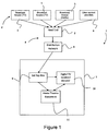
- Figure 1 is a schematic illustration of a signal distribution chain 1, including audio and video content sources 2, end consumer equipment 3 located in the home, and an intermediate transmission network 4.
- Sources of audio and visual signal content include broadcast sources 5 such as commercial and non-commercial television and/or radio channels. These may be international, national, regional or local channels. Broadcast sources are assumed to include digital signals encoded in any of the formats mentioned above, including, MPEG-1 Layer II, HE-AAC (version 1 or 2) and/or Dolby DigitalTM. Other formats may be possible, including MPEG-1 and 2 layer III, AAC, LC-AAC, (Low Complexity Audio Advanced Coding), DTS, DTS-ES, Dolby DigitalTM Plus, Opus, and Ogg Vorbis.
- MPEG-1 Layer II such as commercial and non-commercial television and/or radio channels. These may be international, national, regional or local channels.
- Broadcast sources are assumed to include digital signals encoded in any of the formats mentioned above, including, MPEG-1 Layer II, HE-AAC (version 1 or 2) and/
- Audio and visual signal content sources also include other providers of content 6, such as pay per view video, managed internet television services, "over the top” (OTT) internet video services, audio from open web browsing, internet radio, podcasts, commercial providers, and subscription channels.
- OTT over the top
- Data from the audio and video content sources 12 is passed to a head end service 7 for bundling with other available data for subsequent transmission to an end receiver over the distribution network 8.
- This may include one or more of cable, satellite and over the air links.
- the digital signals transmitted by the head end over the distribution network will include signals encoded in different data formats according to the source.
- multiple head ends may work to common or agreed standards delivering one or more channels to end users via each head end, or the head end function may be split between multiple sites and/or multiple devices.
- the transmitted digital signals are transmitted via the distribution system 4 and received at the end user equipment 3 for decoding.
- the signal is received initially at a set top box 9 for decoding or pass-through.
- the signal is then passed to reproduction devices, including digital television receiver 10 and to home theatre equipment 11.
- the digital television receiver 10 is assumed to an integrated receiver/decoder, meaning that it has the capability to decode audio and video bit streams.
- the digital television receiver 10 is also connected to home theatre equipment 11, including an amplifier and one or more speakers for audio output.
- the set top box 9 may output the received signal via a number of different output mechanisms including HDMI (High Definition Multimedia Interface) and S/PDIF (Sony/Philips Digital Interconnect Format) connections, RCA or SCART connectors, or to a headphone socket.
- HDMI High Definition Multimedia Interface
- S/PDIF Synchronization/Philips Digital Interconnect Format
- Broadcast sources 5 may transmit data in MPEG-1 Layer II, HE-AAC or Dolby DigitalTM, or any of the other formats discussed above.
- MPEG-1 layer II is to be transmitted at a target Level of -23LUFs (that is -23dBFS using the loudness measure defined in EBU R128), while Dolby DigitalTM may be decoded to a reference level of -20dB, -23dB, -27dB, or -31 dB.
- Decoding the encoded audio data to an LPCM output may take place in any of the set top box 9, the digital television receiver 10, or the home theatre equipment 11, according to the capabilities of the device, and the preferences of the user.
- the digital bit stream is decoded.
- the STB 9, the TV 10, and the home theatre equipment 11 may therefore output one or the other of a decoded bit stream, or the original undecoded bit stream.
- connections such as HDMI and SPDIF connections
- HDMI and SPDIF connections can affect the desired target level for the PCM signal, and so can have an effect on the perceived loudness of the output audio experienced by the user.
- some home theatre equipment will automatically reduce a LPCM signal received at its input in comparison to its internal audio decoder levels.
- the STB 9, in the example embodiments that follow is provided with software for equalising the perceived loudness of the different audio signal encodings and formats that it can output, whether the signal is output as a decoded LPCM signal, or as an undecoded digital bit stream.
- the software allows the STB to determine what reference level the sink device (end consumer equipment) is using, and adjust the LCPM loudness level or the audio format metadata to match. This is achieved by asking the user to perform a comparison test of different audio clips, each clip encoded in a particular format.
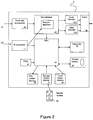
- FIG. 2 shows an embodiment of a set-top box 9 according to an example embodiment.
- the set-top box 9 may include a digital video recording (DVR) function.
- a receiving device such as a tuner/demodulator 20 is provided to receive broadcast streams, internet delivered streams or the like containing transmitted programmes.
- the tuner/demodulator is connected to an input 21 at which terrestrial, satellite or cable audio and video signals can be received for viewing, and to a demultiplexer 22.
- Input audio and video data can also be received via internet connection 23, which outputs a signal to demultiplexer 22 and to a CPU or processor 24.
- a user interacts with the STB 9 via a remote control 25 or via a touch based control interface 26, such as channel selection buttons provided on the housing of the STB 9, to select a particular programme/channel to watch or record.
- the signals from the remote control are received by remote control receiver 31 in the STB 9.
- the remote control receiver 31 and front panel buttons 26 may be referred to as input interfaces.
- the processor 24 receives instructions from the remote control receiver 31 and/or the touch based control interface and causes the demultiplexer block 22 to select the programme stream indicated by the user, either sending it to an audio decoder 27a and/or video decoder 27a, for decoding to an LPCM encoded signal for subsequent output at output 28, or passing through the undecoded bit stream to output 28 directly.
- Audio and video decoder 27a and 27b therefore necessarily includes at least codecs to convert a received bit stream in a digital format such as MPEG -1 Layer II, AC-3, and HE-AAC to a signal represented by PCM or LPCM.
- Output 28 may be connected to a reproduction device such as television 10 or home theatre equipment 11 via one or more connections, such as HDMI (High Definition Multimedia Interface) and SPDFI (Sony/Philips Digital Interconnect Format) connections, RCA or SCART connectors, or by modulated VHF or UHF output. Any interface, present or future which can carry an undecoded audio stream and/or a decoded PCM or LPCM audio stream, is contemplated within the invention.
- the selected programme stream may be passed to a storage device 29 to be watched later, or to transcoder 30 for converting to a different audio encoding.
- Transcoding for example may be used when adapting the audio and/or video encoding from the one that is broadcast to one which can be decoded by some other target device, for example a tablet or smart phone. This may entail changing the codec, bitrate, resolution and/or video frame rate, audio sampling rate to match the capabilities of the target device.
- transcoding may be used when the input Surround Sound needs to be output to another device for decoding to 5.1 channels, but the input format (for example HE-AAC or Enhanced AC-3) cannot be decoded by the other device, and so must be transcoded into a format that the other device can decode (for example AC-3).
- the gain adjustments that are discussed elsewhere can be incorporated into the transcoding process by directly changing the gain of the audio signal during transcoding, or applied to the loudness metadata that may be copied or transcoded from the target format to the destination format.
- the STB 9 also includes a non volatile memory 32 containing control and processor instructions for operation of the STB 9.
- Figure 3 shows an example graphical user interface generated by the processor 24 of the STB 9 and output to a display device for viewing via output 28.
- the purpose of the graphical user interface is to guide the user through an audio equalisation process for audio signals in different audio signal formats, whether decoded in the STB 9 or passed through without decoding to the output 28.
- This process may be referred to as a 'wizard' as is known in the art.
- Figure 4 is a schematic illustration of the equalisation process itself, and Figure 5 shows a region of memory in the STB 9 used to store the results of the equalisation process. This may be non volatile memory 32.
- the equalisation process begins. This may happen automatically when the STB is started up for the first time, as part of an initialisation process. Where possible, the STB may wait to begin this process until it detects that its output ports have been connected to downstream equipment, or until the user indicates that the necessary connections have been made. The STB may include software to prompt the user to do this. Alternatively, the audio initialisation process may be begun at any time following selection of an appropriate option from a menu. This allows the user to recalibrate their audio visual entertainment system if they ever change their TV or amplifier configuration.
- the wizard operates by guiding the user through a process in which the user is played at least two audio clips, typically one decoded from the bitstream and output as LPCM, and one the undecoded pass-through signal to be decoded by the user equipment.
- the two clips may both be undecoded pass-through signals to be decoded by the user equipment.
- the graphical user interface requires the STB to be properly connected to the end user equipment such as the television or home theatre speakers.
- the two audio clips will ultimately be heard by the user via the speakers of the television or the speakers of the home theatre system. Both the decoded and the pass through audio signal will be transmitted to the speakers via the same connections.
- the audio clips that are played will consist of a suitable level matching signal, such as one or more of pink or white noise, narrow band noise, other types of noise, and speech.
- a suitable level matching signal such as one or more of pink or white noise, narrow band noise, other types of noise, and speech.
- Common reference levels are known to be -20dB, -23dB, -27dB, and -31dB, and it is helpful to make the audio clips available at these levels. This may be by storing separate clips with the appropriate input loudness and/or reference data, or alternately by storing a single clip and outputting it from the STB with the necessary gain or attenuation.
- the first two audio formats to be loudness equalised comprise an MPEG-1 Layer II signal decoded to LPCM and an AC-3 signal.
- these signals are played to the user in sequence and a first screen of the graphical user interface is output on a display (equalisation of these two audio formats alone is expected to address the audio mismatch problems of most consumers, meaning that the later steps may be optional. They are included here however for completeness).
- Figure 3 shows a first screen of the graphical user interface, corresponding to the user being played two identical audio clips, "AUDIO A” decoded from MPEG-1 Layer II and output as LPCM, and "AUDIO B” received as a bitstream in the AC-3 format and passed through the STB without decoding to the output.
- the graphical user interface asks the user to indicate which signal is perceived as being louder, and presents the user with options for reply.
- the user can select a first radio button to indicate that Audio clip A is louder, a second button to indicate that Audio Clip B, is louder, a third button to indicate that they both appear to be as loud as each other, and a fourth button to indicate that they are not sure, and would like to hear the clips again.
- the fourth button is optional. Selection can be via the STB remote control or handset, via user input buttons on the STB chassis, or indeed any other supported input method.
- the STB begins the process by outputting the two audio clips at audio levels that are likely to be correct.
- the MPEG-1 Layer II stereo stream would be output with 8dB of attenuation (assuming an initial expected audio level of -23dB), to match the AC-3 stream typically decoded to a reference level of -31dB.
- the initial loudness values chosen by the STB were correct and would be saved in memory for that combination of outputs (step 4 of Figure 4 ). This is illustrated in Figure 5A for the two audio formats that are the subject of the comparison. If required, the wizard then moves onto the next comparison of audio clips, say MPEG-1 Layer II and HE-AAC and repeats the equalisation process for two different services or audio formats in step 5.
- the only audio formats that will require comparison will be those that are broadcast.
- the wizard can be configured accordingly to compare the required audio formats. If the audio formats that are in use changes, it is also possible to update the software in the STB to account for this. Updating the STB software controlling the wizard can be carried out remotely. Alternatively, the STB can be configured to scan the available broadcast transmissions that are available during the automatic tuning process, and record which audio formats are in use. This information can then be used to control the audio formats which feature in the comparison wizard.
- Step 6 of Figure 4 the audio settings for the signal are adjusted, and the original signals are then replayed (by returning to step 2, 5 or 7 respectively.
- Most listeners are able to detect a difference of 6dB.
- gain it is possible to apply gain to the signals, and the application of gain may be necessary to ensure that equalisation process takes place.
- the step size may be set to a value that is different to the value of 6dB mentioned above, either automatically or via suitable controls provided by the wizard.
- a smaller step size may be desirable if a step size of 6dB results in an audio loudness that overshoots the optimal position, for example causing an audio signal A that was perceived as louder than the comparison audio signal B, being perceived in the following step as quieter than the comparison audio signal B.
- Step sizes of 2dB or 1dB are therefore also possible within the comparison process, but should in general only be used after the user has repeatedly reported that the signal under review is first perceived as louder, then quieter, and so on. This detection may be carried out automatically as noted above.
- the equalisation process is set up to perform a comparison between at least three pairs of signals; 1) MPEG-1 Layer II and AC-3 2.0) MPEG-1 Layer II and HE-AAC; and 3) AC-3 2.0 (stereo) and AC 3 5.1 (surround sound).
- the comparison could be performed on other pairs of services not just those listed here, and the cyclical process of Figure 4 is accordingly illustrated as continuing beyond the three comparisons explicitly described.
- the same audio formats may be presented for equalisation but processed with and without audio description, and optionally with and without particular downmix coefficients, since the misapplication of channel downmix coefficients in a downstream device will cause the loudness to change.
- This variety of signals means that potential downstream faults (such as loudness mismatches due to the manner in which the downstream equipment treats different formats or streams with different characteristics in a different manner) can be caught more easily.
- pre-encoded, or on the fly audio clips may be captured in the STB and used in the comparison. These comparison measures may be available in a professional or 'expert' set up process separately accessed via the wizard. It is preferable to use pre-encoded clips with known levels, but it is also contemplated that there might be some circumstances where the user would prefer to use real broadcast material as this might reveal some new problems that the pre-encoded clips have not been designed to address.
- step 4 the memory is updated in step 4, with the adjustment gain values to be applied to the signals.
- step 4 As each cycle of the comparison is performed a further entry is saved into the memory space.
- the progression of data is illustrated in Figure 5 by way of example.
- FIGS 5A to 5C are schematic illustrations of the memory space allocation used in the STB according to one example.
- Each of the available codecs is listed the left hand column, in the middle column is the anticipated reference or target level at output, and in the right hand column is the desired gain or attenuation determined by the equalisation process. It will be appreciated that the gain or attenuation is relative to the output levels usually applied by the STB.
- the MPEG-1 Layer II signal is expected to be received at -23dB, and requires an -8dB attenuation to match the loudness of the Dolby DigitalTM signal decoded to -31dB.
- the expected MPEG level can be anticipated from the country in which the STB is likely to be deployed and information about the levels used in that country. If for any reason the MPEG-1 Layer II signal or AC-3 format audio signal are output at different loudnesses on the end user equipment, then the actual gain desired may be different, but this will be determined by the equalisation process.
- the most likely initial adjustment may be applied to the signal, different to corrections according to the local standards and according to knowledge of the specific national standard under which the international channel originated.
- Figures 5D and 5E are schematic illustrations of memory organisations used in the STB according to alternative examples.
- the expected level of the audio format is not used, and the information recorded in memory is simply the amount of gain needed to bring the loudness of one audio format into line with another.
- the STB uses each of the non MPEG-1 Layer II formats as a base line and records the gain necessary to make the MPEG-1 Layer II audio stream match the loudness of decoded data for each respective audio format.
- the right hand column means that MPEG-1 Layer II needs to be attenuated by 8dB in each case, from which it can be assumed that the loudness reproduction of data in each of the respective audio formats shown in the left hand column is identical.
- the STB can then determine the difference between any two formats shown in the table by simple subtraction.
- the STB will know what gain or attenuation should be applied to the audio signals it outputs, taking into account the particular user equipment to which it is connected. For each available audio codec, a correction value, in terms of a positive or negative gain value is stored. This correction value can then be applied to all audio signals decoded with that codec.
- the loudness of the output signal is simply scaled by the dB level indicated in the equalisation process.
- the STB is configured to output PCM signals or LPCM signal at a level of -8dB below reference, but the test reveals that this signals sounds louder than the AC-3 signal decoded downstream at the home theatre equipment, then it may apply a further attenuation of -6db (-14dB) to the signal on output.
- the STB will adjust the metadata that the downstream user equipment responds to in order to effect the change. For example, if the equalisation software indicates that the AC 3.5.1 should be played at a higher level than the AC-3 2.0 bitstream, the STB can adjust the dialnorm metadata used by Dolby DigitalTM to indicate the desired output loudness. These level adjustments can therefore be applied to all audio signals that it outputs, broadcast, IP, etc.
- the intent would be to minimise the gain changes applied to the audio formats output as bitstreams, where changing the metadata is relied upon to implement that gain change.
- loudness equalisation can be carried out solely by the gain applied to MPEG-1 Layer II data, it is preferable if the audio format gain is not adjusted.
- the gain is necessarily applied to the audio format data, then it is preferable if this can be minimised by changing the MPEG-1 Layer II data partly to compensate.
- the intent would also be to avoid increasing the gain of any format above 1 (in these examples making the audio level in decibels level larger, that is less negative) unless there was some reason to believe that doing so would not introduce clipping. Preference would be given to the most used audio formats (known from a channel scan, or a predefined preference). If simple logical checks failed to reveal the best compromise, a weighted average or least means squares procedure could be used to determine the best (or most tolerable) gain values. The range of possibilities is limited, since the relative gains must be maintained to enable the loudness equalisation to work, and steps smaller than 0.5dB are essentially inaudible, and need not be considered.
- any apparent discrepancies in the results obtained from the user may be checked by a re-test, potentially using different pairs of codecs in the new test. For example, if all comparisons are carried out against MPEG-1 layer II (codec A) but codecs B and C which are not known to have different reference levels in any commercially available equipment were found to require a different gain correction to match MPEG-1 layer II, then the user may be asked to directly compare B with C. If the results match those of the separate comparisons with MPEG-1 layer II, then they should be used. If the results indicate that B and C have the same loudness, then the previous erroneous comparison with MPEG-1 layer II may be repeated or (if it is clear which is in error) discarded. Conversely, if one of the original tests involved B against C and revealed a large unexpected difference, it would be wise to test MPEG-1 layer II against B, and then MPEG-1 layer II against C.
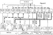
- Figure 6 shows the audio functionality within the STB according to the present example.
- the output of the wizard described above in connection with Figures 3 to 5 sets the value of variables a, b, c, d, e, f, and g which are the values fed to the variable attenuators and metadata adjusters, used to match the loudness of the audio signals of various formats before output from the STB. This process is discussed below.
- the functional elements in the logical diagram in Figure 6 correspond to real hardware system components, and may be implemented in the STB as separate components as shown. However, an efficient or economic implementation may combine several functional components into a single physical element.
- a system-on-a-chip silicon implementation may include DolbyDigitalTM (DD) and DolbyDigital+ TM (DD+) decoding within a single element; further the 3dB PCM attenuators immediately below these elements may also be combined within that decoder.
- DD DolbyDigitalTM
- DD+ DolbyDigital+ TM
- Figure 6 shows the flow of the audio information beginning at the top of Figure 6 where it is demultiplexed from the transport stream, which may contain one or more video and audio streams, associated data etc, by demultiplexer 60, to the bottom of Figure 6 where the audio signal is output from the STB via one or more suitable connectors 90, 92, 94 and 96.
- Video processing is not shown, but is assumed to take place in parallel for any AV content.
- the functionality illustrated in Figure 6 expresses in more detail the functionality contained within the audio decoder 27a and/or CPU of Figure 2 .
- the different audio formats are output on separate lines; different audio formats will be flagged as such in the transport stream and carried on different packet identifiers (PIDs), so the separation may be implanted as a standard function of a demultiplexer, and once the appropriate PIDs have been identified from known DVB-SI tables (that is, tables in a format defined by the DVB standard which include entries labelling different audio formats in a known standardised format), this function is handed to a dedicated PID filter.
- PIDs packet identifiers
- the different audio format paths are indicated by different lines types: the HE-AAC path is shown as a simple dashed line 61; the DD+ path is shown dotted line 62; the DD path is shown as a thick dashed line 63; the MPEG-1 layer II path is shown as a thin line 64; the multichannel 5.1 PCM path is shown as a thick solid line 65; stereo PCM and other signals are shown by regular lines 66. All possible paths are shown, but at a given moment, only the chosen audio stream will be passed to the appropriate audio decoder, transcoder, or passed through, and the other paths will not be used, or in practice will not exist due to the dynamic nature of the internal multiplexed bus structure on such devices.
- Figure 6 shows a number of decoders, transcoders and pass through blocks including: AAC pass-through block 70, DD+ pass-through block 71, DD pass-through block 72, AAC to DD Transcoder 73, DD+ to DD transcoder 74, MPEG-1 decoder 75, AAC decoder 76, DD+ decoder 77, and DD decoder 78.
- Mono source signals are usually carried as two identical "stereo" channels, so are still treated as 2.0.
- the multichannel signals can be decoded to the original number of channels, or downmixed to stereo (2.0) within the decoder.
- Stereo signals can be decoded to the original number of channels, or upmixed to 5.1 within the decoder, either by sending the original 2.0 feeds to the front left and right speaker feeds and leaving the other channels silent, or by using some more sophisticated upmixing algorithm that spreads the signal between more than two of the 5.1 outputs.
- the Dolby decoder(s) will normally set a target level of -31 dB for multichannel outputs, and -20dB for stereo outputs.
- other stereo formats MPEG-1 layer II, HE-AAC stereo
- 3dB attenuators 80 and 81 are added to the stereo output(s) of the Dolby decoder(s) 77 and 78 to match the level of the other stereo audio sources.
- the Dolby decoders may be adjusted to set a target level of -23dB, and those particular attenuators would no longer be necessary.
- An 8dB attenuator 82 is added to the feed from the stereo formats to the 5.1 outputs 94, to match the stereo signals at -23dB to the 5.1 signals at -31dB.
- those two stereo channels are typically fed to the front left and front right speaker feeds of the 5.1 output.
- -23 means a stereo (2.0) output at a target level of -23dB
- 5.1, -31 means a multichannel (up to 5.1) output at a target level of -31 dB.
- transcoders 73 and 74 from HE-AAC and DD+ to DD are included. These transcoders convert the audio from one coding format to another, but attempt to preserve the loudness and loudness metadata during the conversion.
- the "pass through” elements 70, 71 and 72 are essentially “no operation” elements (they do nothing), and are shown to clarify that no change is made to the signal at that point (compared with the alternative paths on the same line of Figure 6 which do include real functionality).
- digital-to-analogue convertors 83 and 84 which convert the LPCM digital signals to analogue signals, are shown above the analogue outputs 94 and 96.
- a volume control device either in the form of another variable PCM attenuator before the DACs, or an analogue device within or after the DACs, may be included but is not shown here.
- the analogue outputs 94 and 96 are a useful example of current state-of-the-art loudness matching in a scenario where no unpredictable downstream devices are involved.
- the loudness of the different signal sources via the same analogue output 94 and 96 is matched within the STB by careful design and consideration, i.e. controlling the target volumes of the various decoders, knowing the broadcast level of MPEG-1 audio (which does not respond to a target level or have any built-in concept of a loudness reference level), and including the appropriate attenuators in-line to match these disparate levels.
- LPCM 2.0 or a DD bitstream may be output.
- the switch 97 above the SPDIF output is designed to automatically select the DD path (illustrated by the thick dashed line) when multichannel audio is available, and to select the stereo path (illustrated by the normal line) when only stereo audio is available.
- the DD path will be selected for such content to allow dynamic range metadata to be sent downstream.
- the DD path will not usually be used for stereo content originating in other formats, because though it is possible to transcode HE-AAC and even MPEG-1 layer II to DD, this would unnecessarily degrade the audio quality.
- the LPCM audio passes through the MPEG decoder 75 to a variable attenuator 85, set to attenuate the audio by the value "g", which is the output of the wizard for LPCM (decoded MPEG-1 layer II) audio when (in this example) tested via equipment connected to the SPDIF output.
- the resulting audio samples may be dithered, rounded, truncated etc.
- the conversion from dB to scale factor may occur elsewhere (the memory structure illustrated in Figure 5 may even store scale factors rather than dB values), and the LPCM attenuator may be integrated within some other part of the audio pipeline, but the overall effect will be as described above.
- the DD audio passes through a variable metadata adjustment block 86, set to adjust the loudness metadata (i.e. in this case, dialnorm) to attenuate the audio by the value "f", which is the output of the equalisation process for DD audio when tested via the equipment connected to the SPDIF output.
- the variable metadata adjustment block 86 parses the coded audio bitstream to find all instances of the appropriate metadata element(s) (in this case, dialnorm), and adjusts them by the amount "f".
- the final stage of the wizard may already have "processed” these values to minimise the absolute value of "f", changing the value of "g” to compensate as long as this does not lead to excessive amplification and hence clipping.
- the HDMI output 90 acts in a similar way, but with additional functionality which adds complexity to the discussion.
- the HDMI specification includes various methods whereby a source device (in this instance, the STB shown in Figure 6 ) can query the sink device (in the case, a TV or home cinema amplifier etc) to determine which formats the sink device can decode.
- the sink device may support DD+, and may support 5.1 LPCM, and may even support HE-AAC decoding.
- the decision must be made whether to "pass-through" that bitstream to the sink device for decoding, or to decode it with within the STB.
- the sink device claims to decode a given format it is passed through.
- Some STBs offer a manual over-ride to this, forcing the decoding to be carried out with the STB. This is provided for the situation where the sink device is in error, or does not handle a particular source as the user wishes. In the present case, an output from the wizard revealing that a particular format is decoded to the wrong loudness by the sink device, is one good reason to decode that format within the STB.
- the five switches 98 above the HDMI output are set to pass-through any format that the HDMI sink device can decode, there are exceptions.
- the sink device does not (or, after assessing the loudness matching as above, "should not") accept the pass through audio
- the alternatives in order of preference are LPCM 5.1, transcode to DD, or LPCM 2.0. If the source is stereo then LPCM 2.0 will always be acceptable (support is mandatory in the HDMI specification).
- the five switches 98 are set based on the input audio format, the capabilities of the sink, and the need to implement loudness matching.
- a pair of dual/parallel switches 98.1 to 98.5 ensure that the correct attenuation value (a,b,c,d, and e in Figure 6 ) is selected alongside the associated audio format. So, for example, if an HE-AAC stream is passed through by one switch 98.1, value "a” is sent to the variable metadata adjustment function 87 by the corresponding dual/parallel switch 98.2; value "a” being the attenuation value generated by the wizard for listening to HE-AAC encoded audio via the equipment attached to the HDMI output 90.
- value "e” is sent to the variable LPCM attenuator 88 by another dual/parallel switch 98.4; value "e” being the attenuation value generated by the wizard for listening to 5.1 LPCM via the equipment attached to the HDMI output.
- Swicth 98.5 automatically selects between the outputs of the variable metadata adjustment block 87 and variable LPCM attenuator 88 to supply a signal to the HDMI output 90 as appropriate. In this way, the appropriate attenuation or metadata adjustment is always used with each format.
- the wizard process identifies issues in downstream equipment requiring a different level of attenuation for Dolby Digital stereo (2.0) content than for Dolby Digital multichannel (e.g. 5.1) content
- Dolby Digital multichannel e.g. 5.1
- one of two measures will be used. Either the 5.1 content will be sent-out in pass-through mode (with the required change, if any, to the dialnorm data), and the 2.0 content will be decoded to PCM before being sent out (with the required attenuation to the LPCM data), or alternatively an additional element will be added (not shown on Figure 6 ) to differentiate between 2.0 and 5.1 bitstreams, and to adjust the dialnorm data by a different amount for each, as appropriate (i.e. as revealed by the wizard).
- Figure 6 shows the sum total of almost all processing that could be required, but a real implementation may only offer a subset, and a working version in a user's home may only actively use a small part.
- the wizard has been described as presenting pairs of audio clips for comparison, it will be appreciated that more than two audio clips could be played in succession.
- the user could be asked to answer different questions, such as to grade them in order of loudness, or indicate a loudness score for each.
- the software could apply suitable gain adjustments to the signal and replay for confirmation.
- the user could be presented with a volume slider that they are required to adjust for each codec so that the levels can be set for each codec accordingly.
- the user interface and equalisation wizard described above is preferred as it is the most simple to understand, and benefits from allowing even the most unskilled user to optimise the output.
- a particular advantage provided by the embodiments described above is that the user does not need to have any specialist technical knowledge of their audio equipment to be able to optimise their audio output. Furthermore, as the optimisation process is based on the user's perception of the audio, not on the type of audio equipment being used, the optimisation process can be effective regardless of the type of equipment attached to the output. All that is necessary to keep the optimisation process effective is to keep the optimisation software updated with options to equalise the output audio based on the codecs that are used in the industry at the time.
- the user will know that the STB is operating properly, and that any remaining audio level discrepancies are features of the broadcasts themselves.
Claims (15)
- Procédé mis en oeuvre par ordinateur pour commander un dispositif de réception audio (9) afin d'égaliser les niveaux d'intensité sonore de signaux audio sortis pour lecture sur un dispositif de lecture audio connecté, le procédé comprenant le fait de :a) sortir (2, 5, 7) au moins un premier et un deuxième signal audio à une sortie audio pour lecture sur un dispositif de lecture audio, le premier et le deuxième signal étant codés numériquement en des formats audio différents, le premier signal audio étant sorti à un premier niveau d'intensité sonore et le deuxième signal audio étant sorti à un deuxième niveau d'intensité sonore ;b) commander (3) un affichage connecté pour inviter une entrée d'un utilisateur indiquant l'intensité sonore relative du premier signal audio comparé au deuxième signal audio ;c) sur la base de l'entrée utilisateur, ajuster (6) un ou plusieurs d'entre le au moins un premier et un deuxième niveau d'intensité sonore jusqu'à ce que l'utilisateur indique que ceux-ci sont perçus comme entendus au même niveau d'intensité sonore ;d) conserver (4) les niveaux d'intensité sonore en mémoire pour reproduction future des signaux audio.
- Procédé mis en oeuvre par ordinateur selon la revendication 1, dans lequel l'étape b) comprend le fait de commander un dispositif d'affichage (10) couplé au dispositif de réception audio (9) pour présenter une interface graphique utilisateur, l'interface graphique utilisateur recherchant une entrée d'un utilisateur pour commander un ou plusieurs d'entre le premier et le deuxième niveau d'intensité sonore.
- Procédé mis en oeuvre par ordinateur selon la revendication 1 ou 2, dans lequel
l'étape b) comprend le fait de rechercher une entrée d'un utilisateur indiquant lequel d'entre au moins un premier et un deuxième signal audio est le plus fort ; et
l'étape c) comprend :sur la base de l'entrée utilisateur indiquant que le au moins un premier et un deuxième signal audio sont perçus comme étant aussi forts l'un que l'autre, le fait de conserver les niveaux d'intensité sonore en mémoire pour reproduction future des signaux audio ; etsur la base de l'entrée utilisateur indiquant que l'un d'entre le premier et le deuxième signal audio est plus fort que l'autre, le fait d'ajuster le niveau d'intensité sonore de sortie de l'un ou de plusieurs d'entre le premier et le deuxième signal audio et de répéter les étapes a) à c). - Procédé mis en oeuvre par ordinateur selon l'une quelconque des revendications précédentes, dans lequel le fait d'ajuster les niveaux d'intensité sonore de sortie comprend le fait de changer l'intensité sonore de sortie de l'un de soit le premier et de soit le deuxième signal audio d'un nombre de décibels prédéterminé.
- Procédé mis en oeuvre par ordinateur selon l'une quelconque des revendications précédentes, dans lequel le premier et le deuxième signal audio sont sortis initialement avec un premier facteur de correction destiné à égaliser une intensité sonore avec l'autre.
- Procédé mis en oeuvre par ordinateur selon l'une quelconque des revendications précédentes, dans lequel les étapes sont exécutées par un dispositif de réception audio (9), comprenant l'un d'entre un récepteur/décodeur intégré (décodeur numérique) ou une TV intégrée.
- Procédé mis en oeuvre par ordinateur selon l'une quelconque des revendications précédentes, dans lequel l'intensité sonore du premier signal audio est ajustée, et dans lequel le premier signal de sortie audio est décodé par le dispositif de réception audio en un signal numérique modulé par impulsions codées, et dans lequel le deuxième signal audio est sorti comme un train binaire non décodé à décoder par l'équipement audio en aval.
- Procédé mis en oeuvre par ordinateur selon l'une quelconque des revendications précédentes, dans lequel l'intensité sonore du deuxième signal audio est ajustée, et dans lequel ajuster l'intensité sonore comprend ajuster des métadonnées d'intensité sonore dans le signal.
- Procédé mis en oeuvre par ordinateur selon l'une quelconque des revendications précédentes, dans lequel le premier et le deuxième signal audio sont codés en des formats audio différents sélectionnés parmi MPEG-1 Layer II, MPEG-1 et 2 Layer III, HE-ACC version 1 ou 2, AAC, LC-AAC, DTS, DTS-ES, Dolby Digital, Dolby Pulse, Dolby Digital Plus, NICAM, Opus, Ogg Vorbis, LPCM et un signal analogique converti en LPCM.
- Dispositif de réception audio, comprenant du logiciel de commande stocké sur un processeur pour égaliser les niveaux d'intensité sonore de signaux audio sortis pour lecture sur un dispositif de lecture audio connecté, dans lequel le processeur est opérationnel pour:a) sortir (2, 5, 7) au moins un premier et un deuxième signal audio à une sortie audio pour lecture sur un dispositif de lecture audio, le premier et le deuxième signal étant codés numériquement en des formats audio différents, le premier signal audio étant sorti à un premier niveau d'intensité sonore et le deuxième signal audio étant sorti à un deuxième niveau d'intensité sonore ;b) commander (3) un affichage connecté pour inviter une entrée d'un utilisateur indiquant l'intensité sonore relative du premier signal audio comparé au deuxième signal audio ;c) sur la base de l'entrée utilisateur, ajuster (6) un ou plusieurs d'entre le au moins un premier et un deuxième niveau d'intensité sonore jusqu'à ce que l'utilisateur indique que ceux-ci sont perçus comme entendus au même niveau d'intensité sonore ;d) conserver (4) les niveaux d'intensité sonore en mémoire pour reproduction future des signaux audio.
- Dispositif de réception audio selon la revendication 10, dans lequel l'étape b) comprend commander un dispositif d'affichage (10) couplé au dispositif de réception audio (9) pour présenter une interface graphique utilisateur, l'interface graphique utilisateur recherchant une entrée d'un utilisateur pour commander un ou plusieurs d'entre le premier et le deuxième niveau d'intensité sonore.
- Dispositif de réception audio selon la revendication 10 ou 11, dans lequel
l'étape b) comprend rechercher une entrée d'un utilisateur indiquant lequel d'entre au moins un premier et un deuxième signal audio est le plus fort ; et
l'étape c) comprend :sur la base de l'entrée utilisateur indiquant que le au moins un premier et un deuxième signal audio sont perçus comme étant aussi forts l'un que l'autre, conserver les niveaux d'intensité sonore en mémoire pour reproduction future des signaux audio ; etsur la base de l'entrée utilisateur indiquant que l'un d'entre le premier et le deuxième signal audio est plus fort que l'autre, ajuster le niveau d'intensité sonore de sortie de l'un ou de plusieurs d'entre le premier et le deuxième signal audio et répéter les étapes a) à c). - Dispositif de réception audio selon l'une quelconque des revendications 10 à 12, dans lequel ajuster les niveaux d'intensité sonore de sortie comprend changer l'intensité sonore de sortie de l'un de soit le premier et de soit le deuxième signal audio d'un nombre de décibels prédéterminé.
- Dispositif de réception audio selon l'une quelconque des revendications 10 à 13, dans lequel le premier et le deuxième signal audio sont sortis initialement avec un premier facteur de correction destiné à égaliser une intensité sonore avec l'autre.
- Programme informatique qui lorsque exécuté sur un processeur d'ordinateur d'un dispositif de réception audio, fait que le processeur d'ordinateur effectue les étapes selon l'une quelconque des revendications 1 à 9.
Priority Applications (5)
| Application Number | Priority Date | Filing Date | Title |
|---|---|---|---|
| EP13178947.1A EP2833549B1 (fr) | 2013-08-01 | 2013-08-01 | Commande de sonie pour équipement de réception et de décodage audio |
| EP14179486.7A EP2840712B1 (fr) | 2013-08-01 | 2014-08-01 | Commande de volume pour équipement de réception et de décodage audio |
| US14/449,525 US9696960B2 (en) | 2013-08-01 | 2014-08-01 | Loudness level control for audio reception and decoding equipment |
| US14/449,546 US9430185B2 (en) | 2013-08-01 | 2014-08-01 | Loudness level control for audio reception and decoding equipment |
| US15/635,810 US10063204B2 (en) | 2013-08-01 | 2017-06-28 | Loudness level control for audio reception and decoding equipment |
Applications Claiming Priority (1)
| Application Number | Priority Date | Filing Date | Title |
|---|---|---|---|
| EP13178947.1A EP2833549B1 (fr) | 2013-08-01 | 2013-08-01 | Commande de sonie pour équipement de réception et de décodage audio |
Publications (2)
| Publication Number | Publication Date |
|---|---|
| EP2833549A1 EP2833549A1 (fr) | 2015-02-04 |
| EP2833549B1 true EP2833549B1 (fr) | 2016-04-06 |
Family
ID=48915890
Family Applications (2)
| Application Number | Title | Priority Date | Filing Date |
|---|---|---|---|
| EP13178947.1A Active EP2833549B1 (fr) | 2013-08-01 | 2013-08-01 | Commande de sonie pour équipement de réception et de décodage audio |
| EP14179486.7A Active EP2840712B1 (fr) | 2013-08-01 | 2014-08-01 | Commande de volume pour équipement de réception et de décodage audio |
Family Applications After (1)
| Application Number | Title | Priority Date | Filing Date |
|---|---|---|---|
| EP14179486.7A Active EP2840712B1 (fr) | 2013-08-01 | 2014-08-01 | Commande de volume pour équipement de réception et de décodage audio |
Country Status (2)
| Country | Link |
|---|---|
| US (3) | US9430185B2 (fr) |
| EP (2) | EP2833549B1 (fr) |
Families Citing this family (18)
| Publication number | Priority date | Publication date | Assignee | Title |
|---|---|---|---|---|
| US8712362B2 (en) | 2008-07-26 | 2014-04-29 | Enforcement Video, Llc | Method and system of extending battery life of a wireless microphone unit |
| US9787273B2 (en) * | 2013-06-13 | 2017-10-10 | Google Technology Holdings LLC | Smart volume control of device audio output based on received audio input |
| EP2833549B1 (fr) * | 2013-08-01 | 2016-04-06 | EchoStar UK Holdings Limited | Commande de sonie pour équipement de réception et de décodage audio |
| US9661435B2 (en) * | 2014-08-29 | 2017-05-23 | MUSIC Group IP Ltd. | Loudness meter and loudness metering method |
| EP4156180A1 (fr) | 2015-06-17 | 2023-03-29 | Fraunhofer-Gesellschaft zur Förderung der angewandten Forschung e.V. | Commande de volume sonore pour interactivité d'utilisateur dans des systèmes de codage audio |
| US9837086B2 (en) * | 2015-07-31 | 2017-12-05 | Apple Inc. | Encoded audio extended metadata-based dynamic range control |
| US9590580B1 (en) * | 2015-09-13 | 2017-03-07 | Guoguang Electric Company Limited | Loudness-based audio-signal compensation |
| DE102015217565A1 (de) * | 2015-09-15 | 2017-03-16 | Ford Global Technologies, Llc | Verfahren und Vorrichtung zur Verarbeitung von Audio-Signalen |
| CN106017384B (zh) * | 2016-07-07 | 2018-12-14 | 天津市宇润德金属制品有限公司 | 一种具有抗温性能的测厚仪 |
| US20180278004A1 (en) * | 2017-03-27 | 2018-09-27 | Delphi Technologies, Inc. | Sealed electric terminal assembly and method |
| KR102491646B1 (ko) * | 2017-11-30 | 2023-01-26 | 삼성전자주식회사 | 오디오 신호의 음량에 따라 설정된 해상도에 기반하여, 오디오 신호를 처리하는 방법 및 그 전자 장치 |
| JP7184656B2 (ja) * | 2019-01-23 | 2022-12-06 | ラピスセミコンダクタ株式会社 | 故障判定装置及び音出力装置 |
| CN109803208B (zh) * | 2019-01-31 | 2021-06-11 | 大陆汽车车身电子系统(芜湖)有限公司 | 一种音频文件处理方法及电子装置 |
| CN112073789B (zh) * | 2019-06-10 | 2023-04-14 | 海信视像科技股份有限公司 | 一种声音处理法及显示设备 |
| CN111181516B (zh) * | 2019-12-27 | 2023-09-12 | 中山大学花都产业科技研究院 | 一种音色均衡方法 |
| US11595730B2 (en) * | 2021-03-08 | 2023-02-28 | Tencent America LLC | Signaling loudness adjustment for an audio scene |
| WO2022189341A1 (fr) * | 2021-03-10 | 2022-09-15 | Dolby International Ab | Appareil et procédé de mise à niveau d'audio principal et supplémentaire à partir d'un service de hbbtv |
| US11900961B2 (en) * | 2022-05-31 | 2024-02-13 | Microsoft Technology Licensing, Llc | Multichannel audio speech classification |
Family Cites Families (22)
| Publication number | Priority date | Publication date | Assignee | Title |
|---|---|---|---|---|
| US5784095A (en) * | 1995-07-14 | 1998-07-21 | General Instrument Corporation | Digital audio system with video output program guide |
| DE19818217A1 (de) | 1998-04-24 | 1999-10-28 | Rainer Berthold | Zusatzeinrichtung für einen Fernsehempfänger |
| JP2001224098A (ja) * | 2000-02-14 | 2001-08-17 | Pioneer Electronic Corp | オーディオシステムにおける音場補正方法 |
| US7006645B2 (en) | 2002-07-19 | 2006-02-28 | Yamaha Corporation | Audio reproduction apparatus |
| US7551745B2 (en) * | 2003-04-24 | 2009-06-23 | Dolby Laboratories Licensing Corporation | Volume and compression control in movie theaters |
| US7272235B2 (en) * | 2003-06-26 | 2007-09-18 | Microsoft Corporation | Method and apparatus for audio normalization |
| US7617109B2 (en) * | 2004-07-01 | 2009-11-10 | Dolby Laboratories Licensing Corporation | Method for correcting metadata affecting the playback loudness and dynamic range of audio information |
| US20070121966A1 (en) * | 2005-11-30 | 2007-05-31 | Microsoft Corporation | Volume normalization device |
| GB2429346B (en) * | 2006-03-15 | 2007-10-17 | Nec Technologies | A method of adjusting the amplitude of an audio signal and an audio device |
| US7822498B2 (en) | 2006-08-10 | 2010-10-26 | International Business Machines Corporation | Using a loudness-level-reference segment of audio to normalize relative audio levels among different audio files when combining content of the audio files |
| US20080080722A1 (en) | 2006-09-29 | 2008-04-03 | Carroll Tim J | Loudness controller with remote and local control |
| US9197181B2 (en) * | 2008-05-12 | 2015-11-24 | Broadcom Corporation | Loudness enhancement system and method |
| US8798776B2 (en) * | 2008-09-30 | 2014-08-05 | Dolby International Ab | Transcoding of audio metadata |
| DK2396975T3 (en) * | 2009-02-16 | 2018-01-15 | Blamey & Saunders Hearing Pty Ltd | AUTOMATIC FITTING OF HEARING DEVICES |
| TWI525987B (zh) * | 2010-03-10 | 2016-03-11 | 杜比實驗室特許公司 | 在單一播放模式中組合響度量測的系統 |
| EP2367286B1 (fr) * | 2010-03-12 | 2013-02-20 | Harman Becker Automotive Systems GmbH | Correction automatique du niveau de bruit de signaux audio |
| KR20140067064A (ko) | 2011-09-22 | 2014-06-03 | 이어소프트 리미티드 | 다이나믹 레인지의 조절 |
| GB2503867B (en) * | 2012-05-08 | 2016-12-21 | Landr Audio Inc | Audio processing |
| US9413322B2 (en) | 2012-11-19 | 2016-08-09 | Harman International Industries, Incorporated | Audio loudness control system |
| US9577596B2 (en) | 2013-03-08 | 2017-02-21 | Sound Innovations, Llc | System and method for personalization of an audio equalizer |
| US11016718B2 (en) * | 2013-06-13 | 2021-05-25 | Jawb Acquisition Llc | Conforming local and remote media characteristics data to target media presentation profiles |
| EP2833549B1 (fr) * | 2013-08-01 | 2016-04-06 | EchoStar UK Holdings Limited | Commande de sonie pour équipement de réception et de décodage audio |
-
2013
- 2013-08-01 EP EP13178947.1A patent/EP2833549B1/fr active Active
-
2014
- 2014-08-01 US US14/449,546 patent/US9430185B2/en active Active
- 2014-08-01 EP EP14179486.7A patent/EP2840712B1/fr active Active
- 2014-08-01 US US14/449,525 patent/US9696960B2/en active Active
-
2017
- 2017-06-28 US US15/635,810 patent/US10063204B2/en active Active
Also Published As
| Publication number | Publication date |
|---|---|
| EP2840712A1 (fr) | 2015-02-25 |
| EP2840712B1 (fr) | 2019-01-02 |
| US9430185B2 (en) | 2016-08-30 |
| US20150036842A1 (en) | 2015-02-05 |
| US20150036838A1 (en) | 2015-02-05 |
| US9696960B2 (en) | 2017-07-04 |
| EP2833549A1 (fr) | 2015-02-04 |
| US10063204B2 (en) | 2018-08-28 |
| US20170302240A1 (en) | 2017-10-19 |
Similar Documents
| Publication | Publication Date | Title |
|---|---|---|
| US10063204B2 (en) | Loudness level control for audio reception and decoding equipment | |
| US9576585B2 (en) | Method and apparatus for normalized audio playback of media with and without embedded loudness metadata of new media devices | |
| US9559651B2 (en) | Metadata for loudness and dynamic range control | |
| US10354670B2 (en) | Efficient DRC profile transmission | |
| US20080080722A1 (en) | Loudness controller with remote and local control | |
| CN103119846B (zh) | 利用对白水平归一化对音频流进行混合 | |
| Wolters et al. | Loudness normalization in the age of portable media players | |
| KR100569675B1 (ko) | 오디오 데이터의 다운 믹스 방법 및 장치 | |
| Spath et al. | Loudness and dynamic range in the home | |
| Riedmiller et al. | Audio in Cable, Broadcast, and Satellite Distribution Issues & Solutions for the Digital Transition via Audio Metadata |
Legal Events
| Date | Code | Title | Description |
|---|---|---|---|
| 17P | Request for examination filed |
Effective date: 20130801 |
|
| AK | Designated contracting states |
Kind code of ref document: A1 Designated state(s): AL AT BE BG CH CY CZ DE DK EE ES FI FR GB GR HR HU IE IS IT LI LT LU LV MC MK MT NL NO PL PT RO RS SE SI SK SM TR |
|
| AX | Request for extension of the european patent |
Extension state: BA ME |
|
| PUAI | Public reference made under article 153(3) epc to a published international application that has entered the european phase |
Free format text: ORIGINAL CODE: 0009012 |
|
| RAP1 | Party data changed (applicant data changed or rights of an application transferred) |
Owner name: ECHOSTAR UK HOLDINGS LIMITED |
|
| R17P | Request for examination filed (corrected) |
Effective date: 20150804 |
|
| RBV | Designated contracting states (corrected) |
Designated state(s): AL AT BE BG CH CY CZ DE DK EE ES FI FR GB GR HR HU IE IS IT LI LT LU LV MC MK MT NL NO PL PT RO RS SE SI SK SM TR |
|
| GRAP | Despatch of communication of intention to grant a patent |
Free format text: ORIGINAL CODE: EPIDOSNIGR1 |
|
| INTG | Intention to grant announced |
Effective date: 20151005 |
|
| GRAS | Grant fee paid |
Free format text: ORIGINAL CODE: EPIDOSNIGR3 |
|
| GRAA | (expected) grant |
Free format text: ORIGINAL CODE: 0009210 |
|
| AK | Designated contracting states |
Kind code of ref document: B1 Designated state(s): AL AT BE BG CH CY CZ DE DK EE ES FI FR GB GR HR HU IE IS IT LI LT LU LV MC MK MT NL NO PL PT RO RS SE SI SK SM TR |
|
| REG | Reference to a national code |
Ref country code: GB Ref legal event code: FG4D |
|
| REG | Reference to a national code |
Ref country code: AT Ref legal event code: REF Ref document number: 788755 Country of ref document: AT Kind code of ref document: T Effective date: 20160415 Ref country code: CH Ref legal event code: EP |
|
| RAP2 | Party data changed (patent owner data changed or rights of a patent transferred) |
Owner name: ECHOSTAR UK HOLDINGS LIMITED |
|
| REG | Reference to a national code |
Ref country code: IE Ref legal event code: FG4D |
|
| REG | Reference to a national code |
Ref country code: DE Ref legal event code: R096 Ref document number: 602013006124 Country of ref document: DE |
|
| REG | Reference to a national code |
Ref country code: NL Ref legal event code: FP |
|
| REG | Reference to a national code |
Ref country code: LT Ref legal event code: MG4D |
|
| REG | Reference to a national code |
Ref country code: AT Ref legal event code: MK05 Ref document number: 788755 Country of ref document: AT Kind code of ref document: T Effective date: 20160406 |
|
| REG | Reference to a national code |
Ref country code: FR Ref legal event code: PLFP Year of fee payment: 4 |
|
| PG25 | Lapsed in a contracting state [announced via postgrant information from national office to epo] |
Ref country code: PL Free format text: LAPSE BECAUSE OF FAILURE TO SUBMIT A TRANSLATION OF THE DESCRIPTION OR TO PAY THE FEE WITHIN THE PRESCRIBED TIME-LIMIT Effective date: 20160406 Ref country code: LT Free format text: LAPSE BECAUSE OF FAILURE TO SUBMIT A TRANSLATION OF THE DESCRIPTION OR TO PAY THE FEE WITHIN THE PRESCRIBED TIME-LIMIT Effective date: 20160406 Ref country code: FI Free format text: LAPSE BECAUSE OF FAILURE TO SUBMIT A TRANSLATION OF THE DESCRIPTION OR TO PAY THE FEE WITHIN THE PRESCRIBED TIME-LIMIT Effective date: 20160406 Ref country code: IS Free format text: LAPSE BECAUSE OF FAILURE TO SUBMIT A TRANSLATION OF THE DESCRIPTION OR TO PAY THE FEE WITHIN THE PRESCRIBED TIME-LIMIT Effective date: 20160806 Ref country code: NO Free format text: LAPSE BECAUSE OF FAILURE TO SUBMIT A TRANSLATION OF THE DESCRIPTION OR TO PAY THE FEE WITHIN THE PRESCRIBED TIME-LIMIT Effective date: 20160706 |
|
| PG25 | Lapsed in a contracting state [announced via postgrant information from national office to epo] |
Ref country code: AT Free format text: LAPSE BECAUSE OF FAILURE TO SUBMIT A TRANSLATION OF THE DESCRIPTION OR TO PAY THE FEE WITHIN THE PRESCRIBED TIME-LIMIT Effective date: 20160406 Ref country code: GR Free format text: LAPSE BECAUSE OF FAILURE TO SUBMIT A TRANSLATION OF THE DESCRIPTION OR TO PAY THE FEE WITHIN THE PRESCRIBED TIME-LIMIT Effective date: 20160707 Ref country code: LV Free format text: LAPSE BECAUSE OF FAILURE TO SUBMIT A TRANSLATION OF THE DESCRIPTION OR TO PAY THE FEE WITHIN THE PRESCRIBED TIME-LIMIT Effective date: 20160406 Ref country code: HR Free format text: LAPSE BECAUSE OF FAILURE TO SUBMIT A TRANSLATION OF THE DESCRIPTION OR TO PAY THE FEE WITHIN THE PRESCRIBED TIME-LIMIT Effective date: 20160406 Ref country code: PT Free format text: LAPSE BECAUSE OF FAILURE TO SUBMIT A TRANSLATION OF THE DESCRIPTION OR TO PAY THE FEE WITHIN THE PRESCRIBED TIME-LIMIT Effective date: 20160808 Ref country code: SE Free format text: LAPSE BECAUSE OF FAILURE TO SUBMIT A TRANSLATION OF THE DESCRIPTION OR TO PAY THE FEE WITHIN THE PRESCRIBED TIME-LIMIT Effective date: 20160406 Ref country code: ES Free format text: LAPSE BECAUSE OF FAILURE TO SUBMIT A TRANSLATION OF THE DESCRIPTION OR TO PAY THE FEE WITHIN THE PRESCRIBED TIME-LIMIT Effective date: 20160406 Ref country code: RS Free format text: LAPSE BECAUSE OF FAILURE TO SUBMIT A TRANSLATION OF THE DESCRIPTION OR TO PAY THE FEE WITHIN THE PRESCRIBED TIME-LIMIT Effective date: 20160406 |
|
| PG25 | Lapsed in a contracting state [announced via postgrant information from national office to epo] |
Ref country code: IT Free format text: LAPSE BECAUSE OF FAILURE TO SUBMIT A TRANSLATION OF THE DESCRIPTION OR TO PAY THE FEE WITHIN THE PRESCRIBED TIME-LIMIT Effective date: 20160406 Ref country code: BE Free format text: LAPSE BECAUSE OF FAILURE TO SUBMIT A TRANSLATION OF THE DESCRIPTION OR TO PAY THE FEE WITHIN THE PRESCRIBED TIME-LIMIT Effective date: 20160406 |
|
| REG | Reference to a national code |
Ref country code: DE Ref legal event code: R097 Ref document number: 602013006124 Country of ref document: DE |
|
| PG25 | Lapsed in a contracting state [announced via postgrant information from national office to epo] |
Ref country code: DK Free format text: LAPSE BECAUSE OF FAILURE TO SUBMIT A TRANSLATION OF THE DESCRIPTION OR TO PAY THE FEE WITHIN THE PRESCRIBED TIME-LIMIT Effective date: 20160406 Ref country code: SK Free format text: LAPSE BECAUSE OF FAILURE TO SUBMIT A TRANSLATION OF THE DESCRIPTION OR TO PAY THE FEE WITHIN THE PRESCRIBED TIME-LIMIT Effective date: 20160406 Ref country code: EE Free format text: LAPSE BECAUSE OF FAILURE TO SUBMIT A TRANSLATION OF THE DESCRIPTION OR TO PAY THE FEE WITHIN THE PRESCRIBED TIME-LIMIT Effective date: 20160406 Ref country code: CZ Free format text: LAPSE BECAUSE OF FAILURE TO SUBMIT A TRANSLATION OF THE DESCRIPTION OR TO PAY THE FEE WITHIN THE PRESCRIBED TIME-LIMIT Effective date: 20160406 Ref country code: RO Free format text: LAPSE BECAUSE OF FAILURE TO SUBMIT A TRANSLATION OF THE DESCRIPTION OR TO PAY THE FEE WITHIN THE PRESCRIBED TIME-LIMIT Effective date: 20160406 |
|
| PLBE | No opposition filed within time limit |
Free format text: ORIGINAL CODE: 0009261 |
|
| STAA | Information on the status of an ep patent application or granted ep patent |
Free format text: STATUS: NO OPPOSITION FILED WITHIN TIME LIMIT |
|
| PG25 | Lapsed in a contracting state [announced via postgrant information from national office to epo] |
Ref country code: SM Free format text: LAPSE BECAUSE OF FAILURE TO SUBMIT A TRANSLATION OF THE DESCRIPTION OR TO PAY THE FEE WITHIN THE PRESCRIBED TIME-LIMIT Effective date: 20160406 |
|
| 26N | No opposition filed |
Effective date: 20170110 |
|
| PG25 | Lapsed in a contracting state [announced via postgrant information from national office to epo] |
Ref country code: MC Free format text: LAPSE BECAUSE OF FAILURE TO SUBMIT A TRANSLATION OF THE DESCRIPTION OR TO PAY THE FEE WITHIN THE PRESCRIBED TIME-LIMIT Effective date: 20160406 |
|
| REG | Reference to a national code |
Ref country code: CH Ref legal event code: PL |
|
| REG | Reference to a national code |
Ref country code: DE Ref legal event code: R082 Ref document number: 602013006124 Country of ref document: DE Representative=s name: VOSSIUS & PARTNER PATENTANWAELTE RECHTSANWAELT, DE Ref country code: DE Ref legal event code: R081 Ref document number: 602013006124 Country of ref document: DE Owner name: DISH TECHNOLOGIES L.L.C., ENGLEWOOD, US Free format text: FORMER OWNER: ECHOSTAR UK HOLDINGS LIMITED, STEETON, KEIGHLEY, GB Ref country code: DE Ref legal event code: R081 Ref document number: 602013006124 Country of ref document: DE Owner name: ECHOSTAR TECHNOLOGIES L.L.C, ENGLEWOOD, US Free format text: FORMER OWNER: ECHOSTAR UK HOLDINGS LIMITED, STEETON, KEIGHLEY, GB |
|
| REG | Reference to a national code |
Ref country code: DE Ref legal event code: R082 Ref document number: 602013006124 Country of ref document: DE Representative=s name: VOSSIUS & PARTNER PATENTANWAELTE RECHTSANWAELT, DE Ref country code: DE Ref legal event code: R081 Ref document number: 602013006124 Country of ref document: DE Owner name: DISH TECHNOLOGIES L.L.C., ENGLEWOOD, US Free format text: FORMER OWNER: ECHOSTAR TECHNOLOGIES INTERNATIONAL CORPORATION, ENGLEWOOD, COL., US Ref country code: DE Ref legal event code: R081 Ref document number: 602013006124 Country of ref document: DE Owner name: ECHOSTAR TECHNOLOGIES L.L.C, ENGLEWOOD, US Free format text: FORMER OWNER: ECHOSTAR TECHNOLOGIES INTERNATIONAL CORPORATION, ENGLEWOOD, COL., US |
|
| PG25 | Lapsed in a contracting state [announced via postgrant information from national office to epo] |
Ref country code: CH Free format text: LAPSE BECAUSE OF NON-PAYMENT OF DUE FEES Effective date: 20160831 Ref country code: LI Free format text: LAPSE BECAUSE OF NON-PAYMENT OF DUE FEES Effective date: 20160831 |
|
| PG25 | Lapsed in a contracting state [announced via postgrant information from national office to epo] |
Ref country code: SI Free format text: LAPSE BECAUSE OF FAILURE TO SUBMIT A TRANSLATION OF THE DESCRIPTION OR TO PAY THE FEE WITHIN THE PRESCRIBED TIME-LIMIT Effective date: 20160406 |
|
| REG | Reference to a national code |
Ref country code: IE Ref legal event code: MM4A |
|
| REG | Reference to a national code |
Ref country code: FR Ref legal event code: PLFP Year of fee payment: 5 |
|
| REG | Reference to a national code |
Ref country code: GB Ref legal event code: 732E Free format text: REGISTERED BETWEEN 20170608 AND 20170614 |
|
| REG | Reference to a national code |
Ref country code: GB Ref legal event code: 732E Free format text: REGISTERED BETWEEN 20170615 AND 20170621 |
|
| PG25 | Lapsed in a contracting state [announced via postgrant information from national office to epo] |
Ref country code: IE Free format text: LAPSE BECAUSE OF NON-PAYMENT OF DUE FEES Effective date: 20160801 |
|
| PG25 | Lapsed in a contracting state [announced via postgrant information from national office to epo] |
Ref country code: LU Free format text: LAPSE BECAUSE OF NON-PAYMENT OF DUE FEES Effective date: 20160801 |
|
| REG | Reference to a national code |
Ref country code: NL Ref legal event code: PD Owner name: ECHOSTAR TECHNOLOGIES L.L.C.; US Free format text: DETAILS ASSIGNMENT: CHANGE OF OWNER(S), ASSIGNMENT; FORMER OWNER NAME: ECHOSTAR UK HOLDINGS LIMITED Effective date: 20170814 |
|
| REG | Reference to a national code |
Ref country code: FR Ref legal event code: TP Owner name: ECHOSTAR TECHNOLOGIES L.L.C., US Effective date: 20170925 |
|
| PG25 | Lapsed in a contracting state [announced via postgrant information from national office to epo] |
Ref country code: HU Free format text: LAPSE BECAUSE OF FAILURE TO SUBMIT A TRANSLATION OF THE DESCRIPTION OR TO PAY THE FEE WITHIN THE PRESCRIBED TIME-LIMIT; INVALID AB INITIO Effective date: 20130801 |
|
| REG | Reference to a national code |
Ref country code: FR Ref legal event code: PLFP Year of fee payment: 6 |
|
| PG25 | Lapsed in a contracting state [announced via postgrant information from national office to epo] |
Ref country code: MK Free format text: LAPSE BECAUSE OF FAILURE TO SUBMIT A TRANSLATION OF THE DESCRIPTION OR TO PAY THE FEE WITHIN THE PRESCRIBED TIME-LIMIT Effective date: 20160406 Ref country code: MT Free format text: LAPSE BECAUSE OF NON-PAYMENT OF DUE FEES Effective date: 20160831 Ref country code: CY Free format text: LAPSE BECAUSE OF FAILURE TO SUBMIT A TRANSLATION OF THE DESCRIPTION OR TO PAY THE FEE WITHIN THE PRESCRIBED TIME-LIMIT Effective date: 20160406 |
|
| PG25 | Lapsed in a contracting state [announced via postgrant information from national office to epo] |
Ref country code: BG Free format text: LAPSE BECAUSE OF FAILURE TO SUBMIT A TRANSLATION OF THE DESCRIPTION OR TO PAY THE FEE WITHIN THE PRESCRIBED TIME-LIMIT Effective date: 20160406 |
|
| PG25 | Lapsed in a contracting state [announced via postgrant information from national office to epo] |
Ref country code: TR Free format text: LAPSE BECAUSE OF FAILURE TO SUBMIT A TRANSLATION OF THE DESCRIPTION OR TO PAY THE FEE WITHIN THE PRESCRIBED TIME-LIMIT Effective date: 20160406 Ref country code: AL Free format text: LAPSE BECAUSE OF FAILURE TO SUBMIT A TRANSLATION OF THE DESCRIPTION OR TO PAY THE FEE WITHIN THE PRESCRIBED TIME-LIMIT Effective date: 20160406 |
|
| REG | Reference to a national code |
Ref country code: NL Ref legal event code: HC Owner name: DISH TECHNOLOGIES L.L.C.; US Free format text: DETAILS ASSIGNMENT: CHANGE OF OWNER(S), CHANGE OF OWNER(S) NAME; FORMER OWNER NAME: ECHOSTAR TECHNOLOGIES L.L.C. Effective date: 20190725 |
|
| REG | Reference to a national code |
Ref country code: DE Ref legal event code: R082 Ref document number: 602013006124 Country of ref document: DE Representative=s name: VOSSIUS & PARTNER PATENTANWAELTE RECHTSANWAELT, DE Ref country code: DE Ref legal event code: R081 Ref document number: 602013006124 Country of ref document: DE Owner name: DISH TECHNOLOGIES L.L.C., ENGLEWOOD, US Free format text: FORMER OWNER: ECHOSTAR TECHNOLOGIES L.L.C, ENGLEWOOD, COL., US |
|
| P01 | Opt-out of the competence of the unified patent court (upc) registered |
Effective date: 20230529 |
|
| PGFP | Annual fee paid to national office [announced via postgrant information from national office to epo] |
Ref country code: NL Payment date: 20230614 Year of fee payment: 11 Ref country code: FR Payment date: 20230608 Year of fee payment: 11 |
|
| PGFP | Annual fee paid to national office [announced via postgrant information from national office to epo] |
Ref country code: GB Payment date: 20230608 Year of fee payment: 11 |
|
| PGFP | Annual fee paid to national office [announced via postgrant information from national office to epo] |
Ref country code: DE Payment date: 20230607 Year of fee payment: 11 |