EP2833509A1 - Power transmission system - Google Patents
Power transmission system Download PDFInfo
- Publication number
- EP2833509A1 EP2833509A1 EP12873131.2A EP12873131A EP2833509A1 EP 2833509 A1 EP2833509 A1 EP 2833509A1 EP 12873131 A EP12873131 A EP 12873131A EP 2833509 A1 EP2833509 A1 EP 2833509A1
- Authority
- EP
- European Patent Office
- Prior art keywords
- power transmission
- voltage
- inverter unit
- frequency
- antenna
- Prior art date
- Legal status (The legal status is an assumption and is not a legal conclusion. Google has not performed a legal analysis and makes no representation as to the accuracy of the status listed.)
- Withdrawn
Links
Images


Classifications
-
- H—ELECTRICITY
- H02—GENERATION; CONVERSION OR DISTRIBUTION OF ELECTRIC POWER
- H02J—CIRCUIT ARRANGEMENTS OR SYSTEMS FOR SUPPLYING OR DISTRIBUTING ELECTRIC POWER; SYSTEMS FOR STORING ELECTRIC ENERGY
- H02J7/00—Circuit arrangements for charging or depolarising batteries or for supplying loads from batteries
- H02J7/007—Regulation of charging or discharging current or voltage
- H02J7/00712—Regulation of charging or discharging current or voltage the cycle being controlled or terminated in response to electric parameters
- H02J7/007182—Regulation of charging or discharging current or voltage the cycle being controlled or terminated in response to electric parameters in response to battery voltage
-
- B—PERFORMING OPERATIONS; TRANSPORTING
- B60—VEHICLES IN GENERAL
- B60L—PROPULSION OF ELECTRICALLY-PROPELLED VEHICLES; SUPPLYING ELECTRIC POWER FOR AUXILIARY EQUIPMENT OF ELECTRICALLY-PROPELLED VEHICLES; ELECTRODYNAMIC BRAKE SYSTEMS FOR VEHICLES IN GENERAL; MAGNETIC SUSPENSION OR LEVITATION FOR VEHICLES; MONITORING OPERATING VARIABLES OF ELECTRICALLY-PROPELLED VEHICLES; ELECTRIC SAFETY DEVICES FOR ELECTRICALLY-PROPELLED VEHICLES
- B60L53/00—Methods of charging batteries, specially adapted for electric vehicles; Charging stations or on-board charging equipment therefor; Exchange of energy storage elements in electric vehicles
- B60L53/10—Methods of charging batteries, specially adapted for electric vehicles; Charging stations or on-board charging equipment therefor; Exchange of energy storage elements in electric vehicles characterised by the energy transfer between the charging station and the vehicle
- B60L53/12—Inductive energy transfer
- B60L53/122—Circuits or methods for driving the primary coil, e.g. supplying electric power to the coil
-
- B—PERFORMING OPERATIONS; TRANSPORTING
- B60—VEHICLES IN GENERAL
- B60L—PROPULSION OF ELECTRICALLY-PROPELLED VEHICLES; SUPPLYING ELECTRIC POWER FOR AUXILIARY EQUIPMENT OF ELECTRICALLY-PROPELLED VEHICLES; ELECTRODYNAMIC BRAKE SYSTEMS FOR VEHICLES IN GENERAL; MAGNETIC SUSPENSION OR LEVITATION FOR VEHICLES; MONITORING OPERATING VARIABLES OF ELECTRICALLY-PROPELLED VEHICLES; ELECTRIC SAFETY DEVICES FOR ELECTRICALLY-PROPELLED VEHICLES
- B60L53/00—Methods of charging batteries, specially adapted for electric vehicles; Charging stations or on-board charging equipment therefor; Exchange of energy storage elements in electric vehicles
- B60L53/10—Methods of charging batteries, specially adapted for electric vehicles; Charging stations or on-board charging equipment therefor; Exchange of energy storage elements in electric vehicles characterised by the energy transfer between the charging station and the vehicle
- B60L53/12—Inductive energy transfer
- B60L53/126—Methods for pairing a vehicle and a charging station, e.g. establishing a one-to-one relation between a wireless power transmitter and a wireless power receiver
-
- B—PERFORMING OPERATIONS; TRANSPORTING
- B60—VEHICLES IN GENERAL
- B60L—PROPULSION OF ELECTRICALLY-PROPELLED VEHICLES; SUPPLYING ELECTRIC POWER FOR AUXILIARY EQUIPMENT OF ELECTRICALLY-PROPELLED VEHICLES; ELECTRODYNAMIC BRAKE SYSTEMS FOR VEHICLES IN GENERAL; MAGNETIC SUSPENSION OR LEVITATION FOR VEHICLES; MONITORING OPERATING VARIABLES OF ELECTRICALLY-PROPELLED VEHICLES; ELECTRIC SAFETY DEVICES FOR ELECTRICALLY-PROPELLED VEHICLES
- B60L53/00—Methods of charging batteries, specially adapted for electric vehicles; Charging stations or on-board charging equipment therefor; Exchange of energy storage elements in electric vehicles
- B60L53/30—Constructional details of charging stations
- B60L53/35—Means for automatic or assisted adjustment of the relative position of charging devices and vehicles
- B60L53/36—Means for automatic or assisted adjustment of the relative position of charging devices and vehicles by positioning the vehicle
-
- B—PERFORMING OPERATIONS; TRANSPORTING
- B60—VEHICLES IN GENERAL
- B60L—PROPULSION OF ELECTRICALLY-PROPELLED VEHICLES; SUPPLYING ELECTRIC POWER FOR AUXILIARY EQUIPMENT OF ELECTRICALLY-PROPELLED VEHICLES; ELECTRODYNAMIC BRAKE SYSTEMS FOR VEHICLES IN GENERAL; MAGNETIC SUSPENSION OR LEVITATION FOR VEHICLES; MONITORING OPERATING VARIABLES OF ELECTRICALLY-PROPELLED VEHICLES; ELECTRIC SAFETY DEVICES FOR ELECTRICALLY-PROPELLED VEHICLES
- B60L53/00—Methods of charging batteries, specially adapted for electric vehicles; Charging stations or on-board charging equipment therefor; Exchange of energy storage elements in electric vehicles
- B60L53/60—Monitoring or controlling charging stations
- B60L53/65—Monitoring or controlling charging stations involving identification of vehicles or their battery types
-
- H—ELECTRICITY
- H02—GENERATION; CONVERSION OR DISTRIBUTION OF ELECTRIC POWER
- H02J—CIRCUIT ARRANGEMENTS OR SYSTEMS FOR SUPPLYING OR DISTRIBUTING ELECTRIC POWER; SYSTEMS FOR STORING ELECTRIC ENERGY
- H02J50/00—Circuit arrangements or systems for wireless supply or distribution of electric power
- H02J50/10—Circuit arrangements or systems for wireless supply or distribution of electric power using inductive coupling
- H02J50/12—Circuit arrangements or systems for wireless supply or distribution of electric power using inductive coupling of the resonant type
-
- H—ELECTRICITY
- H02—GENERATION; CONVERSION OR DISTRIBUTION OF ELECTRIC POWER
- H02J—CIRCUIT ARRANGEMENTS OR SYSTEMS FOR SUPPLYING OR DISTRIBUTING ELECTRIC POWER; SYSTEMS FOR STORING ELECTRIC ENERGY
- H02J7/00—Circuit arrangements for charging or depolarising batteries or for supplying loads from batteries
- H02J7/007—Regulation of charging or discharging current or voltage
- H02J7/00712—Regulation of charging or discharging current or voltage the cycle being controlled or terminated in response to electric parameters
- H02J7/00714—Regulation of charging or discharging current or voltage the cycle being controlled or terminated in response to electric parameters in response to battery charging or discharging current
-
- H—ELECTRICITY
- H02—GENERATION; CONVERSION OR DISTRIBUTION OF ELECTRIC POWER
- H02J—CIRCUIT ARRANGEMENTS OR SYSTEMS FOR SUPPLYING OR DISTRIBUTING ELECTRIC POWER; SYSTEMS FOR STORING ELECTRIC ENERGY
- H02J7/00—Circuit arrangements for charging or depolarising batteries or for supplying loads from batteries
- H02J7/02—Circuit arrangements for charging or depolarising batteries or for supplying loads from batteries for charging batteries from ac mains by converters
-
- H—ELECTRICITY
- H02—GENERATION; CONVERSION OR DISTRIBUTION OF ELECTRIC POWER
- H02M—APPARATUS FOR CONVERSION BETWEEN AC AND AC, BETWEEN AC AND DC, OR BETWEEN DC AND DC, AND FOR USE WITH MAINS OR SIMILAR POWER SUPPLY SYSTEMS; CONVERSION OF DC OR AC INPUT POWER INTO SURGE OUTPUT POWER; CONTROL OR REGULATION THEREOF
- H02M7/00—Conversion of ac power input into dc power output; Conversion of dc power input into ac power output
- H02M7/42—Conversion of dc power input into ac power output without possibility of reversal
- H02M7/44—Conversion of dc power input into ac power output without possibility of reversal by static converters
- H02M7/48—Conversion of dc power input into ac power output without possibility of reversal by static converters using discharge tubes with control electrode or semiconductor devices with control electrode
- H02M7/53—Conversion of dc power input into ac power output without possibility of reversal by static converters using discharge tubes with control electrode or semiconductor devices with control electrode using devices of a triode or transistor type requiring continuous application of a control signal
- H02M7/537—Conversion of dc power input into ac power output without possibility of reversal by static converters using discharge tubes with control electrode or semiconductor devices with control electrode using devices of a triode or transistor type requiring continuous application of a control signal using semiconductor devices only, e.g. single switched pulse inverters
- H02M7/5387—Conversion of dc power input into ac power output without possibility of reversal by static converters using discharge tubes with control electrode or semiconductor devices with control electrode using devices of a triode or transistor type requiring continuous application of a control signal using semiconductor devices only, e.g. single switched pulse inverters in a bridge configuration
-
- B—PERFORMING OPERATIONS; TRANSPORTING
- B60—VEHICLES IN GENERAL
- B60L—PROPULSION OF ELECTRICALLY-PROPELLED VEHICLES; SUPPLYING ELECTRIC POWER FOR AUXILIARY EQUIPMENT OF ELECTRICALLY-PROPELLED VEHICLES; ELECTRODYNAMIC BRAKE SYSTEMS FOR VEHICLES IN GENERAL; MAGNETIC SUSPENSION OR LEVITATION FOR VEHICLES; MONITORING OPERATING VARIABLES OF ELECTRICALLY-PROPELLED VEHICLES; ELECTRIC SAFETY DEVICES FOR ELECTRICALLY-PROPELLED VEHICLES
- B60L2210/00—Converter types
- B60L2210/10—DC to DC converters
- B60L2210/14—Boost converters
-
- B—PERFORMING OPERATIONS; TRANSPORTING
- B60—VEHICLES IN GENERAL
- B60L—PROPULSION OF ELECTRICALLY-PROPELLED VEHICLES; SUPPLYING ELECTRIC POWER FOR AUXILIARY EQUIPMENT OF ELECTRICALLY-PROPELLED VEHICLES; ELECTRODYNAMIC BRAKE SYSTEMS FOR VEHICLES IN GENERAL; MAGNETIC SUSPENSION OR LEVITATION FOR VEHICLES; MONITORING OPERATING VARIABLES OF ELECTRICALLY-PROPELLED VEHICLES; ELECTRIC SAFETY DEVICES FOR ELECTRICALLY-PROPELLED VEHICLES
- B60L2210/00—Converter types
- B60L2210/20—AC to AC converters
-
- B—PERFORMING OPERATIONS; TRANSPORTING
- B60—VEHICLES IN GENERAL
- B60L—PROPULSION OF ELECTRICALLY-PROPELLED VEHICLES; SUPPLYING ELECTRIC POWER FOR AUXILIARY EQUIPMENT OF ELECTRICALLY-PROPELLED VEHICLES; ELECTRODYNAMIC BRAKE SYSTEMS FOR VEHICLES IN GENERAL; MAGNETIC SUSPENSION OR LEVITATION FOR VEHICLES; MONITORING OPERATING VARIABLES OF ELECTRICALLY-PROPELLED VEHICLES; ELECTRIC SAFETY DEVICES FOR ELECTRICALLY-PROPELLED VEHICLES
- B60L2210/00—Converter types
- B60L2210/30—AC to DC converters
-
- B—PERFORMING OPERATIONS; TRANSPORTING
- B60—VEHICLES IN GENERAL
- B60L—PROPULSION OF ELECTRICALLY-PROPELLED VEHICLES; SUPPLYING ELECTRIC POWER FOR AUXILIARY EQUIPMENT OF ELECTRICALLY-PROPELLED VEHICLES; ELECTRODYNAMIC BRAKE SYSTEMS FOR VEHICLES IN GENERAL; MAGNETIC SUSPENSION OR LEVITATION FOR VEHICLES; MONITORING OPERATING VARIABLES OF ELECTRICALLY-PROPELLED VEHICLES; ELECTRIC SAFETY DEVICES FOR ELECTRICALLY-PROPELLED VEHICLES
- B60L2210/00—Converter types
- B60L2210/40—DC to AC converters
-
- B—PERFORMING OPERATIONS; TRANSPORTING
- B60—VEHICLES IN GENERAL
- B60L—PROPULSION OF ELECTRICALLY-PROPELLED VEHICLES; SUPPLYING ELECTRIC POWER FOR AUXILIARY EQUIPMENT OF ELECTRICALLY-PROPELLED VEHICLES; ELECTRODYNAMIC BRAKE SYSTEMS FOR VEHICLES IN GENERAL; MAGNETIC SUSPENSION OR LEVITATION FOR VEHICLES; MONITORING OPERATING VARIABLES OF ELECTRICALLY-PROPELLED VEHICLES; ELECTRIC SAFETY DEVICES FOR ELECTRICALLY-PROPELLED VEHICLES
- B60L2240/00—Control parameters of input or output; Target parameters
- B60L2240/40—Drive Train control parameters
- B60L2240/52—Drive Train control parameters related to converters
- B60L2240/527—Voltage
-
- B—PERFORMING OPERATIONS; TRANSPORTING
- B60—VEHICLES IN GENERAL
- B60L—PROPULSION OF ELECTRICALLY-PROPELLED VEHICLES; SUPPLYING ELECTRIC POWER FOR AUXILIARY EQUIPMENT OF ELECTRICALLY-PROPELLED VEHICLES; ELECTRODYNAMIC BRAKE SYSTEMS FOR VEHICLES IN GENERAL; MAGNETIC SUSPENSION OR LEVITATION FOR VEHICLES; MONITORING OPERATING VARIABLES OF ELECTRICALLY-PROPELLED VEHICLES; ELECTRIC SAFETY DEVICES FOR ELECTRICALLY-PROPELLED VEHICLES
- B60L2250/00—Driver interactions
- B60L2250/12—Driver interactions by confirmation, e.g. of the input
-
- B—PERFORMING OPERATIONS; TRANSPORTING
- B60—VEHICLES IN GENERAL
- B60L—PROPULSION OF ELECTRICALLY-PROPELLED VEHICLES; SUPPLYING ELECTRIC POWER FOR AUXILIARY EQUIPMENT OF ELECTRICALLY-PROPELLED VEHICLES; ELECTRODYNAMIC BRAKE SYSTEMS FOR VEHICLES IN GENERAL; MAGNETIC SUSPENSION OR LEVITATION FOR VEHICLES; MONITORING OPERATING VARIABLES OF ELECTRICALLY-PROPELLED VEHICLES; ELECTRIC SAFETY DEVICES FOR ELECTRICALLY-PROPELLED VEHICLES
- B60L2250/00—Driver interactions
- B60L2250/16—Driver interactions by display
-
- H—ELECTRICITY
- H02—GENERATION; CONVERSION OR DISTRIBUTION OF ELECTRIC POWER
- H02J—CIRCUIT ARRANGEMENTS OR SYSTEMS FOR SUPPLYING OR DISTRIBUTING ELECTRIC POWER; SYSTEMS FOR STORING ELECTRIC ENERGY
- H02J7/00—Circuit arrangements for charging or depolarising batteries or for supplying loads from batteries
- H02J7/007—Regulation of charging or discharging current or voltage
- H02J7/0071—Regulation of charging or discharging current or voltage with a programmable schedule
-
- Y—GENERAL TAGGING OF NEW TECHNOLOGICAL DEVELOPMENTS; GENERAL TAGGING OF CROSS-SECTIONAL TECHNOLOGIES SPANNING OVER SEVERAL SECTIONS OF THE IPC; TECHNICAL SUBJECTS COVERED BY FORMER USPC CROSS-REFERENCE ART COLLECTIONS [XRACs] AND DIGESTS
- Y02—TECHNOLOGIES OR APPLICATIONS FOR MITIGATION OR ADAPTATION AGAINST CLIMATE CHANGE
- Y02T—CLIMATE CHANGE MITIGATION TECHNOLOGIES RELATED TO TRANSPORTATION
- Y02T10/00—Road transport of goods or passengers
- Y02T10/60—Other road transportation technologies with climate change mitigation effect
- Y02T10/70—Energy storage systems for electromobility, e.g. batteries
-
- Y—GENERAL TAGGING OF NEW TECHNOLOGICAL DEVELOPMENTS; GENERAL TAGGING OF CROSS-SECTIONAL TECHNOLOGIES SPANNING OVER SEVERAL SECTIONS OF THE IPC; TECHNICAL SUBJECTS COVERED BY FORMER USPC CROSS-REFERENCE ART COLLECTIONS [XRACs] AND DIGESTS
- Y02—TECHNOLOGIES OR APPLICATIONS FOR MITIGATION OR ADAPTATION AGAINST CLIMATE CHANGE
- Y02T—CLIMATE CHANGE MITIGATION TECHNOLOGIES RELATED TO TRANSPORTATION
- Y02T10/00—Road transport of goods or passengers
- Y02T10/60—Other road transportation technologies with climate change mitigation effect
- Y02T10/7072—Electromobility specific charging systems or methods for batteries, ultracapacitors, supercapacitors or double-layer capacitors
-
- Y—GENERAL TAGGING OF NEW TECHNOLOGICAL DEVELOPMENTS; GENERAL TAGGING OF CROSS-SECTIONAL TECHNOLOGIES SPANNING OVER SEVERAL SECTIONS OF THE IPC; TECHNICAL SUBJECTS COVERED BY FORMER USPC CROSS-REFERENCE ART COLLECTIONS [XRACs] AND DIGESTS
- Y02—TECHNOLOGIES OR APPLICATIONS FOR MITIGATION OR ADAPTATION AGAINST CLIMATE CHANGE
- Y02T—CLIMATE CHANGE MITIGATION TECHNOLOGIES RELATED TO TRANSPORTATION
- Y02T10/00—Road transport of goods or passengers
- Y02T10/60—Other road transportation technologies with climate change mitigation effect
- Y02T10/72—Electric energy management in electromobility
-
- Y—GENERAL TAGGING OF NEW TECHNOLOGICAL DEVELOPMENTS; GENERAL TAGGING OF CROSS-SECTIONAL TECHNOLOGIES SPANNING OVER SEVERAL SECTIONS OF THE IPC; TECHNICAL SUBJECTS COVERED BY FORMER USPC CROSS-REFERENCE ART COLLECTIONS [XRACs] AND DIGESTS
- Y02—TECHNOLOGIES OR APPLICATIONS FOR MITIGATION OR ADAPTATION AGAINST CLIMATE CHANGE
- Y02T—CLIMATE CHANGE MITIGATION TECHNOLOGIES RELATED TO TRANSPORTATION
- Y02T90/00—Enabling technologies or technologies with a potential or indirect contribution to GHG emissions mitigation
- Y02T90/10—Technologies relating to charging of electric vehicles
- Y02T90/12—Electric charging stations
-
- Y—GENERAL TAGGING OF NEW TECHNOLOGICAL DEVELOPMENTS; GENERAL TAGGING OF CROSS-SECTIONAL TECHNOLOGIES SPANNING OVER SEVERAL SECTIONS OF THE IPC; TECHNICAL SUBJECTS COVERED BY FORMER USPC CROSS-REFERENCE ART COLLECTIONS [XRACs] AND DIGESTS
- Y02—TECHNOLOGIES OR APPLICATIONS FOR MITIGATION OR ADAPTATION AGAINST CLIMATE CHANGE
- Y02T—CLIMATE CHANGE MITIGATION TECHNOLOGIES RELATED TO TRANSPORTATION
- Y02T90/00—Enabling technologies or technologies with a potential or indirect contribution to GHG emissions mitigation
- Y02T90/10—Technologies relating to charging of electric vehicles
- Y02T90/14—Plug-in electric vehicles
-
- Y—GENERAL TAGGING OF NEW TECHNOLOGICAL DEVELOPMENTS; GENERAL TAGGING OF CROSS-SECTIONAL TECHNOLOGIES SPANNING OVER SEVERAL SECTIONS OF THE IPC; TECHNICAL SUBJECTS COVERED BY FORMER USPC CROSS-REFERENCE ART COLLECTIONS [XRACs] AND DIGESTS
- Y02—TECHNOLOGIES OR APPLICATIONS FOR MITIGATION OR ADAPTATION AGAINST CLIMATE CHANGE
- Y02T—CLIMATE CHANGE MITIGATION TECHNOLOGIES RELATED TO TRANSPORTATION
- Y02T90/00—Enabling technologies or technologies with a potential or indirect contribution to GHG emissions mitigation
- Y02T90/10—Technologies relating to charging of electric vehicles
- Y02T90/16—Information or communication technologies improving the operation of electric vehicles
- Y02T90/167—Systems integrating technologies related to power network operation and communication or information technologies for supporting the interoperability of electric or hybrid vehicles, i.e. smartgrids as interface for battery charging of electric vehicles [EV] or hybrid vehicles [HEV]
-
- Y—GENERAL TAGGING OF NEW TECHNOLOGICAL DEVELOPMENTS; GENERAL TAGGING OF CROSS-SECTIONAL TECHNOLOGIES SPANNING OVER SEVERAL SECTIONS OF THE IPC; TECHNICAL SUBJECTS COVERED BY FORMER USPC CROSS-REFERENCE ART COLLECTIONS [XRACs] AND DIGESTS
- Y04—INFORMATION OR COMMUNICATION TECHNOLOGIES HAVING AN IMPACT ON OTHER TECHNOLOGY AREAS
- Y04S—SYSTEMS INTEGRATING TECHNOLOGIES RELATED TO POWER NETWORK OPERATION, COMMUNICATION OR INFORMATION TECHNOLOGIES FOR IMPROVING THE ELECTRICAL POWER GENERATION, TRANSMISSION, DISTRIBUTION, MANAGEMENT OR USAGE, i.e. SMART GRIDS
- Y04S30/00—Systems supporting specific end-user applications in the sector of transportation
- Y04S30/10—Systems supporting the interoperability of electric or hybrid vehicles
- Y04S30/14—Details associated with the interoperability, e.g. vehicle recognition, authentication, identification or billing
Definitions
- the present invention relates to a wireless electric power transmission system that uses a magnetic resonance antenna of a magnetic resonance method.
- a resonance frequency of a power transmission antenna is equal to a resonance frequency of a power receiving antenna. Therefore, from the power transmission antenna to the power receiving antenna, energy can be efficiently transmitted.
- the power transmission distance can be from several tens of centimeters to several meters.
- Patent Document 2 JP2010-68657A ) is: a wireless electric power transmission device, which includes AC power output means for outputting AC power of a predetermined frequency, a first resonance coil, and a second resonance coil that is disposed in such a way as to face the first resonance coil and in which AC power output from the AC power output means is output to the first resonance coil and the AC power is transmitted to the second resonance coil in a non-contact manner through resonance phenomena, is characterized by including frequency setting means for measuring a resonance frequency of the first resonance coil and a resonance frequency of the second resonance coil and setting the frequency of the AC power output from the AC power output means to an intermediate frequency of the resonance frequencies.
- the electric power transmission system disclosed in Patent Document 2 is expected to be used in a system that charges vehicles such as electric vehicles (EV).
- EV electric vehicles
- Such an electric power transmission system is provided in a parking space where a vehicle can be stopped.
- a user of the vehicle parks the vehicle in the parking space in which the electric power transmission system is provided.
- a power receiving antenna mounted on the vehicle receives electric power from the electric power transmission system.
- the relationship between the vehicle-mounted power receiving antenna and a parking space-side power transmission antenna is not always of the best transmission efficiency position (or the position where a maximum coupling coefficient between the power transmission antenna and the power receiving antenna is achieved; or, for example, if the power transmission antenna and the power receiving antenna are in the same shape and equal in size, the position is where a positional change in front-back and left-right directions is zero) . That is, the electric power transmission system of the prior art is just set to an intermediate frequency. That frequency is not necessarily a frequency that yields maximum efficiency based on a coupling coefficient (a positional change between the antennas) between the current power transmission antenna and power receiving antenna. In this case, the problem is that the transmission of electric power cannot be performed efficiently.
- an electric power transmission system is characterized by including: an inverter unit that converts DC voltage to AC voltage of a predetermined frequency to output; a power transmission antenna to which AC voltage is input from the inverter unit; a control unit that controls a voltage value of DC voltage input to the inverter unit, and a frequency of AC voltage output by the inverter unit; and a power receiving antenna that faces the power transmission antenna and is for transmission of electric energy from the power transmission antenna via electromagnetic fields, wherein, based on current flowing through the inverter unit, a coupling coefficient between the power transmission antenna and the power receiving antenna is calculated.
- the electric power transmission system of claim 1 is characterized by including a table in which a relationship between current flowing through the inverter unit and a coupling coefficient between the power transmission antenna and the power receiving antenna is stored, wherein the control unit inputs DC voltage of a specific voltage value to the inverter unit, and drives the inverter unit at a specific frequency, and measures the current flowing through the inverter unit, and calculates, from the measured current and the table, the coupling coefficient between the power transmission antenna and the power receiving antenna.
- the electric power transmission system of claim 2 is characterized in that, as the specific frequency, a frequency between a frequency that yields maximum transmission efficiency between the power transmission antenna and the power receiving antenna and a frequency that yields minimum transmission efficiency is selected.
- an electric power transmission system is characterized by including: an inverter unit that converts DC voltage to AC voltage of a predetermined frequency to output; a power transmission antenna to which AC voltage is input from the inverter unit; a control unit that controls a current value of DC voltage input to the inverter unit, and a frequency of AC voltage output by the inverter unit; and a power receiving antenna that faces the power transmission antenna and is for transmission of electric energy from the power transmission antenna via electromagnetic fields, wherein, based on voltage of current flowing through the inverter unit, a coupling coefficient between the power transmission antenna and the power receiving antenna is calculated.
- the electric power transmission system of claim 4 is characterized by including a table in which a relationship between a voltage value of DC voltage input to the inverter unit and a coupling coefficient between the power transmission antenna and the power receiving antenna is stored, wherein the control unit inputs DC voltage of a specific current value to the inverter unit, and drives the inverter unit at a specific frequency, and measures voltage of current flowing through the inverter unit, and calculates, from the measured voltage and the table, the coupling coefficient between the power transmission antenna and the power receiving antenna.
- an electric power transmission system is characterized by including: an inverter unit that converts DC voltage to AC voltage of a predetermined frequency to output; a power transmission antenna to which AC voltage is input from the inverter unit; a control unit that controls voltage and current values of DC voltage input to the inverter unit, and a frequency of AC voltage output by the inverter unit; a power receiving antenna that faces the power transmission antenna and is for transmission of electric energy from the power transmission antenna via electromagnetic fields; and a table in which a relationship between a drive frequency of the inverter unit and a coupling coefficient between the power transmission antenna and the power receiving antenna is stored, wherein, based on the drive frequency of the inverter unit, a coupling coefficient between the power transmission antenna and the power receiving antenna is calculated.
- the electric power transmission system of claim 6 is characterized by including a table in which a relationship between a drive frequency of the inverter unit and a coupling coefficient between the power transmission antenna and the power receiving antenna is stored, wherein the control unit acquires the drive frequency of the inverter unit when inputting DC voltage of specific voltage and current values to the inverter unit, and calculates, from the acquired frequency and the table, the coupling coefficient between the power transmission antenna and the power receiving antenna.
- the control unit uses a specific frequency to drive the inverter unit, and measures the current flowing through the inverter unit, and calculates the coupling coefficient between the power transmission antenna and the power receiving antenna based on the measured current and the table. Therefore, the electric power transmission system of the present invention can properly recognize the positional change between the power transmission antenna and the power receiving antenna based on the coupling coefficient, and thereby efficiently carry out the transmission of electric power.
- FIG. 1 is a block diagram of an electric power transmission system according to an embodiment of the present invention.
- FIG. 2 is a schematic diagram showing an example in which an electric power transmission system 100 of the embodiment of the present invention is mounted on a vehicle.
- the electric power transmission system 100 of the present invention is suitably used in a system that charges vehicle-mounted batteries, such as those of an electric vehicle (EV) or a hybrid electric vehicle (HEV), for example.
- a power receiving antenna 210 is placed to make it possible to receive electric power.
- the electric power transmission system 100 of the present embodiment electric power is transmitted to the above vehicle in a non-contact manner.
- the power transmission system 100 is therefore provided in a parking space where the vehicle can be stopped.
- a parking space which is a vehicle-charging space
- a power transmission antenna 140 and other components of the electric power transmission system 100 of the present embodiment are buried under the ground.
- a user of the vehicle parks the vehicle in the parking space in which the electric power transmission system of the present embodiment is provided.
- Electric energy (electric power) is transmitted from the power transmission antenna 140 to the power receiving antenna 210, which is mounted on the vehicle, via electromagnetic fields.
- the relationship between the vehicle-mounted power receiving antenna 210 and the power transmission antenna 140 is not always of the best transmission efficiency position (or the position where a maximum coupling coefficient between the power transmission antenna and the power receiving antenna is achieved; or, for example, if the power transmission antenna and the power receiving antenna are in the same shape and equal in size, the position is where a positional change in front-back and left-right directions is zero) . Therefore, the electric power transmission system 100 of the present embodiment is configured in such a way as to recognize the positional relationship between the power receiving antenna 210 and the power transmission antenna 140 and then choose an optimum frequency for carrying out the electric power transmission system 100 with maximum power transmission efficiency.
- FIG. 2 is a diagram illustrating definitions of positional relationship between the power transmission antenna 140 and the power receiving antenna 210 in the electric power transmission system according to the embodiment of the present invention.
- Both the power transmission antenna 140 and the power receiving antenna 210 are a substantially rectangular coil that is wound in a spiral shape.
- the relative position of the power transmission antenna 140 to the power receiving antenna 210 where a coupling coefficient between the power transmission antenna 140 and the power receiving antenna 210 is maximized is defined as an optimum relative position.
- a positional change between the power transmission antenna 140 and the power receiving antenna 210 can be defined as a deviation from the optimum relative position. As the positional change between the antennas relative to the optimum relative position becomes larger, the coupling coefficient becomes smaller.
- the coupling coefficient can be indirectly calculated by calculating the positional change between the antennas relative to the optimum relative position without calculating the coupling coefficient as an actual value. If the power transmission antenna 140 and the power receiving antenna 210 are different in size and in different shapes, the coupling coefficient can be indirectly calculated by calculating the positional change without calculating the coupling coefficient as an actual value in such cases as when the relationship between the positional change relative to the optimum relative position and the coupling coefficient is stored in advance for that size and shape.
- a rectifying and step-up unit 120 includes a converter that converts AC voltage from an AC power supply unit 110, such as commercial power supply, into a constant level of DC voltage; the rectifying and step-up unit 120 then steps up an output of the converter to a predetermined level of voltage.
- the settings of a voltage generated by the rectifying and step-up unit 120 can be controlled by a power transmission control unit 150.
- FIG. 3 is a diagram showing the inverter unit of the electric power transmission system according to the embodiment of the present invention. As shown in FIG. 3 , for example, the inverter unit 130 includes four field-effect transistors (FET) Q A to Q D , which are connected in full-bridge configuration.
- FET field-effect transistors
- connection portion T1 which is located between the switching elements Q A and Q B connected in series
- connection portion T2 which is located between the switching elements Q C and Q D connected in series
- the power transmission antenna 140 is connected between a connection portion T1 and T2.
- a drive signal is input from the power transmission control unit 150.
- the frequency for driving the inverter unit 130 can be controlled from the power transmission control unit 150.
- the output of the above inverter unit 130 is supplied to the power transmission antenna 140.
- the power transmission antenna 140 includes a coil having an inductance component (described later), and resonates with the vehicle-mounted power receiving antenna 210, which is disposed in such a way as to face the power transmission antenna 140. In this manner, electric energy output from the power transmission antenna 140 can be transmitted to the power receiving antenna 210.
- impedance matching may be carried out by a matching unit, which is not shown in the diagrams.
- the matching unit may include a passive element having a predetermined circuit constant.
- a resonance frequency of the power transmission antenna 140 becomes equal to a resonance frequency of the power receiving antenna 210. Therefore, from the power transmission antenna to the power receiving antenna, energy is efficiently transmitted.
- Voltage V 1 and current I 1 which are input to the inverter unit 130, and voltage V 2 and current I 2 , which are output from the inverter unit 130, are measured by the power transmission control unit 150.
- the power transmission control unit 150 uses the measured values to control the voltage value of DC voltage and current value input to the inverter unit 130.
- the power transmission control unit 150 includes a general-purpose information processing unit that includes a CPU, a ROM, which keeps programs that run on the CPU, a RAM, which serves as a work area for the CPU, and the like.
- the power transmission control unit 150 can calculate the efficiency (W 1 /W 2 ) of the inverter unit 130 from the acquired input power (W 1 ) and output power (W 2 ), and the like.
- a data table 151 of the power transmission control unit 150 includes a first table, in which the relationship between the current flowing through the inverter unit 130 and a coupling efficient between the power transmission antenna 140 and the power receiving antenna 210 (which is inversely proportional to the positional change between the antennas) is stored; and a second table, in which the relationship between the positional change between the power transmission antenna 140 and the power receiving antenna 210 and a transmission frequency is stored.
- the power transmission control unit 150 references a measured value that is input and the tables before carrying out control during the transmission of electric power.
- the power transmission control unit 150 carries out actual transmission of charging power by controlling the voltage of DC voltage output by the rectifying and step-up unit 120 and the frequency of AC voltage output by the inverter unit 130.
- a communication unit 157 wirelessly communicates with a vehicle-side communication unit 257 so the transmitting and receiving of data is possible between the power transmission side and the vehicle.
- the data received by the communication unit 157 is transferred to the power transmission control unit 150.
- the power transmission control unit 150 is able to transmit predetermined information to the vehicle side via the communication unit 157.
- the power receiving antenna 210 is designed to resonate with the power transmission antenna 140 to receive electric energy output from the power transmission antenna 140.
- the AC power received by the power receiving antenna 210 is rectified by a rectifying unit 220.
- the rectified power is accumulated in a battery 240 through a charging unit 230.
- the charging unit 230 controls a process of charging the battery 240 on the basis of a command from a charging control unit 250.
- the battery 240 is used as a load of the power receiving-side system, and an example of charging the battery is explained. However, another load may be used as the load of the power receiving-side system.
- Voltage V 3 and current I 3 which are input to the battery 240 from the charging unit 230, are measured by the charging control unit 250. Based on the measured voltage V 3 and current I 3 , the charging control unit 250 controls the charging unit 230, and thereby controls the process of charging the battery 240 in such a way as to follow an appropriate charging profile of the battery 240.
- the charging unit 230 is able to select one of modes, i.e., constant current, constant output, or constant voltage, to charge the battery 240.
- the charging control unit 250 includes a general-purpose information processing unit that includes a CPU, a ROM, which keeps programs that run on the CPU, a RAM, which serves as a work area for the CPU, and the like.
- the charging control unit 250 works cooperatively with each of components connected to the charging control unit 250 shown in the diagrams.
- the charging profile of the battery 240 is stored, and algorithm for letting the charging control unit 250 operate in accordance with the profile is stored, too.
- the communication unit 257 wirelessly communicates with the communication unit 157 of the power transmission side so the transmitting and receiving of data is possible between the power transmission-side system and the vehicle-side system.
- the data received by the communication unit 257 is transferred to the charging control unit 250.
- the charging control unit 250 is able to transmit predetermined data (e.g., data about voltage V 3 and current I 3 and the like) to the power transmission side via the communication unit 257.
- An interface unit 230 is provided in a driver seat portion of the vehicle.
- the interface unit 230 provides predetermined information and the like to a user (driver), or accepts a user's operation or input.
- the interface unit 230 includes a display device, buttons, a touch panel, a speaker, and the like.
- operation data is transmitted from the interface unit 230 to the charging control unit 250, which then processes the operation data.
- display instruction data is transmitted to display the predetermined information.
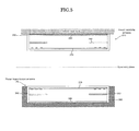
- FIG. 4 is an exploded perspective view of the power receiving antenna 210 used in the electric power transmission system according to the embodiment of the present invention.
- FIG. 5 is a schematic cross-sectional view illustrating how power is transmitted between the antennas in power transmission of the embodiment of the present invention.
- a coil body 270 an example of a coil that is in the shape of a rectangular flat plate will be described.
- the antennas of the present invention are not limited to a coil of such a shape.
- a coil body 270 that is in the shape of a circular flat plate or the like may also be available.
- Such a coil body 270 functions as a magnetic resonance antenna section of the power receiving antenna 210.
- the "magnetic resonance antenna section" includes not only an inductance component of the coil body 270 but also a capacitance component based on floating capacitance thereof or a capacitance component based on a capacitor that is intentionally added.
- a coil case 260 is used to house the coil body 270, which includes an inductance component of the power receiving antenna 210.
- the coil case 260 is made of, for example, resin such as polycarbonate, and is in the shape of a box with an opening. From each side of a rectangular bottom plate section 261 of the coil case 260, a side plate section 262 is provided in such a way as to extend in a direction perpendicular to the bottom plate section 261. On an upper side of the coil case 260, an upper opening 263 is formed in such a way as to be surrounded by the side plate sections 262.
- the power receiving antenna 210 packaged in the coil case 260 is mounted on a vehicle's main body section at the upper opening 263's side.
- any conventional, well-known method may be used.
- a flange member or the like may be provided around the upper opening 263.
- the coil body 270 includes a base 271, which is made of glass epoxy and is in the shape of a rectangular flat plate, and a conductive section 272, which is formed on the base 271 and is in a spiral shape. To an inner peripheral-side first end portion 273 and outer peripheral-side second end portion 274 of the spirally shaped conductive section 272, conductive lines (not shown) are electrically connected. Therefore, the electric power received by the power receiving antenna 210 can be introduced to the rectifying section 202.
- the coil body 270 is placed on the rectangular bottom plate section 261 of the coil case 260, and is fixed to the bottom plate section 261 through a suitable fixing means.
- a magnetic shield body 280 is a plate-like magnetic member having a hollow section 285. It is desirable that the magnetic shield body 280 be made of a material that is large in specific resistance and magnetic permeability and small in magnetic hysteresis; for example, magnetic material such as ferrite may be used.
- the magnetic shield body 280 is fixed to the coil case 260 through an appropriate means in such a way as to be disposed with some space above the coil body 270. Such a layout helps to increase the rate at which lines of magnetic force generated on the power transmission antenna 140's side are transmitted through the magnetic shield body 280, thereby reducing the impact of metal objects making up the vehicle's main body section on the lines of magnetic force during the transmission of electric power from the power transmission antenna 140 to the power receiving antenna 210.
- a metal body lid 290 that is in the shape of a rectangular flat plate is placed a predetermined distance above the shield body 280 in such a way as to cover the upper opening 263.
- any metal material may be used. According to the present embodiment, aluminum is used, for example.
- the magnetic shield body 280 is provided above the coil body 270. Therefore, even when the power receiving antenna 210 is mounted on the vehicle's bottom surface, the effects of metal objects and other components making up the vehicle's main body section are reduced, and the transmission of electric power can be performed efficiently.
- the above-described configuration of the power receiving antenna 210 is also applied to the power transmission antenna of the electric power transmission system 100.
- the power transmission antenna 140 is so formed as to have plane symmetry (mirror symmetry) with the power receiving antenna 210 with respect to a horizontal plane.
- a coil body 370 is disposed in a coil case 360, and a magnetic shield body 380 is provided a predetermined distance away from the coil body 370, and the coil case 160 is sealed with a metal body lid 390.
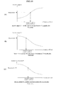
- FIG. 6 is a diagram showing the relationship between frequency and power transmission efficiency in the electric power transmission system of the present embodiment.
- FIG. 6A shows frequency characteristics of power transmission efficiency corresponding to a situation where the power receiving antenna 210 and the power transmission antenna 140 are optimally disposed (or a situation where the positional change is zero with the highest coupling coefficient). As shown in FIG. 6A , there are two frequencies that give two maximum values. Furthermore, there is one frequency that gives a minimum value therebetween. The extreme-value frequency that gives a maximum value of a lower frequency is defined as a first extreme-value frequency, and the extreme-value frequency that gives a maximum value of a higher frequency is defined as a second extreme-value frequency.
- the positional change between the power receiving antenna 210 and the power transmission antenna 140 becomes larger from FIG. 6A, FIG. 6B and FIG. 6C and then to FIG. 6D ; what is shown in the diagrams is frequency characteristics of power transmission efficiency during this process.
- FIG. 7 is a schematic diagram showing the state of current and electric fields at a first extreme-value frequency.
- the phase of current flowing through the power transmission antenna 140 is substantially equal to the phase of current flowing through the power receiving antenna 210.
- the vectors of magnetic fields are aligned at around a middle point of the power transmission antenna 140 and of the power receiving antenna 210. This state is regarded as generating a magnetic wall whose magnetic field is perpendicular to a symmetry plane located between the power transmission antenna 140 and the power receiving antenna 210.
- FIG. 8 is a schematic diagram showing the state of current and electric fields at a second extreme-value frequency.
- the phase of current flowing through the power transmission antenna 140 is substantially opposite to the phase of current flowing through the power receiving antenna 210.
- the vectors of magnetic fields are aligned at around the symmetry plane of the power transmission antenna 140 and of the power receiving antenna 210. This state is regarded as generating an electric wall whose magnetic field is horizontal to the symmetry plane located between the power transmission antenna 140 and the power receiving antenna 210.
- an extreme-value frequency at which an electric wall is generated at a symmetry plane between the power transmission antenna 140 and the power receiving antenna 210 is selected when there are two frequencies, i.e., the first and second extreme-value frequencies, as frequencies giving extreme-values.
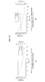
- FIG. 9 is a diagram showing characteristics at an extreme-value frequency (first extreme-value frequency) at which a magnetic wall emerges, among the extreme-value frequencies that give two extreme values.
- FIG. 9A is a diagram showing how voltage (V 1 ) and current (I 1 ) vary at the power transmission side when a change or variation of the load of the battery 240 (load) occurs.
- FIG. 9B is a diagram showing how voltage (V 3 ) and current (I 3 ) vary at the power receiving side when a change or variation of the load of the battery 240 (load) occurs. According to the characteristics shown in FIG. 9 , as the load of the battery 240 (load) at the power receiving side increases, the voltage rises.
- the power receiving antenna 210 seems like a constant current source.
- the power receiving antenna 210 works like a constant current source, if an emergency stop occurs due to trouble of the battery 240 or the like at the load side when the transmission of power is performed, the voltages of both end portions of the power receiving antenna 210 will rise.
- FIG. 10 is a diagram showing characteristics at an extreme-value frequency (second extreme-value frequency) at which an electric wall emerges, among the extreme-value frequencies that give two extreme values.
- FIG. 10A is a diagram showing how voltage (V 1 ) and current (I 1 ) vary at the power transmission side when a change or variation of the load of the battery 240 (load) occurs.
- FIG. 10B is a diagram showing how voltage (V 3 ) and current (I 3 ) vary at the power receiving side when a change or variation of the load of the battery 240 (load) occurs. According to the characteristics shown in FIG. 10 , as the load of the battery 240 (load) at the power receiving side increases, the current decreases.
- the power receiving antenna 210 seems like a constant voltage source.
- the voltages of both end portions of the power receiving antenna 210 will not rise. Therefore, in the electric power transmission system of the present invention, the voltage does not rise to a high level when the load plunges; the transmission of electric power can be performed in a stable manner.
- the charging circuit seems like a current source.
- the charging circuit seems like a voltage source.
- the characteristics of FIG. 10 are more preferred for the battery 240 (load) because the current decreases. Therefore, according to the present embodiment, when there are two frequencies, i.e., the first and second extreme-value frequencies, an extreme-value frequency at which an electric wall emerges at the symmetry plane between the power transmission antenna 140 and the power receiving antenna 210 is selected.
- the above electric power transmission system of the present invention can quickly determine an optimum frequency for the transmission of electric power, and therefore can perform the transmission of electric power efficiently and in a short time.
- the charging circuit seems like a voltage source. Therefore, the advantage is that, as the output to the battery 240 changes due to charging control, the output of the inverter unit 130 rises or falls accordingly, and therefore it is easy to handle. Moreover, when an emergency shutdown of the charging unit 230 occurs, the power to be supplied is automatically minimized. Therefore, there is no need for additional equipment.
- the rectifying unit 220 seems like a voltage source. Therefore, the advantage is that, as the output to the battery 240 changes due to charging control, the output of the rectifying and step-up unit 120 rises or falls accordingly, and therefore it is easy to handle. Moreover, when an emergency shutdown of the charging unit 230 occurs, the power to be supplied is automatically minimized. Therefore, there is no need for additional equipment.
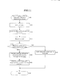
- FIG. 11 is a diagram showing a flowchart of a coupling coefficient calculation/ frequency determination process in the electric power transmission system according to the embodiment of the present invention.
- the coupling coefficient calculation/ frequency determination process starts.
- the power transmission control unit 150 sets the rectifying and step-up unit 120 in such a way that a predetermined output value (e.g., 1.5 kW) is output.
- a drive frequency of the inverter unit 130 is set to a coupling coefficient detection frequency.
- the coupling coefficient detection frequency will be described.
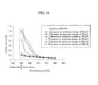
- FIG. 12 is a diagram illustrating the coupling coefficient detection frequency in the electric power transmission system 100 according to the embodiment of the present invention.
- the horizontal axis represents the drive frequency of the inverter unit 130
- the vertical axis represents current I 1 , which is input to the inverter unit 130.
- the drive frequency 480 kHz is a frequency (See FIG. 6A ) near the second extreme-value frequency
- 460 kHz is near an intermediate frequency (See FIG. 6A ) between a frequency that gives a minimum value of efficiency and the frequency of the second extreme-value frequency.
- the latter frequency 460 kHz
- a frequency between the frequency with maximum transmission efficiency between the power transmission antenna 140 and the power receiving antenna 210 and the frequency with minimum transmission efficiency is selected.
- the current I 1 of the inverter unit 130 is measured.
- the predetermined current value is a current value at which the positional change (which is proportional to the inverse of the coupling coefficient) cannot be determined.
- the predetermined current value may be set to about 0.2 A.
- step S104 determines whether the transmission of electric power is impossible because the positional change (which is proportional to the inverse of the coupling coefficient) is too large.
- step S105 based on the measured current value (current I 1 ), the coupling coefficient is calculated by referencing the first table in the data table 151. As described above, in the first table, the relationship between the current flowing through the inverter unit 130 and the coupling coefficient between the power transmission antenna 140 and the power receiving antenna 210 is stored.
- FIG. 13 is a diagram showing one example of the data table. By using the data table of FIG. 13 , for example, if the measured current value (current I 1 ) is 0.6 A, it is possible to calculate a positional change of 12 cm.
- the frequency for carrying out actual transmission of electric power is determined based on the calculated coupling coefficient.
- the relationship between the coupling coefficient between the power transmission antenna 140 and the power receiving antenna 210 and the transmission frequency is stored.
- FIG. 14 is a diagram showing one example of the data table.
- the frequency determined based on FIG. 14 is a frequency that is near the second extreme-value frequency and at which an electric wall emerges; to the battery 240, the power receiving antenna 210 seems like a constant voltage source.
- the voltages of both end portions of the power receiving antenna 210 will not rise. Therefore, in the electric power transmission system of the present invention, the voltage does not rise to a high level when the load plunges; the transmission of electric power can be performed in a stable manner.
- step S108 the flow of the coupling coefficient calculation/ frequency determination process comes to an end.
- the control unit uses a specific frequency to drive the inverter unit 130, and measures the current flowing through the inverter unit 130, and calculates the coupling coefficient between the power transmission antenna 140 and the power receiving antenna 210 based on the measured current and the data table 151. Therefore, the electric power transmission system of the present invention can properly recognize the positional change between the power transmission antenna 140 and the power receiving antenna 210 based on the coupling coefficient, and thereby efficiently carry out the transmission of electric power.
- the control unit is designed to determine the transmission frequency for transmitting electric energy via electromagnetic fields from the power transmission antenna 140, from the coupling coefficient between the power transmission antenna 140 and the power receiving antenna 210, which is calculated by the calculation unit, and from the data table 151. Therefore, the electric power transmission system of the present invention can properly recognize, from the coupling coefficient, the positional change between the power transmission antenna 140 and the power receiving antenna 210. Thus, the electric power transmission system can select, based on the positional change, an appropriate frequency for the transmission of electric power, and thereby carry out the transmission of electric power efficiently.
- FIG. 15 is a diagram showing a flowchart of an electric power transmission process in the electric power transmission system according to the embodiment of the present invention. The flowchart is executed by the power transmission control unit 150.
- FIG. 14 is a diagram showing a charging profile of the battery 240.
- the charging profile is one example of charging profiles for the battery 240. In charging the battery 240, other profiles may be used.
- the charging profile shown in FIG. 14 starts to be used when the amount of electricity stored in the battery 240 is almost zero.
- constant current charging CC control
- I const constant level of current
- CV control constant voltage charging
- the flowchart of the electric power transmission process shown in FIG. 15 is established based on such a charging profile.
- the electric power transmission process starts. Then, at step S201, the power transmission control unit 150 sets the rectifying and step-up unit 120 in such a way that the target output value becomes, for example. 1.5 kW.
- the drive frequency of the inverter unit 130 is set to the optimum frequency that is determined during the previous frequency determination process.
- the transmission of electric power is carried out.
- the output power is measured based on the voltage V 2 and current I 2 that are output from the inverter unit 130.
- the power receiving-side charging unit 230 is performing a charging operation with a constant current.
- impedance Z N is equal to Z CC when viewed from the power transmission side.
- the power receiving-side charging unit 230 starts a charging operation with a constant voltage.
- impedance Z N is equal to Z CV when viewed from the power transmission side. If the impedance is changed as described above, the power output from the inverter unit 130 becomes smaller than the predetermined power.
- Step S205 is intended to detect such a change on the power receiving side.
- step S205 When the determination result at step S205 is NO, the process enters a return loop to step S203.
- the process proceeds to step S206, and the rectifying and step-up unit 120 is set in such a way that the output voltage to the inverter unit 130 remains unchanged.
- the transmission of electric power is carried out.
- the charging control unit 250 measures the current I 3 that is input to the battery 240.
- step S209 a determination is made as to whether or not the measured current I 3 becomes minimum current I min .
- the process enters a return loop to step S207.
- the determination result at step S209 is YES, the process of charging the battery 240 on the power receiving side is estimated to be finished. Therefore, the process proceeds to step S210 to stop the transmission of electric power, and the process ends at step S211.
- the control unit uses a specific frequency to drive the inverter unit, and measures the current flowing through the inverter unit, and calculates the coupling coefficient between the power transmission antenna and the power receiving antenna based on the measured current and the table. Therefore, the electric power transmission system of the present invention can properly recognize the positional change between the power transmission antenna and the power receiving antenna based on the coupling coefficient, and thereby efficiently carry out the transmission of electric power.
- the control unit is designed to determine the transmission frequency for transmitting electric energy via electromagnetic fields from the power transmission antenna, from the coupling coefficient between the power transmission antenna and the power receiving antenna, which is calculated by the calculation unit, and from the table. Therefore, the electric power transmission system of the present invention can properly recognize, from the coupling coefficient, the positional change between the power transmission antenna and the power receiving antenna. Thus, the electric power transmission system can select, based on the positional change, an appropriate frequency for the transmission of electric power, and thereby carry out the transmission of electric power efficiently.
- FIG. 17 is a diagram showing one example of a second data table in which the relationship between a coupling coefficient between the power transmission antenna 140 and the power receiving antenna 210 and the transmission frequency is stored; the second data table is used in an electric power transmission system 100 of this other embodiment.
- the data table can support a plurality of types of batteries 240. More specifically, the second data table of this other embodiment is a data table in which the relationship between the positional change (which is proportional to the inverse of the coupling coefficient) between the power transmission antenna 140 and the power receiving antenna 210, the transmission frequency, and the impedance of the battery 240 (load) is defined.
- a left data table encircled by dotted line is used in determining the frequency for the transmission of electric power.
- a right data table encircled by dotted line is used in determining the frequency for the transmission of electric power.
- An additional advantage is that the system can support a plurality of types of batteries 240.
- the power transmission control unit 150 inputs DC voltage of a specific voltage value to the inverter unit 130, and drives the inverter unit 130 at a specific frequency, and measures the current flowing through the inverter unit 130, and calculates, from the measured current and the first table, the coupling coefficient between the power transmission antenna 140 and the power receiving antenna 210.
- the coupling coefficient between the power transmission antenna 140 and the power receiving antenna 210 takes various values as parameters, for example, there is a relationship as shown in the image diagram of FIG. 18 between voltage value V 1 of DC voltage input to the inverter unit 130, current value I 1 , and drive frequency f of the inverter unit 130. That is, if the coupling coefficient between the antennas is changed in various ways, set (V 1 , I 1 , f) forms a predetermined plane in a coordinate system shown in FIG. 18 .
- FIG. 19 is a diagram showing an example of a table used in an electric power transmission system according to an embodiment of the present invention.
- FIG. 19A shows an example of the first table used in the first embodiment.
- FIG. 19B shows an example of a table (third table) that is used to calculate the coupling coefficient between the antennas, according to another embodiment.
- the relationship between voltage value V 1 of DC voltage input to the inverter unit 130 and the coupling coefficient between the power transmission antenna 140 and the power receiving antenna 210 is stored.
- the power transmission control unit 150 inputs DC voltage of a specific current value to the inverter unit 130, and drives the inverter unit 130 at a specific frequency, and measures the voltage flowing through the inverter unit 130, and calculates, from the measured voltage and the table (third table) shown in FIG. 19B , the coupling coefficient between the power transmission antenna 140 and the power receiving antenna 210.
- FIG. 19C shows an example of a table (fourth table) that is used to calculate the coupling coefficient between the antennas, according to another embodiment.
- the power transmission control unit 150 acquires the drive frequency of the inverter unit 130 when inputting DC voltage of specific voltage and current values to the inverter unit 130, and calculates, from the acquired frequency and the table (fourth table), the coupling coefficient between the power transmission antenna 140 and the power receiving antenna 210.
- the electric power transmission system can properly recognize, from the coupling coefficient, the positional change between the power transmission antenna 140 and the power receiving antenna 210, and thereby efficiently carry out the transmission of electric power.
- the electric power transmission system of the present invention is suitably used in a system that charges vehicles, such as electric vehicles (EV) or hybrid electric vehicles (HEV), which have rapidly become popular in recent years.
- a system that charges vehicles, such as electric vehicles (EV) or hybrid electric vehicles (HEV), which have rapidly become popular in recent years.
- EV electric vehicles
- HEV hybrid electric vehicles
- Such an electric power transmission system is provided in a parking space where a vehicle can be stopped.
- a user of the vehicle parks the vehicle in the parking space in which the electric power transmission system is provided.
- a power receiving antenna mounted on the vehicle receives electric power from the electric power transmission system.
- the frequency for carrying out the transmission of electric power is not necessarily a frequency that yields maximum efficiency based on a coupling coefficient (a positional change between the antennas) between the current power transmission antenna and power receiving antenna. In this case, the problem is that the transmission of electric power cannot be performed efficiently.
- the control unit uses a specific frequency to drive the inverter unit, and measures the current flowing through the inverter unit, and calculates the coupling coefficient between the power transmission antenna and the power receiving antenna based on the measured current and the table. Therefore, the electric power transmission system of the present invention can properly recognize the positional change between the power transmission antenna and the power receiving antenna based on the coupling coefficient, and thereby efficiently carry out the transmission of electric power. Therefore, the system is very high in industrial applicability.
Landscapes
- Engineering & Computer Science (AREA)
- Power Engineering (AREA)
- Transportation (AREA)
- Mechanical Engineering (AREA)
- Computer Networks & Wireless Communication (AREA)
- Charge And Discharge Circuits For Batteries Or The Like (AREA)
- Electric Propulsion And Braking For Vehicles (AREA)
Abstract
Description
- The present invention relates to a wireless electric power transmission system that uses a magnetic resonance antenna of a magnetic resonance method.
- In recent years, development of technology for wirelessly transmitting electric power (electric energy) without using power supply cords and the like has become popular. Among methods for wirelessly transmitting electric power, the technique called a magnetic resonance method is gaining particular attention. The magnetic resonance method was proposed by a research group at the Massachusetts Institute of Technology in 2007. The related technology is disclosed in Patent Document 1 (
JP2009-501510A - In a wireless electric power transmission system of the magnetic resonance method, a resonance frequency of a power transmission antenna is equal to a resonance frequency of a power receiving antenna. Therefore, from the power transmission antenna to the power receiving antenna, energy can be efficiently transmitted. One of major features is that the power transmission distance can be from several tens of centimeters to several meters.
- In the above wireless electric power transmission system of the magnetic resonance method, if one of the antennas is mounted on a moving object such as an electric vehicle, the arrangement of the antennas would change each time the transmission of electric power is carried out. Accordingly, the frequency that gives an optimum electric power transmission efficiency would vary. Therefore, what is proposed is a technique for determining an optimum frequency for actual transmission of power by sweeping frequencies before the transmission of electric power takes place. For example, what is disclosed in Patent Document 2 (
JP2010-68657A - Patent Document 1:
JP2009-501510A - Patent Document 2:
JP2010-68657A - The electric power transmission system disclosed in
Patent Document 2 is expected to be used in a system that charges vehicles such as electric vehicles (EV). Such an electric power transmission system is provided in a parking space where a vehicle can be stopped. A user of the vehicle parks the vehicle in the parking space in which the electric power transmission system is provided. A power receiving antenna mounted on the vehicle receives electric power from the electric power transmission system. - When the vehicle is parked in the parking space, the relationship between the vehicle-mounted power receiving antenna and a parking space-side power transmission antenna is not always of the best transmission efficiency position (or the position where a maximum coupling coefficient between the power transmission antenna and the power receiving antenna is achieved; or, for example, if the power transmission antenna and the power receiving antenna are in the same shape and equal in size, the position is where a positional change in front-back and left-right directions is zero) . That is, the electric power transmission system of the prior art is just set to an intermediate frequency. That frequency is not necessarily a frequency that yields maximum efficiency based on a coupling coefficient (a positional change between the antennas) between the current power transmission antenna and power receiving antenna. In this case, the problem is that the transmission of electric power cannot be performed efficiently.
- To solve the above problem, according to the invention of claim 1, an electric power transmission system is characterized by including: an inverter unit that converts DC voltage to AC voltage of a predetermined frequency to output; a power transmission antenna to which AC voltage is input from the inverter unit; a control unit that controls a voltage value of DC voltage input to the inverter unit, and a frequency of AC voltage output by the inverter unit; and a power receiving antenna that faces the power transmission antenna and is for transmission of electric energy from the power transmission antenna via electromagnetic fields, wherein, based on current flowing through the inverter unit, a coupling coefficient between the power transmission antenna and the power receiving antenna is calculated.
- According to the invention of
claim 2, the electric power transmission system of claim 1 is characterized by including a table in which a relationship between current flowing through the inverter unit and a coupling coefficient between the power transmission antenna and the power receiving antenna is stored, wherein the control unit inputs DC voltage of a specific voltage value to the inverter unit, and drives the inverter unit at a specific frequency, and measures the current flowing through the inverter unit, and calculates, from the measured current and the table, the coupling coefficient between the power transmission antenna and the power receiving antenna. - According to the invention of claim 3, the electric power transmission system of
claim 2 is characterized in that, as the specific frequency, a frequency between a frequency that yields maximum transmission efficiency between the power transmission antenna and the power receiving antenna and a frequency that yields minimum transmission efficiency is selected. - According to the invention of
claim 4, an electric power transmission system is characterized by including: an inverter unit that converts DC voltage to AC voltage of a predetermined frequency to output; a power transmission antenna to which AC voltage is input from the inverter unit; a control unit that controls a current value of DC voltage input to the inverter unit, and a frequency of AC voltage output by the inverter unit; and a power receiving antenna that faces the power transmission antenna and is for transmission of electric energy from the power transmission antenna via electromagnetic fields, wherein, based on voltage of current flowing through the inverter unit, a coupling coefficient between the power transmission antenna and the power receiving antenna is calculated. - According to the invention of
claim 5, the electric power transmission system ofclaim 4 is characterized by including a table in which a relationship between a voltage value of DC voltage input to the inverter unit and a coupling coefficient between the power transmission antenna and the power receiving antenna is stored, wherein the control unit inputs DC voltage of a specific current value to the inverter unit, and drives the inverter unit at a specific frequency, and measures voltage of current flowing through the inverter unit, and calculates, from the measured voltage and the table, the coupling coefficient between the power transmission antenna and the power receiving antenna. - According to the invention of claim 6, an electric power transmission system is characterized by including: an inverter unit that converts DC voltage to AC voltage of a predetermined frequency to output; a power transmission antenna to which AC voltage is input from the inverter unit; a control unit that controls voltage and current values of DC voltage input to the inverter unit, and a frequency of AC voltage output by the inverter unit; a power receiving antenna that faces the power transmission antenna and is for transmission of electric energy from the power transmission antenna via electromagnetic fields; and a table in which a relationship between a drive frequency of the inverter unit and a coupling coefficient between the power transmission antenna and the power receiving antenna is stored, wherein, based on the drive frequency of the inverter unit, a coupling coefficient between the power transmission antenna and the power receiving antenna is calculated.
- According to the invention of claim 7, the electric power transmission system of claim 6 is characterized by including a table in which a relationship between a drive frequency of the inverter unit and a coupling coefficient between the power transmission antenna and the power receiving antenna is stored, wherein the control unit acquires the drive frequency of the inverter unit when inputting DC voltage of specific voltage and current values to the inverter unit, and calculates, from the acquired frequency and the table, the coupling coefficient between the power transmission antenna and the power receiving antenna.
- In the electric power transmission system of the present invention, the control unit uses a specific frequency to drive the inverter unit, and measures the current flowing through the inverter unit, and calculates the coupling coefficient between the power transmission antenna and the power receiving antenna based on the measured current and the table. Therefore, the electric power transmission system of the present invention can properly recognize the positional change between the power transmission antenna and the power receiving antenna based on the coupling coefficient, and thereby efficiently carry out the transmission of electric power.
-
-
FIG. 1 is a block diagram of an electric power transmission system according to an embodiment of the present invention. -
FIG. 2 is a diagram illustrating definitions of positional relationship between a power transmission antenna and a power receiving antenna in an electric power transmission system according to an embodiment of the present invention. -
FIG. 3 is a diagram showing an inverter unit of an electric power transmission system of an embodiment of the present invention. -
FIG. 4 is an exploded perspective view of a power receivingantenna 210 used in an electric power transmission system according to an embodiment of the present invention. -
FIG. 5 is a schematic cross-sectional view illustrating how power is transmitted between antennas in power transmission of an embodiment of the present invention. -
FIG. 6 is a diagram showing the relationship between frequency and power transmission efficiency. -
FIG. 7 is a schematic diagram showing the state of current and electric fields at a first extreme-value frequency. -
FIG. 8 is a schematic diagram showing the state of current and electric fields at a second extreme-value frequency. -
FIG. 9 is a diagram showing characteristics at an extreme-value frequency (first frequency) at which a magnetic wall emerges, among the extreme-value frequencies that give two extreme values. -
FIG. 10 is a diagram showing characteristics at an extreme-value frequency (second frequency) at which an electric wall emerges, among the extreme-value frequencies that give two extreme values. -
FIG. 11 is a diagram showing a flowchart of a coupling coefficient calculation/frequency determination process in an electric power transmission system according to an embodiment of the present invention. -
FIG. 12 is a diagram illustrating a coupling coefficient detection frequency in an electric power transmission system according to an embodiment of the present invention. -
FIG. 13 is a diagram showing one example of a data table in which the relationship between current flowing through aninverter unit 130 and a coupling coefficient between apower transmission antenna 140 and apower receiving antenna 210 is stored. -
FIG. 14 is a diagram showing one example of a data table in which the relationship between a coupling coefficient between apower transmission antenna 140 and apower receiving antenna 210 and a transmission frequency is stored. -
FIG. 15 is a diagram showing a flowchart of an electric power transmission process in an electric power transmission system according to an embodiment of the present invention. -
FIG. 16 is a diagram showing a charging profile of a battery in an electric power transmission system according to an embodiment of the present invention. -
FIG. 17 is a diagram showing one example of a data table in which the relationship between a coupling coefficient between apower transmission antenna 140 and apower receiving antenna 210 and a transmission frequency is stored. -
FIG. 18 is a diagram of an image of a set (V1, I1, f) when a coupling coefficient between antennas is changed. -
FIG. 19 is a diagram showing an example of a table used in an electric power transmission system according to an embodiment of the present invention. - Hereinafter, an embodiment of the present invention will be described with reference to the accompanying drawings.
FIG. 1 is a block diagram of an electric power transmission system according to an embodiment of the present invention.FIG. 2 is a schematic diagram showing an example in which an electricpower transmission system 100 of the embodiment of the present invention is mounted on a vehicle. The electricpower transmission system 100 of the present invention is suitably used in a system that charges vehicle-mounted batteries, such as those of an electric vehicle (EV) or a hybrid electric vehicle (HEV), for example. For that purpose, on a bottom portion of a vehicle, a power receivingantenna 210 is placed to make it possible to receive electric power. - In the electric
power transmission system 100 of the present embodiment, electric power is transmitted to the above vehicle in a non-contact manner. Thepower transmission system 100 is therefore provided in a parking space where the vehicle can be stopped. In the parking space, which is a vehicle-charging space, apower transmission antenna 140 and other components of the electricpower transmission system 100 of the present embodiment are buried under the ground. A user of the vehicle parks the vehicle in the parking space in which the electric power transmission system of the present embodiment is provided. Electric energy (electric power) is transmitted from thepower transmission antenna 140 to thepower receiving antenna 210, which is mounted on the vehicle, via electromagnetic fields. - When the vehicle is parked in the parking space, the relationship between the vehicle-mounted
power receiving antenna 210 and thepower transmission antenna 140 is not always of the best transmission efficiency position (or the position where a maximum coupling coefficient between the power transmission antenna and the power receiving antenna is achieved; or, for example, if the power transmission antenna and the power receiving antenna are in the same shape and equal in size, the position is where a positional change in front-back and left-right directions is zero) . Therefore, the electricpower transmission system 100 of the present embodiment is configured in such a way as to recognize the positional relationship between thepower receiving antenna 210 and thepower transmission antenna 140 and then choose an optimum frequency for carrying out the electricpower transmission system 100 with maximum power transmission efficiency. -
FIG. 2 is a diagram illustrating definitions of positional relationship between thepower transmission antenna 140 and thepower receiving antenna 210 in the electric power transmission system according to the embodiment of the present invention. Both thepower transmission antenna 140 and thepower receiving antenna 210 are a substantially rectangular coil that is wound in a spiral shape. Under restriction, which means thepower receiving antenna 210 is mounted on the vehicle, the relative position of thepower transmission antenna 140 to thepower receiving antenna 210 where a coupling coefficient between thepower transmission antenna 140 and thepower receiving antenna 210 is maximized is defined as an optimum relative position. In this case, a positional change between thepower transmission antenna 140 and thepower receiving antenna 210 can be defined as a deviation from the optimum relative position. As the positional change between the antennas relative to the optimum relative position becomes larger, the coupling coefficient becomes smaller. - If the
power transmission antenna 140 and thepower receiving antenna 210 are equal in size and in the same shape, the coupling coefficient can be indirectly calculated by calculating the positional change between the antennas relative to the optimum relative position without calculating the coupling coefficient as an actual value. If thepower transmission antenna 140 and thepower receiving antenna 210 are different in size and in different shapes, the coupling coefficient can be indirectly calculated by calculating the positional change without calculating the coupling coefficient as an actual value in such cases as when the relationship between the positional change relative to the optimum relative position and the coupling coefficient is stored in advance for that size and shape. - In vehicle charging equipment (power transmission side), a rectifying and step-up
unit 120 includes a converter that converts AC voltage from an ACpower supply unit 110, such as commercial power supply, into a constant level of DC voltage; the rectifying and step-upunit 120 then steps up an output of the converter to a predetermined level of voltage. The settings of a voltage generated by the rectifying and step-upunit 120 can be controlled by a powertransmission control unit 150. - An
inverter unit 130 generates, from the DC voltage supplied from the rectifying and step-upunit 120, a predetermined level of AC voltage to input to thepower transmission antenna 140.FIG. 3 is a diagram showing the inverter unit of the electric power transmission system according to the embodiment of the present invention. As shown inFIG. 3 , for example, theinverter unit 130 includes four field-effect transistors (FET) QA to QD, which are connected in full-bridge configuration. - According to the present embodiment, between a connection portion T1, which is located between the switching elements QA and QB connected in series, and a connection portion T2, which is located between the switching elements QC and QD connected in series, the
power transmission antenna 140 is connected. When the switching elements QA and QD are ON, the switching elements QB and QC are OFF. When the witching elements QB and QC are ON, the switching elements QA and QD are OFF. As a result, a rectangular wave of AC voltage is generated between the connection portions T1 and T2. - To the switching elements QA to QD that make up the
above inverter unit 130, a drive signal is input from the powertransmission control unit 150. Moreover, the frequency for driving theinverter unit 130 can be controlled from the powertransmission control unit 150. - The output of the
above inverter unit 130 is supplied to thepower transmission antenna 140. Thepower transmission antenna 140 includes a coil having an inductance component (described later), and resonates with the vehicle-mountedpower receiving antenna 210, which is disposed in such a way as to face thepower transmission antenna 140. In this manner, electric energy output from thepower transmission antenna 140 can be transmitted to thepower receiving antenna 210. - Incidentally, when the output of the
inverter unit 130 is input to thepower transmission antenna 140, impedance matching may be carried out by a matching unit, which is not shown in the diagrams. The matching unit may include a passive element having a predetermined circuit constant. - In the electric power transmission system according to the embodiment of the present invention, when power is efficiently transmitted from the power transmission-side
power transmission antenna 140 of the electricpower transmission system 100 to the power receiving-sidepower receiving antenna 210, a resonance frequency of thepower transmission antenna 140 becomes equal to a resonance frequency of thepower receiving antenna 210. Therefore, from the power transmission antenna to the power receiving antenna, energy is efficiently transmitted. - Voltage V1 and current I1, which are input to the
inverter unit 130, and voltage V2 and current I2, which are output from theinverter unit 130, are measured by the powertransmission control unit 150. The powertransmission control unit 150 can acquire input power (W1 = V1×I1), which is input to theinverter unit 130, and output power (W2 = V2×I2), which is output from theinverter unit 130, from the measured voltage V1 and current I1 and the measured voltage V2 and current I2. The powertransmission control unit 150 uses the measured values to control the voltage value of DC voltage and current value input to theinverter unit 130. - The power
transmission control unit 150 includes a general-purpose information processing unit that includes a CPU, a ROM, which keeps programs that run on the CPU, a RAM, which serves as a work area for the CPU, and the like. The powertransmission control unit 150 can calculate the efficiency (W1/W2) of theinverter unit 130 from the acquired input power (W1) and output power (W2), and the like. - A data table 151 of the power
transmission control unit 150 includes a first table, in which the relationship between the current flowing through theinverter unit 130 and a coupling efficient between thepower transmission antenna 140 and the power receiving antenna 210 (which is inversely proportional to the positional change between the antennas) is stored; and a second table, in which the relationship between the positional change between thepower transmission antenna 140 and thepower receiving antenna 210 and a transmission frequency is stored. The powertransmission control unit 150 references a measured value that is input and the tables before carrying out control during the transmission of electric power. - The power
transmission control unit 150 carries out actual transmission of charging power by controlling the voltage of DC voltage output by the rectifying and step-upunit 120 and the frequency of AC voltage output by theinverter unit 130. - A communication unit 157 wirelessly communicates with a vehicle-
side communication unit 257 so the transmitting and receiving of data is possible between the power transmission side and the vehicle. The data received by the communication unit 157 is transferred to the powertransmission control unit 150. The powertransmission control unit 150 is able to transmit predetermined information to the vehicle side via the communication unit 157. - The configuration of the electric
power transmission system 100 provided on the vehicle side will be described. In the vehicle's power receiving-side system, thepower receiving antenna 210 is designed to resonate with thepower transmission antenna 140 to receive electric energy output from thepower transmission antenna 140. - The AC power received by the
power receiving antenna 210 is rectified by a rectifyingunit 220. The rectified power is accumulated in abattery 240 through acharging unit 230. The chargingunit 230 controls a process of charging thebattery 240 on the basis of a command from a chargingcontrol unit 250. Incidentally, in the present embodiment, thebattery 240 is used as a load of the power receiving-side system, and an example of charging the battery is explained. However, another load may be used as the load of the power receiving-side system. - Voltage V3 and current I3, which are input to the
battery 240 from the chargingunit 230, are measured by the chargingcontrol unit 250. Based on the measured voltage V3 and current I3, the chargingcontrol unit 250 controls the chargingunit 230, and thereby controls the process of charging thebattery 240 in such a way as to follow an appropriate charging profile of thebattery 240. The chargingunit 230 is able to select one of modes, i.e., constant current, constant output, or constant voltage, to charge thebattery 240. - The charging
control unit 250 includes a general-purpose information processing unit that includes a CPU, a ROM, which keeps programs that run on the CPU, a RAM, which serves as a work area for the CPU, and the like. The chargingcontrol unit 250 works cooperatively with each of components connected to the chargingcontrol unit 250 shown in the diagrams. - In the charging
control unit 250, the charging profile of thebattery 240 is stored, and algorithm for letting the chargingcontrol unit 250 operate in accordance with the profile is stored, too. - The
communication unit 257 wirelessly communicates with the communication unit 157 of the power transmission side so the transmitting and receiving of data is possible between the power transmission-side system and the vehicle-side system. The data received by thecommunication unit 257 is transferred to the chargingcontrol unit 250. The chargingcontrol unit 250 is able to transmit predetermined data (e.g., data about voltage V3 and current I3 and the like) to the power transmission side via thecommunication unit 257. - An
interface unit 230 is provided in a driver seat portion of the vehicle. Theinterface unit 230 provides predetermined information and the like to a user (driver), or accepts a user's operation or input. Theinterface unit 230 includes a display device, buttons, a touch panel, a speaker, and the like. After a predetermined operation is performed by a user, operation data is transmitted from theinterface unit 230 to the chargingcontrol unit 250, which then processes the operation data. To present predetermined information to a user, from the chargingcontrol unit 250 to theinterface unit 230, display instruction data is transmitted to display the predetermined information. -
FIG. 4 is an exploded perspective view of thepower receiving antenna 210 used in the electric power transmission system according to the embodiment of the present invention.FIG. 5 is a schematic cross-sectional view illustrating how power is transmitted between the antennas in power transmission of the embodiment of the present invention. Incidentally, in the embodiment described below, as acoil body 270, an example of a coil that is in the shape of a rectangular flat plate will be described. However, the antennas of the present invention are not limited to a coil of such a shape. For example, acoil body 270 that is in the shape of a circular flat plate or the like may also be available. Such acoil body 270 functions as a magnetic resonance antenna section of thepower receiving antenna 210. The "magnetic resonance antenna section" includes not only an inductance component of thecoil body 270 but also a capacitance component based on floating capacitance thereof or a capacitance component based on a capacitor that is intentionally added. - A
coil case 260 is used to house thecoil body 270, which includes an inductance component of thepower receiving antenna 210. Thecoil case 260 is made of, for example, resin such as polycarbonate, and is in the shape of a box with an opening. From each side of a rectangularbottom plate section 261 of thecoil case 260, aside plate section 262 is provided in such a way as to extend in a direction perpendicular to thebottom plate section 261. On an upper side of thecoil case 260, anupper opening 263 is formed in such a way as to be surrounded by theside plate sections 262. Thepower receiving antenna 210 packaged in thecoil case 260 is mounted on a vehicle's main body section at theupper opening 263's side. In order to attach thecoil case 260 to the vehicle's main body section, any conventional, well-known method may be used. Incidentally, in order to make an improvement in the attachment of thecoil case 260 to the vehicle's main body section, a flange member or the like may be provided around theupper opening 263. - The
coil body 270 includes abase 271, which is made of glass epoxy and is in the shape of a rectangular flat plate, and aconductive section 272, which is formed on thebase 271 and is in a spiral shape. To an inner peripheral-sidefirst end portion 273 and outer peripheral-sidesecond end portion 274 of the spirally shapedconductive section 272, conductive lines (not shown) are electrically connected. Therefore, the electric power received by thepower receiving antenna 210 can be introduced to the rectifying section 202. Thecoil body 270 is placed on the rectangularbottom plate section 261 of thecoil case 260, and is fixed to thebottom plate section 261 through a suitable fixing means. - A
magnetic shield body 280 is a plate-like magnetic member having ahollow section 285. It is desirable that themagnetic shield body 280 be made of a material that is large in specific resistance and magnetic permeability and small in magnetic hysteresis; for example, magnetic material such as ferrite may be used. Themagnetic shield body 280 is fixed to thecoil case 260 through an appropriate means in such a way as to be disposed with some space above thecoil body 270. Such a layout helps to increase the rate at which lines of magnetic force generated on thepower transmission antenna 140's side are transmitted through themagnetic shield body 280, thereby reducing the impact of metal objects making up the vehicle's main body section on the lines of magnetic force during the transmission of electric power from thepower transmission antenna 140 to thepower receiving antenna 210. - As for the
upper opening 263 of thecoil case 260, ametal body lid 290 that is in the shape of a rectangular flat plate is placed a predetermined distance above theshield body 280 in such a way as to cover theupper opening 263. For themetal body lid 290, any metal material may be used. According to the present embodiment, aluminum is used, for example. - As described above, in the
power receiving antenna 210 of the present invention, themagnetic shield body 280 is provided above thecoil body 270. Therefore, even when thepower receiving antenna 210 is mounted on the vehicle's bottom surface, the effects of metal objects and other components making up the vehicle's main body section are reduced, and the transmission of electric power can be performed efficiently. - The above-described configuration of the
power receiving antenna 210 is also applied to the power transmission antenna of the electricpower transmission system 100. In this case, as shown inFIG. 5 , thepower transmission antenna 140 is so formed as to have plane symmetry (mirror symmetry) with thepower receiving antenna 210 with respect to a horizontal plane. - In the
power transmission antenna 140, as in the case of the power receiving side, acoil body 370 is disposed in acoil case 360, and amagnetic shield body 380 is provided a predetermined distance away from thecoil body 370, and the coil case 160 is sealed with ametal body lid 390. - The following describes frequency dependence of power transmission efficiency based on the positional relationship between the
power receiving antenna 210 andpower transmission antenna 140 of the electricpower transmission system 100 of the present embodiment that has the above-described configuration.FIG. 6 is a diagram showing the relationship between frequency and power transmission efficiency in the electric power transmission system of the present embodiment. -
FIG. 6A shows frequency characteristics of power transmission efficiency corresponding to a situation where thepower receiving antenna 210 and thepower transmission antenna 140 are optimally disposed (or a situation where the positional change is zero with the highest coupling coefficient). As shown inFIG. 6A , there are two frequencies that give two maximum values. Furthermore, there is one frequency that gives a minimum value therebetween. The extreme-value frequency that gives a maximum value of a lower frequency is defined as a first extreme-value frequency, and the extreme-value frequency that gives a maximum value of a higher frequency is defined as a second extreme-value frequency. - The positional change between the
power receiving antenna 210 and thepower transmission antenna 140 becomes larger fromFIG. 6A, FIG. 6B and FIG. 6C and then toFIG. 6D ; what is shown in the diagrams is frequency characteristics of power transmission efficiency during this process. - As shown in
FIGS. 6C and 6D , if there is one frequency that gives an extreme value of transmission efficiency, electric power can be transmitted with high transmission efficiency when the frequency of this extreme value is selected. If there are two frequencies, i.e., the first and second extreme-value frequencies, that give extreme values as shown inFIGS. 6A and 6B , an extreme-value frequency at which an electric wall emerges at a symmetry plane between thepower transmission antenna 140 and thepower receiving antenna 210 is selected in the case of the present embodiment. - The concepts of electric and magnetic walls that emerge at a symmetry plane between the
power transmission antenna 140 and thepower receiving antenna 210 will be described. -
FIG. 7 is a schematic diagram showing the state of current and electric fields at a first extreme-value frequency. At the first extreme-value frequency, the phase of current flowing through thepower transmission antenna 140 is substantially equal to the phase of current flowing through thepower receiving antenna 210. The vectors of magnetic fields are aligned at around a middle point of thepower transmission antenna 140 and of thepower receiving antenna 210. This state is regarded as generating a magnetic wall whose magnetic field is perpendicular to a symmetry plane located between thepower transmission antenna 140 and thepower receiving antenna 210. -
FIG. 8 is a schematic diagram showing the state of current and electric fields at a second extreme-value frequency. At the second extreme-value frequency, the phase of current flowing through thepower transmission antenna 140 is substantially opposite to the phase of current flowing through thepower receiving antenna 210. The vectors of magnetic fields are aligned at around the symmetry plane of thepower transmission antenna 140 and of thepower receiving antenna 210. This state is regarded as generating an electric wall whose magnetic field is horizontal to the symmetry plane located between thepower transmission antenna 140 and thepower receiving antenna 210. - As for the concept of the electric and magnetic walls and other things described above, what is described in the following documents and the like is adopted herein: Takehiro Imura, Youich Hori, "Transmission technology with electromagnetic field resonant coupling", IEEJ Journal, Vol.129, No.7, 2009, and Takehiro Imura, Hiroyuki Okabe, Toshiyuki Uchida, Youich Hori, "Research on magnetic field coupling and electric field coupling of non-contact power transmission in terms of equivalent circuits", IEEJ Trans.IA, Vol.130, No.1, 2010.
- In the case of the present invention, the following describes the reason why an extreme-value frequency at which an electric wall is generated at a symmetry plane between the
power transmission antenna 140 and thepower receiving antenna 210 is selected when there are two frequencies, i.e., the first and second extreme-value frequencies, as frequencies giving extreme-values. -
FIG. 9 is a diagram showing characteristics at an extreme-value frequency (first extreme-value frequency) at which a magnetic wall emerges, among the extreme-value frequencies that give two extreme values.FIG. 9A is a diagram showing how voltage (V1) and current (I1) vary at the power transmission side when a change or variation of the load of the battery 240 (load) occurs.FIG. 9B is a diagram showing how voltage (V3) and current (I3) vary at the power receiving side when a change or variation of the load of the battery 240 (load) occurs. According to the characteristics shown inFIG. 9 , as the load of the battery 240 (load) at the power receiving side increases, the voltage rises. - At the above-described frequency at which the magnetic wall emerges, when seen from the
battery 240's side, thepower receiving antenna 210 seems like a constant current source. At the frequency at which thepower receiving antenna 210 works like a constant current source, if an emergency stop occurs due to trouble of thebattery 240 or the like at the load side when the transmission of power is performed, the voltages of both end portions of thepower receiving antenna 210 will rise. -
FIG. 10 is a diagram showing characteristics at an extreme-value frequency (second extreme-value frequency) at which an electric wall emerges, among the extreme-value frequencies that give two extreme values.FIG. 10A is a diagram showing how voltage (V1) and current (I1) vary at the power transmission side when a change or variation of the load of the battery 240 (load) occurs.FIG. 10B is a diagram showing how voltage (V3) and current (I3) vary at the power receiving side when a change or variation of the load of the battery 240 (load) occurs. According to the characteristics shown inFIG. 10 , as the load of the battery 240 (load) at the power receiving side increases, the current decreases. - At the above-described frequency at which the electric wall emerges, when seen from the
battery 240's side, thepower receiving antenna 210 seems like a constant voltage source. At the frequency at which thepower receiving antenna 210 works like a constant voltage source, if an emergency stop occurs due to trouble of thebattery 240 or the like at the load side when the transmission of power is performed, the voltages of both end portions of thepower receiving antenna 210 will not rise. Therefore, in the electric power transmission system of the present invention, the voltage does not rise to a high level when the load plunges; the transmission of electric power can be performed in a stable manner. - According to the characteristics of
FIG. 9 , to the power receiving-side battery 240 (load), the charging circuit seems like a current source. According to the characteristics ofFIG. 10 , to the power receiving-side battery 240 (load), the charging circuit seems like a voltage source. As the load increases, the characteristics ofFIG. 10 are more preferred for the battery 240 (load) because the current decreases. Therefore, according to the present embodiment, when there are two frequencies, i.e., the first and second extreme-value frequencies, an extreme-value frequency at which an electric wall emerges at the symmetry plane between thepower transmission antenna 140 and thepower receiving antenna 210 is selected. - Even when there are two frequencies that give extreme values of transmission efficiency, the above electric power transmission system of the present invention can quickly determine an optimum frequency for the transmission of electric power, and therefore can perform the transmission of electric power efficiently and in a short time.
- If there are two frequencies that give two extreme values, and if an extreme-value frequency at which an electric wall emerges at the symmetry plane between the
power transmission antenna 140 and thepower receiving antenna 210 is selected, to the battery 240 (load), the charging circuit seems like a voltage source. Therefore, the advantage is that, as the output to thebattery 240 changes due to charging control, the output of theinverter unit 130 rises or falls accordingly, and therefore it is easy to handle. Moreover, when an emergency shutdown of the chargingunit 230 occurs, the power to be supplied is automatically minimized. Therefore, there is no need for additional equipment. - If there are two frequencies that give two extreme values, and if an extreme-value frequency at which an electric wall emerges at the symmetry plane between the
power transmission antenna 140 and thepower receiving antenna 210 is selected, to thecharging unit 230, the rectifyingunit 220 seems like a voltage source. Therefore, the advantage is that, as the output to thebattery 240 changes due to charging control, the output of the rectifying and step-upunit 120 rises or falls accordingly, and therefore it is easy to handle. Moreover, when an emergency shutdown of the chargingunit 230 occurs, the power to be supplied is automatically minimized. Therefore, there is no need for additional equipment. - If there are two frequencies that give two extreme values, and if an extreme-value frequency at which a magnetic wall emerges at the symmetry plane between the
power transmission antenna 140 and thepower receiving antenna 210 is selected, it is necessary to control the supplied power when the output is lowered by the chargingunit 230. In this case, a communication means and a detection means are required, leading to an increase in cost. - The following describes, in more detail, a process of determining the frequency at the time of power transmission in the electric
power transmission system 100 of the present embodiment that has the above-described configuration.FIG. 11 is a diagram showing a flowchart of a coupling coefficient calculation/ frequency determination process in the electric power transmission system according to the embodiment of the present invention. - At step S100, the coupling coefficient calculation/ frequency determination process starts. At step S101, the power
transmission control unit 150 sets the rectifying and step-upunit 120 in such a way that a predetermined output value (e.g., 1.5 kW) is output. - At step S102, a drive frequency of the
inverter unit 130 is set to a coupling coefficient detection frequency. Here, the coupling coefficient detection frequency will be described.FIG. 12 is a diagram illustrating the coupling coefficient detection frequency in the electricpower transmission system 100 according to the embodiment of the present invention. - In the graph of
FIG. 12 , the horizontal axis represents the drive frequency of theinverter unit 130, and the vertical axis represents current I1, which is input to theinverter unit 130. As for the drive frequency, 480 kHz is a frequency (SeeFIG. 6A ) near the second extreme-value frequency, and 460 kHz is near an intermediate frequency (SeeFIG. 6A ) between a frequency that gives a minimum value of efficiency and the frequency of the second extreme-value frequency. In the electricpower transmission system 100 of the present embodiment, as the coupling coefficient detection frequency, the latter frequency (460 kHz), or a frequency between the frequency with maximum transmission efficiency between thepower transmission antenna 140 and thepower receiving antenna 210 and the frequency with minimum transmission efficiency, is selected. - The fact that the value of the current I1 in the
inverter unit 130 is sensitive to the positional change (which is proportional to the inverse of the coupling coefficient) between thepower transmission antenna 140 and thepower receiving antenna 210 is among the reasons why such frequency is selected as the coupling coefficient detection frequency. - At step S103, the current I1 of the
inverter unit 130 is measured. At step S104, a determination is made as to whether or not the following formula is satisfied: "Measured current value (current I1) < Predetermined current value". In this case, the predetermined current value is a current value at which the positional change (which is proportional to the inverse of the coupling coefficient) cannot be determined. For example, in the example shown inFIG. 12 , the predetermined current value may be set to about 0.2 A. - When the determination result at step S104 is YES, the process proceeds to step S107, and a user is notified through the
interface unit 230 of the fact that the transmission of electric power is impossible because the positional change (which is proportional to the inverse of the coupling coefficient) is too large. - When the determination result at step S104 is NO, the process proceeds to step S105. At step S105, based on the measured current value (current I1), the coupling coefficient is calculated by referencing the first table in the data table 151. As described above, in the first table, the relationship between the current flowing through the
inverter unit 130 and the coupling coefficient between thepower transmission antenna 140 and thepower receiving antenna 210 is stored.FIG. 13 is a diagram showing one example of the data table. By using the data table ofFIG. 13 , for example, if the measured current value (current I1) is 0.6 A, it is possible to calculate a positional change of 12 cm. - At step S106, by referencing the second table in the data table 151, the frequency for carrying out actual transmission of electric power is determined based on the calculated coupling coefficient. As described above, in the second table, the relationship between the coupling coefficient between the
power transmission antenna 140 and thepower receiving antenna 210 and the transmission frequency is stored.FIG. 14 is a diagram showing one example of the data table. By using the data table ofFIG. 14 , for example, if the positional change is 12 cm, it is possible to determine a frequency of 477 kHz for carrying out the transmission of electric power. Incidentally, the frequency determined based onFIG. 14 is a frequency that is near the second extreme-value frequency and at which an electric wall emerges; to thebattery 240, thepower receiving antenna 210 seems like a constant voltage source. At the frequency at which thepower receiving antenna 210 works like a constant voltage source, if an emergency stop occurs due to trouble of thebattery 240 or the like at the load side when the transmission of power is performed, the voltages of both end portions of thepower receiving antenna 210 will not rise. Therefore, in the electric power transmission system of the present invention, the voltage does not rise to a high level when the load plunges; the transmission of electric power can be performed in a stable manner. - At step S108, the flow of the coupling coefficient calculation/ frequency determination process comes to an end.
- As described above, in the electric power transmission system of the present invention, the control unit uses a specific frequency to drive the
inverter unit 130, and measures the current flowing through theinverter unit 130, and calculates the coupling coefficient between thepower transmission antenna 140 and thepower receiving antenna 210 based on the measured current and the data table 151. Therefore, the electric power transmission system of the present invention can properly recognize the positional change between thepower transmission antenna 140 and thepower receiving antenna 210 based on the coupling coefficient, and thereby efficiently carry out the transmission of electric power. - Moreover, in the electric power transmission system of the present invention, the control unit is designed to determine the transmission frequency for transmitting electric energy via electromagnetic fields from the
power transmission antenna 140, from the coupling coefficient between thepower transmission antenna 140 and thepower receiving antenna 210, which is calculated by the calculation unit, and from the data table 151. Therefore, the electric power transmission system of the present invention can properly recognize, from the coupling coefficient, the positional change between thepower transmission antenna 140 and thepower receiving antenna 210. Thus, the electric power transmission system can select, based on the positional change, an appropriate frequency for the transmission of electric power, and thereby carry out the transmission of electric power efficiently. - The following describes a process of actually transmitting charging power with an optimum frequency that is determined as described above.
FIG. 15 is a diagram showing a flowchart of an electric power transmission process in the electric power transmission system according to the embodiment of the present invention. The flowchart is executed by the powertransmission control unit 150. -
FIG. 14 is a diagram showing a charging profile of thebattery 240. The charging profile is one example of charging profiles for thebattery 240. In charging thebattery 240, other profiles may be used. - The charging profile shown in
FIG. 14 starts to be used when the amount of electricity stored in thebattery 240 is almost zero. According to this charging profile, at first, constant current charging (CC control) is carried out to charge thebattery 240 with a constant level of current Iconst. Then, after an end-portion voltage of thebattery 240 reaches Vf, constant voltage charging (CV control) is carried out in such a way as to keep a constant level of charging voltage. After the current that flows into thebattery 240 reaches Imin during the constant voltage charging, the charging comes to an end. - The flowchart of the electric power transmission process shown in
FIG. 15 is established based on such a charging profile. - At step S200, the electric power transmission process starts. Then, at step S201, the power
transmission control unit 150 sets the rectifying and step-upunit 120 in such a way that the target output value becomes, for example. 1.5 kW. - At step S202, the drive frequency of the
inverter unit 130 is set to the optimum frequency that is determined during the previous frequency determination process. At step S203, the transmission of electric power is carried out. - At step S204, the output power is measured based on the voltage V2 and current I2 that are output from the
inverter unit 130. - At step S205, a determination is made as to whether or not the measured output power is smaller than a predetermined power. When the
inverter unit 130 is capable of outputting the predetermined power, the power receiving-side charging unit 230 is performing a charging operation with a constant current. At that time, impedance ZN is equal to ZCC when viewed from the power transmission side. After the power receiving side shifts from constant output charging to constant voltage charging, the power receiving-side charging unit 230 starts a charging operation with a constant voltage. As a result, impedance ZN is equal to ZCV when viewed from the power transmission side. If the impedance is changed as described above, the power output from theinverter unit 130 becomes smaller than the predetermined power. Step S205 is intended to detect such a change on the power receiving side. - When the determination result at step S205 is NO, the process enters a return loop to step S203. When the determination result at step S205 is YES, the process proceeds to step S206, and the rectifying and step-up
unit 120 is set in such a way that the output voltage to theinverter unit 130 remains unchanged. - At step S207, the transmission of electric power is carried out. At step S208, the charging
control unit 250 measures the current I3 that is input to thebattery 240. - At step S209, a determination is made as to whether or not the measured current I3 becomes minimum current Imin. When the determination result at step S209 is NO, the process enters a return loop to step S207. When the determination result at step S209 is YES, the process of charging the
battery 240 on the power receiving side is estimated to be finished. Therefore, the process proceeds to step S210 to stop the transmission of electric power, and the process ends at step S211. - As described above, in the electric power transmission system of the present invention, the control unit uses a specific frequency to drive the inverter unit, and measures the current flowing through the inverter unit, and calculates the coupling coefficient between the power transmission antenna and the power receiving antenna based on the measured current and the table. Therefore, the electric power transmission system of the present invention can properly recognize the positional change between the power transmission antenna and the power receiving antenna based on the coupling coefficient, and thereby efficiently carry out the transmission of electric power.
- Moreover, in the electric power transmission system of the present invention, the control unit is designed to determine the transmission frequency for transmitting electric energy via electromagnetic fields from the power transmission antenna, from the coupling coefficient between the power transmission antenna and the power receiving antenna, which is calculated by the calculation unit, and from the table. Therefore, the electric power transmission system of the present invention can properly recognize, from the coupling coefficient, the positional change between the power transmission antenna and the power receiving antenna. Thus, the electric power transmission system can select, based on the positional change, an appropriate frequency for the transmission of electric power, and thereby carry out the transmission of electric power efficiently.
- Another embodiment of the present invention will be described. In this other embodiment, only the configuration of the second table is different, and the configuration of the rest of the system is the same as those described above.
FIG. 17 is a diagram showing one example of a second data table in which the relationship between a coupling coefficient between thepower transmission antenna 140 and thepower receiving antenna 210 and the transmission frequency is stored; the second data table is used in an electricpower transmission system 100 of this other embodiment. - The data table can support a plurality of types of
batteries 240. More specifically, the second data table of this other embodiment is a data table in which the relationship between the positional change (which is proportional to the inverse of the coupling coefficient) between thepower transmission antenna 140 and thepower receiving antenna 210, the transmission frequency, and the impedance of the battery 240 (load) is defined. - In this case, for example, if the impedance of the
battery 240 is (a), a left data table encircled by dotted line is used in determining the frequency for the transmission of electric power. If the impedance of thebattery 240 is (b), a right data table encircled by dotted line is used in determining the frequency for the transmission of electric power. - According to this other embodiment described above, the same advantageous effects as those of the previous embodiment can be achieved. An additional advantage is that the system can support a plurality of types of
batteries 240. - Another embodiment of the present invention will be described. In the first embodiment, in the first table, the relationship between the current flowing through the
inverter unit 130 and the coupling coefficient between thepower transmission antenna 140 and thepower receiving antenna 210 is stored; the powertransmission control unit 150 inputs DC voltage of a specific voltage value to theinverter unit 130, and drives theinverter unit 130 at a specific frequency, and measures the current flowing through theinverter unit 130, and calculates, from the measured current and the first table, the coupling coefficient between thepower transmission antenna 140 and thepower receiving antenna 210. - On the other hand, if the coupling coefficient between the
power transmission antenna 140 and thepower receiving antenna 210 takes various values as parameters, for example, there is a relationship as shown in the image diagram ofFIG. 18 between voltage value V1 of DC voltage input to theinverter unit 130, current value I1, and drive frequency f of theinverter unit 130. That is, if the coupling coefficient between the antennas is changed in various ways, set (V1, I1, f) forms a predetermined plane in a coordinate system shown inFIG. 18 . - Therefore, it is clear that, if the voltage value V1 and the drive frequency f are specific values and if the current value I1 is measured, in addition to that of the first embodiment, there are various ways to calculate the coupling coefficient from the first table in which the relationship between the measured current value I1 and the coupling coefficient between the antennas is defined.
-
FIG. 19 is a diagram showing an example of a table used in an electric power transmission system according to an embodiment of the present invention.FIG. 19A shows an example of the first table used in the first embodiment. -
FIG. 19B shows an example of a table (third table) that is used to calculate the coupling coefficient between the antennas, according to another embodiment. - According to this embodiment, as shown in
FIG. 19B , in the table, the relationship between voltage value V1 of DC voltage input to theinverter unit 130 and the coupling coefficient between thepower transmission antenna 140 and thepower receiving antenna 210 is stored. The powertransmission control unit 150 inputs DC voltage of a specific current value to theinverter unit 130, and drives theinverter unit 130 at a specific frequency, and measures the voltage flowing through theinverter unit 130, and calculates, from the measured voltage and the table (third table) shown inFIG. 19B , the coupling coefficient between thepower transmission antenna 140 and thepower receiving antenna 210. -
FIG. 19C shows an example of a table (fourth table) that is used to calculate the coupling coefficient between the antennas, according to another embodiment. - According to this embodiment, as shown in
FIG. 19C , in the table, the relationship between drive frequency f of theinverter unit 130 and the coupling coefficient between thepower transmission antenna 140 and thepower receiving antenna 210 is stored. The powertransmission control unit 150 acquires the drive frequency of theinverter unit 130 when inputting DC voltage of specific voltage and current values to theinverter unit 130, and calculates, from the acquired frequency and the table (fourth table), the coupling coefficient between thepower transmission antenna 140 and thepower receiving antenna 210. - Even in the other embodiments described above, the electric power transmission system can properly recognize, from the coupling coefficient, the positional change between the
power transmission antenna 140 and thepower receiving antenna 210, and thereby efficiently carry out the transmission of electric power. - The electric power transmission system of the present invention is suitably used in a system that charges vehicles, such as electric vehicles (EV) or hybrid electric vehicles (HEV), which have rapidly become popular in recent years. Such an electric power transmission system is provided in a parking space where a vehicle can be stopped. A user of the vehicle parks the vehicle in the parking space in which the electric power transmission system is provided. A power receiving antenna mounted on the vehicle receives electric power from the electric power transmission system. In a conventional system, the frequency for carrying out the transmission of electric power is not necessarily a frequency that yields maximum efficiency based on a coupling coefficient (a positional change between the antennas) between the current power transmission antenna and power receiving antenna. In this case, the problem is that the transmission of electric power cannot be performed efficiently.
- In the electric power transmission system of the present invention, the control unit uses a specific frequency to drive the inverter unit, and measures the current flowing through the inverter unit, and calculates the coupling coefficient between the power transmission antenna and the power receiving antenna based on the measured current and the table. Therefore, the electric power transmission system of the present invention can properly recognize the positional change between the power transmission antenna and the power receiving antenna based on the coupling coefficient, and thereby efficiently carry out the transmission of electric power. Therefore, the system is very high in industrial applicability.
-
- 100:
- Electric power transmission system
- 110:
- AC power supply unit
- 120:
- Rectifying and step-up unit
- 130:
- Inverter unit
- 140:
- Power transmission antenna
- 150:
- Power transmission control unit
- 151:
- Data table
- 157:
- Communication unit
- 210:
- Power receiving antenna
- 220:
- Rectifying unit
- 230:
- Charging unit
- 240:
- Battery
- 250:
- Charging control unit
- 255:
- Interface unit
- 257:
- Communication unit
- 260:
- Coil case
- 261:
- Bottom plate section
- 262:
- Side plate section
- 263:
- (Upper) opening
- 270:
- Coil body
- 271:
- Base
- 272:
- Conductive section
- 273:
- First end portion
- 274:
- Second end portion
- 280:
- Magnetic shield body
- 285:
- Hollow section
- 290:
- Metal body lid
- 360:
- Coil case
- 370:
- Coil body
- 380:
- Magnetic shield body
- 390:
- Metal body lid
Claims (7)
- An electric power transmission system, characterized by comprising:an inverter unit that converts DC voltage to AC voltage of a predetermined frequency to output;a power transmission antenna to which AC voltage is input from the inverter unit;a control unit that controls a voltage value of DC voltage input to the inverter unit, and a frequency of AC voltage output by the inverter unit; anda power receiving antenna that faces the power transmission antenna and is for transmission of electric energy from the power transmission antenna via electromagnetic fields, whereinbased on current flowing through the inverter unit, a coupling coefficient between the power transmission antenna and the power receiving antenna is calculated.
- The electric power transmission system according to claim 1, characterized by comprising
a table in which a relationship between current flowing through the inverter unit and a coupling coefficient between the power transmission antenna and the power receiving antenna is stored, wherein
the control unit inputs DC voltage of a specific voltage value to the inverter unit, and drives the inverter unit at a specific frequency, and measures the current flowing through the inverter unit, and calculates, from the measured current and the table, the coupling coefficient between the power transmission antenna and the power receiving antenna. - The electric power transmission system according to claim 2, characterized in that
as the specific frequency, a frequency between a frequency that yields maximum transmission efficiency between the power transmission antenna and the power receiving antenna and a frequency that yields minimum transmission efficiency is selected. - An electric power transmission system, characterized by comprising:an inverter unit that converts DC voltage to AC voltage of a predetermined frequency to output;a power transmission antenna to which AC voltage is input from the inverter unit;a control unit that controls a current value of DC voltage input to the inverter unit, and a frequency of AC voltage output by the inverter unit; anda power receiving antenna that faces the power transmission antenna and is for transmission of electric energy from the power transmission antenna via electromagnetic fields, whereinbased on voltage of current flowing through the inverter unit, a coupling coefficient between the power transmission antenna and the power receiving antenna is calculated.
- The electric power transmission system according to claim 4, characterized by comprising
a table in which a relationship between a voltage value of DC voltage input to the inverter unit and a coupling coefficient between the power transmission antenna and the power receiving antenna is stored, wherein
the control unit inputs DC voltage of a specific current value to the inverter unit, and drives the inverter unit at a specific frequency, and measures voltage of current flowing through the inverter unit, and calculates, from the measured voltage and the table, the coupling coefficient between the power transmission antenna and the power receiving antenna. - An electric power transmission system, characterized by comprising:an inverter unit that converts DC voltage to AC voltage of a predetermined frequency to output;a power transmission antenna to which AC voltage is input from the inverter unit;a control unit that controls voltage and current values of DC voltage input to the inverter unit, and a frequency of AC voltage output by the inverter unit;a power receiving antenna that faces the power transmission antenna and is for transmission of electric energy from the power transmission antenna via electromagnetic fields; anda table in which a relationship between a drive frequency of the inverter unit and a coupling coefficient between the power transmission antenna and the power receiving antenna is stored, whereinbased on the drive frequency of the inverter unit, a coupling coefficient between the power transmission antenna and the power receiving antenna is calculated.
- The electric power transmission system according to claim 6, characterized by comprising
a table in which a relationship between a drive frequency of the inverter unit and a coupling coefficient between the power transmission antenna and the power receiving antenna is stored, wherein
the control unit acquires the drive frequency of the inverter unit when inputting DC voltage of specific voltage and current values to the inverter unit, and calculates, from the acquired frequency and the table, the coupling coefficient between the power transmission antenna and the power receiving antenna.
Applications Claiming Priority (2)
| Application Number | Priority Date | Filing Date | Title |
|---|---|---|---|
| JP2012078544A JP2013211932A (en) | 2012-03-30 | 2012-03-30 | Power transmission system |
| PCT/JP2012/083700 WO2013145488A1 (en) | 2012-03-30 | 2012-12-26 | Power transmission system |
Publications (2)
| Publication Number | Publication Date |
|---|---|
| EP2833509A1 true EP2833509A1 (en) | 2015-02-04 |
| EP2833509A4 EP2833509A4 (en) | 2015-12-23 |
Family
ID=49258817
Family Applications (1)
| Application Number | Title | Priority Date | Filing Date |
|---|---|---|---|
| EP12873131.2A Withdrawn EP2833509A4 (en) | 2012-03-30 | 2012-12-26 | Power transmission system |
Country Status (5)
| Country | Link |
|---|---|
| US (1) | US20150048688A1 (en) |
| EP (1) | EP2833509A4 (en) |
| JP (1) | JP2013211932A (en) |
| CN (1) | CN104170209A (en) |
| WO (1) | WO2013145488A1 (en) |
Cited By (7)
| Publication number | Priority date | Publication date | Assignee | Title |
|---|---|---|---|---|
| WO2015075514A1 (en) * | 2013-11-20 | 2015-05-28 | Toyota Jidosha Kabushiki Kaisha | Contactless power transfer system, charging station, and vehicle |
| EP3157136A1 (en) * | 2015-10-02 | 2017-04-19 | Panasonic Intellectual Property Management Co., Ltd. | Wireless power transmission system |
| EP3080894A4 (en) * | 2013-12-03 | 2017-06-07 | Utah State University | Determining physical alignment between magnetic couplers |
| US10284028B2 (en) | 2016-05-27 | 2019-05-07 | Wireless Advanced Vehicle Electrification, Inc. | Checking alignment of inductive charge pads in motion |
| US11437855B2 (en) | 2017-12-22 | 2022-09-06 | Wireless Advanced Vehicle Electrification, Llc | Wireless power transfer pad with multiple windings and magnetic pathway between windings |
| US11437854B2 (en) | 2018-02-12 | 2022-09-06 | Wireless Advanced Vehicle Electrification, Llc | Variable wireless power transfer system |
| US11462943B2 (en) | 2018-01-30 | 2022-10-04 | Wireless Advanced Vehicle Electrification, Llc | DC link charging of capacitor in a wireless power transfer pad |
Families Citing this family (19)
| Publication number | Priority date | Publication date | Assignee | Title |
|---|---|---|---|---|
| KR101697418B1 (en) | 2012-05-09 | 2017-01-17 | 도요타지도샤가부시키가이샤 | Vehicle |
| JP5988210B2 (en) * | 2012-08-31 | 2016-09-07 | 株式会社エクォス・リサーチ | Power transmission system |
| JP5988211B2 (en) * | 2012-09-28 | 2016-09-07 | 株式会社エクォス・リサーチ | Power transmission system |
| JP2014192939A (en) * | 2013-03-26 | 2014-10-06 | Panasonic Corp | Power supply apparatus, power receiver unit and power supply system |
| JP6124119B2 (en) * | 2013-03-29 | 2017-05-10 | パナソニックIpマネジメント株式会社 | Power feeding device and power receiving device |
| JP2014204603A (en) * | 2013-04-08 | 2014-10-27 | ソニー株式会社 | Power feeding apparatus and power feeding system |
| JP2015012748A (en) * | 2013-07-01 | 2015-01-19 | パナソニックIpマネジメント株式会社 | Power feeding apparatus and frequency characteristic acquisition method |
| WO2016125725A1 (en) * | 2015-02-02 | 2016-08-11 | 株式会社村田製作所 | Electric current detection element and electrical power transmission system |
| JP5995022B1 (en) * | 2015-09-10 | 2016-09-21 | パナソニックIpマネジメント株式会社 | Wireless power transmission system and power transmission device |
| CN108473067A (en) * | 2015-12-28 | 2018-08-31 | 日本电产株式会社 | Movable body system |
| JPWO2017115625A1 (en) * | 2015-12-28 | 2018-10-18 | 日本電産株式会社 | Mobile system |
| JP6645241B2 (en) | 2016-02-16 | 2020-02-14 | 株式会社Ihi | Power transmission equipment |
| JP6754669B2 (en) * | 2016-10-31 | 2020-09-16 | 株式会社ダイヘン | Power supply side device and power supply system |
| BR112019016542B1 (en) | 2017-04-07 | 2023-12-26 | Guangdong Oppo Mobile Telecommunications Corp., Ltd | WIRELESS CHARGING DEVICE, DEVICE TO BE CHARGED AND METHOD FOR CONTROLING A WIRELESS CHARGING DEVICE |
| US10734847B2 (en) * | 2017-08-23 | 2020-08-04 | Apple Inc. | Wireless power system with coupling-coefficient-based coil selection |
| WO2019110141A1 (en) * | 2017-12-04 | 2019-06-13 | Sew-Eurodrive Gmbh & Co. Kg | System for contactless energy transmission, having multiple primary conductor sections and at least one mobile part, and corresponding method |
| EP3719956B1 (en) | 2018-05-15 | 2022-11-02 | Guangdong Oppo Mobile Telecommunications Corp., Ltd. | Device to be charged and wireless charging method and system |
| DE112019007146T5 (en) * | 2019-04-01 | 2021-12-16 | Mitsubishi Electric Corporation | WIRELESS ENERGY SUPPLY SYSTEM AND ENERGY RECEIVER |
| JP2021002984A (en) | 2019-06-25 | 2021-01-07 | Tdk株式会社 | Wireless power transmission device and wireless power transmission system |
Family Cites Families (18)
| Publication number | Priority date | Publication date | Assignee | Title |
|---|---|---|---|---|
| WO1998034319A1 (en) * | 1997-02-03 | 1998-08-06 | Sony Corporation | Equipment and method for transmitting electric power |
| JP3884565B2 (en) * | 1998-05-21 | 2007-02-21 | 株式会社日立国際電気 | Non-contact IC card reader / writer device |
| CN101860089B (en) | 2005-07-12 | 2013-02-06 | 麻省理工学院 | Wireless non-radiative energy transfer |
| EP2078330A2 (en) * | 2006-10-25 | 2009-07-15 | Laszlo Farkas | High power wireless resonant energy transfer system transfers energy across an airgap |
| US8729734B2 (en) * | 2007-11-16 | 2014-05-20 | Qualcomm Incorporated | Wireless power bridge |
| JP5288958B2 (en) | 2008-09-11 | 2013-09-11 | 矢崎総業株式会社 | Wireless power transmission apparatus and resonance frequency adjustment method |
| US8400017B2 (en) * | 2008-09-27 | 2013-03-19 | Witricity Corporation | Wireless energy transfer for computer peripheral applications |
| JP5369693B2 (en) * | 2009-01-15 | 2013-12-18 | 日産自動車株式会社 | Non-contact power feeding device |
| JP5585098B2 (en) * | 2009-03-06 | 2014-09-10 | 日産自動車株式会社 | Non-contact power supply apparatus and method |
| JP5621203B2 (en) * | 2009-03-30 | 2014-11-12 | 富士通株式会社 | Wireless power supply system and wireless power supply method |
| JP5238884B2 (en) * | 2009-09-18 | 2013-07-17 | 株式会社東芝 | Wireless power transmission device |
| JP2011199975A (en) * | 2010-03-18 | 2011-10-06 | Nec Corp | Device, system and method for noncontact power transmission |
| US8145149B2 (en) * | 2010-06-17 | 2012-03-27 | R2 Semiconductor, Inc | Operating a voltage regulator at a switching frequency selected to reduce spurious signals |
| CN102474137B (en) * | 2010-06-30 | 2015-04-15 | 松下电器产业株式会社 | Electric power generator and electric power generating system |
| JP4996722B2 (en) * | 2010-06-30 | 2012-08-08 | 株式会社東芝 | Power transmission system and power transmission device |
| JP5093386B2 (en) * | 2010-08-25 | 2012-12-12 | 株式会社村田製作所 | Power transmission device and power transmission system |
| US9203380B2 (en) * | 2010-12-29 | 2015-12-01 | National Semiconductor Corporation | Resonance tuning |
| CN102347640B (en) * | 2011-06-09 | 2013-09-18 | 东南大学 | Wireless energy transmission device |
-
2012
- 2012-03-30 JP JP2012078544A patent/JP2013211932A/en active Pending
- 2012-12-26 EP EP12873131.2A patent/EP2833509A4/en not_active Withdrawn
- 2012-12-26 US US14/388,186 patent/US20150048688A1/en not_active Abandoned
- 2012-12-26 CN CN201280071301.2A patent/CN104170209A/en active Pending
- 2012-12-26 WO PCT/JP2012/083700 patent/WO2013145488A1/en active Application Filing
Cited By (11)
| Publication number | Priority date | Publication date | Assignee | Title |
|---|---|---|---|---|
| WO2015075514A1 (en) * | 2013-11-20 | 2015-05-28 | Toyota Jidosha Kabushiki Kaisha | Contactless power transfer system, charging station, and vehicle |
| EP3080894A4 (en) * | 2013-12-03 | 2017-06-07 | Utah State University | Determining physical alignment between magnetic couplers |
| US10075028B2 (en) | 2013-12-03 | 2018-09-11 | Utah State University | Determining physical alignment between magnetic couplers for wireless power transfer |
| EP3157136A1 (en) * | 2015-10-02 | 2017-04-19 | Panasonic Intellectual Property Management Co., Ltd. | Wireless power transmission system |
| US10418891B2 (en) | 2015-10-02 | 2019-09-17 | Panasonic Intellectual Property Management Co., Ltd. | Wireless power transmission system |
| US10284028B2 (en) | 2016-05-27 | 2019-05-07 | Wireless Advanced Vehicle Electrification, Inc. | Checking alignment of inductive charge pads in motion |
| US11437855B2 (en) | 2017-12-22 | 2022-09-06 | Wireless Advanced Vehicle Electrification, Llc | Wireless power transfer pad with multiple windings and magnetic pathway between windings |
| US11764613B2 (en) | 2017-12-22 | 2023-09-19 | Wireless Advanced Vehicle Electrification, Llc | Wireless power transfer pad with multiple windings and magnetic pathway between windings |
| US11462943B2 (en) | 2018-01-30 | 2022-10-04 | Wireless Advanced Vehicle Electrification, Llc | DC link charging of capacitor in a wireless power transfer pad |
| US11437854B2 (en) | 2018-02-12 | 2022-09-06 | Wireless Advanced Vehicle Electrification, Llc | Variable wireless power transfer system |
| US11824374B2 (en) | 2018-02-12 | 2023-11-21 | Wireless Advanced Vehicle Electrification, Llc | Variable wireless power transfer system |
Also Published As
| Publication number | Publication date |
|---|---|
| JP2013211932A (en) | 2013-10-10 |
| WO2013145488A1 (en) | 2013-10-03 |
| EP2833509A4 (en) | 2015-12-23 |
| US20150048688A1 (en) | 2015-02-19 |
| CN104170209A (en) | 2014-11-26 |
Similar Documents
| Publication | Publication Date | Title |
|---|---|---|
| EP2833509A1 (en) | Power transmission system | |
| EP2822147A1 (en) | Power transmission system | |
| EP2824797A1 (en) | Power transmission system | |
| WO2013002319A1 (en) | Electrical power transmission system | |
| JP5924496B2 (en) | Power transmission system | |
| US9537323B2 (en) | Contactless power supplying system with power limiting control | |
| EP2693600A1 (en) | Power transmission system | |
| EP2848453B1 (en) | Vehicle comprising power reception coil | |
| JP2013211933A (en) | Power transmission system | |
| US20130127409A1 (en) | Power transmission system, vehicle and power supply facility | |
| JP5915857B2 (en) | antenna | |
| KR20150015490A (en) | Vehicle | |
| JP2013038893A (en) | Power transmission system | |
| JP2013135491A (en) | Antenna | |
| JP2013132141A (en) | Power transmission system | |
| JP5930182B2 (en) | antenna | |
| JP2013212033A (en) | Power transmission system | |
| JP5888504B2 (en) | antenna | |
| JP2014093320A (en) | Power transmission system | |
| JP2014197935A (en) | Power transmission system | |
| JP2014093798A (en) | Power transmission system | |
| JP2014093321A (en) | Power transmission system | |
| JP2014093796A (en) | Power transmission system |
Legal Events
| Date | Code | Title | Description |
|---|---|---|---|
| PUAI | Public reference made under article 153(3) epc to a published international application that has entered the european phase |
Free format text: ORIGINAL CODE: 0009012 |
|
| 17P | Request for examination filed |
Effective date: 20140930 |
|
| AK | Designated contracting states |
Kind code of ref document: A1 Designated state(s): AL AT BE BG CH CY CZ DE DK EE ES FI FR GB GR HR HU IE IS IT LI LT LU LV MC MK MT NL NO PL PT RO RS SE SI SK SM TR |
|
| AX | Request for extension of the european patent |
Extension state: BA ME |
|
| DAX | Request for extension of the european patent (deleted) | ||
| RA4 | Supplementary search report drawn up and despatched (corrected) |
Effective date: 20151123 |
|
| RIC1 | Information provided on ipc code assigned before grant |
Ipc: H02J 17/00 20060101AFI20151117BHEP Ipc: H02J 5/00 20060101ALI20151117BHEP Ipc: H02J 7/02 20060101ALI20151117BHEP Ipc: B60L 11/18 20060101ALI20151117BHEP Ipc: H02M 7/5387 20070101ALI20151117BHEP |
|
| RIN1 | Information on inventor provided before grant (corrected) |
Inventor name: YAMAKAWA, HIROYUKI Inventor name: ITO, YASUO |
|
| STAA | Information on the status of an ep patent application or granted ep patent |
Free format text: STATUS: THE APPLICATION IS DEEMED TO BE WITHDRAWN |
|
| 18D | Application deemed to be withdrawn |
Effective date: 20160621 |