EP2833063A1 - Marine vessel, fuel-supplying device, and method for supplying liquefied fuel gas to main engine for propulsion - Google Patents
Marine vessel, fuel-supplying device, and method for supplying liquefied fuel gas to main engine for propulsion Download PDFInfo
- Publication number
- EP2833063A1 EP2833063A1 EP13768573.1A EP13768573A EP2833063A1 EP 2833063 A1 EP2833063 A1 EP 2833063A1 EP 13768573 A EP13768573 A EP 13768573A EP 2833063 A1 EP2833063 A1 EP 2833063A1
- Authority
- EP
- European Patent Office
- Prior art keywords
- lng
- fuel gas
- pressure
- fuel
- main engine
- Prior art date
- Legal status (The legal status is an assumption and is not a legal conclusion. Google has not performed a legal analysis and makes no representation as to the accuracy of the status listed.)
- Granted
Links
Images
Classifications
-
- B—PERFORMING OPERATIONS; TRANSPORTING
- B63—SHIPS OR OTHER WATERBORNE VESSELS; RELATED EQUIPMENT
- B63H—MARINE PROPULSION OR STEERING
- B63H21/00—Use of propulsion power plant or units on vessels
- B63H21/38—Apparatus or methods specially adapted for use on marine vessels, for handling power plant or unit liquids, e.g. lubricants, coolants, fuels or the like
-
- F—MECHANICAL ENGINEERING; LIGHTING; HEATING; WEAPONS; BLASTING
- F02—COMBUSTION ENGINES; HOT-GAS OR COMBUSTION-PRODUCT ENGINE PLANTS
- F02D—CONTROLLING COMBUSTION ENGINES
- F02D19/00—Controlling engines characterised by their use of non-liquid fuels, pluralities of fuels, or non-fuel substances added to the combustible mixtures
- F02D19/02—Controlling engines characterised by their use of non-liquid fuels, pluralities of fuels, or non-fuel substances added to the combustible mixtures peculiar to engines working with gaseous fuels
-
- F—MECHANICAL ENGINEERING; LIGHTING; HEATING; WEAPONS; BLASTING
- F02—COMBUSTION ENGINES; HOT-GAS OR COMBUSTION-PRODUCT ENGINE PLANTS
- F02D—CONTROLLING COMBUSTION ENGINES
- F02D19/00—Controlling engines characterised by their use of non-liquid fuels, pluralities of fuels, or non-fuel substances added to the combustible mixtures
- F02D19/06—Controlling engines characterised by their use of non-liquid fuels, pluralities of fuels, or non-fuel substances added to the combustible mixtures peculiar to engines working with pluralities of fuels, e.g. alternatively with light and heavy fuel oil, other than engines indifferent to the fuel consumed
-
- F—MECHANICAL ENGINEERING; LIGHTING; HEATING; WEAPONS; BLASTING
- F02—COMBUSTION ENGINES; HOT-GAS OR COMBUSTION-PRODUCT ENGINE PLANTS
- F02M—SUPPLYING COMBUSTION ENGINES IN GENERAL WITH COMBUSTIBLE MIXTURES OR CONSTITUENTS THEREOF
- F02M21/00—Apparatus for supplying engines with non-liquid fuels, e.g. gaseous fuels stored in liquid form
- F02M21/02—Apparatus for supplying engines with non-liquid fuels, e.g. gaseous fuels stored in liquid form for gaseous fuels
- F02M21/0218—Details on the gaseous fuel supply system, e.g. tanks, valves, pipes, pumps, rails, injectors or mixers
-
- F—MECHANICAL ENGINEERING; LIGHTING; HEATING; WEAPONS; BLASTING
- F23—COMBUSTION APPARATUS; COMBUSTION PROCESSES
- F23K—FEEDING FUEL TO COMBUSTION APPARATUS
- F23K5/00—Feeding or distributing other fuel to combustion apparatus
- F23K5/02—Liquid fuel
-
- B—PERFORMING OPERATIONS; TRANSPORTING
- B63—SHIPS OR OTHER WATERBORNE VESSELS; RELATED EQUIPMENT
- B63J—AUXILIARIES ON VESSELS
- B63J99/00—Subject matter not provided for in other groups of this subclass
- B63J2099/001—Burning of transported goods, e.g. fuel, boil-off or refuse
- B63J2099/003—Burning of transported goods, e.g. fuel, boil-off or refuse of cargo oil or fuel, or of boil-off gases, e.g. for propulsive purposes
-
- Y—GENERAL TAGGING OF NEW TECHNOLOGICAL DEVELOPMENTS; GENERAL TAGGING OF CROSS-SECTIONAL TECHNOLOGIES SPANNING OVER SEVERAL SECTIONS OF THE IPC; TECHNICAL SUBJECTS COVERED BY FORMER USPC CROSS-REFERENCE ART COLLECTIONS [XRACs] AND DIGESTS
- Y02—TECHNOLOGIES OR APPLICATIONS FOR MITIGATION OR ADAPTATION AGAINST CLIMATE CHANGE
- Y02T—CLIMATE CHANGE MITIGATION TECHNOLOGIES RELATED TO TRANSPORTATION
- Y02T10/00—Road transport of goods or passengers
- Y02T10/10—Internal combustion engine [ICE] based vehicles
- Y02T10/30—Use of alternative fuels, e.g. biofuels
-
- Y—GENERAL TAGGING OF NEW TECHNOLOGICAL DEVELOPMENTS; GENERAL TAGGING OF CROSS-SECTIONAL TECHNOLOGIES SPANNING OVER SEVERAL SECTIONS OF THE IPC; TECHNICAL SUBJECTS COVERED BY FORMER USPC CROSS-REFERENCE ART COLLECTIONS [XRACs] AND DIGESTS
- Y02—TECHNOLOGIES OR APPLICATIONS FOR MITIGATION OR ADAPTATION AGAINST CLIMATE CHANGE
- Y02T—CLIMATE CHANGE MITIGATION TECHNOLOGIES RELATED TO TRANSPORTATION
- Y02T70/00—Maritime or waterways transport
- Y02T70/50—Measures to reduce greenhouse gas emissions related to the propulsion system
Definitions
- the present invention relates to a marine vessel, a fuel supply apparatus, and a method for supplying fuel gas of liquefied medium to a main engine for marine vessel propulsion.
- main engine a steam turbine main engine for carrier propulsion
- a burner for LNG and a burner for heavy oil or light oil are separately provided, and the burner for heavy oil or light oil is ignited using the combustion flame of the burner for LNG.
- the pressure of LNG is increased in advance to a pressure of, for example, 10 kPaG using a compressor.
- the increase in the pressure of LNG as described above is carried out while monitoring the load state and the like of the main engine in a control apparatus of the main engine.
- the pressure of LNG is increased by operating the compressor, and the flame of a gas burner is intensified so as to make the switching of the fuel from the single fuel combustion of LNG to the co-combustion with heavy oil or light oil possible at all times.
- LNG used to intensify the flame of the gas burner by increasing the pressure until the fuel is actually switched to the co-combustion with heavy oil or light oil is not effectively used, and the LNG fuel is uselessly consumed. Additionally, vapor generated from the combustion of the fuel is not effectively used, and is uselessly exhausted.
- the invention has been made in consideration of the above-described circumstances, and an object of the invention is to provide a marine vessel, a fuel supply apparatus, and a method for supplying fuel gas of liquefied medium to a main engine for marine vessel propulsion which are capable of reliably switching the fuel from LNG to the co-combustion with heavy oil or light oil by suppressing the useless consumption of the fuel.
- the vessel of the invention employs the following means.
- a marine vessel including a main engine for marine vessel propulsion capable of selectively using fuel gas of LNG and fuel oil as a fuel, a gas supply line supplying the fuel gas of LNG to the main engine for propulsion, a fuel oil supply line supplying the fuel oil to the main engine for propulsion, pressure-increasing means for increasing a pressure of the fuel gas of LNG in the gas supply line, a supply pressure-adjusting valve adjusting a supply pressure when supplying the fuel gas of LNG in the gas supply line to the main engine for propulsion, and a control apparatus increasing the pressure of the fuel gas of LNG using the pressure-increasing means depending on a load on the main engine for marine vessel propulsion and opening the supply pressure-adjusting valve so as to supply the fuel gas of LNG pressurized to a predetermined pressure to the main engine for propulsion before a state in which the fuel gas of LNG is supplied to the main engine for marine vessel propulsion from the gas supply line is transferred to a state in which the fuel oil is
- the state in which the fuel gas of LNG is supplied to the main engine for marine vessel propulsion from the gas supply line is transferred to the state in which the fuel oil is supplied to the main engine for marine vessel propulsion from the fuel oil supply line, if the supply pressure-adjusting valve is opened, since the fuel gas of LNG on the upper stream side of the supply pressure-adjusting valve is in a pressurized state, it is possible to instantly enlarge the flame of the fuel gas of LNG in the main engine for propulsion. Therefore, reliable ignition can be carried out.
- the fuel gas of LNG is all in a pressurized state on the upper stream side of the supply pressure-adjusting valve, and the fuel gas of LNG depressurized using the supply pressure-adjusting valve is supplied to the main engine for marine vessel propulsion until the fuel gas of LNG is switched to the fuel oil, it is possible to suppress the useless consumption of the fuel gas of liquefied medium.
- any configuration may be used as the pressure-increasing means, and, for example, it is possible to further include a compressor being provided on an upper stream side of the supply pressure-adjusting valve and pressurizing the fuel gas of LNG flowing in the gas supply line, and a circulation line circulating the fuel gas of LNG to the upper stream of the compressor from a branching section between the compressor and the supply pressure-adjusting valve.
- a line pressure-adjusting valve adjusting the pressure of the fuel gas of LNG in the gas supply line is preferably provided in the circulation line.
- cooling means for cooling the fuel gas of LNG flowing in the gas supply line is preferably further provided.
- the cooling means include the blowing of LNG to the gas-state fuel gas of liquefied medium. Needless to say, other methods may be used.
- the pressure-increasing means on the upper stream side of the supply pressure-adjusting valve, and to provide an evaporator increasing the pressure of the fuel gas of LNG flowing in the gas supply line.
- the pressure-increasing means additionally, it is possible to gasify LNG extracted from a tank containing LNG through evaporation and supply the gasified LNG to the gas supply line. Specifically, it is possible to use a vaporizer. Therefore, the fuel gas of LNG can be pressurized without using the compressor.
- the control apparatus is capable of not carrying out the pressurization of the fuel gas of LNG using the circulation line or the evaporator in the pressure-increasing means when the load on the main engine for marine vessel propulsion is at a first level and carrying out the pressurization of the fuel gas of LNG using the circulation line or the pressure-increasing means including the evaporator before the state in which the fuel gas of LNG is supplied to the main engine for marine vessel propulsion from the gas supply line is transferred to the state in which the fuel oil is supplied to the main engine for marine vessel propulsion from the fuel oil supply line when the load on the main engine for marine vessel propulsion is at a second level that is lower than the first level.
- a fuel supply apparatus supplying a fuel gas of LNG to the main engine for marine vessel propulsion capable of selectively using the fuel gas of LNG and a fuel oil as a fuel, including a gas supply line supplying the fuel gas of LNG to the main engine for propulsion, pressure-increasing means for increasing a pressure of the fuel gas of LNG in the gas supply line, a supply pressure-adjusting valve adjusting a supply pressure when supplying the fuel gas of LNG in the gas supply line to the main engine for propulsion, and a control apparatus increasing the pressure of the fuel gas of LNG using the pressure-increasing means depending on a load on the main engine for marine vessel propulsion and opening the supply pressure-adjusting valve so as to supply the pressurized fuel gas of LNG to the main engine for propulsion before a state in which the fuel gas of LNG is supplied to the main engine for marine vessel propulsion from the gas supply line is transferred to a state in which the fuel oil is supplied to the main engine for marine vessel propulsion from the fuel oil supply line
- a method for navigating the above-described marine vessel including a step of increasing a pressure of the fuel gas of LNG depending on a load on the main engine for marine vessel propulsion using pressure-increasing means when a state in which the fuel gas of LNG is supplied to the main engine for marine vessel propulsion from the gas supply line is transferred to a state in which the fuel oil is supplied to the main engine for marine vessel propulsion from the fuel oil supply line, and a step of opening the supply pressure-adjusting valve so as to supply the pressurized fuel gas of LNG to the main engine for propulsion and igniting the fuel oil using a flame of the fuel gas of LNG.
- a method for driving the above-described marine vessel in which a pressure of the fuel gas of LNG located on the upper stream side of the supply pressure-adjusting valve in the gas supply line is previously increased, and the pressurized fuel gas of LNG is supplied to the main engine for propulsion.
- the fuel gas of LNG is all in a pressurized state on the upper stream side of the supply pressure-adjusting valve, and the fuel gas of LNG depressurized using the supply pressure-adjusting valve is supplied to the main engine for marine vessel propulsion until the fuel gas of LNG is switched to the fuel oil, it is possible to suppress the useless consumption of the fuel gas of LNG.
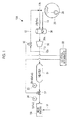
- Fig. 1 is a block diagram schematically illustrating an entire configuration of a fuel supply apparatus according to a first embodiment of the invention.
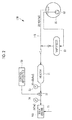
- Fig. 2 is a block diagram schematically illustrating an entire configuration of a fuel supply apparatus according to a second embodiment of the invention. Description of Embodiments
- Fig. 1 is a block diagram schematically illustrating an entire configuration of a fuel supply apparatus 10A supplying a fuel to a steam turbine-type main engine (main engine for propulsion) 100 provided in an LNG vessel.
- the fuel supply apparatus 10A includes a cargo tank 20 storing LNG, an LNG supply line (gas supply line) 11A supplying the boil-off gas of LNG generated in the cargo tank 20 to a boiler (not illustrated) in the main engine 100, and a fuel oil supply line 51 supplying heavy oil or light oil (fuel oil) to the boiler (not illustrated) in the main engine 100 from a fuel tank (not illustrated).
- a compressor 30, a heater 31, and a supply pressure-adjusting valve 32 are provided in the supply line 11A for fuel gas of LNG in a boil-off gas-flowing direction.
- the compressor 30 is one of pressure-increasing means for increasing the pressure and temperature of the boil-off gas in the supply line 11A for fuel gas of LNG and supplying the boil-off gas to the downstream side.
- the heater 31 increases the temperature of the fuel gas of LNG being supplied to the boiler in the main engine 100.
- the supply pressure-adjusting valve 32 adjusts the flow rate and pressure of the fuel gas of LNG being supplied to the boiler in the main engine 100, and pressure meters 33 and 34 are provided on the inlet and outlet sides of the supply pressure-adjusting valve respectively.
- the degree of opening of the supply pressure-adjusting valve 32 is controlled using a control apparatus 50 while monitoring the detection values of the pressure meters 33 and 34.
- a return line (circulation line) 12 that is one of pressure-increasing means is provided in series between a branching section 12a located on the downstream side of the compressor 30 and on the upper stream side of the heater 31 and a convergence section 12b located on the upper stream side of the compressor 30 and on the outlet side of the cargo tank 20.
- a line pressure control valve 35 adjusting the gas pressure on the upper stream side of the supply pressure-adjusting valve 32 in the supply line 11A for fuel gas of LNG is provided in the return line 12, and the opening/closing and degree of opening of the line pressure control valve are controlled using the control apparatus 50.
- a mist separator 36 (cooling means) is provided on the downstream side of the convergence section 12b in the return line 12 and on the upper stream side of the compressor 30.
- the mist separator 36 collects a liquid-phase component of LNG contained in the mixture of the boil-off gas of LNG stored in the cargo tank 20 and the excess gas returned from the downstream side of the compressor 30 when the mixture is cooled by LNG spraying before or in the mist separator.
- a spray nozzle (not illustrated) for cooling the boil-off gas in the supply line 11A for fuel gas of LNG is provided in a container 36a.
- a pump 38 submerged in a liquid phase in the cargo tank 20 feeds the LNG to the spray nozzle through a LNG supply line 13. Therefore, it becomes possible to blow liquid LNG pumped up from the inside of the cargo tank 20 using the pump 38 to the mixture of the boil-off gas and the excess gas returned from the compressor 30 in the container 36a from the spray nozzle through the LNG supply line 13.
- the main engine 100 is capable of selectively using as a fuel the boil-off gas being supplied from the supply line 11A for fuel gas of LNG and heavy oil or light oil being supplied from the fuel oil supply line 51 depending on navigation, the driving state, and the like. That is, the load state of the main engine 100 is detected based on the operation mode selected by the marine vessel operator, a variety of monitoring values monitored using a variety of sensors, and the like, and the control apparatus 50 controls the switching between the supply of the boil-off gas from the supply line 11A for fuel gas of LNG and the supply of heavy oil or light oil from the fuel oil supply line 51 to the main engine 100 depending on the detected load state of the main engine 100 based on the predetermined computer program.
- the boil-off gas is supplied to the main engine 100 as a fuel.
- the boil-off gas generated in the cargo tank 20 is supplied to the supply line 11A for fuel gas of LNG.
- the boil-off gas of LNG is sent to the compressor 30 after the liquid-phase component contained in the gas is removed in the mist separator 36.
- the pressure and temperature of the boil-off gas of LNG are increased in the compressor 30, and the temperature of the boil-off gas of LNG is further increased in the heater 31.
- the boil-off gas is sent to the main engine 100 as a fuel after the flow rate and pressure of the boil-off gas of LNG are adjusted in the supply pressure-adjusting valve 32.
- the marine vessel navigates in a co-combustion state of the boil-off gas of LNG and heavy oil or light oil.
- heavy oil or light oil is supplied to the main engine 100 from the fuel tank (not illustrated) through the fuel oil supply line 51 together with the boil-off gas of LNG being supplied through the supply line 11A for fuel gas of LNG.
- any configuration may be used for the supply of heavy oil or light oil, and the configuration will not be described in detail.
- the pressure of the boil-off gas of LNG is controlled to be increased in the supply line 11A for fuel gas of LNG before the navigation mode using only LNG is switched to a navigation mode through the co-combustion of LNG and heavy oil or light oil.
- the navigation speed, the pressure of the supply gas to the main engine 100 at the pressure meter 34, and the like are monitored in the control apparatus 50, and, when the navigation speed, the pressure and the like are detected to be lower than the previously-specified threshold values, the supply pressure-adjusting valve 32 is squeezed. Then, the pressure of the boil-off gas of LNG in the supply line 11A for fuel gas of LNG is increased. At this time, the pressure of the boil-off gas of LNG in the supply line 11A for fuel gas of LNG is desirably set in a range of, for example, 10 kPaG to 40 kPaG. In this state, the pressure on the downstream side of the supply pressure-adjusting valve 32, that is, the pressure of gas being supplied to the main engine 100 is set to, for example, 5 kPaG.
- gas pressure in the supply line 11A for fuel gas of LNG on the upper stream side of the supply pressure-adjusting valve 32 is increased to a pressure in a range of 10 kPaG to 40 kPaG, the pressure of the boil-off gas of LNG being supplied to the main engine 100 is instantly increased, and it is possible to form a large combustion flame from the burner in the boiler. Then, it is possible to reliably ignite the burner for heavy oil or light oil and to reliably switch fuels.
- the line pressure control valve 35 is opened. Then, excess boil-off gas of LNG is circulated to the upper stream side of the compressor 30 through the return line 12 in a state in which the supply pressure-adjusting valve 32 is squeezed, the boil-off gas of LNG is not uselessly consumed.
- the boil-off gas of LNG being circulated through the return line 12 is pressurized using the compressor 30, whereby the temperature of the boil-off gas of LNG increases. Therefore, when the circulation is repeated, the temperature of boil-off gas of LNG in the supply line 11A for fuel gas of LNG gradually increases. Therefore, it is possible to decrease the temperature of the boil-off gas of LNG by blowing the LNG in the cargo tank 20 to the boil-off gas of LNG from the spray nozzle before or in the mist separator 36, and a stable operation can be carried out.
- a fuel supply apparatus 10B in the embodiment includes the cargo tank 20 storing LNG, a supply line (gas supply line) 11B supplying the boil-off gas of LNG generated in the cargo tank 20 to the boiler (not illustrated) in the main engine 100, and the fuel oil supply line 51.
- the heater 31 and the supply pressure-adjusting valve 32 are provided in the supply line 11B for fuel gas of LNG in a boil-off gas-flowing direction.
- An evaporator (pressure-increasing means) 61 evaporating the LNG pumped up using a pump 62 submerged in the liquid phase in the cargo tank 20 by pressurizing and heating the LNG is connected to the supply line 11B for fuel gas of LNG on the upper stream side of the heater 31.
- the evaporator 61 employs a heating method using steam vapor or hot water.
- Gas of LNG obtained by heating the LNG using the evaporator 61 is converged with the boil-off gas in the supply line 11B for fuel gas of LNG on the upper stream side of the heater 31.
- a vaporizer can be used as the evaporator.
- the main engine 100 is capable of selectively using as a fuel the boil-off gas of LNG being supplied from the supply line 11B for fuel gas of LNG and heavy oil or light oil being supplied from the fuel oil supply line 51 depending on navigation, the driving state, and the like.
- the pressure of the boil-off gas of LNG is controlled to be increased in the supply line 11B for fuel gas of LNG before the navigation mode using only LNG is switched to the navigation mode in which heavy oil or light oil is used.
- the navigation speed, the pressure of the supply gas to the main engine 100 at the pressure meter 34, and the like are monitored in the control apparatus 50, and, when the navigation speed, the pressure and the like are detected to be lower than the previously-specified threshold values, the vaporizer 61 is operated. Then, the gas of LNG obtained through heating using the vaporizer 61 is converged with the boil-off gas of LNG in the supply line 11B for fuel gas of LNG on the upper stream side of the heater 31. Therefore, the pressure of the boil-off gas of LNG is increased.
- the pressure of the boil-off gas of LNG in the supply line 11B for fuel gas of LNG is desirably set in a range of, for example, 20 kPaG to 40 kPaG.
- the pressure on the downstream side of the supply pressure-adjusting valve 32, that is, the pressure of gas being supplied to the main engine 100 is set to, for example, 5 kPaG.
- the invention for example, the fuel supply apparatuses 10A and 10B according to the invention can also be applied to an LPG vessel or the like in addition to the LNG vessel.
- LPG vessel or the like in addition to the LNG vessel.
- any configurations are available except for the configurations of the fuel supply apparatuses 10A and 10B.
- other components may be used as long as the components are capable of realizing the same function.
- the combination of the first embodiment and the second embodiment is also possible. That is, the vaporizer 61 illustrated in Fig. 2 may be jointly provided to the configuration illustrated in Fig. 1 .
Landscapes
- Engineering & Computer Science (AREA)
- Chemical & Material Sciences (AREA)
- Combustion & Propulsion (AREA)
- Mechanical Engineering (AREA)
- General Engineering & Computer Science (AREA)
- Oil, Petroleum & Natural Gas (AREA)
- Ocean & Marine Engineering (AREA)
- Chemical Kinetics & Catalysis (AREA)
- General Chemical & Material Sciences (AREA)
- Filling Or Discharging Of Gas Storage Vessels (AREA)
- Feeding And Controlling Fuel (AREA)
Abstract
Description
- The present invention relates to a marine vessel, a fuel supply apparatus, and a method for supplying fuel gas of liquefied medium to a main engine for marine vessel propulsion.
- In marine vessels, heavy oil has been widely used as a fuel, but there has been a demand for suppressing a sulfur component contained in exhaust gas after the combustion of the fuel from the viewpoint of environmental protection. Therefore, active efforts are being made to switch the fuel from heavy oil to liquefied gas containing no sulfur component.
- Meanwhile, in a liquefied natural gas (LNG) carrier, LNG loaded as a cargo is used as a fuel for a steam turbine main engine for carrier propulsion (hereinafter, simply referred to as main engine).
- However, it is stipulated by Class rule that, if there is any problem with the supply of the fuel when LNG is used as a fuel, the fuel is supposed to be switched to heavy oil or light oil.
- Therefore, there has been a proposal for a configuration in which not only LNG but also heavy oil or light oil are used as the fuel, and LNG and heavy oil or light oil are appropriately switched depending on a variety of conditions (for example, refer to PTL 1).
- [PTL 1] Japanese Unexamined Patent Application Publication No.
2006-177618 - However, in a state in which LNG is supplied as a fuel for the main engine, the supply amount and supply pressure of LNG decrease in a state of a low-load navigation in which the navigation speed is decreased to bring a marine vessel into a port compared with a state in ocean going. In addition, when the load on the main engine for marine vessel propulsion significantly changes due to the acceleration and deceleration of a marine vessel in a port or the like, there is a concern of the main engine trip in a case in which only LNG is used as the fuel. Therefore, in the port, a marine vessel navigates in a switched state in which LNG and heavy oil or light oil are co-combusted as the fuel.
- In a case in which the fuel is switched to heavy oil or light oil from LNG, a burner for LNG and a burner for heavy oil or light oil are separately provided, and the burner for heavy oil or light oil is ignited using the combustion flame of the burner for LNG. At this time, since the supply amount and supply pressure of LNG are low in the low-load navigation state, the combustion flame is small, and there is a possibility of a failure of ignition. Therefore, when the fuel is switched to heavy oil or light oil from LNG, the pressure of LNG is increased in advance to a pressure of, for example, 10 kPaG using a compressor.
- The increase in the pressure of LNG as described above is carried out while monitoring the load state and the like of the main engine in a control apparatus of the main engine.
- Therefore, for example, in a case in which a marine vessel comes into the low-load navigation state by decreasing the navigation speed when coming into a port, in the control apparatus of the main engine, the pressure of LNG is increased by operating the compressor, and the flame of a gas burner is intensified so as to make the switching of the fuel from the single fuel combustion of LNG to the co-combustion with heavy oil or light oil possible at all times.
- However, in the above-described example, LNG used to intensify the flame of the gas burner by increasing the pressure until the fuel is actually switched to the co-combustion with heavy oil or light oil is not effectively used, and the LNG fuel is uselessly consumed. Additionally, vapor generated from the combustion of the fuel is not effectively used, and is uselessly exhausted.
- The invention has been made in consideration of the above-described circumstances, and an object of the invention is to provide a marine vessel, a fuel supply apparatus, and a method for supplying fuel gas of liquefied medium to a main engine for marine vessel propulsion which are capable of reliably switching the fuel from LNG to the co-combustion with heavy oil or light oil by suppressing the useless consumption of the fuel.
- To solve the above-described problems, the vessel of the invention employs the following means.
- That is, according to a first aspect of the invention, there is provided a marine vessel including a main engine for marine vessel propulsion capable of selectively using fuel gas of LNG and fuel oil as a fuel, a gas supply line supplying the fuel gas of LNG to the main engine for propulsion, a fuel oil supply line supplying the fuel oil to the main engine for propulsion, pressure-increasing means for increasing a pressure of the fuel gas of LNG in the gas supply line, a supply pressure-adjusting valve adjusting a supply pressure when supplying the fuel gas of LNG in the gas supply line to the main engine for propulsion, and a control apparatus increasing the pressure of the fuel gas of LNG using the pressure-increasing means depending on a load on the main engine for marine vessel propulsion and opening the supply pressure-adjusting valve so as to supply the fuel gas of LNG pressurized to a predetermined pressure to the main engine for propulsion before a state in which the fuel gas of LNG is supplied to the main engine for marine vessel propulsion from the gas supply line is transferred to a state in which the fuel oil is supplied to the main engine for marine vessel propulsion from the fuel oil supply line.
- According to the first aspect, when the state in which the fuel gas of LNG is supplied to the main engine for marine vessel propulsion from the gas supply line is transferred to the state in which the fuel oil is supplied to the main engine for marine vessel propulsion from the fuel oil supply line, if the supply pressure-adjusting valve is opened, since the fuel gas of LNG on the upper stream side of the supply pressure-adjusting valve is in a pressurized state, it is possible to instantly enlarge the flame of the fuel gas of LNG in the main engine for propulsion. Therefore, reliable ignition can be carried out.
- Furthermore, since the fuel gas of LNG is all in a pressurized state on the upper stream side of the supply pressure-adjusting valve, and the fuel gas of LNG depressurized using the supply pressure-adjusting valve is supplied to the main engine for marine vessel propulsion until the fuel gas of LNG is switched to the fuel oil, it is possible to suppress the useless consumption of the fuel gas of liquefied medium.
- Any configuration may be used as the pressure-increasing means, and, for example, it is possible to further include a compressor being provided on an upper stream side of the supply pressure-adjusting valve and pressurizing the fuel gas of LNG flowing in the gas supply line, and a circulation line circulating the fuel gas of LNG to the upper stream of the compressor from a branching section between the compressor and the supply pressure-adjusting valve.
- When the fuel gas of LNG is circulated on the upper stream side of the supply pressure-adjusting valve as described above, it is possible to put the fuel gas of LNG into a pressurized state without uselessly consuming the fuel gas of liquefied medium.
- At this time, a line pressure-adjusting valve adjusting the pressure of the fuel gas of LNG in the gas supply line is preferably provided in the circulation line.
- Meanwhile, when the fuel gas of LNG is circulated as described above, the fuel gas of LNG passes through the compressor several times, and consequently the temperature of the fuel gas of LNG increases.
- Therefore, cooling means for cooling the fuel gas of LNG flowing in the gas supply line is preferably further provided. Examples of the cooling means include the blowing of LNG to the gas-state fuel gas of liquefied medium. Needless to say, other methods may be used.
- In addition, it is preferable to provide the pressure-increasing means on the upper stream side of the supply pressure-adjusting valve, and to provide an evaporator increasing the pressure of the fuel gas of LNG flowing in the gas supply line.
- As the pressure-increasing means, additionally, it is possible to gasify LNG extracted from a tank containing LNG through evaporation and supply the gasified LNG to the gas supply line. Specifically, it is possible to use a vaporizer. Therefore, the fuel gas of LNG can be pressurized without using the compressor.
- The control apparatus is capable of not carrying out the pressurization of the fuel gas of LNG using the circulation line or the evaporator in the pressure-increasing means when the load on the main engine for marine vessel propulsion is at a first level and carrying out the pressurization of the fuel gas of LNG using the circulation line or the pressure-increasing means including the evaporator before the state in which the fuel gas of LNG is supplied to the main engine for marine vessel propulsion from the gas supply line is transferred to the state in which the fuel oil is supplied to the main engine for marine vessel propulsion from the fuel oil supply line when the load on the main engine for marine vessel propulsion is at a second level that is lower than the first level.
- According to a second aspect of the invention, there is provided a fuel supply apparatus supplying a fuel gas of LNG to the main engine for marine vessel propulsion capable of selectively using the fuel gas of LNG and a fuel oil as a fuel, including a gas supply line supplying the fuel gas of LNG to the main engine for propulsion, pressure-increasing means for increasing a pressure of the fuel gas of LNG in the gas supply line, a supply pressure-adjusting valve adjusting a supply pressure when supplying the fuel gas of LNG in the gas supply line to the main engine for propulsion, and a control apparatus increasing the pressure of the fuel gas of LNG using the pressure-increasing means depending on a load on the main engine for marine vessel propulsion and opening the supply pressure-adjusting valve so as to supply the pressurized fuel gas of LNG to the main engine for propulsion before a state in which the fuel gas of LNG is supplied to the main engine for marine vessel propulsion from the gas supply line is transferred to a state in which the fuel oil is supplied to the main engine for marine vessel propulsion from the fuel oil supply line.
- According to a third aspect of the invention, there is provided a method for navigating the above-described marine vessel, including a step of increasing a pressure of the fuel gas of LNG depending on a load on the main engine for marine vessel propulsion using pressure-increasing means when a state in which the fuel gas of LNG is supplied to the main engine for marine vessel propulsion from the gas supply line is transferred to a state in which the fuel oil is supplied to the main engine for marine vessel propulsion from the fuel oil supply line, and a step of opening the supply pressure-adjusting valve so as to supply the pressurized fuel gas of LNG to the main engine for propulsion and igniting the fuel oil using a flame of the fuel gas of LNG.
- In addition, according to a fourth aspect of the invention, there is provided a method for driving the above-described marine vessel, in which a pressure of the fuel gas of LNG located on the upper stream side of the supply pressure-adjusting valve in the gas supply line is previously increased, and the pressurized fuel gas of LNG is supplied to the main engine for propulsion. Advantageous Effects of Invention
- When the state in which the fuel gas of LNG is supplied to the main engine for marine vessel propulsion from the gas supply line is transferred to the state in which the fuel oil is supplied to the main engine for marine vessel propulsion from the fuel oil supply line, if the supply pressure-adjusting valve is opened, since the fuel gas of LNG on the upper stream side of the supply pressure-adjusting valve is in a pressurized state, it is possible to instantly enlarge the flame of the fuel gas of LNG in the main engine for propulsion. Therefore, reliable ignition can be carried out.
- Furthermore, since the fuel gas of LNG is all in a pressurized state on the upper stream side of the supply pressure-adjusting valve, and the fuel gas of LNG depressurized using the supply pressure-adjusting valve is supplied to the main engine for marine vessel propulsion until the fuel gas of LNG is switched to the fuel oil, it is possible to suppress the useless consumption of the fuel gas of LNG.
- As a result, it is possible to suppress the useless fuel consumption and to reliably switch the fuel from LNG to heavy oil or light oil.
-
Fig. 1 is a block diagram schematically illustrating an entire configuration of a fuel supply apparatus according to a first embodiment of the invention. -
Fig. 2 is a block diagram schematically illustrating an entire configuration of a fuel supply apparatus according to a second embodiment of the invention. Description of Embodiments - Hereinafter, embodiments of the marine vessel, the fuel supply apparatus, and the supply method according to the invention, the method in a case in which, for example, liquefied natural gas (LNG) is used as fuel gas for a main engine for marine vessel propulsion will be described with reference to the accompanying drawings.
- Hereinafter, a first embodiment of the invention will be described using
Fig. 1 . -
Fig. 1 is a block diagram schematically illustrating an entire configuration of afuel supply apparatus 10A supplying a fuel to a steam turbine-type main engine (main engine for propulsion) 100 provided in an LNG vessel. Thefuel supply apparatus 10A includes acargo tank 20 storing LNG, an LNG supply line (gas supply line) 11A supplying the boil-off gas of LNG generated in thecargo tank 20 to a boiler (not illustrated) in themain engine 100, and a fueloil supply line 51 supplying heavy oil or light oil (fuel oil) to the boiler (not illustrated) in themain engine 100 from a fuel tank (not illustrated). - A
compressor 30, aheater 31, and a supply pressure-adjustingvalve 32 are provided in thesupply line 11A for fuel gas of LNG in a boil-off gas-flowing direction. - The
compressor 30 is one of pressure-increasing means for increasing the pressure and temperature of the boil-off gas in thesupply line 11A for fuel gas of LNG and supplying the boil-off gas to the downstream side. - The
heater 31 increases the temperature of the fuel gas of LNG being supplied to the boiler in themain engine 100. - The supply pressure-adjusting
valve 32 adjusts the flow rate and pressure of the fuel gas of LNG being supplied to the boiler in themain engine 100, andpressure meters valve 32 is controlled using acontrol apparatus 50 while monitoring the detection values of thepressure meters - In the
supply line 11A for fuel gas of LNG, a return line (circulation line) 12 that is one of pressure-increasing means is provided in series between abranching section 12a located on the downstream side of thecompressor 30 and on the upper stream side of theheater 31 and aconvergence section 12b located on the upper stream side of thecompressor 30 and on the outlet side of thecargo tank 20. - A line
pressure control valve 35 adjusting the gas pressure on the upper stream side of the supply pressure-adjustingvalve 32 in thesupply line 11A for fuel gas of LNG is provided in thereturn line 12, and the opening/closing and degree of opening of the line pressure control valve are controlled using thecontrol apparatus 50. - In the
return line 12, excess gas determined depending on the gas pressure on the upper stream side of the supply pressure-adjustingvalve 32 that is determined depending on the degree of opening of the supply pressure-adjustingvalve 32 is circulated to theconvergence section 12b on the outlet side of thecargo tank 20 from thebranching section 12a on the downstream side of thecompressor 30. - In the
supply line 11A for fuel gas of LNG, a mist separator 36 (cooling means) is provided on the downstream side of theconvergence section 12b in thereturn line 12 and on the upper stream side of thecompressor 30. Themist separator 36 collects a liquid-phase component of LNG contained in the mixture of the boil-off gas of LNG stored in thecargo tank 20 and the excess gas returned from the downstream side of thecompressor 30 when the mixture is cooled by LNG spraying before or in the mist separator. - Before or in the
mist separator 36, a spray nozzle (not illustrated) for cooling the boil-off gas in thesupply line 11A for fuel gas of LNG is provided in acontainer 36a. Apump 38 submerged in a liquid phase in thecargo tank 20 feeds the LNG to the spray nozzle through aLNG supply line 13. Therefore, it becomes possible to blow liquid LNG pumped up from the inside of thecargo tank 20 using thepump 38 to the mixture of the boil-off gas and the excess gas returned from thecompressor 30 in thecontainer 36a from the spray nozzle through theLNG supply line 13. - The
main engine 100 is capable of selectively using as a fuel the boil-off gas being supplied from thesupply line 11A for fuel gas of LNG and heavy oil or light oil being supplied from the fueloil supply line 51 depending on navigation, the driving state, and the like. That is, the load state of themain engine 100 is detected based on the operation mode selected by the marine vessel operator, a variety of monitoring values monitored using a variety of sensors, and the like, and thecontrol apparatus 50 controls the switching between the supply of the boil-off gas from thesupply line 11A for fuel gas of LNG and the supply of heavy oil or light oil from the fueloil supply line 51 to themain engine 100 depending on the detected load state of themain engine 100 based on the predetermined computer program. - In a case ocean going, the boil-off gas is supplied to the
main engine 100 as a fuel. In this case, in thefuel supply apparatus 10A, the boil-off gas generated in thecargo tank 20 is supplied to thesupply line 11A for fuel gas of LNG. The boil-off gas of LNG is sent to thecompressor 30 after the liquid-phase component contained in the gas is removed in themist separator 36. - The pressure and temperature of the boil-off gas of LNG are increased in the
compressor 30, and the temperature of the boil-off gas of LNG is further increased in theheater 31. - In addition, the boil-off gas is sent to the
main engine 100 as a fuel after the flow rate and pressure of the boil-off gas of LNG are adjusted in the supply pressure-adjustingvalve 32. - Meanwhile, in this mode, the line
pressure control valve 35 is closed, and the boil-off gas of LNG is not circulated through thereturn line 12. - In a case in which a marine vessel navigates in a port at a low speed, the marine vessel navigates in a co-combustion state of the boil-off gas of LNG and heavy oil or light oil. Specifically, heavy oil or light oil is supplied to the
main engine 100 from the fuel tank (not illustrated) through the fueloil supply line 51 together with the boil-off gas of LNG being supplied through thesupply line 11A for fuel gas of LNG. Meanwhile, any configuration may be used for the supply of heavy oil or light oil, and the configuration will not be described in detail. - In a state in which a marine vessel comes into a port from outside and is in an navigation mode using only LNG, when the load on the
main engine 100 turns from a normal navigation state (first level) into a low-load navigation state (second level) in which the navigation speed is decreased so that the load on themain engine 100 is lower than the load in the normal navigation state, the pressure of the boil-off gas of LNG is controlled to be increased in thesupply line 11A for fuel gas of LNG before the navigation mode using only LNG is switched to a navigation mode through the co-combustion of LNG and heavy oil or light oil. - For the control of increasing the pressure of the boil-off gas of LNG, the navigation speed, the pressure of the supply gas to the
main engine 100 at thepressure meter 34, and the like are monitored in thecontrol apparatus 50, and, when the navigation speed, the pressure and the like are detected to be lower than the previously-specified threshold values, the supply pressure-adjustingvalve 32 is squeezed. Then, the pressure of the boil-off gas of LNG in thesupply line 11A for fuel gas of LNG is increased. At this time, the pressure of the boil-off gas of LNG in thesupply line 11A for fuel gas of LNG is desirably set in a range of, for example, 10 kPaG to 40 kPaG. In this state, the pressure on the downstream side of the supply pressure-adjustingvalve 32, that is, the pressure of gas being supplied to themain engine 100 is set to, for example, 5 kPaG. - In addition, when a navigation mode in which the boil-off gas of LNG is supplied to the
main engine 100 from thesupply line 11A for fuel gas of LNG is transferred to a navigation mode in which heavy oil or light oil is supplied to themain engine 100 from the fueloil supply line 51 together with the boil-off gas of LNG, in thecontrol apparatus 50, as soon as a signal indicating the fact that the switching operation of the navigation mode has been completed is received, the supply pressure-adjustingvalve 32 is opened. Then, since gas pressure in thesupply line 11A for fuel gas of LNG on the upper stream side of the supply pressure-adjustingvalve 32 is increased to a pressure in a range of 10 kPaG to 40 kPaG, the pressure of the boil-off gas of LNG being supplied to themain engine 100 is instantly increased, and it is possible to form a large combustion flame from the burner in the boiler. Then, it is possible to reliably ignite the burner for heavy oil or light oil and to reliably switch fuels. - At this time, together with the above-described squeezing operation of the supply pressure-adjusting
valve 32, the linepressure control valve 35 is opened. Then, excess boil-off gas of LNG is circulated to the upper stream side of thecompressor 30 through thereturn line 12 in a state in which the supply pressure-adjustingvalve 32 is squeezed, the boil-off gas of LNG is not uselessly consumed. - As described above, the boil-off gas of LNG being circulated through the
return line 12 is pressurized using thecompressor 30, whereby the temperature of the boil-off gas of LNG increases. Therefore, when the circulation is repeated, the temperature of boil-off gas of LNG in thesupply line 11A for fuel gas of LNG gradually increases. Therefore, it is possible to decrease the temperature of the boil-off gas of LNG by blowing the LNG in thecargo tank 20 to the boil-off gas of LNG from the spray nozzle before or in themist separator 36, and a stable operation can be carried out. - According to the above-described configuration, it is possible to suppress the useless consumption of the fuel and to reliably switch the fuel from LNG to heavy oil or light oil.
- In addition, since only the minimum extent of modification such as the additional provision of the
return line 12, the linepressure control valve 35 and the like, and the change in the control program for thecontrol apparatus 50 is required for the existing marine vessels, it is possible to obtain the above-described effects at a low cost. - Next, a second embodiment of the invention will be described. In the following description, the same components as the component described in the first embodiment are given the same reference sign, and will not be described again.
- As illustrated in
Fig. 2 , afuel supply apparatus 10B in the embodiment includes thecargo tank 20 storing LNG, a supply line (gas supply line) 11B supplying the boil-off gas of LNG generated in thecargo tank 20 to the boiler (not illustrated) in themain engine 100, and the fueloil supply line 51. - The
heater 31 and the supply pressure-adjustingvalve 32 are provided in thesupply line 11B for fuel gas of LNG in a boil-off gas-flowing direction. - An evaporator (pressure-increasing means) 61 evaporating the LNG pumped up using a
pump 62 submerged in the liquid phase in thecargo tank 20 by pressurizing and heating the LNG is connected to thesupply line 11B for fuel gas of LNG on the upper stream side of theheater 31. Theevaporator 61 employs a heating method using steam vapor or hot water. - Gas of LNG obtained by heating the LNG using the
evaporator 61 is converged with the boil-off gas in thesupply line 11B for fuel gas of LNG on the upper stream side of theheater 31. Furthermore, for example, a vaporizer can be used as the evaporator. - Similar to the first embodiment, the
main engine 100 is capable of selectively using as a fuel the boil-off gas of LNG being supplied from thesupply line 11B for fuel gas of LNG and heavy oil or light oil being supplied from the fueloil supply line 51 depending on navigation, the driving state, and the like. - In the above-described configuration, when the normal navigation state is turned into the low-load navigation state by decreasing the navigation speed in a state of the navigation mode using only LNG, the pressure of the boil-off gas of LNG is controlled to be increased in the
supply line 11B for fuel gas of LNG before the navigation mode using only LNG is switched to the navigation mode in which heavy oil or light oil is used. - For the control of increasing the pressure of the boil-off gas of LNG, the navigation speed, the pressure of the supply gas to the
main engine 100 at thepressure meter 34, and the like are monitored in thecontrol apparatus 50, and, when the navigation speed, the pressure and the like are detected to be lower than the previously-specified threshold values, thevaporizer 61 is operated. Then, the gas of LNG obtained through heating using thevaporizer 61 is converged with the boil-off gas of LNG in thesupply line 11B for fuel gas of LNG on the upper stream side of theheater 31. Therefore, the pressure of the boil-off gas of LNG is increased. At this time, the pressure of the boil-off gas of LNG in thesupply line 11B for fuel gas of LNG is desirably set in a range of, for example, 20 kPaG to 40 kPaG. In this state, the pressure on the downstream side of the supply pressure-adjustingvalve 32, that is, the pressure of gas being supplied to themain engine 100 is set to, for example, 5 kPaG. - As described above, if the pressure of the boil-off gas of LNG has been increased, and the supply pressure-adjusting
valve 32 is opened using thecontrol apparatus 50 when the fuel is switched from LNG to heavy oil or light oil, it is possible to instantly form a large combustion flame for ignition, and to carry out reliable ignition and the reliable switching of fuels. - According to the above-described configuration, it is possible to suppress the useless consumption of the fuel and to reliably switch the fuel from LNG to heavy oil or light oil.
- In addition, in the existing marine vessels as well, the same configuration components as described above are provided in terms of hardware. Therefore, only the minimum extent of modification is required by changing the control program for the
control apparatus 50, it is possible to obtain the above-described effects at a low cost. - Meanwhile, in the above-described respective embodiments, the invention, for example, the
fuel supply apparatuses fuel supply apparatuses fuel supply apparatuses - Furthermore, the combination of the first embodiment and the second embodiment is also possible. That is, the
vaporizer 61 illustrated inFig. 2 may be jointly provided to the configuration illustrated inFig. 1 . - In addition to what has been described above, any other configurations may be employed within the scope of the main concept of the invention.
-
- 10A, 10B
- FUEL SUPPLY APPARATUS
- 11A, 11B
- SUPPLY LINE FOR FUEL GAS OR LNG
- 12
- RETURN LINE (CIRCULATION LINE)
- 12a
- BRANCHING SECTION
- 12b
- CONVERGENCE SECTION
- 13
- LNG SUPPLY LINE
- 20
- CARGO TANK
- 30
- COMPRESSOR
- 31
- HEATER
- 32
- SUPPLY PRESSURE-ADJUSTING VALVE
- 35
- LINE PRESSURE CONTROL VALVE
- 36
- MIST SEPARATOR
- 36a
- CONTAINER
- 38
- PUMP
- 50
- CONTROL APPARATUS
- 51
- FUEL OIL SUPPLY LINE
- 61
- VAPORIZER (PRESSURE-INCREASING COOLING MEANS)
- 100
- MAIN ENGINE (MAIN ENGINE FOR PROPULSION)
Claims (10)
- A marine vessel comprising:a main engine for marine vessel propulsion capable of selectively using fuel gas of LNG and fuel oil as a fuel;a fuel gas supply line supplying the fuel gas of LNG to the main engine for propulsion;a fuel oil supply line supplying the fuel oil to the main engine for propulsion;pressure-increasing means for increasing a pressure of the fuel gas of LNG in the fuel gas supply line;a supply pressure-adjusting valve adjusting a supply pressure when supplying the fuel gas of LNG in the fuel gas supply line to the main engine for propulsion; anda control apparatus increasing the pressure of the fuel gas of LNG using the pressure-increasing means depending on a load on the main engine for marine vessel propulsion and opening the supply pressure-adjusting valve so as to supply the fuel gas of LNG pressurized to a predetermined pressure to the main engine for propulsion before a state in which the fuel gas of LNG is supplied to the main engine for marine vessel propulsion from the fuel gas supply line is transferred to a state in which the fuel oil is supplied to the main engine for marine vessel propulsion from the fuel oil supply line.
- The marine vessel according to Claim 1,
wherein the pressure-increasing means includes
a compressor being provided on an upper stream side of the supply pressure-adjusting valve and pressurizing the fuel gas of LNG flowing in the fuel gas supply line, and
a circulation line circulating the fuel gas of LNG to the upper stream side of the compressor from a branching section between the compressor and the supply pressure-adjusting valve. - The marine vessel according to Claim 2,
wherein a line pressure-adjusting valve adjusting the pressure of the fuel gas of LNG in the fuel gas supply line is provided in the circulation line. - The marine vessel according to Claim 2 or 3, further comprising:cooling means being provided on a upper stream side of the compressor and cooling the fuel gas of LNG flowing in the fuel gas supply line.
- The marine vessel according to Claim 1 or 2,
wherein the pressure-increasing means includes an evaporator being provided on an upper stream side of the supply pressure-adjusting valve and increasing the pressure of the fuel gas of LNG flowing in the fuel gas supply line. - The marine vessel according to any one of Claims 1 to 5,
wherein the pressure-increasing means extracts the LNG from a tank containing the LNG, gasifies the LNG through evaporation, and supplies the gasified LNG to the fuel gas supply line. - The marine vessel according to any one of Claims 1 to 6,
wherein the control apparatus is capable of not carrying out the pressurization of the fuel gas of LNG using the circulation line or the evaporator in the pressure-increasing means when the load on the main engine for marine vessel propulsion is at a first level, and
carrying out the pressurization of the fuel gas of LNG using the circulation line or the pressure-increasing means including the evaporator before the state in which the fuel gas of LNG is supplied to the main engine for marine vessel propulsion from the fuel gas supply line is transferred to the state in which the fuel oil is supplied to the main engine for marine vessel propulsion from the fuel oil supply line when the load on the main engine for marine vessel propulsion is at a second level that is lower than the first level. - A fuel supply apparatus supplying a fuel gas of LNG to the main engine for marine vessel propulsion capable of selectively using the fuel gas of LNG and a fuel oil as a fuel, comprising:a fuel gas supply line supplying the fuel gas of LNG to the main engine for propulsion;pressure-increasing means for increasing a pressure of the fuel gas of LNG in the fuel gas supply line;a supply pressure-adjusting valve adjusting a supply pressure when supplying the fuel gas of LNG in the fuel gas supply line to the main engine for propulsion; anda control apparatus increasing the pressure of the fuel gas of LNG using the pressure-increasing means depending on a load on the main engine for marine vessel propulsion and opening the supply pressure-adjusting valve so as to supply the pressurized fuel gas of LNG to the main engine for propulsion before a state in which the fuel gas of LNG is supplied to the main engine for marine vessel propulsion from the fuel gas supply line is transferred to a state in which the fuel oil is supplied to the main engine for marine vessel propulsion from the fuel oil supply line.
- A method for navigating the marine vessel according to any one of Claims 1 to 7, comprising:a step of increasing a pressure of the fuel gas of LNG using pressure-increasing means depending on a load on the main engine for marine vessel propulsion before a state in which the fuel gas of LNG is supplied to the main engine for marine vessel propulsion from the fuel gas supply line is transferred to a state in which the fuel oil is supplied to the main engine for marine vessel propulsion from the fuel oil supply line; anda step of opening the supply pressure-adjusting valve so as to supply the pressurized fuel gas of LNG to the main engine for propulsion and igniting the fuel oil using a flame of the fuel gas of LNG.
- A method for driving the marine vessel according to any one of Claims 1 to 7,
wherein a pressure of the fuel gas of LNG located on the upper stream side of the supply pressure-adjusting valve in the fuel gas supply line is previously increased, and
the pressurized fuel gas of LNG is supplied to the main engine for propulsion.
Applications Claiming Priority (2)
| Application Number | Priority Date | Filing Date | Title |
|---|---|---|---|
| JP2012081012A JP5627628B2 (en) | 2012-03-30 | 2012-03-30 | Method of supplying liquefied fuel gas to ship, fuel supply device, main engine for propulsion |
| PCT/JP2013/057265 WO2013146314A1 (en) | 2012-03-30 | 2013-03-14 | Marine vessel, fuel-supplying device, and method for supplying liquefied fuel gas to main engine for propulsion |
Publications (3)
| Publication Number | Publication Date |
|---|---|
| EP2833063A1 true EP2833063A1 (en) | 2015-02-04 |
| EP2833063A4 EP2833063A4 (en) | 2015-11-18 |
| EP2833063B1 EP2833063B1 (en) | 2017-05-10 |
Family
ID=49259577
Family Applications (1)
| Application Number | Title | Priority Date | Filing Date |
|---|---|---|---|
| EP13768573.1A Not-in-force EP2833063B1 (en) | 2012-03-30 | 2013-03-14 | Marine vessel, fuel-supplying device, and method for supplying liquefied fuel gas to main engine for propulsion |
Country Status (5)
| Country | Link |
|---|---|
| EP (1) | EP2833063B1 (en) |
| JP (1) | JP5627628B2 (en) |
| KR (1) | KR101521065B1 (en) |
| CN (1) | CN104094060B (en) |
| WO (1) | WO2013146314A1 (en) |
Families Citing this family (23)
| Publication number | Priority date | Publication date | Assignee | Title |
|---|---|---|---|---|
| JP6457760B2 (en) * | 2014-08-08 | 2019-01-23 | 川崎重工業株式会社 | Ship |
| JP6401544B2 (en) * | 2014-08-08 | 2018-10-10 | 川崎重工業株式会社 | Gas supply system and ship equipped with the same |
| JP2016049881A (en) * | 2014-08-29 | 2016-04-11 | 川崎重工業株式会社 | Ship |
| JP6491474B2 (en) * | 2014-12-26 | 2019-03-27 | 川崎重工業株式会社 | Liquefied gas carrier |
| JP2016124388A (en) * | 2014-12-26 | 2016-07-11 | 川崎重工業株式会社 | Liquefied gas carrying vessel |
| RU2686651C2 (en) * | 2015-01-30 | 2019-04-29 | Дэу Шипбилдинг Энд Марин Инджиниринг Ко., Лтд. | System and method for controlling fuel supply to ship motor |
| JP6500576B2 (en) * | 2015-04-24 | 2019-04-17 | 株式会社三井E&Sマシナリー | Fuel supply device and ship |
| JP6741691B2 (en) | 2015-06-02 | 2020-08-19 | デウ シップビルディング アンド マリン エンジニアリング カンパニー リミテッド | Ship |
| JP6899335B2 (en) | 2015-06-02 | 2021-07-07 | デウ シップビルディング アンド マリン エンジニアリング カンパニー リミテッド | Ship |
| PL3305645T3 (en) * | 2015-06-02 | 2024-06-10 | Hanwha Ocean Co., Ltd. | Boil-off gas treatment system for a ship |
| JP6521444B2 (en) * | 2015-07-17 | 2019-05-29 | 三井E&S造船株式会社 | Fuel gas supply system for ships |
| JP6670088B2 (en) * | 2015-12-18 | 2020-03-18 | 川崎重工業株式会社 | Ship |
| JP6613179B2 (en) * | 2016-03-16 | 2019-11-27 | 川崎重工業株式会社 | Liquefied gas carrier |
| JP6239027B2 (en) * | 2016-04-25 | 2017-11-29 | 三井造船株式会社 | Fuel gas supply system for liquefied gas carrier |
| JP7078204B2 (en) * | 2017-05-10 | 2022-05-31 | 三井E&S造船株式会社 | Liquefied gas fuel ship |
| US11473730B2 (en) * | 2017-07-31 | 2022-10-18 | Daewoo Shipbuilding & Marine Engineering Co., Ltd. | Boil-off gas reliquefication system, method for discharging lubricating oil in boil-off gas reliquefication system, and engine fuel supply method |
| WO2019088308A1 (en) * | 2017-10-30 | 2019-05-09 | 대우조선해양 주식회사 | Fuel oil supply system and method for ship |
| JP7319769B2 (en) * | 2018-10-03 | 2023-08-02 | 三菱重工マリンマシナリ株式会社 | Exhaust heat recovery system, ship, and exhaust heat recovery device operating method |
| KR102141086B1 (en) * | 2019-11-14 | 2020-08-05 | 주식회사 동화엔텍 | Space-intensive LNG Fuel Supply System for Small Scale Vessel |
| CN113090417B (en) * | 2021-03-29 | 2022-07-22 | 招商局重工(深圳)有限公司 | LPG gas-liquid separation jar and fuel control system |
| CN114215649B (en) * | 2021-12-31 | 2023-11-17 | 潍柴动力股份有限公司 | Method and device for controlling conversion of light and heavy oil of engine in linkage mode |
| JP7793813B2 (en) * | 2022-04-14 | 2026-01-05 | ヒュンダイ ヘビー インダストリーズ パワー システムズ カンパニー リミテッド | Fuel supply system |
| CN119510006B (en) * | 2024-11-14 | 2025-10-17 | 中国舰船研究设计中心 | Ship land joint debugging test fuel oil supply and recovery system and method |
Family Cites Families (16)
| Publication number | Priority date | Publication date | Assignee | Title |
|---|---|---|---|---|
| US2767691A (en) * | 1955-02-07 | 1956-10-23 | Phillips Petroleum Co | Dual-fuel engines and processes of operating same |
| JPS5957094A (en) * | 1982-09-27 | 1984-04-02 | Hitachi Zosen Corp | Utilizing method of boil-off gas in lng carrying ship |
| JPS62139937A (en) * | 1985-12-11 | 1987-06-23 | Mitsubishi Heavy Ind Ltd | Fuel control device for engine |
| JP2554053B2 (en) * | 1986-04-16 | 1996-11-13 | 三菱重工業株式会社 | Engine fuel controller |
| JP3082510B2 (en) * | 1993-05-28 | 2000-08-28 | 石川島播磨重工業株式会社 | Main engine control device in liquefied gas carrier |
| JPH0781670A (en) * | 1993-09-16 | 1995-03-28 | Mitsubishi Heavy Ind Ltd | Methanol synthesizing device support type electric propulsion system lng ship |
| DE20101475U1 (en) * | 2001-01-28 | 2002-06-13 | Winkelmann, Karlheinrich, Dipl.-Ing. (TH), 33617 Bielefeld | direct injection |
| JP3806356B2 (en) * | 2002-02-05 | 2006-08-09 | 三菱重工業株式会社 | Liquefied natural gas processing equipment and liquefied natural gas carrier |
| DE10245161A1 (en) * | 2002-09-26 | 2004-04-08 | Winkelmann, Karlheinrich, Dipl.-Ing. (TH) | Fuel injection system for combustion engine regulates additional fuel (e.g. LPG) fed to combustion chamber with lambda probe in exhaust flow upstream of catalyser and associated control electronics |
| DE102004011414A1 (en) * | 2003-10-05 | 2005-04-28 | Karlheinrich Winkelmann | Internal combustion engine has fuel mixture during engine running created continuously in dosing and mixing valve and mixing ratio of fuels can be simultaneously influenced through control unit |
| FR2879261B1 (en) * | 2004-12-10 | 2007-04-13 | Alstom Sa | INSTALLATION FOR THE DELIVERY OF GASEOUS FUEL TO AN ENERGY PRODUCTION ASSEMBLY OF A LIQUEFIED GAS TRANSPORT VESSEL |
| JP4275061B2 (en) * | 2004-12-22 | 2009-06-10 | 三菱重工業株式会社 | Fuel supply apparatus and LNG ship equipped with the same |
| JP2009203944A (en) * | 2008-02-28 | 2009-09-10 | Mitsubishi Heavy Ind Ltd | Method and device for supplying gas fuel of binary fuel engine |
| JP5167158B2 (en) * | 2009-01-29 | 2013-03-21 | 三菱重工業株式会社 | Liquefied fuel carrier and its propulsion system |
| JP2010223424A (en) * | 2009-02-27 | 2010-10-07 | Mitsubishi Heavy Ind Ltd | Vaporized gas supply device |
| US8783041B2 (en) * | 2010-06-09 | 2014-07-22 | Chevron U.S.A. Inc. | LNG transport vessel and method for storing and managing excess boil off gas thereon |
-
2012
- 2012-03-30 JP JP2012081012A patent/JP5627628B2/en active Active
-
2013
- 2013-03-14 KR KR1020147019982A patent/KR101521065B1/en not_active Expired - Fee Related
- 2013-03-14 CN CN201380007461.5A patent/CN104094060B/en not_active Expired - Fee Related
- 2013-03-14 WO PCT/JP2013/057265 patent/WO2013146314A1/en not_active Ceased
- 2013-03-14 EP EP13768573.1A patent/EP2833063B1/en not_active Not-in-force
Also Published As
| Publication number | Publication date |
|---|---|
| JP2013210148A (en) | 2013-10-10 |
| CN104094060A (en) | 2014-10-08 |
| EP2833063B1 (en) | 2017-05-10 |
| JP5627628B2 (en) | 2014-11-19 |
| KR20140107504A (en) | 2014-09-04 |
| EP2833063A4 (en) | 2015-11-18 |
| WO2013146314A1 (en) | 2013-10-03 |
| CN104094060B (en) | 2015-12-30 |
| KR101521065B1 (en) | 2015-05-15 |
Similar Documents
| Publication | Publication Date | Title |
|---|---|---|
| EP2833063B1 (en) | Marine vessel, fuel-supplying device, and method for supplying liquefied fuel gas to main engine for propulsion | |
| EP2659120B1 (en) | A fuel feeding system and method of operating a fuel feeding system | |
| JP6630144B2 (en) | Ship | |
| US9863370B2 (en) | Method of starting gas delivery from a liquefied gas fuel system to a gas operated engine and a liquefied gas fuel system for a gas operated engine | |
| EP2832972B1 (en) | Ship, fuel gas supply apparatus, and fuel gas supply method | |
| EP2939918B1 (en) | Natural gas fuel evaporator, natural gas fuel supply device, and method for supplying natural gas fuel to ships and motors | |
| CN104956140B (en) | Method for filling fuel tank with liquefied gas and liquefied gas fuel system | |
| JP6678077B2 (en) | Ship | |
| EP3252296B1 (en) | Fuel supply system and method for ship engine | |
| JP6379304B2 (en) | Fuel gas supply system | |
| KR20180090368A (en) | Ship | |
| KR102075241B1 (en) | Regasification System of liquefied Gas and Ship Having the Same | |
| KR101713857B1 (en) | Lng fueled ship | |
| KR101370065B1 (en) | Fuel gas supply system and method | |
| KR20150092771A (en) | A Treatment System Of Liquefied Gas | |
| JP6757217B2 (en) | Ship | |
| JP2018505987A (en) | Fuel supply control system and fuel supply control method for marine engine | |
| KR101761981B1 (en) | A Treatment System Of Liquefied Gas | |
| KR101259951B1 (en) | Waste heat supply system and ship with the system | |
| KR20160086440A (en) | Fuel gas supplying system in ships | |
| KR20190036087A (en) | Fuel supply system | |
| Price | Marine and Offshore Applications |
Legal Events
| Date | Code | Title | Description |
|---|---|---|---|
| PUAI | Public reference made under article 153(3) epc to a published international application that has entered the european phase |
Free format text: ORIGINAL CODE: 0009012 |
|
| 17P | Request for examination filed |
Effective date: 20140711 |
|
| AK | Designated contracting states |
Kind code of ref document: A1 Designated state(s): AL AT BE BG CH CY CZ DE DK EE ES FI FR GB GR HR HU IE IS IT LI LT LU LV MC MK MT NL NO PL PT RO RS SE SI SK SM TR |
|
| AX | Request for extension of the european patent |
Extension state: BA ME |
|
| DAX | Request for extension of the european patent (deleted) | ||
| RA4 | Supplementary search report drawn up and despatched (corrected) |
Effective date: 20151021 |
|
| RIC1 | Information provided on ipc code assigned before grant |
Ipc: B63H 21/38 20060101ALI20151015BHEP Ipc: F23K 5/02 20060101ALI20151015BHEP Ipc: F23K 5/00 20060101AFI20151015BHEP |
|
| GRAP | Despatch of communication of intention to grant a patent |
Free format text: ORIGINAL CODE: EPIDOSNIGR1 |
|
| INTG | Intention to grant announced |
Effective date: 20161213 |
|
| GRAS | Grant fee paid |
Free format text: ORIGINAL CODE: EPIDOSNIGR3 |
|
| GRAA | (expected) grant |
Free format text: ORIGINAL CODE: 0009210 |
|
| AK | Designated contracting states |
Kind code of ref document: B1 Designated state(s): AL AT BE BG CH CY CZ DE DK EE ES FI FR GB GR HR HU IE IS IT LI LT LU LV MC MK MT NL NO PL PT RO RS SE SI SK SM TR |
|
| REG | Reference to a national code |
Ref country code: GB Ref legal event code: FG4D |
|
| REG | Reference to a national code |
Ref country code: AT Ref legal event code: REF Ref document number: 892759 Country of ref document: AT Kind code of ref document: T Effective date: 20170515 Ref country code: CH Ref legal event code: EP |
|
| REG | Reference to a national code |
Ref country code: IE Ref legal event code: FG4D |
|
| REG | Reference to a national code |
Ref country code: DE Ref legal event code: R096 Ref document number: 602013020999 Country of ref document: DE |
|
| REG | Reference to a national code |
Ref country code: NL Ref legal event code: MP Effective date: 20170510 |
|
| REG | Reference to a national code |
Ref country code: LT Ref legal event code: MG4D |
|
| REG | Reference to a national code |
Ref country code: NO Ref legal event code: T2 Effective date: 20170510 |
|
| REG | Reference to a national code |
Ref country code: AT Ref legal event code: MK05 Ref document number: 892759 Country of ref document: AT Kind code of ref document: T Effective date: 20170510 |
|
| PG25 | Lapsed in a contracting state [announced via postgrant information from national office to epo] |
Ref country code: AT Free format text: LAPSE BECAUSE OF FAILURE TO SUBMIT A TRANSLATION OF THE DESCRIPTION OR TO PAY THE FEE WITHIN THE PRESCRIBED TIME-LIMIT Effective date: 20170510 Ref country code: FI Free format text: LAPSE BECAUSE OF FAILURE TO SUBMIT A TRANSLATION OF THE DESCRIPTION OR TO PAY THE FEE WITHIN THE PRESCRIBED TIME-LIMIT Effective date: 20170510 Ref country code: HR Free format text: LAPSE BECAUSE OF FAILURE TO SUBMIT A TRANSLATION OF THE DESCRIPTION OR TO PAY THE FEE WITHIN THE PRESCRIBED TIME-LIMIT Effective date: 20170510 Ref country code: LT Free format text: LAPSE BECAUSE OF FAILURE TO SUBMIT A TRANSLATION OF THE DESCRIPTION OR TO PAY THE FEE WITHIN THE PRESCRIBED TIME-LIMIT Effective date: 20170510 Ref country code: GR Free format text: LAPSE BECAUSE OF FAILURE TO SUBMIT A TRANSLATION OF THE DESCRIPTION OR TO PAY THE FEE WITHIN THE PRESCRIBED TIME-LIMIT Effective date: 20170811 Ref country code: ES Free format text: LAPSE BECAUSE OF FAILURE TO SUBMIT A TRANSLATION OF THE DESCRIPTION OR TO PAY THE FEE WITHIN THE PRESCRIBED TIME-LIMIT Effective date: 20170510 |
|
| PG25 | Lapsed in a contracting state [announced via postgrant information from national office to epo] |
Ref country code: BG Free format text: LAPSE BECAUSE OF FAILURE TO SUBMIT A TRANSLATION OF THE DESCRIPTION OR TO PAY THE FEE WITHIN THE PRESCRIBED TIME-LIMIT Effective date: 20170810 Ref country code: RS Free format text: LAPSE BECAUSE OF FAILURE TO SUBMIT A TRANSLATION OF THE DESCRIPTION OR TO PAY THE FEE WITHIN THE PRESCRIBED TIME-LIMIT Effective date: 20170510 Ref country code: LV Free format text: LAPSE BECAUSE OF FAILURE TO SUBMIT A TRANSLATION OF THE DESCRIPTION OR TO PAY THE FEE WITHIN THE PRESCRIBED TIME-LIMIT Effective date: 20170510 Ref country code: PL Free format text: LAPSE BECAUSE OF FAILURE TO SUBMIT A TRANSLATION OF THE DESCRIPTION OR TO PAY THE FEE WITHIN THE PRESCRIBED TIME-LIMIT Effective date: 20170510 Ref country code: SE Free format text: LAPSE BECAUSE OF FAILURE TO SUBMIT A TRANSLATION OF THE DESCRIPTION OR TO PAY THE FEE WITHIN THE PRESCRIBED TIME-LIMIT Effective date: 20170510 Ref country code: NL Free format text: LAPSE BECAUSE OF FAILURE TO SUBMIT A TRANSLATION OF THE DESCRIPTION OR TO PAY THE FEE WITHIN THE PRESCRIBED TIME-LIMIT Effective date: 20170510 Ref country code: IS Free format text: LAPSE BECAUSE OF FAILURE TO SUBMIT A TRANSLATION OF THE DESCRIPTION OR TO PAY THE FEE WITHIN THE PRESCRIBED TIME-LIMIT Effective date: 20170910 |
|
| PG25 | Lapsed in a contracting state [announced via postgrant information from national office to epo] |
Ref country code: EE Free format text: LAPSE BECAUSE OF FAILURE TO SUBMIT A TRANSLATION OF THE DESCRIPTION OR TO PAY THE FEE WITHIN THE PRESCRIBED TIME-LIMIT Effective date: 20170510 Ref country code: CZ Free format text: LAPSE BECAUSE OF FAILURE TO SUBMIT A TRANSLATION OF THE DESCRIPTION OR TO PAY THE FEE WITHIN THE PRESCRIBED TIME-LIMIT Effective date: 20170510 Ref country code: DK Free format text: LAPSE BECAUSE OF FAILURE TO SUBMIT A TRANSLATION OF THE DESCRIPTION OR TO PAY THE FEE WITHIN THE PRESCRIBED TIME-LIMIT Effective date: 20170510 Ref country code: RO Free format text: LAPSE BECAUSE OF FAILURE TO SUBMIT A TRANSLATION OF THE DESCRIPTION OR TO PAY THE FEE WITHIN THE PRESCRIBED TIME-LIMIT Effective date: 20170510 Ref country code: SK Free format text: LAPSE BECAUSE OF FAILURE TO SUBMIT A TRANSLATION OF THE DESCRIPTION OR TO PAY THE FEE WITHIN THE PRESCRIBED TIME-LIMIT Effective date: 20170510 |
|
| REG | Reference to a national code |
Ref country code: DE Ref legal event code: R097 Ref document number: 602013020999 Country of ref document: DE |
|
| PG25 | Lapsed in a contracting state [announced via postgrant information from national office to epo] |
Ref country code: SM Free format text: LAPSE BECAUSE OF FAILURE TO SUBMIT A TRANSLATION OF THE DESCRIPTION OR TO PAY THE FEE WITHIN THE PRESCRIBED TIME-LIMIT Effective date: 20170510 Ref country code: IT Free format text: LAPSE BECAUSE OF FAILURE TO SUBMIT A TRANSLATION OF THE DESCRIPTION OR TO PAY THE FEE WITHIN THE PRESCRIBED TIME-LIMIT Effective date: 20170510 |
|
| PLBE | No opposition filed within time limit |
Free format text: ORIGINAL CODE: 0009261 |
|
| STAA | Information on the status of an ep patent application or granted ep patent |
Free format text: STATUS: NO OPPOSITION FILED WITHIN TIME LIMIT |
|
| 26N | No opposition filed |
Effective date: 20180213 |
|
| PG25 | Lapsed in a contracting state [announced via postgrant information from national office to epo] |
Ref country code: SI Free format text: LAPSE BECAUSE OF FAILURE TO SUBMIT A TRANSLATION OF THE DESCRIPTION OR TO PAY THE FEE WITHIN THE PRESCRIBED TIME-LIMIT Effective date: 20170510 |
|
| REG | Reference to a national code |
Ref country code: NO Ref legal event code: CHAD Owner name: MITSUBISHI SHIPBUILDING CO., JP |
|
| REG | Reference to a national code |
Ref country code: DE Ref legal event code: R119 Ref document number: 602013020999 Country of ref document: DE |
|
| REG | Reference to a national code |
Ref country code: CH Ref legal event code: PL |
|
| GBPC | Gb: european patent ceased through non-payment of renewal fee |
Effective date: 20180314 |
|
| PG25 | Lapsed in a contracting state [announced via postgrant information from national office to epo] |
Ref country code: MC Free format text: LAPSE BECAUSE OF FAILURE TO SUBMIT A TRANSLATION OF THE DESCRIPTION OR TO PAY THE FEE WITHIN THE PRESCRIBED TIME-LIMIT Effective date: 20170510 |
|
| REG | Reference to a national code |
Ref country code: BE Ref legal event code: MM Effective date: 20180331 |
|
| REG | Reference to a national code |
Ref country code: IE Ref legal event code: MM4A |
|
| PG25 | Lapsed in a contracting state [announced via postgrant information from national office to epo] |
Ref country code: LU Free format text: LAPSE BECAUSE OF NON-PAYMENT OF DUE FEES Effective date: 20180314 |
|
| PG25 | Lapsed in a contracting state [announced via postgrant information from national office to epo] |
Ref country code: IE Free format text: LAPSE BECAUSE OF NON-PAYMENT OF DUE FEES Effective date: 20180314 Ref country code: DE Free format text: LAPSE BECAUSE OF NON-PAYMENT OF DUE FEES Effective date: 20181002 |
|
| PG25 | Lapsed in a contracting state [announced via postgrant information from national office to epo] |
Ref country code: LI Free format text: LAPSE BECAUSE OF NON-PAYMENT OF DUE FEES Effective date: 20180331 Ref country code: GB Free format text: LAPSE BECAUSE OF NON-PAYMENT OF DUE FEES Effective date: 20180314 Ref country code: BE Free format text: LAPSE BECAUSE OF NON-PAYMENT OF DUE FEES Effective date: 20180331 Ref country code: CH Free format text: LAPSE BECAUSE OF NON-PAYMENT OF DUE FEES Effective date: 20180331 |
|
| PG25 | Lapsed in a contracting state [announced via postgrant information from national office to epo] |
Ref country code: FR Free format text: LAPSE BECAUSE OF NON-PAYMENT OF DUE FEES Effective date: 20180331 |
|
| PG25 | Lapsed in a contracting state [announced via postgrant information from national office to epo] |
Ref country code: MT Free format text: LAPSE BECAUSE OF NON-PAYMENT OF DUE FEES Effective date: 20180314 |
|
| PG25 | Lapsed in a contracting state [announced via postgrant information from national office to epo] |
Ref country code: TR Free format text: LAPSE BECAUSE OF FAILURE TO SUBMIT A TRANSLATION OF THE DESCRIPTION OR TO PAY THE FEE WITHIN THE PRESCRIBED TIME-LIMIT Effective date: 20170510 |
|
| PG25 | Lapsed in a contracting state [announced via postgrant information from national office to epo] |
Ref country code: PT Free format text: LAPSE BECAUSE OF FAILURE TO SUBMIT A TRANSLATION OF THE DESCRIPTION OR TO PAY THE FEE WITHIN THE PRESCRIBED TIME-LIMIT Effective date: 20170510 |
|
| PG25 | Lapsed in a contracting state [announced via postgrant information from national office to epo] |
Ref country code: CY Free format text: LAPSE BECAUSE OF FAILURE TO SUBMIT A TRANSLATION OF THE DESCRIPTION OR TO PAY THE FEE WITHIN THE PRESCRIBED TIME-LIMIT Effective date: 20170510 Ref country code: HU Free format text: LAPSE BECAUSE OF FAILURE TO SUBMIT A TRANSLATION OF THE DESCRIPTION OR TO PAY THE FEE WITHIN THE PRESCRIBED TIME-LIMIT; INVALID AB INITIO Effective date: 20130314 Ref country code: MK Free format text: LAPSE BECAUSE OF NON-PAYMENT OF DUE FEES Effective date: 20170510 |
|
| PG25 | Lapsed in a contracting state [announced via postgrant information from national office to epo] |
Ref country code: AL Free format text: LAPSE BECAUSE OF FAILURE TO SUBMIT A TRANSLATION OF THE DESCRIPTION OR TO PAY THE FEE WITHIN THE PRESCRIBED TIME-LIMIT Effective date: 20170510 |
|
| PGFP | Annual fee paid to national office [announced via postgrant information from national office to epo] |
Ref country code: NO Payment date: 20240222 Year of fee payment: 12 |
|
| PG25 | Lapsed in a contracting state [announced via postgrant information from national office to epo] |
Ref country code: NO Free format text: LAPSE BECAUSE OF NON-PAYMENT OF DUE FEES Effective date: 20250331 |