EP3252296B1 - Fuel supply system and method for ship engine - Google Patents
Fuel supply system and method for ship engine Download PDFInfo
- Publication number
- EP3252296B1 EP3252296B1 EP15880207.4A EP15880207A EP3252296B1 EP 3252296 B1 EP3252296 B1 EP 3252296B1 EP 15880207 A EP15880207 A EP 15880207A EP 3252296 B1 EP3252296 B1 EP 3252296B1
- Authority
- EP
- European Patent Office
- Prior art keywords
- lng
- pressure
- pressure pump
- engine
- storage tank
- Prior art date
- Legal status (The legal status is an assumption and is not a legal conclusion. Google has not performed a legal analysis and makes no representation as to the accuracy of the status listed.)
- Active
Links
- 239000000446 fuel Substances 0.000 title claims description 42
- 238000000034 method Methods 0.000 title claims description 7
- 238000011144 upstream manufacturing Methods 0.000 claims description 9
- 238000002347 injection Methods 0.000 claims description 8
- 239000007924 injection Substances 0.000 claims description 8
- 230000001105 regulatory effect Effects 0.000 claims description 7
- 239000006200 vaporizer Substances 0.000 claims description 5
- 239000003949 liquefied natural gas Substances 0.000 description 110
- 239000007789 gas Substances 0.000 description 21
- VNWKTOKETHGBQD-UHFFFAOYSA-N methane Chemical compound C VNWKTOKETHGBQD-UHFFFAOYSA-N 0.000 description 12
- MWUXSHHQAYIFBG-UHFFFAOYSA-N Nitric oxide Chemical compound O=[N] MWUXSHHQAYIFBG-UHFFFAOYSA-N 0.000 description 6
- 238000010586 diagram Methods 0.000 description 6
- 239000003345 natural gas Substances 0.000 description 5
- CURLTUGMZLYLDI-UHFFFAOYSA-N Carbon dioxide Chemical compound O=C=O CURLTUGMZLYLDI-UHFFFAOYSA-N 0.000 description 2
- 239000000809 air pollutant Substances 0.000 description 2
- 231100001243 air pollutant Toxicity 0.000 description 2
- 230000001276 controlling effect Effects 0.000 description 2
- TXKMVPPZCYKFAC-UHFFFAOYSA-N disulfur monoxide Inorganic materials O=S=S TXKMVPPZCYKFAC-UHFFFAOYSA-N 0.000 description 2
- 239000003915 liquefied petroleum gas Substances 0.000 description 2
- 239000007788 liquid Substances 0.000 description 2
- 230000004048 modification Effects 0.000 description 2
- 238000012986 modification Methods 0.000 description 2
- 238000010248 power generation Methods 0.000 description 2
- XTQHKBHJIVJGKJ-UHFFFAOYSA-N sulfur monoxide Chemical compound S=O XTQHKBHJIVJGKJ-UHFFFAOYSA-N 0.000 description 2
- 230000033228 biological regulation Effects 0.000 description 1
- 229910002092 carbon dioxide Inorganic materials 0.000 description 1
- 239000001569 carbon dioxide Substances 0.000 description 1
- 239000000969 carrier Substances 0.000 description 1
- 238000002485 combustion reaction Methods 0.000 description 1
- 238000001816 cooling Methods 0.000 description 1
- 230000009977 dual effect Effects 0.000 description 1
- 230000000694 effects Effects 0.000 description 1
- 239000003344 environmental pollutant Substances 0.000 description 1
- 230000008020 evaporation Effects 0.000 description 1
- 238000001704 evaporation Methods 0.000 description 1
- 239000002737 fuel gas Substances 0.000 description 1
- 239000000295 fuel oil Substances 0.000 description 1
- 238000002309 gasification Methods 0.000 description 1
- 238000010438 heat treatment Methods 0.000 description 1
- 229910017464 nitrogen compound Inorganic materials 0.000 description 1
- 150000002830 nitrogen compounds Chemical class 0.000 description 1
- 239000003921 oil Substances 0.000 description 1
- 231100000719 pollutant Toxicity 0.000 description 1
- 239000000243 solution Substances 0.000 description 1
- 230000006641 stabilisation Effects 0.000 description 1
- 238000011105 stabilization Methods 0.000 description 1
- 150000003464 sulfur compounds Chemical class 0.000 description 1
- 230000008016 vaporization Effects 0.000 description 1
Images
Classifications
-
- B—PERFORMING OPERATIONS; TRANSPORTING
- B63—SHIPS OR OTHER WATERBORNE VESSELS; RELATED EQUIPMENT
- B63B—SHIPS OR OTHER WATERBORNE VESSELS; EQUIPMENT FOR SHIPPING
- B63B25/00—Load-accommodating arrangements, e.g. stowing, trimming; Vessels characterised thereby
- B63B25/02—Load-accommodating arrangements, e.g. stowing, trimming; Vessels characterised thereby for bulk goods
- B63B25/08—Load-accommodating arrangements, e.g. stowing, trimming; Vessels characterised thereby for bulk goods fluid
- B63B25/12—Load-accommodating arrangements, e.g. stowing, trimming; Vessels characterised thereby for bulk goods fluid closed
- B63B25/14—Load-accommodating arrangements, e.g. stowing, trimming; Vessels characterised thereby for bulk goods fluid closed pressurised
-
- B—PERFORMING OPERATIONS; TRANSPORTING
- B63—SHIPS OR OTHER WATERBORNE VESSELS; RELATED EQUIPMENT
- B63H—MARINE PROPULSION OR STEERING
- B63H21/00—Use of propulsion power plant or units on vessels
- B63H21/12—Use of propulsion power plant or units on vessels the vessels being motor-driven
- B63H21/14—Use of propulsion power plant or units on vessels the vessels being motor-driven relating to internal-combustion engines
-
- B—PERFORMING OPERATIONS; TRANSPORTING
- B63—SHIPS OR OTHER WATERBORNE VESSELS; RELATED EQUIPMENT
- B63H—MARINE PROPULSION OR STEERING
- B63H21/00—Use of propulsion power plant or units on vessels
- B63H21/38—Apparatus or methods specially adapted for use on marine vessels, for handling power plant or unit liquids, e.g. lubricants, coolants, fuels or the like
-
- F—MECHANICAL ENGINEERING; LIGHTING; HEATING; WEAPONS; BLASTING
- F02—COMBUSTION ENGINES; HOT-GAS OR COMBUSTION-PRODUCT ENGINE PLANTS
- F02B—INTERNAL-COMBUSTION PISTON ENGINES; COMBUSTION ENGINES IN GENERAL
- F02B73/00—Combinations of two or more engines, not otherwise provided for
-
- F—MECHANICAL ENGINEERING; LIGHTING; HEATING; WEAPONS; BLASTING
- F02—COMBUSTION ENGINES; HOT-GAS OR COMBUSTION-PRODUCT ENGINE PLANTS
- F02M—SUPPLYING COMBUSTION ENGINES IN GENERAL WITH COMBUSTIBLE MIXTURES OR CONSTITUENTS THEREOF
- F02M21/00—Apparatus for supplying engines with non-liquid fuels, e.g. gaseous fuels stored in liquid form
- F02M21/02—Apparatus for supplying engines with non-liquid fuels, e.g. gaseous fuels stored in liquid form for gaseous fuels
- F02M21/0218—Details on the gaseous fuel supply system, e.g. tanks, valves, pipes, pumps, rails, injectors or mixers
- F02M21/023—Valves; Pressure or flow regulators in the fuel supply or return system
- F02M21/0239—Pressure or flow regulators therefor
-
- F—MECHANICAL ENGINEERING; LIGHTING; HEATING; WEAPONS; BLASTING
- F02—COMBUSTION ENGINES; HOT-GAS OR COMBUSTION-PRODUCT ENGINE PLANTS
- F02M—SUPPLYING COMBUSTION ENGINES IN GENERAL WITH COMBUSTIBLE MIXTURES OR CONSTITUENTS THEREOF
- F02M21/00—Apparatus for supplying engines with non-liquid fuels, e.g. gaseous fuels stored in liquid form
- F02M21/02—Apparatus for supplying engines with non-liquid fuels, e.g. gaseous fuels stored in liquid form for gaseous fuels
- F02M21/0218—Details on the gaseous fuel supply system, e.g. tanks, valves, pipes, pumps, rails, injectors or mixers
- F02M21/0287—Details on the gaseous fuel supply system, e.g. tanks, valves, pipes, pumps, rails, injectors or mixers characterised by the transition from liquid to gaseous phase ; Injection in liquid phase; Cooling and low temperature storage
-
- F—MECHANICAL ENGINEERING; LIGHTING; HEATING; WEAPONS; BLASTING
- F02—COMBUSTION ENGINES; HOT-GAS OR COMBUSTION-PRODUCT ENGINE PLANTS
- F02M—SUPPLYING COMBUSTION ENGINES IN GENERAL WITH COMBUSTIBLE MIXTURES OR CONSTITUENTS THEREOF
- F02M37/00—Apparatus or systems for feeding liquid fuel from storage containers to carburettors or fuel-injection apparatus; Arrangements for purifying liquid fuel specially adapted for, or arranged on, internal-combustion engines
- F02M37/04—Feeding by means of driven pumps
-
- F—MECHANICAL ENGINEERING; LIGHTING; HEATING; WEAPONS; BLASTING
- F17—STORING OR DISTRIBUTING GASES OR LIQUIDS
- F17C—VESSELS FOR CONTAINING OR STORING COMPRESSED, LIQUEFIED OR SOLIDIFIED GASES; FIXED-CAPACITY GAS-HOLDERS; FILLING VESSELS WITH, OR DISCHARGING FROM VESSELS, COMPRESSED, LIQUEFIED, OR SOLIDIFIED GASES
- F17C13/00—Details of vessels or of the filling or discharging of vessels
- F17C13/02—Special adaptations of indicating, measuring, or monitoring equipment
- F17C13/025—Special adaptations of indicating, measuring, or monitoring equipment having the pressure as the parameter
-
- F—MECHANICAL ENGINEERING; LIGHTING; HEATING; WEAPONS; BLASTING
- F17—STORING OR DISTRIBUTING GASES OR LIQUIDS
- F17C—VESSELS FOR CONTAINING OR STORING COMPRESSED, LIQUEFIED OR SOLIDIFIED GASES; FIXED-CAPACITY GAS-HOLDERS; FILLING VESSELS WITH, OR DISCHARGING FROM VESSELS, COMPRESSED, LIQUEFIED, OR SOLIDIFIED GASES
- F17C13/00—Details of vessels or of the filling or discharging of vessels
- F17C13/02—Special adaptations of indicating, measuring, or monitoring equipment
- F17C13/026—Special adaptations of indicating, measuring, or monitoring equipment having the temperature as the parameter
-
- F—MECHANICAL ENGINEERING; LIGHTING; HEATING; WEAPONS; BLASTING
- F17—STORING OR DISTRIBUTING GASES OR LIQUIDS
- F17C—VESSELS FOR CONTAINING OR STORING COMPRESSED, LIQUEFIED OR SOLIDIFIED GASES; FIXED-CAPACITY GAS-HOLDERS; FILLING VESSELS WITH, OR DISCHARGING FROM VESSELS, COMPRESSED, LIQUEFIED, OR SOLIDIFIED GASES
- F17C3/00—Vessels not under pressure
- F17C3/02—Vessels not under pressure with provision for thermal insulation
- F17C3/022—Land-based bulk storage containers
-
- F—MECHANICAL ENGINEERING; LIGHTING; HEATING; WEAPONS; BLASTING
- F17—STORING OR DISTRIBUTING GASES OR LIQUIDS
- F17C—VESSELS FOR CONTAINING OR STORING COMPRESSED, LIQUEFIED OR SOLIDIFIED GASES; FIXED-CAPACITY GAS-HOLDERS; FILLING VESSELS WITH, OR DISCHARGING FROM VESSELS, COMPRESSED, LIQUEFIED, OR SOLIDIFIED GASES
- F17C3/00—Vessels not under pressure
- F17C3/02—Vessels not under pressure with provision for thermal insulation
- F17C3/025—Bulk storage in barges or on ships
-
- F—MECHANICAL ENGINEERING; LIGHTING; HEATING; WEAPONS; BLASTING
- F17—STORING OR DISTRIBUTING GASES OR LIQUIDS
- F17C—VESSELS FOR CONTAINING OR STORING COMPRESSED, LIQUEFIED OR SOLIDIFIED GASES; FIXED-CAPACITY GAS-HOLDERS; FILLING VESSELS WITH, OR DISCHARGING FROM VESSELS, COMPRESSED, LIQUEFIED, OR SOLIDIFIED GASES
- F17C9/00—Methods or apparatus for discharging liquefied or solidified gases from vessels not under pressure
- F17C9/02—Methods or apparatus for discharging liquefied or solidified gases from vessels not under pressure with change of state, e.g. vaporisation
-
- F—MECHANICAL ENGINEERING; LIGHTING; HEATING; WEAPONS; BLASTING
- F02—COMBUSTION ENGINES; HOT-GAS OR COMBUSTION-PRODUCT ENGINE PLANTS
- F02M—SUPPLYING COMBUSTION ENGINES IN GENERAL WITH COMBUSTIBLE MIXTURES OR CONSTITUENTS THEREOF
- F02M21/00—Apparatus for supplying engines with non-liquid fuels, e.g. gaseous fuels stored in liquid form
- F02M21/02—Apparatus for supplying engines with non-liquid fuels, e.g. gaseous fuels stored in liquid form for gaseous fuels
- F02M21/0203—Apparatus for supplying engines with non-liquid fuels, e.g. gaseous fuels stored in liquid form for gaseous fuels characterised by the type of gaseous fuel
- F02M21/0215—Mixtures of gaseous fuels; Natural gas; Biogas; Mine gas; Landfill gas
-
- F—MECHANICAL ENGINEERING; LIGHTING; HEATING; WEAPONS; BLASTING
- F02—COMBUSTION ENGINES; HOT-GAS OR COMBUSTION-PRODUCT ENGINE PLANTS
- F02M—SUPPLYING COMBUSTION ENGINES IN GENERAL WITH COMBUSTIBLE MIXTURES OR CONSTITUENTS THEREOF
- F02M21/00—Apparatus for supplying engines with non-liquid fuels, e.g. gaseous fuels stored in liquid form
- F02M21/02—Apparatus for supplying engines with non-liquid fuels, e.g. gaseous fuels stored in liquid form for gaseous fuels
- F02M21/0218—Details on the gaseous fuel supply system, e.g. tanks, valves, pipes, pumps, rails, injectors or mixers
- F02M21/0221—Fuel storage reservoirs, e.g. cryogenic tanks
-
- F—MECHANICAL ENGINEERING; LIGHTING; HEATING; WEAPONS; BLASTING
- F02—COMBUSTION ENGINES; HOT-GAS OR COMBUSTION-PRODUCT ENGINE PLANTS
- F02M—SUPPLYING COMBUSTION ENGINES IN GENERAL WITH COMBUSTIBLE MIXTURES OR CONSTITUENTS THEREOF
- F02M21/00—Apparatus for supplying engines with non-liquid fuels, e.g. gaseous fuels stored in liquid form
- F02M21/02—Apparatus for supplying engines with non-liquid fuels, e.g. gaseous fuels stored in liquid form for gaseous fuels
- F02M21/0218—Details on the gaseous fuel supply system, e.g. tanks, valves, pipes, pumps, rails, injectors or mixers
- F02M21/0245—High pressure fuel supply systems; Rails; Pumps; Arrangement of valves
-
- F—MECHANICAL ENGINEERING; LIGHTING; HEATING; WEAPONS; BLASTING
- F02—COMBUSTION ENGINES; HOT-GAS OR COMBUSTION-PRODUCT ENGINE PLANTS
- F02M—SUPPLYING COMBUSTION ENGINES IN GENERAL WITH COMBUSTIBLE MIXTURES OR CONSTITUENTS THEREOF
- F02M21/00—Apparatus for supplying engines with non-liquid fuels, e.g. gaseous fuels stored in liquid form
- F02M21/02—Apparatus for supplying engines with non-liquid fuels, e.g. gaseous fuels stored in liquid form for gaseous fuels
- F02M21/06—Apparatus for de-liquefying, e.g. by heating
-
- F—MECHANICAL ENGINEERING; LIGHTING; HEATING; WEAPONS; BLASTING
- F17—STORING OR DISTRIBUTING GASES OR LIQUIDS
- F17C—VESSELS FOR CONTAINING OR STORING COMPRESSED, LIQUEFIED OR SOLIDIFIED GASES; FIXED-CAPACITY GAS-HOLDERS; FILLING VESSELS WITH, OR DISCHARGING FROM VESSELS, COMPRESSED, LIQUEFIED, OR SOLIDIFIED GASES
- F17C2250/00—Accessories; Control means; Indicating, measuring or monitoring of parameters
- F17C2250/04—Indicating or measuring of parameters as input values
- F17C2250/0404—Parameters indicated or measured
- F17C2250/0439—Temperature
-
- F—MECHANICAL ENGINEERING; LIGHTING; HEATING; WEAPONS; BLASTING
- F17—STORING OR DISTRIBUTING GASES OR LIQUIDS
- F17C—VESSELS FOR CONTAINING OR STORING COMPRESSED, LIQUEFIED OR SOLIDIFIED GASES; FIXED-CAPACITY GAS-HOLDERS; FILLING VESSELS WITH, OR DISCHARGING FROM VESSELS, COMPRESSED, LIQUEFIED, OR SOLIDIFIED GASES
- F17C2250/00—Accessories; Control means; Indicating, measuring or monitoring of parameters
- F17C2250/06—Controlling or regulating of parameters as output values
- F17C2250/0605—Parameters
- F17C2250/061—Level of content in the vessel
-
- F—MECHANICAL ENGINEERING; LIGHTING; HEATING; WEAPONS; BLASTING
- F17—STORING OR DISTRIBUTING GASES OR LIQUIDS
- F17C—VESSELS FOR CONTAINING OR STORING COMPRESSED, LIQUEFIED OR SOLIDIFIED GASES; FIXED-CAPACITY GAS-HOLDERS; FILLING VESSELS WITH, OR DISCHARGING FROM VESSELS, COMPRESSED, LIQUEFIED, OR SOLIDIFIED GASES
- F17C2250/00—Accessories; Control means; Indicating, measuring or monitoring of parameters
- F17C2250/06—Controlling or regulating of parameters as output values
- F17C2250/0605—Parameters
- F17C2250/0636—Flow or movement of content
-
- F—MECHANICAL ENGINEERING; LIGHTING; HEATING; WEAPONS; BLASTING
- F17—STORING OR DISTRIBUTING GASES OR LIQUIDS
- F17C—VESSELS FOR CONTAINING OR STORING COMPRESSED, LIQUEFIED OR SOLIDIFIED GASES; FIXED-CAPACITY GAS-HOLDERS; FILLING VESSELS WITH, OR DISCHARGING FROM VESSELS, COMPRESSED, LIQUEFIED, OR SOLIDIFIED GASES
- F17C2260/00—Purposes of gas storage and gas handling
- F17C2260/02—Improving properties related to fluid or fluid transfer
- F17C2260/021—Avoiding over pressurising
-
- F—MECHANICAL ENGINEERING; LIGHTING; HEATING; WEAPONS; BLASTING
- F17—STORING OR DISTRIBUTING GASES OR LIQUIDS
- F17C—VESSELS FOR CONTAINING OR STORING COMPRESSED, LIQUEFIED OR SOLIDIFIED GASES; FIXED-CAPACITY GAS-HOLDERS; FILLING VESSELS WITH, OR DISCHARGING FROM VESSELS, COMPRESSED, LIQUEFIED, OR SOLIDIFIED GASES
- F17C2265/00—Effects achieved by gas storage or gas handling
- F17C2265/06—Fluid distribution
- F17C2265/066—Fluid distribution for feeding engines for propulsion
-
- F—MECHANICAL ENGINEERING; LIGHTING; HEATING; WEAPONS; BLASTING
- F25—REFRIGERATION OR COOLING; COMBINED HEATING AND REFRIGERATION SYSTEMS; HEAT PUMP SYSTEMS; MANUFACTURE OR STORAGE OF ICE; LIQUEFACTION SOLIDIFICATION OF GASES
- F25B—REFRIGERATION MACHINES, PLANTS OR SYSTEMS; COMBINED HEATING AND REFRIGERATION SYSTEMS; HEAT PUMP SYSTEMS
- F25B2600/00—Control issues
- F25B2600/05—Refrigerant levels
-
- F—MECHANICAL ENGINEERING; LIGHTING; HEATING; WEAPONS; BLASTING
- F25—REFRIGERATION OR COOLING; COMBINED HEATING AND REFRIGERATION SYSTEMS; HEAT PUMP SYSTEMS; MANUFACTURE OR STORAGE OF ICE; LIQUEFACTION SOLIDIFICATION OF GASES
- F25B—REFRIGERATION MACHINES, PLANTS OR SYSTEMS; COMBINED HEATING AND REFRIGERATION SYSTEMS; HEAT PUMP SYSTEMS
- F25B2600/00—Control issues
- F25B2600/13—Pump speed control
-
- F—MECHANICAL ENGINEERING; LIGHTING; HEATING; WEAPONS; BLASTING
- F25—REFRIGERATION OR COOLING; COMBINED HEATING AND REFRIGERATION SYSTEMS; HEAT PUMP SYSTEMS; MANUFACTURE OR STORAGE OF ICE; LIQUEFACTION SOLIDIFICATION OF GASES
- F25B—REFRIGERATION MACHINES, PLANTS OR SYSTEMS; COMBINED HEATING AND REFRIGERATION SYSTEMS; HEAT PUMP SYSTEMS
- F25B2600/00—Control issues
- F25B2600/25—Control of valves
-
- Y—GENERAL TAGGING OF NEW TECHNOLOGICAL DEVELOPMENTS; GENERAL TAGGING OF CROSS-SECTIONAL TECHNOLOGIES SPANNING OVER SEVERAL SECTIONS OF THE IPC; TECHNICAL SUBJECTS COVERED BY FORMER USPC CROSS-REFERENCE ART COLLECTIONS [XRACs] AND DIGESTS
- Y02—TECHNOLOGIES OR APPLICATIONS FOR MITIGATION OR ADAPTATION AGAINST CLIMATE CHANGE
- Y02T—CLIMATE CHANGE MITIGATION TECHNOLOGIES RELATED TO TRANSPORTATION
- Y02T10/00—Road transport of goods or passengers
- Y02T10/10—Internal combustion engine [ICE] based vehicles
- Y02T10/30—Use of alternative fuels, e.g. biofuels
-
- Y—GENERAL TAGGING OF NEW TECHNOLOGICAL DEVELOPMENTS; GENERAL TAGGING OF CROSS-SECTIONAL TECHNOLOGIES SPANNING OVER SEVERAL SECTIONS OF THE IPC; TECHNICAL SUBJECTS COVERED BY FORMER USPC CROSS-REFERENCE ART COLLECTIONS [XRACs] AND DIGESTS
- Y02—TECHNOLOGIES OR APPLICATIONS FOR MITIGATION OR ADAPTATION AGAINST CLIMATE CHANGE
- Y02T—CLIMATE CHANGE MITIGATION TECHNOLOGIES RELATED TO TRANSPORTATION
- Y02T70/00—Maritime or waterways transport
- Y02T70/50—Measures to reduce greenhouse gas emissions related to the propulsion system
- Y02T70/5218—Less carbon-intensive fuels, e.g. natural gas, biofuels
Definitions
- the present invention relates to a fuel supply system and method for a ship engine, and, more particularly, to a fuel supply system and method for a ship engine in which LNG is delivered from an LNG storage tank of a ship to a high-pressure pump by a submerged pump and then pressurized to a high pressure by high-pressure pump, followed by re-gasifying the LNG pressurized by the high-pressure pump and supplying the re-gasified LNG to the ship engine, wherein LNG upstream of the high-pressure pump is returned to the LNG storage tank to secure a minimum flow rate of the submerged pump, and a flow rate of LNG to be returned is regulated to control a temperature of LNG in front of the high-pressure pump, thereby preventing boil-off gas from flowing into the high-pressure pump.
- LNG liquefied natural gas
- LPG liquefied petroleum gas
- LNG liquefied natural gas
- LNG is a colorless transparent liquid which can be obtained by cooling natural gas containing methane as a main component to about -162°C and has a volume of about 1/600 that of natural gas.
- LNG carriers are used to transport (carry) LNG by sea.
- DFDE dual fuel diesel electric engine
- KR 2012 0092323 discloses a fuel supply system comprising a high-pressure pump receiving LNG from a LNG storage tank.
- US 2014/261327 discloses a fuel supply system for supplying a liquid fuel.
- a fuel supply system for a ship engine is according to claim 1.
- the fuel supply system further includes: a fuel supply channel for supplying LNG from the LNG storage tank to the engine; and a vaporizer disposed in the fuel supply channel, re-gasifying pressurized LNG from the high-pressure pump, and supplying re-gasified LNG to the engine.
- the engine is a high-pressure gas injection engine fueled by a high-pressure gas compressed to a high pressure of 150 bar to 400 bar.
- the LNG storage tank is a pressure-resistant tank and has a design pressure set to retain BOG or flash gas generated in the pressure-resistant tank during operation of the ship.
- a fuel supply method for a ship engine is according to claim 5.
- the engine is a high-pressure gas injection engine fueled by a high-pressure gas compressed to a high pressure of 150 bar to 400 bar.
- the present invention provides a fuel supply system for a ship engine in which LNG is delivered from an LNG storage tank of a ship to a high-pressure pump by a submerged pump and then pressurized to a high pressure by high-pressure pump, followed by re-gasifying the LNG pressurized by the high-pressure pump and supplying the re-gasified LNG to the ship engine, wherein LNG upstream of the high-pressure pump is returned to the LNG storage tank to secure a minimum flow rate of the submerged pump, and a flow rate of LNG to be returned is regulated to control a temperature of LNG in front of the high-pressure pump. Since LNG in front of the high-pressure pump can remain supercooled through control of the flow rate of LNG returned to the LNG storage tank, it is possible to prevent boil-off gas from flowing into the high-pressure pump, thereby preventing system failure and enabling smooth fuel supply.
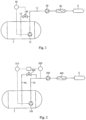
- Fig. 1 is a diagram of an exemplary system for supplying LNG to a ship engine.
- LNG stored in a storage tank T is pumped to a high-pressure pump 20 provided in a supply channel L1 by a delivery pump 10.
- the LNG pressurized by the high-pressure pump 20 is re-gasified by a vaporizer 30 and supplied to a ship engine E as fuel.
- the system is provided with a return channel L2 for returning LNG to the storage tank T.
- the amount of LNG returned to the tank through the return channel L2 may be regulated by controlling a valve 40 disposed in the return channel L2 through a flow controller 50 based on the amount of current consumed by the delivery pump 10.
- Fig. 2 is a schematic diagram of a fuel supply system for a ship engine according to one embodiment of the present invention, which is an improvement of the aforementioned fuel supply system.
- a fuel supply system includes a submerged pump 100 disposed in an LNG storage tank T of a ship and supplying LNG to an engine E of the ship, a high-pressure pump 200 receiving LNG from the submerged pump 100 and pressurizing the LNG to a high pressure, and a return channel RL for returning LNG upstream of the high-pressure pump 200 to the LNG storage tank T to secure a minimum flow rate of the submerged pump 100, wherein a temperature of LNG in front of the high-pressure pump 200 is controlled by regulating a flow rate of LNG returned through the return channel RL.
- the temperature of LNG in front of the high-pressure pump 200 is controlled by regulating the flow rate of LNG returned to the LNG storage tank T.
- the return channel RL branches off upstream of the high-pressure pump 200 as close as possible to the high-pressure pump 200, whereby a flow rate of LNG before the high-pressure pump 200 can be as high as possible, and temperature rise due to heat input from the outside can be reduced, thereby preventing generation of boil-off gas.
- the return channel RL is provided with a flow control valve 300 to control the flow rate of LNG returned to the storage tank.
- the flow control valve 300 controls the flow rate of the LNG returned to the LNG storage tank T under control of a flow controller 310 and a temperature controller 320.
- the flow controller 310 controls the flow rate of LNG returned to the LNG storage tank T to secure a minimum flow rate of the submerged pump 100.
- the flow controller 310 may determine the flow rate of LNG required for securing the minimum flow rate of the submerged pump based on the amount of current consumed by the submerged pump 100.
- the temperature controller 320 detects the temperature of LNG in front of the high-pressure pump 200 and determines the flow rate of LNG returned to the LNG storage tank T required to lower the temperature LNG in front of the high-pressure pump 200 below a liquefaction temperature of LNG, that is, to allow LNG in front of the high-pressure pump 200 to remain supercooled.
- the flow control valve 300 determines the higher of two output values obtained based on control signals from the flow controller 310 and the temperature controller 320 as a flow rate of LNG to be returned to the LNG storage tank T, thereby allowing LNG to be returned to the LNG storage tank T at the determined flow rate. That is, even when the flow rate of the submerged pump 100 signaled by the flow controller 310 is higher than the minimum flow rate, if the temperature of LNG in front of the high-pressure pump 200 is higher than a setting point, a flow rate of LNG returned to the storage tank T is increased based on the signal of the temperature controller 320, thereby allowing LNG in front of the high-pressure pump 200 to remain supercooled.
- the flow rate of LNG to be returned is increased, thereby allowing the temperature of LNG in front of the high-pressure pump 200 to be kept low.
- the fuel supply system may further include a control unit (not shown) receiving control signals from the flow controller 310 and the temperature controller 320 and controlling the flow control valve 300 based on the control signals.
- a control unit (not shown) receiving control signals from the flow controller 310 and the temperature controller 320 and controlling the flow control valve 300 based on the control signals.
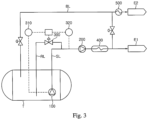
- a vaporizer 400 receiving and re-gasifying LNG pressurized by the high-pressure pump 200 and supplying the re-gasified LNG to the engine E is disposed in a fuel supply channel SL for supplying LNG from the LNG storage tank T to the engine E.
- the engine E is a high-pressure gas injection engine that is fueled by a high-pressure gas compressed to a high pressure of 150 bar to 400 bar, and may be an engine for propulsion or power generation of the ship, for example, an ME-GI engine.
- An ME-GI engine is a 2-stroke high-pressure natural gas injection engine that was developed to reduce emissions of nitrogen oxide (NO x ) and sulfur oxide (SO x ) and can use gases and oils as fuel, and is fueled by a gas compressed to 150 bar to 400 bar.
- NO x nitrogen oxide
- SO x sulfur oxide
- Such an ME-GI engine can reduce pollutant emissions by 23% for carbon dioxide, 80% for nitrogen compounds, and 95% for sulfur compounds, as compared with a diesel engine of equivalent power output.
- the LNG storage tank T is a pressure-resistant tank.
- a pressure-resistant tank may have a design pressure set to hold BOG or flash gas generated therein during operation of the ship.
- the design pressure of the pressure-resistant tank is set to a gauge pressure of 2 bar or higher, preferably 3 bar to 30 bar.
- the pressure-resistant tank may be an independent storage tank, preferably an IMO C-type tank.
- the fuel supply system may further include a second engine E2 that is fueled by BOG generated in the LNG storage tank T.
- Fig. 3 is a diagram of a modification of the above embodiment, which further includes the second engine.
- the second engine E2 is a low-pressure gas engine that is driven at a lower pressure than the ship engine as described above, that is, the first engine E1.
- BOG can be supplied at a pressure required to operate the second engine using only the internal pressure of the LNG storage tank T without using a separate compressor.
- the second engine E2 may be, for example, a DF engine supplied with fuel gas at 3 bar to 20 bar.
- the fuel supply system may further include a BOG supply line BL for supplying BOG from the LNG storage tank T to the second engine and a heater 500 heating BOG.
- LNG is delivered from an LNG storage tank of a ship to a high-pressure pump by a submerged pump and then pressurized to a high pressure by high-pressure pump, followed by re-gasifying the LNG pressurized by the high-pressure pump and supplying the re-gasified LNG to the ship engine E, wherein LNG upstream of the high-pressure pump 200 is returned to the LNG storage tank T to secure a minimum flow rate of the submerged pump 100, and a flow rate of LNG to be returned is regulated to control a temperature of LNG in front of the high-pressure pump 200, that is, to allow the LNG in front of the high-pressure pump 200 to remain supercooled below a liquefaction temperature of LNG.
- the ship engine E supplied with fuel through the high-pressure pump may be a high-pressure gas injection engine that is fueled by a high-pressure gas compressed to a high pressure of 150 bar to 400 bar, for example, an ME-GI engine.
Description
- The present invention relates to a fuel supply system and method for a ship engine, and, more particularly, to a fuel supply system and method for a ship engine in which LNG is delivered from an LNG storage tank of a ship to a high-pressure pump by a submerged pump and then pressurized to a high pressure by high-pressure pump, followed by re-gasifying the LNG pressurized by the high-pressure pump and supplying the re-gasified LNG to the ship engine, wherein LNG upstream of the high-pressure pump is returned to the LNG storage tank to secure a minimum flow rate of the submerged pump, and a flow rate of LNG to be returned is regulated to control a temperature of LNG in front of the high-pressure pump, thereby preventing boil-off gas from flowing into the high-pressure pump.
- Recently, consumption of liquefied gas such as liquefied natural gas (LNG) and liquefied petroleum gas (LPG) has been rapidly increasing worldwide.
- In particular, liquefied natural gas (hereinafter, "LNG") is an eco-friendly fuel with low emission of air pollutants during combustion and is increasingly used in various fields.
- LNG is a colorless transparent liquid which can be obtained by cooling natural gas containing methane as a main component to about -162°C and has a volume of about 1/600 that of natural gas. Thus, liquefaction of natural gas into LNG enables very efficient transportation of natural gas. For example, LNG carriers are used to transport (carry) LNG by sea.
- As international and domestic regulation standards for ships become increasingly strict, there is growing interest in eco-friendly high-efficiency fuels for ships. Particularly, a dual fuel diesel electric engine (DFDE) that can be fueled by a gas generated by natural or forced evaporation of LNG was developed and put into use.
- Such a ship fueled by LNG is referred to as an LNG fueled ship (LFS). With tightened international emission standards for ships and stabilization of LNG prices, consumption of LNG as a marine fuel is expected to increase.
KR 2012 0092323
US 2014/261327 discloses a fuel supply system for supplying a liquid fuel. - It is an aspect of the present invention to provide a system for supplying LNG to a ship engine as fuel, which can prevent system failure, thereby enabling smooth fuel supply.
- In accordance with one aspect of the present invention, a fuel supply system for a ship engine is according to
claim 1. - Preferably, the fuel supply system further includes: a fuel supply channel for supplying LNG from the LNG storage tank to the engine; and a vaporizer disposed in the fuel supply channel, re-gasifying pressurized LNG from the high-pressure pump, and supplying re-gasified LNG to the engine.
- Preferably, the engine is a high-pressure gas injection engine fueled by a high-pressure gas compressed to a high pressure of 150 bar to 400 bar.
- Preferably, the LNG storage tank is a pressure-resistant tank and has a design pressure set to retain BOG or flash gas generated in the pressure-resistant tank during operation of the ship.
- In accordance with another aspect of the present invention, a fuel supply method for a ship engine is according to claim 5.
- Preferably, the engine is a high-pressure gas injection engine fueled by a high-pressure gas compressed to a high pressure of 150 bar to 400 bar.
- The present invention provides a fuel supply system for a ship engine in which LNG is delivered from an LNG storage tank of a ship to a high-pressure pump by a submerged pump and then pressurized to a high pressure by high-pressure pump, followed by re-gasifying the LNG pressurized by the high-pressure pump and supplying the re-gasified LNG to the ship engine, wherein LNG upstream of the high-pressure pump is returned to the LNG storage tank to secure a minimum flow rate of the submerged pump, and a flow rate of LNG to be returned is regulated to control a temperature of LNG in front of the high-pressure pump. Since LNG in front of the high-pressure pump can remain supercooled through control of the flow rate of LNG returned to the LNG storage tank, it is possible to prevent boil-off gas from flowing into the high-pressure pump, thereby preventing system failure and enabling smooth fuel supply.
-
-
Fig. 1 is a diagram of an exemplary system for supplying LNG to a ship engine. -
Fig. 2 is a schematic diagram of a fuel supply system for a ship engine according to one embodiment of the present invention. -
Fig. 3 is a diagram of a modification of the fuel supply system for a ship engine ofFig. 2 . - The above and other aspects, features, and advantages of the present invention will become apparent from the detailed description of the following embodiments in conjunction with the accompanying drawings.
- Hereinafter, exemplary embodiments of the present invention will be described in detail with reference to the accompanying drawings. It should be noted that like components will be denoted by like reference numerals throughout the specification and the accompanying drawings.
-
Fig. 1 is a diagram of an exemplary system for supplying LNG to a ship engine. In this system, LNG stored in a storage tank T is pumped to a high-pressure pump 20 provided in a supply channel L1 by adelivery pump 10. Then, the LNG pressurized by the high-pressure pump 20 is re-gasified by avaporizer 30 and supplied to a ship engine E as fuel. Here, in order to secure a minimum flow rate of thedelivery pump 10, which is a submerged pump, the system is provided with a return channel L2 for returning LNG to the storage tank T. The amount of LNG returned to the tank through the return channel L2 may be regulated by controlling a valve 40 disposed in the return channel L2 through aflow controller 50 based on the amount of current consumed by thedelivery pump 10. -
Fig. 2 is a schematic diagram of a fuel supply system for a ship engine according to one embodiment of the present invention, which is an improvement of the aforementioned fuel supply system. - Referring to
Fig. 2 , a fuel supply system according to this embodiment includes a submergedpump 100 disposed in an LNG storage tank T of a ship and supplying LNG to an engine E of the ship, a high-pressure pump 200 receiving LNG from the submergedpump 100 and pressurizing the LNG to a high pressure, and a return channel RL for returning LNG upstream of the high-pressure pump 200 to the LNG storage tank T to secure a minimum flow rate of the submergedpump 100, wherein a temperature of LNG in front of the high-pressure pump 200 is controlled by regulating a flow rate of LNG returned through the return channel RL. - Even when the flow rate of the submerged
pump 100 meets the minimum flow rate requirement, LNG in front of the high-pressure pump 200 can vaporize, thereby generating boil-off gas, when there is a large amount of heat input from the outside. If the boil-off gas flows into the high-pressure pump 200, this may cause failure of the pump and eventually interruption of fuel supply to the engine E. In order to prevent such a problem, in this embodiment, the temperature of LNG in front of the high-pressure pump 200 is controlled by regulating the flow rate of LNG returned to the LNG storage tank T. - The return channel RL branches off upstream of the high-
pressure pump 200 as close as possible to the high-pressure pump 200, whereby a flow rate of LNG before the high-pressure pump 200 can be as high as possible, and temperature rise due to heat input from the outside can be reduced, thereby preventing generation of boil-off gas. - The return channel RL is provided with a
flow control valve 300 to control the flow rate of LNG returned to the storage tank. Theflow control valve 300 controls the flow rate of the LNG returned to the LNG storage tank T under control of aflow controller 310 and atemperature controller 320. - The
flow controller 310 controls the flow rate of LNG returned to the LNG storage tank T to secure a minimum flow rate of the submergedpump 100. Theflow controller 310 may determine the flow rate of LNG required for securing the minimum flow rate of the submerged pump based on the amount of current consumed by the submergedpump 100. - The
temperature controller 320 detects the temperature of LNG in front of the high-pressure pump 200 and determines the flow rate of LNG returned to the LNG storage tank T required to lower the temperature LNG in front of the high-pressure pump 200 below a liquefaction temperature of LNG, that is, to allow LNG in front of the high-pressure pump 200 to remain supercooled. - When LNG is returned to the LNG storage tank T and the amount of LNG supplied by the submerged
pump 100 increases, temperature rise due to heat input from the outside is relatively suppressed, such that LNG in front of the high-pressure pump 200 can be prevented from vaporizing. - The
flow control valve 300 determines the higher of two output values obtained based on control signals from theflow controller 310 and thetemperature controller 320 as a flow rate of LNG to be returned to the LNG storage tank T, thereby allowing LNG to be returned to the LNG storage tank T at the determined flow rate. That is, even when the flow rate of the submergedpump 100 signaled by theflow controller 310 is higher than the minimum flow rate, if the temperature of LNG in front of the high-pressure pump 200 is higher than a setting point, a flow rate of LNG returned to the storage tank T is increased based on the signal of thetemperature controller 320, thereby allowing LNG in front of the high-pressure pump 200 to remain supercooled. For example, if the minimum flow rate of the submergedpump 100 is 5 m3/h and the temperature LNG in front of the high-pressure pump 200 is higher than a setting point of -155°C, which is lower than a saturation temperature of LNG, the flow rate of LNG to be returned is increased, thereby allowing the temperature of LNG in front of the high-pressure pump 200 to be kept low. - The fuel supply system according to the present invention may further include a control unit (not shown) receiving control signals from the
flow controller 310 and thetemperature controller 320 and controlling theflow control valve 300 based on the control signals. - In addition to the high-
pressure pump 200, avaporizer 400 receiving and re-gasifying LNG pressurized by the high-pressure pump 200 and supplying the re-gasified LNG to the engine E is disposed in a fuel supply channel SL for supplying LNG from the LNG storage tank T to the engine E. - In this embodiment, the engine E is a high-pressure gas injection engine that is fueled by a high-pressure gas compressed to a high pressure of 150 bar to 400 bar, and may be an engine for propulsion or power generation of the ship, for example, an ME-GI engine.
- An ME-GI engine is a 2-stroke high-pressure natural gas injection engine that was developed to reduce emissions of nitrogen oxide (NOx) and sulfur oxide (SOx) and can use gases and oils as fuel, and is fueled by a gas compressed to 150 bar to 400 bar.
- Such an ME-GI engine can reduce pollutant emissions by 23% for carbon dioxide, 80% for nitrogen compounds, and 95% for sulfur compounds, as compared with a diesel engine of equivalent power output.
- Thus, when an engine for propulsion or power generation using LNG as fuel is provided to the ship as in this embodiment, emission of air pollutants can be reduced.
- Since LNG pressurized to 150 bar to 400 bar by the high-
pressure pump 200 to be supplied to the high-pressure gas injection engine is in a supercritical state, re-gasification of LNG by thevaporizer 400 does not mean that the LNG undergoes a phase change, but rather means that thermal energy is supplied to the LNG. - In this embodiment, the LNG storage tank T is a pressure-resistant tank. Such a pressure-resistant tank may have a design pressure set to hold BOG or flash gas generated therein during operation of the ship. The design pressure of the pressure-resistant tank is set to a gauge pressure of 2 bar or higher, preferably 3 bar to 30 bar. In this embodiment, the pressure-resistant tank may be an independent storage tank, preferably an IMO C-type tank.
- When the LNG storage tank T is a pressure-resistant tank, the fuel supply system may further include a second engine E2 that is fueled by BOG generated in the LNG storage tank T.
Fig. 3 is a diagram of a modification of the above embodiment, which further includes the second engine. The second engine E2 is a low-pressure gas engine that is driven at a lower pressure than the ship engine as described above, that is, the first engine E1. Thus, BOG can be supplied at a pressure required to operate the second engine using only the internal pressure of the LNG storage tank T without using a separate compressor. - The second engine E2 may be, for example, a DF engine supplied with fuel gas at 3 bar to 20 bar. In addition, the fuel supply system may further include a BOG supply line BL for supplying BOG from the LNG storage tank T to the second engine and a
heater 500 heating BOG. - As described above, in the fuel supply system according to the present invention, LNG is delivered from an LNG storage tank of a ship to a high-pressure pump by a submerged pump and then pressurized to a high pressure by high-pressure pump, followed by re-gasifying the LNG pressurized by the high-pressure pump and supplying the re-gasified LNG to the ship engine E, wherein LNG upstream of the high-
pressure pump 200 is returned to the LNG storage tank T to secure a minimum flow rate of the submergedpump 100, and a flow rate of LNG to be returned is regulated to control a temperature of LNG in front of the high-pressure pump 200, that is, to allow the LNG in front of the high-pressure pump 200 to remain supercooled below a liquefaction temperature of LNG. - The ship engine E supplied with fuel through the high-pressure pump may be a high-pressure gas injection engine that is fueled by a high-pressure gas compressed to a high pressure of 150 bar to 400 bar, for example, an ME-GI engine.
Claims (6)
- A fuel supply system for a ship engine, the fuel supply system comprising;a submerged pump (100) configured to be disposed in an LNG storage tank (T) of a ship for supplying LNG to the ship engine (E; E1);a high-pressure pump (200) configured to receive LNG from the submerged pump (100) and to pressurize the LNG to a high pressure; anda return channel (RL) branching off upstream of the high pressure pump for returning LNG upstream of the high-pressure pump to the LNG storage tank to secure a minimum flowrate of the submerged pump (100),a flow control valve (300) disposed in the return channel (RL),a flow controller (310) configured to control a flow rate of LNG returned to the LNG storage tank to secure a minimum flow rate of the submerged pump (100); anda temperature controller (320) configured to detect a temperature of LNG in front of the high-pressure pump (200) and to control the flow rate of LNG returned to the LNG storage tank to maintain the temperature of LNG in front of the high-pressure pump below a liquefaction temperature of LNG;wherein the flow control valve (300) is configured to control the flow rate of LNG returned to the LNG storage tank (T) under control of the flow controller (310) and the temperature controller (320) so as to regulate a flow rate of LNG returned through the return channel (RL) to control a temperature of LNG in front of the high-pressure pump (200) to prevent boil-off gas from flowing into the high-pressure pump.
- The fuel supply system according to claim 1, further comprising:a fuel supply channel (SL) for supplying LNG from the LNG storage tank (T) to the engine (E; E1); anda vaporizer (400) disposed in the fuel supply channel, re-gasifying pressurized LNG from the high-pressure pump (200), and supplying re-gasified LNG to the engine.
- The fuel supply system according to claim 1 or 2, wherein the engine (E; E1) is a high-pressure gas injection engine fueled by a high-pressure gas compressed to a high pressure of 150 bar to 400 bar.
- The fuel supply system according to any one of claims 1 to 3, wherein the LNG storage tank (T) is a pressure-resistant tank and has a design pressure set to hold BOG or flash gas generated in the pressure-resistant tank during operation of the ship.
- A method of supplying fuel to a ship engine (E; E1), the method comprising:delivering LNG from an LNG storage tank (T) of a ship to a high-pressure pump (200) by a submerged pump (100);pressurizing the LNG to a high pressure by the high-pressure pump;re-gasifying the LNG pressurized by the high-pressure pump; andsupplying the re-gasified LNG to the ship engine,wherein LNG upstream of the high-pressure pump (200) is returned to the LNG storage tank (T) at a flow rate controlled by a flow controller to secure a minimum flow rate of the submerged pump (100), wherein a temperature of LNG in front of the high-pressure pump (200) is detected by a temperature controller (320),wherein the flow rate of LNG to be returned to the LNG storage tank is regulated by a flow control valve disposed in a return channel (RL) under control of the flow controller (310) and the temperature controller (320) to control the temperature of LNG in front of the high-pressure pump below a liquefaction temperature of LNG to prevent generation of boil-off gas at the front end of the high-pressure pump,and wherein the return flow is branched off upstream of the high-pressure pump.
- The fuel supply method according to claim 5 wherein the engine (E; E1) is a high-pressure gas injection engine fueled by a high-pressure gas compressed to a high pressure of 150 bar to 400 bar.
Applications Claiming Priority (1)
| Application Number | Priority Date | Filing Date | Title |
|---|---|---|---|
| PCT/KR2015/001029 WO2016122026A1 (en) | 2015-01-30 | 2015-01-30 | Fuel supply system and method for ship engine |
Publications (4)
| Publication Number | Publication Date |
|---|---|
| EP3252296A1 EP3252296A1 (en) | 2017-12-06 |
| EP3252296A4 EP3252296A4 (en) | 2018-07-11 |
| EP3252296C0 EP3252296C0 (en) | 2023-06-07 |
| EP3252296B1 true EP3252296B1 (en) | 2023-06-07 |
Family
ID=56543627
Family Applications (1)
| Application Number | Title | Priority Date | Filing Date |
|---|---|---|---|
| EP15880207.4A Active EP3252296B1 (en) | 2015-01-30 | 2015-01-30 | Fuel supply system and method for ship engine |
Country Status (8)
| Country | Link |
|---|---|
| US (1) | US10654552B2 (en) |
| EP (1) | EP3252296B1 (en) |
| JP (1) | JP6513815B2 (en) |
| CN (1) | CN107407229B (en) |
| PH (1) | PH12017501357A1 (en) |
| RU (1) | RU2676509C1 (en) |
| SG (1) | SG11201706177PA (en) |
| WO (1) | WO2016122026A1 (en) |
Families Citing this family (9)
| Publication number | Priority date | Publication date | Assignee | Title |
|---|---|---|---|---|
| JP6513815B2 (en) * | 2015-01-30 | 2019-05-15 | デウ シップビルディング アンド マリン エンジニアリング カンパニー リミテッド | Fuel supply system for a marine engine and fuel supply method |
| US10603549B2 (en) * | 2017-05-06 | 2020-03-31 | Robert Steven Witkoff | Multipurpose low emission submersible engine and aquatic craft using same |
| CN107339611A (en) * | 2017-08-25 | 2017-11-10 | 成都华气厚普机电设备股份有限公司 | A kind of seagoing vessel LNG fuel low pressure air supply systems and its control method |
| CN107339610A (en) * | 2017-08-25 | 2017-11-10 | 成都华气厚普机电设备股份有限公司 | A kind of seagoing vessel LNG fuel high pressures air supply system and its control method |
| FR3075754B1 (en) * | 2017-12-22 | 2020-01-03 | Gaztransport Et Technigaz | LIQUEFIED GAS-PROPELLED VESSEL |
| CN112013267B (en) * | 2020-08-11 | 2022-03-29 | 陕西融科低温设备有限公司 | Pump relay mode output system and method for LNG peak shaving |
| CN112268220A (en) * | 2020-09-16 | 2021-01-26 | 中海油能源发展股份有限公司 | Filling method for LNG fuel power ship |
| US11686434B1 (en) * | 2022-02-22 | 2023-06-27 | China Energy Investment Corporation Limited | Submerged multi-mode cryopump for refueling hydrogen, system having the same, and method of using the same |
| CN114954885B (en) * | 2022-06-20 | 2023-05-26 | 青岛双瑞海洋环境工程股份有限公司 | Ammonia fuel supply system and ship |
Family Cites Families (33)
| Publication number | Priority date | Publication date | Assignee | Title |
|---|---|---|---|---|
| TW444109B (en) * | 1997-06-20 | 2001-07-01 | Exxon Production Research Co | LNG fuel storage and delivery systems for natural gas powered vehicles |
| FI118680B (en) * | 2003-12-18 | 2008-02-15 | Waertsilae Finland Oy | A gas supply arrangement in a craft and a method for controlling gas pressure in a craft gas supply arrangement |
| FR2879720B1 (en) * | 2004-12-17 | 2007-04-06 | Snecma Moteurs Sa | COMPRESSION-EVAPORATION SYSTEM FOR LIQUEFIED GAS |
| US20080276627A1 (en) * | 2007-05-08 | 2008-11-13 | Daewoo Shipbuilding & Marine Engineering Co., Ltd. | Fuel gas supply system and method of a ship |
| AU2010201571B2 (en) * | 2007-07-09 | 2012-04-19 | LNG Technology, LLC | A method and system for production of liquid natural gas |
| KR101076266B1 (en) * | 2007-07-19 | 2011-10-26 | 대우조선해양 주식회사 | System for supplying fuel gas in lng carrier |
| DE102007042158A1 (en) * | 2007-09-05 | 2009-03-12 | Man Diesel Se | Gas supply system for a gas-fueled internal combustion engine |
| US8613201B2 (en) * | 2009-09-08 | 2013-12-24 | Questar Gas Company | Methods and systems for reducing pressure of natural gas and methods and systems of delivering natural gas |
| KR101258932B1 (en) * | 2011-02-11 | 2013-04-29 | 삼성중공업 주식회사 | LNG regasification plant |
| WO2012124886A1 (en) * | 2011-03-11 | 2012-09-20 | 대우조선해양 주식회사 | System for supplying fuel to marine structure having re-liquefying device and high-pressure natural gas injection engine |
| KR101106089B1 (en) * | 2011-03-11 | 2012-01-18 | 대우조선해양 주식회사 | Method for supplying fuel for high pressure natural gas injection engine |
| EP2690274A4 (en) * | 2011-03-22 | 2016-07-13 | Daewoo Shipbuilding&Marine Engineering Co Ltd | System for supplying fuel to high-pressure natural gas injection engine having excess evaporation gas consumption means |
| KR101106088B1 (en) * | 2011-03-22 | 2012-01-18 | 대우조선해양 주식회사 | Non-flammable mixed refrigerant using for reliquifaction apparatus in system for supplying fuel for high pressure natural gas injection engine |
| JP2014514486A (en) * | 2011-03-22 | 2014-06-19 | デウ シップビルディング アンド マリーン エンジニアリング カンパニー リミテッド | Fuel supply system and method for a high pressure natural gas injection engine |
| KR101245641B1 (en) * | 2011-05-04 | 2013-03-20 | 대우조선해양 주식회사 | Pump cooling method of liquifyed natural gas supply system |
| KR101350803B1 (en) * | 2011-11-14 | 2014-01-15 | 대우조선해양 주식회사 | Compressor load controlling module of lng carrier and the control method using this |
| KR101434431B1 (en) | 2012-01-18 | 2014-09-30 | 삼성중공업 주식회사 | System for Liquid Gas Fuel Supply and Ship Having The Same |
| KR101342736B1 (en) * | 2012-05-14 | 2013-12-19 | 현대중공업 주식회사 | A Treatment System and Method of Liquefied Gas |
| EP2815168B1 (en) * | 2012-05-16 | 2015-12-09 | TGE Marine Gas Engineering GmbH | Device for supplying gas |
| RU128249U1 (en) * | 2012-06-22 | 2013-05-20 | Антон Александрович Сагдаков | INTERNAL COMBUSTION ENGINE POWER SYSTEM WITH LIQUEFIED GAS FUEL |
| KR101386543B1 (en) | 2012-10-24 | 2014-04-18 | 대우조선해양 주식회사 | System for treating boil-off gas for a ship |
| US20140174105A1 (en) * | 2012-12-24 | 2014-06-26 | General Electric Campany | Systems and methods for re-condensation of boil-off gas |
| US9482195B2 (en) * | 2013-03-14 | 2016-11-01 | GM Global Technology Operations LLC | Fuel supply system for internal combustion engine and methods of using the same |
| KR101277844B1 (en) | 2013-03-28 | 2013-06-21 | 현대중공업 주식회사 | A fuel gas supply system of liquefied natural gas and driving method thereof |
| AU2014257233B2 (en) * | 2013-04-22 | 2018-02-08 | Chart Inc. | Liquid natural gas cooling on the fly |
| US9279541B2 (en) * | 2013-04-22 | 2016-03-08 | Air Products And Chemicals, Inc. | Method and system for temperature-controlled gas dispensing |
| KR20140127460A (en) * | 2013-04-24 | 2014-11-04 | 현대중공업 주식회사 | A Fuel Gas Supply System of Liquefied Natural Gas |
| KR102019269B1 (en) * | 2013-05-23 | 2019-09-06 | 대우조선해양 주식회사 | Fuel Supply System And Method For Ship Engine |
| US9683518B2 (en) * | 2013-09-17 | 2017-06-20 | Daewoo Shipbuilding & Marine Engineering Co., Ltd. | Fuel gas supply apparatus |
| US9151248B2 (en) * | 2013-09-17 | 2015-10-06 | Daewoo Shipbuilding & Marine Engineering Co., Ltd. | Apparatus and method for transferring inflammable material on marine structure |
| WO2015068949A1 (en) * | 2013-11-07 | 2015-05-14 | Daewoo Shipbuilding & Marine Engineering Co., Ltd. | Apparatus and method for supplying fuel to engine of ship |
| KR101537279B1 (en) * | 2014-01-06 | 2015-07-16 | 대우조선해양 주식회사 | Fuel Supply System And Method For Ship Engines |
| JP6513815B2 (en) * | 2015-01-30 | 2019-05-15 | デウ シップビルディング アンド マリン エンジニアリング カンパニー リミテッド | Fuel supply system for a marine engine and fuel supply method |
-
2015
- 2015-01-30 JP JP2017540086A patent/JP6513815B2/en active Active
- 2015-01-30 CN CN201580078008.2A patent/CN107407229B/en active Active
- 2015-01-30 RU RU2017130498A patent/RU2676509C1/en active
- 2015-01-30 SG SG11201706177PA patent/SG11201706177PA/en unknown
- 2015-01-30 US US15/547,446 patent/US10654552B2/en active Active
- 2015-01-30 EP EP15880207.4A patent/EP3252296B1/en active Active
- 2015-01-30 WO PCT/KR2015/001029 patent/WO2016122026A1/en active Application Filing
-
2017
- 2017-07-28 PH PH12017501357A patent/PH12017501357A1/en unknown
Also Published As
| Publication number | Publication date |
|---|---|
| JP2018511724A (en) | 2018-04-26 |
| RU2676509C1 (en) | 2018-12-29 |
| JP6513815B2 (en) | 2019-05-15 |
| CN107407229B (en) | 2020-03-13 |
| EP3252296C0 (en) | 2023-06-07 |
| EP3252296A4 (en) | 2018-07-11 |
| PH12017501357A1 (en) | 2017-12-11 |
| SG11201706177PA (en) | 2017-08-30 |
| US20180022431A1 (en) | 2018-01-25 |
| CN107407229A (en) | 2017-11-28 |
| WO2016122026A1 (en) | 2016-08-04 |
| EP3252296A1 (en) | 2017-12-06 |
| US10654552B2 (en) | 2020-05-19 |
Similar Documents
| Publication | Publication Date | Title |
|---|---|---|
| EP3252296B1 (en) | Fuel supply system and method for ship engine | |
| EP3252297A1 (en) | Fuel supply system and method for ship engine | |
| EP2659120B1 (en) | A fuel feeding system and method of operating a fuel feeding system | |
| US9863370B2 (en) | Method of starting gas delivery from a liquefied gas fuel system to a gas operated engine and a liquefied gas fuel system for a gas operated engine | |
| EP2932147B1 (en) | Method of filling a fuel tank with liquefied gas and liquefied gas fuel system | |
| KR102141086B1 (en) | Space-intensive LNG Fuel Supply System for Small Scale Vessel | |
| EP3273047B1 (en) | Fuel gas supply system | |
| KR102228063B1 (en) | Volatile organic compounds treatment system and ship having the same | |
| KR102189792B1 (en) | Reliquefaction system of liquified fuel propulsion ship | |
| KR20120138901A (en) | Vessel | |
| US10767573B2 (en) | Liquefied gas fuel feeding system and a method of operating a power plant of internal combustion engines powered with liquefied gas | |
| KR20160008806A (en) | Fuel Gas Supply System For Ship | |
| EP3176071A1 (en) | System and method for supplying fuel | |
| KR101537279B1 (en) | Fuel Supply System And Method For Ship Engines | |
| KR20130035058A (en) | System and method for fuel gas supply | |
| KR20150086643A (en) | Fuel Supply System And Method For Ship Engines | |
| KR20160008808A (en) | Fuel Gas Supply Control System And Method For Ship Engine | |
| KR101761981B1 (en) | A Treatment System Of Liquefied Gas | |
| KR20150076484A (en) | System for supplying fuel gas in ships | |
| KR20150062259A (en) | Fuel supply system of a ship and control method thereof | |
| KR101672189B1 (en) | Fuel gas supply system | |
| KR20160115241A (en) | Fuel gas supply system | |
| KR20190036087A (en) | Fuel supply system | |
| KR20180064777A (en) | Gas treatment system and ship having the same | |
| KR20150063259A (en) | Fuel supply system and ship including the same and fuel supply method |
Legal Events
| Date | Code | Title | Description |
|---|---|---|---|
| STAA | Information on the status of an ep patent application or granted ep patent |
Free format text: STATUS: THE INTERNATIONAL PUBLICATION HAS BEEN MADE |
|
| PUAI | Public reference made under article 153(3) epc to a published international application that has entered the european phase |
Free format text: ORIGINAL CODE: 0009012 |
|
| STAA | Information on the status of an ep patent application or granted ep patent |
Free format text: STATUS: REQUEST FOR EXAMINATION WAS MADE |
|
| 17P | Request for examination filed |
Effective date: 20170830 |
|
| AK | Designated contracting states |
Kind code of ref document: A1 Designated state(s): AL AT BE BG CH CY CZ DE DK EE ES FI FR GB GR HR HU IE IS IT LI LT LU LV MC MK MT NL NO PL PT RO RS SE SI SK SM TR |
|
| AX | Request for extension of the european patent |
Extension state: BA ME |
|
| DAX | Request for extension of the european patent (deleted) | ||
| A4 | Supplementary search report drawn up and despatched |
Effective date: 20180612 |
|
| RIC1 | Information provided on ipc code assigned before grant |
Ipc: F02M 37/04 20060101ALI20180606BHEP Ipc: B63H 21/14 20060101ALI20180606BHEP Ipc: F02M 21/02 20060101AFI20180606BHEP |
|
| STAA | Information on the status of an ep patent application or granted ep patent |
Free format text: STATUS: EXAMINATION IS IN PROGRESS |
|
| 17Q | First examination report despatched |
Effective date: 20210628 |
|
| STAA | Information on the status of an ep patent application or granted ep patent |
Free format text: STATUS: EXAMINATION IS IN PROGRESS |
|
| RIC1 | Information provided on ipc code assigned before grant |
Ipc: B63H 21/14 20060101ALI20220912BHEP Ipc: F02B 73/00 20060101ALI20220912BHEP Ipc: F02M 37/04 20060101ALI20220912BHEP Ipc: F02M 21/06 20060101ALI20220912BHEP Ipc: F02M 21/02 20060101AFI20220912BHEP |
|
| GRAP | Despatch of communication of intention to grant a patent |
Free format text: ORIGINAL CODE: EPIDOSNIGR1 |
|
| STAA | Information on the status of an ep patent application or granted ep patent |
Free format text: STATUS: GRANT OF PATENT IS INTENDED |
|
| INTG | Intention to grant announced |
Effective date: 20221206 |
|
| GRAS | Grant fee paid |
Free format text: ORIGINAL CODE: EPIDOSNIGR3 |
|
| GRAA | (expected) grant |
Free format text: ORIGINAL CODE: 0009210 |
|
| STAA | Information on the status of an ep patent application or granted ep patent |
Free format text: STATUS: THE PATENT HAS BEEN GRANTED |
|
| AK | Designated contracting states |
Kind code of ref document: B1 Designated state(s): AL AT BE BG CH CY CZ DE DK EE ES FI FR GB GR HR HU IE IS IT LI LT LU LV MC MK MT NL NO PL PT RO RS SE SI SK SM TR |
|
| REG | Reference to a national code |
Ref country code: GB Ref legal event code: FG4D |
|
| REG | Reference to a national code |
Ref country code: CH Ref legal event code: EP Ref country code: AT Ref legal event code: REF Ref document number: 1575758 Country of ref document: AT Kind code of ref document: T Effective date: 20230615 |
|
| REG | Reference to a national code |
Ref country code: DE Ref legal event code: R096 Ref document number: 602015084067 Country of ref document: DE |
|
| U01 | Request for unitary effect filed |
Effective date: 20230607 |
|
| U07 | Unitary effect registered |
Designated state(s): AT BE BG DE DK EE FI FR IT LT LU LV MT NL PT SE SI Effective date: 20230612 |
|
| REG | Reference to a national code |
Ref country code: NO Ref legal event code: T2 Effective date: 20230607 |
|
| REG | Reference to a national code |
Ref country code: LT Ref legal event code: MG9D |
|
| PG25 | Lapsed in a contracting state [announced via postgrant information from national office to epo] |
Ref country code: ES Free format text: LAPSE BECAUSE OF FAILURE TO SUBMIT A TRANSLATION OF THE DESCRIPTION OR TO PAY THE FEE WITHIN THE PRESCRIBED TIME-LIMIT Effective date: 20230607 |
|
| PG25 | Lapsed in a contracting state [announced via postgrant information from national office to epo] |
Ref country code: RS Free format text: LAPSE BECAUSE OF FAILURE TO SUBMIT A TRANSLATION OF THE DESCRIPTION OR TO PAY THE FEE WITHIN THE PRESCRIBED TIME-LIMIT Effective date: 20230607 Ref country code: HR Free format text: LAPSE BECAUSE OF FAILURE TO SUBMIT A TRANSLATION OF THE DESCRIPTION OR TO PAY THE FEE WITHIN THE PRESCRIBED TIME-LIMIT Effective date: 20230607 Ref country code: GR Free format text: LAPSE BECAUSE OF FAILURE TO SUBMIT A TRANSLATION OF THE DESCRIPTION OR TO PAY THE FEE WITHIN THE PRESCRIBED TIME-LIMIT Effective date: 20230908 |
|
| RAP4 | Party data changed (patent owner data changed or rights of a patent transferred) |
Owner name: HANWHA OCEAN CO., LTD. |
|
| U1H | Name or address of the proprietor changed [after the registration of the unitary effect] |
Owner name: HANWHA OCEAN CO., LTD.; KR |
|
| PG25 | Lapsed in a contracting state [announced via postgrant information from national office to epo] |
Ref country code: SK Free format text: LAPSE BECAUSE OF FAILURE TO SUBMIT A TRANSLATION OF THE DESCRIPTION OR TO PAY THE FEE WITHIN THE PRESCRIBED TIME-LIMIT Effective date: 20230607 |
|
| PG25 | Lapsed in a contracting state [announced via postgrant information from national office to epo] |
Ref country code: IS Free format text: LAPSE BECAUSE OF FAILURE TO SUBMIT A TRANSLATION OF THE DESCRIPTION OR TO PAY THE FEE WITHIN THE PRESCRIBED TIME-LIMIT Effective date: 20231007 |
|
| PG25 | Lapsed in a contracting state [announced via postgrant information from national office to epo] |
Ref country code: SM Free format text: LAPSE BECAUSE OF FAILURE TO SUBMIT A TRANSLATION OF THE DESCRIPTION OR TO PAY THE FEE WITHIN THE PRESCRIBED TIME-LIMIT Effective date: 20230607 Ref country code: SK Free format text: LAPSE BECAUSE OF FAILURE TO SUBMIT A TRANSLATION OF THE DESCRIPTION OR TO PAY THE FEE WITHIN THE PRESCRIBED TIME-LIMIT Effective date: 20230607 Ref country code: RO Free format text: LAPSE BECAUSE OF FAILURE TO SUBMIT A TRANSLATION OF THE DESCRIPTION OR TO PAY THE FEE WITHIN THE PRESCRIBED TIME-LIMIT Effective date: 20230607 Ref country code: IS Free format text: LAPSE BECAUSE OF FAILURE TO SUBMIT A TRANSLATION OF THE DESCRIPTION OR TO PAY THE FEE WITHIN THE PRESCRIBED TIME-LIMIT Effective date: 20231007 Ref country code: CZ Free format text: LAPSE BECAUSE OF FAILURE TO SUBMIT A TRANSLATION OF THE DESCRIPTION OR TO PAY THE FEE WITHIN THE PRESCRIBED TIME-LIMIT Effective date: 20230607 |
|
| U20 | Renewal fee paid [unitary effect] |
Year of fee payment: 10 Effective date: 20231229 |
|
| PG25 | Lapsed in a contracting state [announced via postgrant information from national office to epo] |
Ref country code: PL Free format text: LAPSE BECAUSE OF FAILURE TO SUBMIT A TRANSLATION OF THE DESCRIPTION OR TO PAY THE FEE WITHIN THE PRESCRIBED TIME-LIMIT Effective date: 20230607 |