EP2832992A1 - Cooling system - Google Patents
Cooling system Download PDFInfo
- Publication number
- EP2832992A1 EP2832992A1 EP13178485.2A EP13178485A EP2832992A1 EP 2832992 A1 EP2832992 A1 EP 2832992A1 EP 13178485 A EP13178485 A EP 13178485A EP 2832992 A1 EP2832992 A1 EP 2832992A1
- Authority
- EP
- European Patent Office
- Prior art keywords
- tower
- chamber
- cooling system
- nacelle
- air
- Prior art date
- Legal status (The legal status is an assumption and is not a legal conclusion. Google has not performed a legal analysis and makes no representation as to the accuracy of the status listed.)
- Granted
Links
- 238000001816 cooling Methods 0.000 title claims abstract description 117
- 238000000034 method Methods 0.000 claims abstract description 6
- 239000002826 coolant Substances 0.000 claims description 9
- 239000003570 air Substances 0.000 description 97
- 239000012080 ambient air Substances 0.000 description 5
- 239000012809 cooling fluid Substances 0.000 description 4
- 230000000694 effects Effects 0.000 description 3
- 239000003921 oil Substances 0.000 description 2
- XLYOFNOQVPJJNP-UHFFFAOYSA-N water Substances O XLYOFNOQVPJJNP-UHFFFAOYSA-N 0.000 description 2
- FAPWRFPIFSIZLT-UHFFFAOYSA-M Sodium chloride Chemical compound [Na+].[Cl-] FAPWRFPIFSIZLT-UHFFFAOYSA-M 0.000 description 1
- 230000001419 dependent effect Effects 0.000 description 1
- 239000000428 dust Substances 0.000 description 1
- 230000005611 electricity Effects 0.000 description 1
- -1 humidity Substances 0.000 description 1
- 238000012423 maintenance Methods 0.000 description 1
- 238000012986 modification Methods 0.000 description 1
- 230000004048 modification Effects 0.000 description 1
- 230000002035 prolonged effect Effects 0.000 description 1
- 239000004576 sand Substances 0.000 description 1
- 235000002639 sodium chloride Nutrition 0.000 description 1
- 239000011780 sodium chloride Substances 0.000 description 1
- 239000002918 waste heat Substances 0.000 description 1
Images

Classifications
-
- F—MECHANICAL ENGINEERING; LIGHTING; HEATING; WEAPONS; BLASTING
- F03—MACHINES OR ENGINES FOR LIQUIDS; WIND, SPRING, OR WEIGHT MOTORS; PRODUCING MECHANICAL POWER OR A REACTIVE PROPULSIVE THRUST, NOT OTHERWISE PROVIDED FOR
- F03D—WIND MOTORS
- F03D80/00—Details, components or accessories not provided for in groups F03D1/00 - F03D17/00
- F03D80/60—Cooling or heating of wind motors
-
- Y—GENERAL TAGGING OF NEW TECHNOLOGICAL DEVELOPMENTS; GENERAL TAGGING OF CROSS-SECTIONAL TECHNOLOGIES SPANNING OVER SEVERAL SECTIONS OF THE IPC; TECHNICAL SUBJECTS COVERED BY FORMER USPC CROSS-REFERENCE ART COLLECTIONS [XRACs] AND DIGESTS
- Y02—TECHNOLOGIES OR APPLICATIONS FOR MITIGATION OR ADAPTATION AGAINST CLIMATE CHANGE
- Y02B—CLIMATE CHANGE MITIGATION TECHNOLOGIES RELATED TO BUILDINGS, e.g. HOUSING, HOUSE APPLIANCES OR RELATED END-USER APPLICATIONS
- Y02B10/00—Integration of renewable energy sources in buildings
- Y02B10/30—Wind power
-
- Y—GENERAL TAGGING OF NEW TECHNOLOGICAL DEVELOPMENTS; GENERAL TAGGING OF CROSS-SECTIONAL TECHNOLOGIES SPANNING OVER SEVERAL SECTIONS OF THE IPC; TECHNICAL SUBJECTS COVERED BY FORMER USPC CROSS-REFERENCE ART COLLECTIONS [XRACs] AND DIGESTS
- Y02—TECHNOLOGIES OR APPLICATIONS FOR MITIGATION OR ADAPTATION AGAINST CLIMATE CHANGE
- Y02E—REDUCTION OF GREENHOUSE GAS [GHG] EMISSIONS, RELATED TO ENERGY GENERATION, TRANSMISSION OR DISTRIBUTION
- Y02E10/00—Energy generation through renewable energy sources
- Y02E10/70—Wind energy
- Y02E10/72—Wind turbines with rotation axis in wind direction
Landscapes
- Engineering & Computer Science (AREA)
- Physics & Mathematics (AREA)
- Thermal Sciences (AREA)
- Life Sciences & Earth Sciences (AREA)
- Sustainable Development (AREA)
- Sustainable Energy (AREA)
- Chemical & Material Sciences (AREA)
- Combustion & Propulsion (AREA)
- Mechanical Engineering (AREA)
- General Engineering & Computer Science (AREA)
- Wind Motors (AREA)
Abstract
Description
- This invention discloses an arrangement and a method to cool the air in a nacelle of a wind turbine.
- A wind turbine comprises one or more rotor blades that are connected to a hub. The hub is connected to the nacelle. The nacelle is rotatable arranged on top of a tower.
- The wind interacts with the rotor blades and rotates the hub. The rotation of the hub is transferred to an electric generator to generate electricity.
- In addition, the electric power is converted to the voltage and frequency needed to feed the energy into the grid.
- Electrical and mechanical components like the generator, optionally a gear, electric cabinets for the converter, or the transformer are often arranged in the nacelle of the wind turbine.
- The electrical and mechanical components produce waste heat. To avoid high temperatures that might damage the components in the nacelle, the heat needs to be removed from the nacelle.
- It is known to cool the nacelle and the components in the nacelle by guiding ambient air, from outside of the wind turbine, through the nacelle.
- This shows the disadvantage that dust, humidity, sand or - in the case of an off-shore wind turbine or a wind turbine close to the sea - salt enters the nacelle together with the ambient air.
- It is also known to cool electrical equipment in the nacelle with a closed cooling circuit.
-
WO 01/06121 Al - This solution shows the disadvantage, that the nacelle is arranged rotatable on top of the tower and that the cooling fluid needs to be transferred from the nacelle to the tower through a rotatable connection.
- It is the aim of the invention to provide a cooling system for the equipment in the nacelle of the wind turbine with an easy transfer of the cooling fluid from the nacelle to the tower.
- The aim is reached by the subject matter according to the independent claims. Preferred embodiments of the invention are described in the dependent claims.
- Disclosed is a wind turbine cooling system, whereby a wind turbine comprises a nacelle and a tower, and the nacelle is rotatable arranged on top of the tower. A component is arranged in the nacelle, and the component emits excess heat. A first cooling system is coupled with the component in a way to cool the component in the nacelle.
- The tower comprises a chamber that is arranged in the upper part of the tower directly below and in contact with the nacelle. The roof of the chamber is the bottom part of the nacelle and the roof of the chamber is rotatable together with the nacelle in respect to the tower.
- The first cooling system is connected to the chamber through the roof of the chamber, so that the heat from the first cooling system is transferred to the air in the chamber. The chamber is cooled by a second cooling system. The chamber comprises a floor and a second cooling system comprises a connection between the chamber and the tower through the floor.
- The connection is used to guide the warm air from the chamber into the tower so that the warm air flows along the wall of the tower and is cooled by the tower wall, so that the tower is used as a heat sink. The transportation of heat from the first cooling system to the tower is independent from the rotation or orientation of the nacelle in respect to the tower.
- The nacelle is arranged rotatable on top of the tower. This rotation is known as the yaw movement of the nacelle. All cables and pipes connecting the nacelle to components in the tower need to be designed in a way to perform the yaw rotation of the nacelle of a wind turbine.
- A component that emits excess heat is arranged in the nacelle. A component that emits excess heat can be at a generator of the wind turbine, a transformer, an electrical cabinet or a converter. To remove the excess heat, the heat is transferred into the tower and the tower is used as a heat sink. Therefore, a first cooling system is connected to the component.
- The first cooling system may just force air as a cooling medium through the nacelle, the generator, the base-frame, or the shaft to cool a component present there. The first cooling system may also comprise tubes that guide a cooling fluid to the component to be cooled.
- The tower comprises a chamber that is arranged in the upper part of the tower directly below and in direct contact with the nacelle. The floor of the chamber is a platform in the tower, in general the yaw platform. The wall of the chamber can be identical with the wall of the tower.
- The roof of the chamber is build by the bottom part of the nacelle. Thus, the roof of the chamber rotates together with the nacelle, whereby the wall and the floor of the chamber are a part of the tower and do not rotate in respect to the tower.
- The first cooling system is connected to the component in the nacelle to remove the heat from the component. The first cooling system transfers the heat from the component through the roof of the chamber into the chamber. Thus, the air in the chamber is heated up by the first cooling system.
- The air in the chamber is cooled by a second cooling system that forces the air of the chamber down into the tower. The air in the tower flows along the tower and so also along the tower wall and transfers the thermal energy to the tower wall. The tower wall is then cooled by the wind or the ambient air around the tower.
- The second cooling system comprises a connection between the chamber and the interior of the tower through the floor of the chamber. Thus, the heat of a component in the nacelle is transferred from the nacelle into the chamber and from the chamber into the tower.
- The chamber is cooled by the second cooling system independently from the rotation or the orientation of the nacelle.
- The first cooling system is connected to the component and to the roof of the chamber and rotates together with the roof of the chamber and the nacelle. Thus, the cooling of the chamber by the second cooling system can be performed independently from the rotation of the nacelle in respect to the tower.
- Thus, the heat from the component can be transferred from the nacelle into the tower without the need of a pipe that performs the yaw movement of the nacelle. Thus, no rotatable connection of pipes for a cooling system is needed.
- A rotatable connection in a pipe is normally subject to wear and tear in a wind turbine. A subject of wear and tear in the wind turbine needs a service and exchange on a regular basis.
- No rotatable connection is needed to transfer the heat from the nacelle to the tower. Thus, the time and the money for service and the replacement of a rotatable connection are saved. Thus, the costs of the operation of the wind turbine are lowered and thus the costs of energy produced are reduced.
- The tower of a wind turbine comprises a yaw platform the separates the upper part of the tower from the rest of the tower. The yaw platform is covered by the bottom part of the nacelle. The room between the yaw platform and the nacelle forms a chamber. This chamber can be used as the chamber to transfer the heat from the nacelle to the tower.
- The chamber comprises a floor. A first opening to allow air from the chamber to flow into the tower and a second opening to allow cool air from the tower to flow into the chamber are arranged in the floor of the chamber.
- Thus, the air from the chamber can be transferred into the interior of the tower and the air from the interior of the tower can be transferred into the chamber. Thus, the air from the chamber can flow into the tower and can there transfer the thermal energy to the tower wall. Thus, the tower can be used as a heat sink.
- An air duct is connected to the first opening to guide the warm air from the chamber down into the tower, so that the air flows along the tower wall on the way up towards the chamber and cools at a tower wall.
- Thus, the warm air is guided down into the tower through the air duct. At the end of the air duct, the warm air exits the air duct. From there, the warm air flows upward inside the tower. The air flows along the tower wall and transfers its thermal energy to the tower wall.
- By using an air duct which guides the air down into the tower, the length of the way of the air along the tower wall can be increased. Thus, the efficiency of the cooling of the air can be increased. Thus, more thermal energy can be transferred to the tower wall. Thus, the cooling is optimized.
- An air duct is connected to the second opening so that the warm air flows through the first opening into the tower, flows down along the power wall, and cools at the tower wall. The cool air in the tower is guided into the chamber through the air duct and a second opening.
- The warm air from the chamber flows through the first opening into the interior of the tower. In the interior of the tower the air flowing along the tower wall transfers thermal energy to the tower wall and cools. A volume of cool air along the tower wall starts flowing downward inside the tower. Thus the cool air collects in the lower parts of the tower.
- The cool air from the lower parts of the tower is guided upwards through an air duct and the opening and the floor of the chamber into the chamber. Thus, cool air from the lower parts of the tower is transferred into the chamber by the air duct.
- A ventilator is arranged at one of the openings so that the air is moved through the tower. The exchange of air between the chamber and the tower can be increased by the use of a ventilator. The ventilator can be used to force air down into the tower or to suck air from the tower up into the chamber. Thus, the cooling effect of the tower used as a heat sink is increased.
- The air duct is a pipe. The air duct is built as a pipe with a stiff outer wall. The stiff outer wall of a pipe provides a constant diameter of the pipe. Thus, the form of the pipe is not changed by the air flowing through the pipe and aerodynamic effects. Thus, the amount of air moving through the pipe is constant.
- The pipe is more than 20 m long. Thus, the pipe is built to reach through at least one platform level in the tower. Thus, the way of the air inside the tower is prolonged. Thus, the cooling effect is increased.
- The first cooling system comprises a heat exchanger that is arranged in the chamber to transfer the heat from the first cooling system to the air in the chamber.
- The first cooling system transfers heat from the component through the nacelle into the chamber. Inside the chamber a heat exchanger is arranged at the roof of the chamber. Thus, the heat exchanger rotates together with the roof of the chamber and the nacelle of the wind turbine. Thus, the transfer of the heat from the first cooling system into the chamber is independent from the rotation of the nacelle.
- By the use of a heat exchanger, the first cooling system is built as a cooling system with a closed cooling circuit. In the closed cooling circuit, air, water or oil can be used as a cooling medium.
- The first cooling system transfers the heat from the component through the nacelle to the heat exchanger in a chamber. The heat exchanger rotates together with the nacelle. Thus, no rotatable connection is needed to transfer the cooling medium from the first cooling system to the heat exchanger.
- A ventilator is arranged at the heat exchanger to transfer the heat from the first cooling system to the air in the chamber.
- A ventilator is arranged at a heat exchanger to force the air in the chamber through or along the heat exchanger. Thus, the heat from the heat exchanger is transferred to the air in the chamber. By the use of a ventilator, a bigger amount of air is forced through or along the heat exchanger. Thus, the efficiency of the cooling system is increased.
- Air is used as a cooling medium in the first cooling system. The air used as a cooling medium in the first cooling system can directly be exchanged with the air in the chamber. Thus, no heat exchanger is required. By the use of air as a cooling medium, no leakage problems can occur.
- The first cooling system is connected to the chamber in a way that warm air from the first cooling system flows into the chamber through an opening in the roof of the chamber. And air from the chamber flows into the first cooling system of the nacelle through an opening in the roof of the chamber.
- Thus, the air used as a cooling medium in the first cooling system is directly exchanged with the air in the chamber. Thus, no heat exchanger is required. Thus, the heat transfer between the first cooling system and the chamber is optimized.
- The first cooling system comprises a ventilator so that air from the chamber is moved through the first cooling system. Thus, the exchange of air between the chamber and the first cooling system is increased. Thus, the cooling efficiency is increased.
- The bottom of the chamber is the yaw platform of the tower. A tower of a wind turbine comprises a platform in the upper part of the tower that provides access to the yaw bearing for maintenance purpose. This yaw platform can be used as the bottom of the chamber of the cooling system. Thus, no additional platform has to be provided as a floor of the chamber.
- A method is disclosed to cool a component in the nacelle of a wind turbine. A wind turbine comprises a nacelle and a tower, and the nacelle is rotatable arranged on top of the tower. A component is arranged in the nacelle and the component emits excess heat. A first cooling system is coupled with the component in a way to cool the component in the nacelle. The tower comprises a chamber that is arranged in the upper part of the tower directly below and in contact with the nacelle. The roof of the chamber is the bottom part of the nacelle and that the roof of the chamber is rotatable together with the nacelle in respect to the tower.
- The method comprises the step of transferring the heat from the component in the nacelle into the chamber by a first cooling system. The method comprises that further step of cooling the air and the chamber by forcing the air into the tower where the air flows along the tower wall and transfers the heat to the tower wall.
- The invention is shown in more detail by the help of figures. The figures show a preferred configuration and do not limit the scope of the invention.
-
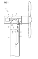
FIG 1 shows a wind turbine with a cooling system, -
FIG 2 shows a second embodiment of the cooling system, -
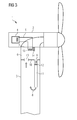
FIG 3 shows a third embodiment of the cooling system. -
FIG 1 shows a wind turbine with a cooling system.FIG 1 shows awind turbine 1 with a cooling system. The wind turbine comprises anacelle 2 and atower 3, whereby thenacelle 2 is arranged rotatable on top of thetower 3. - A
component 4 is arranged in thenacelle 2, whereby thecomponent 4 produces excess heat and needs to be cooled. Thecomponent 4 can either be the generator of the wind turbine or an electric cabinet, like a converter or a transformer. - The
tower 3 comprises achamber 6. Thechamber 6 is arranged in the other part of thetower 3. Thechamber 6 is in direct contact to thenacelle 2, whereby theroof 7 of thechamber 6 is the lower part of thenacelle 2. Thus, theroof 7 of thechamber 6 rotates together with thenacelle 2. - The
floor 18 of thechamber 6 is a platform in thetower 3, preferably the yaw platform of thewind turbine 1. - A
first cooling system 5 is connected to thecomponent 4 in a way that it transfers the heat from thecomponent 4 into thechamber 6. - The
first cooling system 5 uses air as a cooling medium. The air flows through an opening 16 from thechamber 6 to thecomponent 4. The air picks up the heat of the component and flows through a pipe and anopening 17 back into thechamber 6. - Thus, the heat of the
component 4 is transferred to thechamber 6. Aventilator 15 is arranged at theopening 17 to move the air from thecomponent 4 into thechamber 6. - The heat in the
chamber 6 is removed by asecond cooling system 8. Thesecond cooling system 8 comprises anopening 9 in thefloor 18 of thechamber 6. - A
pipe 11 is connected as an air-duct to theopening 9. Aventilator 12 is arranged within the air duct. Aventilator 12 moves the warm air from thechamber 6 through theduct 11 into thetower 3. Preferably, theair duct 11 is more than 20 m long. - The warm air that exits the
air duct 11 at a lower level in thetower 3, flows upwards inside thetower 3 and is cooled as it flows along the wall of thetower 3. The air enters thechamber 6 through anopening 10 in thefloor 18 of thechamber 6. - Thus, the heat of the
component 4 is transferred through thechamber 6 into thetower 3 and thetower 3 is used as a heat sink. In thetower 3, the heat of the warm air is transferred to the tower wall and the tower wall is cooled by the wind and the ambient air. -
FIG 2 shows a second embodiment of the cooling system.FIG 2 shows a second embodiment of the cooling system in thewind turbine 1. Thewind turbine 1 comprises anacelle 2 that is arranged rotatable on top of atower 3. - A
component 4 is arranged in thenacelle 2. Thecomponent 4 can be a generator, a transformer, a converter or an electrical cabinet inside thenacelle 2. Thecomponent 4 produces excess heat that need to be cooled. - The
first cooling system 5 is installed to cool thecomponent 4. Thetower 3 comprises achamber 6, whereby the roof of the chamber is the lower part of thenacelle 2. Thus, the roof of thechamber 6 rotates together with thenacelle 2. - The
floor 18 of thechamber 6 is a platform in the tower in general the yaw platform. The wall of thechamber 6 is built by the wall of thetower 3. - Air from the chamber is flowing through an
opening 6 and theroof 7 of the chamber to thecomponent 4 in thenacelle 2. The air removes the heat from thecomponent 4 and flows through a tube and theopening 15 back into thechamber 6. Aventilator 17 is arranged at theopening 15 to move the air through the first cooling system. - The hot air in the
chamber 6 is moved by aventilator 12 through anopening 9 in thefloor 18 of thechamber 6. Theventilator 12 forces the air from thechamber 6 into the lower part of thetower 3. On the way down into the tower, the air flows along the tower wall and transfers its thermal energy to the tower wall. - Further down in the
tower 3, the air flows through apipe 11, that is used as an air-duct, back through anopening 10 in thefloor 18 of thechamber 6 into the chamber. - The
ventilator 12, thepipe 11 and theopenings second cooling system 8. Thesecond cooling system 8 transfers the warm air from thechamber 6 into thetower 3. Thetower 3 is used as a heat sink for the warm air of thechamber 6. Thus, the air in thechamber 6 gets cooled by thesecond cooling system 8. -
FIG 3 shows a third embodiment of the cooling system.FIG 3 shows a third embodiment of the cooling system of awind turbine 1. Thewind turbine 1 comprises anacelle 2 and atower 3, whereby thenacelle 2 is arranged rotatable on top of thetower 3. - A
component 4 is arranged in thenacelle 2. Thecomponent 4 produces excess heat and needs to be cooled. Afirst cooling system 5 is connected to thecomponent 4 to transfer the heat from thecomponent 4 into thetower 3. - The
tower 3 comprises achamber 6 in the upper part of the tower, whereby theroof 7 of thechamber 6 is the lower part of thenacelle 2. Thus, theroof 7 of thechamber 6 rotates together with thenacelle 2. The wall of thechambers 6 is built by the wall of thetower 3. - The
floor 18 of thechamber 6 is a platform in the tower, in general the yaw platform. - The
first cooling system 5 comprises aheat exchanger 13 that transfers the heat from thecomponent 4 into thechamber 6 in thetower 3. - A
ventilator 14 is arranged to move the air along theheat exchanger 13 to transfer the heat from thefirst cooling system 5 to the air in thechamber 6. The air in thechamber 6 is cooled by asecond cooling system 8. - The
second cooling system 8 comprises anopening 9, aventilator 12, apipe 11, thetower 3, and anopening 10. The warm air of thechamber 6 is flowing through theopening 9 and through thepipe 11. Aventilator 12 is arranged within thepipe 11 to move the air from thechamber 6 through thepipe 11 into thetower 3. - The air that exits the
pipe 11 flows upward inside thetower 3 and transfers its thermal energy to the tower wall. The tower wall is then cooled by the wind and the ambient air outside of the tower. Thus, thetower 3 is used as a heat sink in thesecond cooling system 8. The cool air from the tower moves through theopening 10 back into thechamber 6. - The
first cooling system 5 is built as a closed cooling circuit. As a cooling fluid in thefirst cooling system 5 air, water or oil can be used. - Although the present invention has been described in detail with reference to the preferred embodiment, it is to be understood that the present invention is not limited by the disclosed examples, and that numerous additional modifications and variations could be made thereto by a person skilled in the art without departing from the scope of the invention.
- It should be noted that the use of "a" or "an" throughout this application does not exclude a plurality, and "comprising" does not exclude other steps or elements. Also elements described in association with different embodiments may be combined. It should also be noted that reference signs in the claims should not be construed as limiting the scope of the claims.
Claims (14)
- Wind turbine cooling system- whereby a wind turbine (1) comprises a nacelle (2) and a tower (3), and the nacelle (2) is rotatable arranged on top of the tower (3),- whereby a component (4) is arranged in the nacelle (2) and the component (4) emits excess heat and a first cooling system (5) is coupled with the component (4) in a way to cool the component (4) in the nacelle (2),- whereby the tower (3) comprises a chamber (6) that is arranged in the upper part of the tower (3), directly below and in contact with the nacelle (2),- whereby the roof (7) of the chamber (6) is the bottom part of the nacelle (2) and the roof (7) of the chamber (6) is rotatable together with the nacelle (2) in respect to the tower (3),- whereby the first cooling system (5) is connected to the chamber (6) through the roof (7) of the chamber (6), so that the heat from the first cooling system (5) is transferred to the air in the chamber (6),- whereby the chamber (6) is cooled by a second cooling system (8),- whereby the chamber (6) comprises a floor and the second cooling system (8) comprises a connection (9, 10) between the chamber (6) and the tower (3) through the floor, to guide the warm air from the chamber (6) into the tower (3), so that the warm air flows along the wall of the tower and is cooled by the tower wall, so that the tower (3) is used as a heat sink,- so that transportation of heat from the first cooling system to the tower is independent from the rotation or orientation of the nacelle (2) in respect to the tower (3).
- Wind turbine cooling system according to claim 1, whereby the chamber (6) comprises a floor and a first opening (9) to allow air from the chamber (6) to flow into the tower (3) and a second opening (10) to allow cool air from the tower (3) to flow into the chamber (6) are arranged in the floor of the chamber.
- Wind turbine cooling system according to claim 2, whereby an air duct (11) is connected to the first opening (9) to guide the warm air from the chamber down into the tower (3), so that the air flows along the tower wall on the way up towards the chamber and cools at the tower wall.
- Wind turbine cooling system according to claim 2, whereby an air duct (11) is connected to the second opening (10), so that the warm air flows through the first opening (9) into the tower, flows down along the tower wall and cools at the tower wall, and that the cool air in the tower is guided into the chamber (6) through the air duct (11) and the second opening (10).
- Wind turbine cooling system according to one of the claims 2 or 3, whereby a ventilator (12) is arranged at one of the openings (9, 10) so that the air is moved through the tower (3).
- Wind turbine cooling system according to one of the claims 2 to 4, whereby the air duct (11) is a pipe.
- Wind turbine cooling system according to claim 6, whereby the pipe is more than 20 meters long.
- Wind turbine cooling system according to one of the preceding claims, whereby the first cooling system (5) comprises a heat exchanger (13) that is arranged in the chamber (6), to transfer the heat from the first cooling system (5) to the air in the chamber (6).
- Wind turbine cooling system according to one of the preceding claims, whereby a ventilator (14) is arranged at the heat exchanger (13) to transfer the heat of the first cooling system to the air in the chamber(6).
- Wind turbine cooling system according to one of the claims 1 to 5, whereby air is used as a cooling medium in the first cooling system (5).
- Wind turbine cooling system according to claim 10, whereby the first cooling system (5) is connected to the chamber (6) in a way that warm air from the first cooling system (5) flows into the chamber (6) through an opening (15) in the roof (7) of the chamber (6) and air from the chamber (6) flows into the first cooling system (5) of the nacelle (2) through an opening (16) in the roof (7) of the chamber (6).
- Wind turbine cooling system according to one of the claims 10 or 11, whereby the first cooling system (5) comprises a ventilator (17), so that air from the chamber (6) is moved through the first cooling system (5).
- Wind turbine cooling system according to one of the preceding claims, whereby the bottom of the chamber (6) is the yaw platform (18) of the tower (2).
- Method to cool a component (4) in the nacelle (2) of a wind turbine (1),- whereby a wind turbine (1) comprises a nacelle (2) and a tower (3), and the nacelle (2) is rotatable arranged on top of the tower (3),- whereby a component (4) is arranged in the nacelle (2) and the component (4) emits excess heat and a first cooling system (5) is coupled with the component (4) in a way to cool the component (4) in the nacelle (2),- whereby the tower (3) comprises a chamber (6) that is arranged in the upper part of the tower (3), directly below and in contact with the nacelle (2), so that the roof (7) of the chamber (6) is the bottom part of the nacelle (2) and that the roof (7) of the chamber (6) is rotatable together with the nacelle (2) in respect to the tower (3),
comprising the steps of- transferring the heat from the component (4) in the nacelle (2) into the chamber (6) by a first cooling system (5),- cooling the air in the chamber (6) by forcing the air into the tower (3), where the air flows along the tower wall and transfers the heat to the tower wall.
Priority Applications (2)
| Application Number | Priority Date | Filing Date | Title |
|---|---|---|---|
| EP13178485.2A EP2832992B1 (en) | 2013-07-30 | 2013-07-30 | Wind turbine comprising a cooling system |
| DK13178485.2T DK2832992T3 (en) | 2013-07-30 | 2013-07-30 | Wind turbine comprising a cooling system |
Applications Claiming Priority (1)
| Application Number | Priority Date | Filing Date | Title |
|---|---|---|---|
| EP13178485.2A EP2832992B1 (en) | 2013-07-30 | 2013-07-30 | Wind turbine comprising a cooling system |
Publications (2)
| Publication Number | Publication Date |
|---|---|
| EP2832992A1 true EP2832992A1 (en) | 2015-02-04 |
| EP2832992B1 EP2832992B1 (en) | 2017-12-13 |
Family
ID=48914072
Family Applications (1)
| Application Number | Title | Priority Date | Filing Date |
|---|---|---|---|
| EP13178485.2A Active EP2832992B1 (en) | 2013-07-30 | 2013-07-30 | Wind turbine comprising a cooling system |
Country Status (2)
| Country | Link |
|---|---|
| EP (1) | EP2832992B1 (en) |
| DK (1) | DK2832992T3 (en) |
Cited By (1)
| Publication number | Priority date | Publication date | Assignee | Title |
|---|---|---|---|---|
| JP2015206327A (en) * | 2014-04-23 | 2015-11-19 | 株式会社日立製作所 | Wind power generation facility |
Citations (6)
| Publication number | Priority date | Publication date | Assignee | Title |
|---|---|---|---|---|
| WO2001006121A1 (en) | 1999-07-14 | 2001-01-25 | Aloys Wobben | Wind energy facility with a closed cooling circuit |
| GR1005990B (en) * | 2007-02-16 | 2008-07-22 | Γεωργιος Πεχλιβανογλου | Cooling system for wind generators. |
| WO2010069954A1 (en) * | 2008-12-17 | 2010-06-24 | Xemc Darwind Bv | Wind turbine comprising a cooling circuit |
| EP2302214A2 (en) * | 2009-09-25 | 2011-03-30 | General Electric Company | Method and system for cooling a wind turbine structure |
| US20110133483A1 (en) * | 2009-12-04 | 2011-06-09 | Mitsubishi Heavy Industries, Ltd. | Wind power generator |
| CN201908789U (en) * | 2011-01-25 | 2011-07-27 | 湘电风能有限公司 | Radiating device of wind-driven generator |
-
2013
- 2013-07-30 DK DK13178485.2T patent/DK2832992T3/en active
- 2013-07-30 EP EP13178485.2A patent/EP2832992B1/en active Active
Patent Citations (6)
| Publication number | Priority date | Publication date | Assignee | Title |
|---|---|---|---|---|
| WO2001006121A1 (en) | 1999-07-14 | 2001-01-25 | Aloys Wobben | Wind energy facility with a closed cooling circuit |
| GR1005990B (en) * | 2007-02-16 | 2008-07-22 | Γεωργιος Πεχλιβανογλου | Cooling system for wind generators. |
| WO2010069954A1 (en) * | 2008-12-17 | 2010-06-24 | Xemc Darwind Bv | Wind turbine comprising a cooling circuit |
| EP2302214A2 (en) * | 2009-09-25 | 2011-03-30 | General Electric Company | Method and system for cooling a wind turbine structure |
| US20110133483A1 (en) * | 2009-12-04 | 2011-06-09 | Mitsubishi Heavy Industries, Ltd. | Wind power generator |
| CN201908789U (en) * | 2011-01-25 | 2011-07-27 | 湘电风能有限公司 | Radiating device of wind-driven generator |
Cited By (1)
| Publication number | Priority date | Publication date | Assignee | Title |
|---|---|---|---|---|
| JP2015206327A (en) * | 2014-04-23 | 2015-11-19 | 株式会社日立製作所 | Wind power generation facility |
Also Published As
| Publication number | Publication date |
|---|---|
| DK2832992T3 (en) | 2018-01-22 |
| EP2832992B1 (en) | 2017-12-13 |
Similar Documents
| Publication | Publication Date | Title |
|---|---|---|
| US9228566B2 (en) | Wind turbine comprising a cooling circuit | |
| CN1982702B (en) | Wind energy turbine | |
| CN205207057U (en) | Wind generating set cooling system and wind generating set | |
| JP5284386B2 (en) | Wind power generation equipment | |
| CN102822514B (en) | Cooling system for a wind turbine | |
| EP2007184A2 (en) | System for integrated thermal management and method for the same | |
| EP2827012B1 (en) | Cooling of a bearing for a wind turbine | |
| JP2009531579A (en) | Thermal management system for wind turbine | |
| EP2530312A2 (en) | Cooling and climate control system and method for an offshore wind turbine | |
| JP2011069363A (en) | Method and system for cooling wind turbine structure | |
| EP2573389B1 (en) | Cooling and climate control system and method for a wind turbine | |
| EP1318299A1 (en) | Bulb turbine-generator unit | |
| EP2391821A2 (en) | Wind turbine nacelle with cooler top. | |
| CN102128139A (en) | Wind driven generator cooled by tower barrel wall | |
| CN102094763A (en) | Offshore wind turbine | |
| EP2391823B1 (en) | Wind turbine with cooler top | |
| JP6383562B2 (en) | Wind power generation equipment | |
| JP5912518B2 (en) | Stationary equipment | |
| EP2832992B1 (en) | Wind turbine comprising a cooling system | |
| EP2450570B1 (en) | Cooling arrangement for a wind turbine | |
| KR101434443B1 (en) | Apparatus for nacelle air cooling using by heat exchanger | |
| CN104405586A (en) | Overland direct driving blower | |
| JP6230424B2 (en) | Wind power generator | |
| JP2019527029A (en) | Method for cooling the rotor of a generator | |
| CN104564538B (en) | Heat abstractor and wind power generating set for wind power generating set |
Legal Events
| Date | Code | Title | Description |
|---|---|---|---|
| 17P | Request for examination filed |
Effective date: 20130730 |
|
| AK | Designated contracting states |
Kind code of ref document: A1 Designated state(s): AL AT BE BG CH CY CZ DE DK EE ES FI FR GB GR HR HU IE IS IT LI LT LU LV MC MK MT NL NO PL PT RO RS SE SI SK SM TR |
|
| AX | Request for extension of the european patent |
Extension state: BA ME |
|
| PUAI | Public reference made under article 153(3) epc to a published international application that has entered the european phase |
Free format text: ORIGINAL CODE: 0009012 |
|
| R17P | Request for examination filed (corrected) |
Effective date: 20150803 |
|
| RBV | Designated contracting states (corrected) |
Designated state(s): AL AT BE BG CH CY CZ DE DK EE ES FI FR GB GR HR HU IE IS IT LI LT LU LV MC MK MT NL NO PL PT RO RS SE SI SK SM TR |
|
| REG | Reference to a national code |
Ref country code: DE Ref legal event code: R079 Ref document number: 602013030689 Country of ref document: DE Free format text: PREVIOUS MAIN CLASS: F03D0011000000 Ipc: F03D0080600000 |
|
| GRAP | Despatch of communication of intention to grant a patent |
Free format text: ORIGINAL CODE: EPIDOSNIGR1 |
|
| RIC1 | Information provided on ipc code assigned before grant |
Ipc: F03D 80/60 20160101AFI20170627BHEP |
|
| INTG | Intention to grant announced |
Effective date: 20170720 |
|
| RAP1 | Party data changed (applicant data changed or rights of an application transferred) |
Owner name: SIEMENS AKTIENGESELLSCHAFT |
|
| GRAS | Grant fee paid |
Free format text: ORIGINAL CODE: EPIDOSNIGR3 |
|
| GRAA | (expected) grant |
Free format text: ORIGINAL CODE: 0009210 |
|
| AK | Designated contracting states |
Kind code of ref document: B1 Designated state(s): AL AT BE BG CH CY CZ DE DK EE ES FI FR GB GR HR HU IE IS IT LI LT LU LV MC MK MT NL NO PL PT RO RS SE SI SK SM TR |
|
| REG | Reference to a national code |
Ref country code: GB Ref legal event code: FG4D |
|
| REG | Reference to a national code |
Ref country code: AT Ref legal event code: REF Ref document number: 954652 Country of ref document: AT Kind code of ref document: T Effective date: 20171215 Ref country code: CH Ref legal event code: EP |
|
| REG | Reference to a national code |
Ref country code: IE Ref legal event code: FG4D |
|
| REG | Reference to a national code |
Ref country code: DE Ref legal event code: R096 Ref document number: 602013030689 Country of ref document: DE |
|
| REG | Reference to a national code |
Ref country code: DK Ref legal event code: T3 Effective date: 20180119 |
|
| REG | Reference to a national code |
Ref country code: NL Ref legal event code: MP Effective date: 20171213 |
|
| REG | Reference to a national code |
Ref country code: LT Ref legal event code: MG4D |
|
| PG25 | Lapsed in a contracting state [announced via postgrant information from national office to epo] |
Ref country code: NO Free format text: LAPSE BECAUSE OF FAILURE TO SUBMIT A TRANSLATION OF THE DESCRIPTION OR TO PAY THE FEE WITHIN THE PRESCRIBED TIME-LIMIT Effective date: 20180313 Ref country code: FI Free format text: LAPSE BECAUSE OF FAILURE TO SUBMIT A TRANSLATION OF THE DESCRIPTION OR TO PAY THE FEE WITHIN THE PRESCRIBED TIME-LIMIT Effective date: 20171213 Ref country code: LT Free format text: LAPSE BECAUSE OF FAILURE TO SUBMIT A TRANSLATION OF THE DESCRIPTION OR TO PAY THE FEE WITHIN THE PRESCRIBED TIME-LIMIT Effective date: 20171213 Ref country code: SE Free format text: LAPSE BECAUSE OF FAILURE TO SUBMIT A TRANSLATION OF THE DESCRIPTION OR TO PAY THE FEE WITHIN THE PRESCRIBED TIME-LIMIT Effective date: 20171213 |
|
| REG | Reference to a national code |
Ref country code: AT Ref legal event code: MK05 Ref document number: 954652 Country of ref document: AT Kind code of ref document: T Effective date: 20171213 |
|
| PG25 | Lapsed in a contracting state [announced via postgrant information from national office to epo] |
Ref country code: HR Free format text: LAPSE BECAUSE OF FAILURE TO SUBMIT A TRANSLATION OF THE DESCRIPTION OR TO PAY THE FEE WITHIN THE PRESCRIBED TIME-LIMIT Effective date: 20171213 Ref country code: RS Free format text: LAPSE BECAUSE OF FAILURE TO SUBMIT A TRANSLATION OF THE DESCRIPTION OR TO PAY THE FEE WITHIN THE PRESCRIBED TIME-LIMIT Effective date: 20171213 Ref country code: BG Free format text: LAPSE BECAUSE OF FAILURE TO SUBMIT A TRANSLATION OF THE DESCRIPTION OR TO PAY THE FEE WITHIN THE PRESCRIBED TIME-LIMIT Effective date: 20180313 Ref country code: LV Free format text: LAPSE BECAUSE OF FAILURE TO SUBMIT A TRANSLATION OF THE DESCRIPTION OR TO PAY THE FEE WITHIN THE PRESCRIBED TIME-LIMIT Effective date: 20171213 Ref country code: GR Free format text: LAPSE BECAUSE OF FAILURE TO SUBMIT A TRANSLATION OF THE DESCRIPTION OR TO PAY THE FEE WITHIN THE PRESCRIBED TIME-LIMIT Effective date: 20180314 |
|
| PG25 | Lapsed in a contracting state [announced via postgrant information from national office to epo] |
Ref country code: NL Free format text: LAPSE BECAUSE OF FAILURE TO SUBMIT A TRANSLATION OF THE DESCRIPTION OR TO PAY THE FEE WITHIN THE PRESCRIBED TIME-LIMIT Effective date: 20171213 |
|
| PG25 | Lapsed in a contracting state [announced via postgrant information from national office to epo] |
Ref country code: SK Free format text: LAPSE BECAUSE OF FAILURE TO SUBMIT A TRANSLATION OF THE DESCRIPTION OR TO PAY THE FEE WITHIN THE PRESCRIBED TIME-LIMIT Effective date: 20171213 Ref country code: CY Free format text: LAPSE BECAUSE OF FAILURE TO SUBMIT A TRANSLATION OF THE DESCRIPTION OR TO PAY THE FEE WITHIN THE PRESCRIBED TIME-LIMIT Effective date: 20171213 Ref country code: CZ Free format text: LAPSE BECAUSE OF FAILURE TO SUBMIT A TRANSLATION OF THE DESCRIPTION OR TO PAY THE FEE WITHIN THE PRESCRIBED TIME-LIMIT Effective date: 20171213 Ref country code: EE Free format text: LAPSE BECAUSE OF FAILURE TO SUBMIT A TRANSLATION OF THE DESCRIPTION OR TO PAY THE FEE WITHIN THE PRESCRIBED TIME-LIMIT Effective date: 20171213 Ref country code: ES Free format text: LAPSE BECAUSE OF FAILURE TO SUBMIT A TRANSLATION OF THE DESCRIPTION OR TO PAY THE FEE WITHIN THE PRESCRIBED TIME-LIMIT Effective date: 20171213 |
|
| PG25 | Lapsed in a contracting state [announced via postgrant information from national office to epo] |
Ref country code: SM Free format text: LAPSE BECAUSE OF FAILURE TO SUBMIT A TRANSLATION OF THE DESCRIPTION OR TO PAY THE FEE WITHIN THE PRESCRIBED TIME-LIMIT Effective date: 20171213 Ref country code: PL Free format text: LAPSE BECAUSE OF FAILURE TO SUBMIT A TRANSLATION OF THE DESCRIPTION OR TO PAY THE FEE WITHIN THE PRESCRIBED TIME-LIMIT Effective date: 20171213 Ref country code: IT Free format text: LAPSE BECAUSE OF FAILURE TO SUBMIT A TRANSLATION OF THE DESCRIPTION OR TO PAY THE FEE WITHIN THE PRESCRIBED TIME-LIMIT Effective date: 20171213 Ref country code: AT Free format text: LAPSE BECAUSE OF FAILURE TO SUBMIT A TRANSLATION OF THE DESCRIPTION OR TO PAY THE FEE WITHIN THE PRESCRIBED TIME-LIMIT Effective date: 20171213 Ref country code: RO Free format text: LAPSE BECAUSE OF FAILURE TO SUBMIT A TRANSLATION OF THE DESCRIPTION OR TO PAY THE FEE WITHIN THE PRESCRIBED TIME-LIMIT Effective date: 20171213 Ref country code: IS Free format text: LAPSE BECAUSE OF FAILURE TO SUBMIT A TRANSLATION OF THE DESCRIPTION OR TO PAY THE FEE WITHIN THE PRESCRIBED TIME-LIMIT Effective date: 20180413 |
|
| REG | Reference to a national code |
Ref country code: DE Ref legal event code: R097 Ref document number: 602013030689 Country of ref document: DE |
|
| PLBE | No opposition filed within time limit |
Free format text: ORIGINAL CODE: 0009261 |
|
| STAA | Information on the status of an ep patent application or granted ep patent |
Free format text: STATUS: NO OPPOSITION FILED WITHIN TIME LIMIT |
|
| 26N | No opposition filed |
Effective date: 20180914 |
|
| PG25 | Lapsed in a contracting state [announced via postgrant information from national office to epo] |
Ref country code: SI Free format text: LAPSE BECAUSE OF FAILURE TO SUBMIT A TRANSLATION OF THE DESCRIPTION OR TO PAY THE FEE WITHIN THE PRESCRIBED TIME-LIMIT Effective date: 20171213 |
|
| REG | Reference to a national code |
Ref country code: CH Ref legal event code: PL |
|
| PG25 | Lapsed in a contracting state [announced via postgrant information from national office to epo] |
Ref country code: LU Free format text: LAPSE BECAUSE OF NON-PAYMENT OF DUE FEES Effective date: 20180730 Ref country code: MC Free format text: LAPSE BECAUSE OF FAILURE TO SUBMIT A TRANSLATION OF THE DESCRIPTION OR TO PAY THE FEE WITHIN THE PRESCRIBED TIME-LIMIT Effective date: 20171213 |
|
| REG | Reference to a national code |
Ref country code: BE Ref legal event code: MM Effective date: 20180731 |
|
| PG25 | Lapsed in a contracting state [announced via postgrant information from national office to epo] |
Ref country code: FR Free format text: LAPSE BECAUSE OF NON-PAYMENT OF DUE FEES Effective date: 20180731 Ref country code: LI Free format text: LAPSE BECAUSE OF NON-PAYMENT OF DUE FEES Effective date: 20180731 Ref country code: CH Free format text: LAPSE BECAUSE OF NON-PAYMENT OF DUE FEES Effective date: 20180731 |
|
| REG | Reference to a national code |
Ref country code: IE Ref legal event code: MM4A |
|
| PG25 | Lapsed in a contracting state [announced via postgrant information from national office to epo] |
Ref country code: BE Free format text: LAPSE BECAUSE OF NON-PAYMENT OF DUE FEES Effective date: 20180731 |
|
| REG | Reference to a national code |
Ref country code: DE Ref legal event code: R081 Ref document number: 602013030689 Country of ref document: DE Owner name: SIEMENS GAMESA RENEWABLE ENERGY A/S, DK Free format text: FORMER OWNER: SIEMENS AKTIENGESELLSCHAFT, 80333 MUENCHEN, DE |
|
| PG25 | Lapsed in a contracting state [announced via postgrant information from national office to epo] |
Ref country code: IE Free format text: LAPSE BECAUSE OF NON-PAYMENT OF DUE FEES Effective date: 20180730 |
|
| REG | Reference to a national code |
Ref country code: GB Ref legal event code: 732E Free format text: REGISTERED BETWEEN 20191128 AND 20191204 |
|
| PG25 | Lapsed in a contracting state [announced via postgrant information from national office to epo] |
Ref country code: MT Free format text: LAPSE BECAUSE OF NON-PAYMENT OF DUE FEES Effective date: 20180730 |
|
| PG25 | Lapsed in a contracting state [announced via postgrant information from national office to epo] |
Ref country code: TR Free format text: LAPSE BECAUSE OF FAILURE TO SUBMIT A TRANSLATION OF THE DESCRIPTION OR TO PAY THE FEE WITHIN THE PRESCRIBED TIME-LIMIT Effective date: 20171213 |
|
| PG25 | Lapsed in a contracting state [announced via postgrant information from national office to epo] |
Ref country code: HU Free format text: LAPSE BECAUSE OF FAILURE TO SUBMIT A TRANSLATION OF THE DESCRIPTION OR TO PAY THE FEE WITHIN THE PRESCRIBED TIME-LIMIT; INVALID AB INITIO Effective date: 20130730 Ref country code: PT Free format text: LAPSE BECAUSE OF FAILURE TO SUBMIT A TRANSLATION OF THE DESCRIPTION OR TO PAY THE FEE WITHIN THE PRESCRIBED TIME-LIMIT Effective date: 20171213 |
|
| PG25 | Lapsed in a contracting state [announced via postgrant information from national office to epo] |
Ref country code: MK Free format text: LAPSE BECAUSE OF NON-PAYMENT OF DUE FEES Effective date: 20171213 |
|
| PG25 | Lapsed in a contracting state [announced via postgrant information from national office to epo] |
Ref country code: AL Free format text: LAPSE BECAUSE OF FAILURE TO SUBMIT A TRANSLATION OF THE DESCRIPTION OR TO PAY THE FEE WITHIN THE PRESCRIBED TIME-LIMIT Effective date: 20171213 |
|
| PGFP | Annual fee paid to national office [announced via postgrant information from national office to epo] |
Ref country code: GB Payment date: 20230724 Year of fee payment: 11 |
|
| PGFP | Annual fee paid to national office [announced via postgrant information from national office to epo] |
Ref country code: DK Payment date: 20230724 Year of fee payment: 11 Ref country code: DE Payment date: 20230720 Year of fee payment: 11 |