EP2832985A1 - Air cleaner device for vehicle - Google Patents
Air cleaner device for vehicle Download PDFInfo
- Publication number
- EP2832985A1 EP2832985A1 EP20140170076 EP14170076A EP2832985A1 EP 2832985 A1 EP2832985 A1 EP 2832985A1 EP 20140170076 EP20140170076 EP 20140170076 EP 14170076 A EP14170076 A EP 14170076A EP 2832985 A1 EP2832985 A1 EP 2832985A1
- Authority
- EP
- European Patent Office
- Prior art keywords
- air cleaner
- intake
- intake ducts
- vehicle
- cleaner case
- Prior art date
- Legal status (The legal status is an assumption and is not a legal conclusion. Google has not performed a legal analysis and makes no representation as to the accuracy of the status listed.)
- Granted
Links
Images


Classifications
-
- F—MECHANICAL ENGINEERING; LIGHTING; HEATING; WEAPONS; BLASTING
- F02—COMBUSTION ENGINES; HOT-GAS OR COMBUSTION-PRODUCT ENGINE PLANTS
- F02M—SUPPLYING COMBUSTION ENGINES IN GENERAL WITH COMBUSTIBLE MIXTURES OR CONSTITUENTS THEREOF
- F02M35/00—Combustion-air cleaners, air intakes, intake silencers, or induction systems specially adapted for, or arranged on, internal-combustion engines
- F02M35/02—Air cleaners
- F02M35/0201—Housings; Casings; Frame constructions; Lids; Manufacturing or assembling thereof
-
- B—PERFORMING OPERATIONS; TRANSPORTING
- B62—LAND VEHICLES FOR TRAVELLING OTHERWISE THAN ON RAILS
- B62K—CYCLES; CYCLE FRAMES; CYCLE STEERING DEVICES; RIDER-OPERATED TERMINAL CONTROLS SPECIALLY ADAPTED FOR CYCLES; CYCLE AXLE SUSPENSIONS; CYCLE SIDE-CARS, FORECARS, OR THE LIKE
- B62K11/00—Motorcycles, engine-assisted cycles or motor scooters with one or two wheels
- B62K11/02—Frames
- B62K11/04—Frames characterised by the engine being between front and rear wheels
-
- B—PERFORMING OPERATIONS; TRANSPORTING
- B62—LAND VEHICLES FOR TRAVELLING OTHERWISE THAN ON RAILS
- B62K—CYCLES; CYCLE FRAMES; CYCLE STEERING DEVICES; RIDER-OPERATED TERMINAL CONTROLS SPECIALLY ADAPTED FOR CYCLES; CYCLE AXLE SUSPENSIONS; CYCLE SIDE-CARS, FORECARS, OR THE LIKE
- B62K19/00—Cycle frames
- B62K19/48—Fairings forming part of frame
-
- F—MECHANICAL ENGINEERING; LIGHTING; HEATING; WEAPONS; BLASTING
- F02—COMBUSTION ENGINES; HOT-GAS OR COMBUSTION-PRODUCT ENGINE PLANTS
- F02M—SUPPLYING COMBUSTION ENGINES IN GENERAL WITH COMBUSTIBLE MIXTURES OR CONSTITUENTS THEREOF
- F02M35/00—Combustion-air cleaners, air intakes, intake silencers, or induction systems specially adapted for, or arranged on, internal-combustion engines
- F02M35/02—Air cleaners
- F02M35/0201—Housings; Casings; Frame constructions; Lids; Manufacturing or assembling thereof
- F02M35/0204—Housings; Casings; Frame constructions; Lids; Manufacturing or assembling thereof for connecting or joining to other devices, e.g. pipes
-
- F—MECHANICAL ENGINEERING; LIGHTING; HEATING; WEAPONS; BLASTING
- F02—COMBUSTION ENGINES; HOT-GAS OR COMBUSTION-PRODUCT ENGINE PLANTS
- F02M—SUPPLYING COMBUSTION ENGINES IN GENERAL WITH COMBUSTIBLE MIXTURES OR CONSTITUENTS THEREOF
- F02M35/00—Combustion-air cleaners, air intakes, intake silencers, or induction systems specially adapted for, or arranged on, internal-combustion engines
- F02M35/02—Air cleaners
- F02M35/0201—Housings; Casings; Frame constructions; Lids; Manufacturing or assembling thereof
- F02M35/0205—Details, e.g. sensors or measuring devices
-
- F—MECHANICAL ENGINEERING; LIGHTING; HEATING; WEAPONS; BLASTING
- F02—COMBUSTION ENGINES; HOT-GAS OR COMBUSTION-PRODUCT ENGINE PLANTS
- F02M—SUPPLYING COMBUSTION ENGINES IN GENERAL WITH COMBUSTIBLE MIXTURES OR CONSTITUENTS THEREOF
- F02M35/00—Combustion-air cleaners, air intakes, intake silencers, or induction systems specially adapted for, or arranged on, internal-combustion engines
- F02M35/02—Air cleaners
- F02M35/04—Air cleaners specially arranged with respect to engine, to intake system or specially adapted to vehicle; Mounting thereon ; Combinations with other devices
- F02M35/048—Arranging or mounting on or with respect to engines or vehicle bodies
-
- F—MECHANICAL ENGINEERING; LIGHTING; HEATING; WEAPONS; BLASTING
- F02—COMBUSTION ENGINES; HOT-GAS OR COMBUSTION-PRODUCT ENGINE PLANTS
- F02M—SUPPLYING COMBUSTION ENGINES IN GENERAL WITH COMBUSTIBLE MIXTURES OR CONSTITUENTS THEREOF
- F02M35/00—Combustion-air cleaners, air intakes, intake silencers, or induction systems specially adapted for, or arranged on, internal-combustion engines
- F02M35/10—Air intakes; Induction systems
- F02M35/10006—Air intakes; Induction systems characterised by the position of elements of the air intake system in direction of the air intake flow, i.e. between ambient air inlet and supply to the combustion chamber
- F02M35/10013—Means upstream of the air filter; Connection to the ambient air
-
- F—MECHANICAL ENGINEERING; LIGHTING; HEATING; WEAPONS; BLASTING
- F02—COMBUSTION ENGINES; HOT-GAS OR COMBUSTION-PRODUCT ENGINE PLANTS
- F02M—SUPPLYING COMBUSTION ENGINES IN GENERAL WITH COMBUSTIBLE MIXTURES OR CONSTITUENTS THEREOF
- F02M35/00—Combustion-air cleaners, air intakes, intake silencers, or induction systems specially adapted for, or arranged on, internal-combustion engines
- F02M35/10—Air intakes; Induction systems
- F02M35/10091—Air intakes; Induction systems characterised by details of intake ducts: shapes; connections; arrangements
- F02M35/10144—Connections of intake ducts to each other or to another device
-
- F—MECHANICAL ENGINEERING; LIGHTING; HEATING; WEAPONS; BLASTING
- F02—COMBUSTION ENGINES; HOT-GAS OR COMBUSTION-PRODUCT ENGINE PLANTS
- F02M—SUPPLYING COMBUSTION ENGINES IN GENERAL WITH COMBUSTIBLE MIXTURES OR CONSTITUENTS THEREOF
- F02M35/00—Combustion-air cleaners, air intakes, intake silencers, or induction systems specially adapted for, or arranged on, internal-combustion engines
- F02M35/16—Combustion-air cleaners, air intakes, intake silencers, or induction systems specially adapted for, or arranged on, internal-combustion engines characterised by use in vehicles
- F02M35/162—Motorcycles; All-terrain vehicles, e.g. quads, snowmobiles; Small vehicles, e.g. forklifts
-
- B—PERFORMING OPERATIONS; TRANSPORTING
- B62—LAND VEHICLES FOR TRAVELLING OTHERWISE THAN ON RAILS
- B62J—CYCLE SADDLES OR SEATS; AUXILIARY DEVICES OR ACCESSORIES SPECIALLY ADAPTED TO CYCLES AND NOT OTHERWISE PROVIDED FOR, e.g. ARTICLE CARRIERS OR CYCLE PROTECTORS
- B62J35/00—Fuel tanks specially adapted for motorcycles or engine-assisted cycles; Arrangements thereof
-
- Y—GENERAL TAGGING OF NEW TECHNOLOGICAL DEVELOPMENTS; GENERAL TAGGING OF CROSS-SECTIONAL TECHNOLOGIES SPANNING OVER SEVERAL SECTIONS OF THE IPC; TECHNICAL SUBJECTS COVERED BY FORMER USPC CROSS-REFERENCE ART COLLECTIONS [XRACs] AND DIGESTS
- Y02—TECHNOLOGIES OR APPLICATIONS FOR MITIGATION OR ADAPTATION AGAINST CLIMATE CHANGE
- Y02T—CLIMATE CHANGE MITIGATION TECHNOLOGIES RELATED TO TRANSPORTATION
- Y02T10/00—Road transport of goods or passengers
- Y02T10/10—Internal combustion engine [ICE] based vehicles
- Y02T10/12—Improving ICE efficiencies
Definitions
- the present invention relates to an air cleaner device for a vehicle having an internal combustion engine, where the air cleaner device is mounted on a vehicle body frame.
- Japanese Patent No. 4128639 discloses an air cleaner device applied to a vehicle (specifically, a motorcycle) having an internal combustion engine and an air cleaner device mounted on a vehicle body frame, wherein an air cleaner case is disposed to the rear of a head pipe, and an intake air duct portion for taking in outside air is provided in the upper part of the air cleaner case.
- the intake air duct portion is disposed on the upper surface of the air cleaner case.
- the air cleaner device may become large in a vertical direction, and a cowl covering the air cleaner device may be increased in height.
- an object of at least the preferred embodiments of the present invention to provide an air cleaner device that is formed in a compact manner while securing an intake capacity, and which can improve intake performance, in a vehicle having an internal combustion engine and the air cleaner device mounted on a vehicle body frame.
- an air cleaner device for a vehicle, the vehicle having an internal combustion engine and the air cleaner device being mounted on a vehicle body frame, the air cleaner device comprising: an air cleaner case having a filter element therein, and being partitioned into a dirty side chamber and a clean side chamber; and a plurality of intake ducts for leading outside air into the dirty side chamber of the air cleaner case, the intake ducts being provided so as to form a left-right pair, wherein the intake ducts forming the left-right pair have intake ports open to the outside of the air cleaner case, the parts of the intake ducts which are housed within the dirty side chamber and which lead to discharge ports having bent portions, and the discharge ports of the intake ducts forming the left-right pair are disposed so as to be oriented toward a lateral centre of the air cleaner case and are longitudinally offset from each other.
- the intake ducts have bent portions housed within the dirty side chamber, and the discharge ports are disposed so as to point towards the centre of the air cleaner case and are longitudinally offset from each other.
- a swirling air flow can be produced within the dirty side chamber during intake, so that the inside of the dirty side chamber can be used uniformly. It is therefore possible to secure an intake capacity and lengths of the intake ducts, and maintain intake performance, while making the air cleaner device compact.
- the intake ducts extend upwardly to the discharge ports from air cleaner case connecting portions attached so as to penetrate the air cleaner case, and are inclined to approach a ceiling of the dirty side chamber, and the discharge ports are oriented downwardly.
- the discharge ports of the intake ducts are disposed in the vicinity of the ceiling within the dirty side chamber, the inside of the dirty side chamber can be used uniformly. It is therefore possible to secure an intake capacity and lengths of the intake ducts, and maintain intake performance, while making the air cleaner device compact.
- a fuel tank is mounted on an upper portion of the vehicle body frame of the vehicle, and the air cleaner case is disposed between a head pipe of the vehicle body frame and the fuel tank, and the intake ports of the intake ducts are open to the rear of the air cleaner case, and are disposed forwardly of a rear end portion of the air cleaner case.
- a fuel tank is mounted on an upper portion of the vehicle body frame of the vehicle, and the air cleaner case is disposed between a head pipe of the vehicle body frame and the fuel tank, and the intake ports of the intake ducts are disposed so as to open to the front of the air cleaner case.
- the air cleaner case is divided into an upper side case half body and a lower side case half body
- the filter element is disposed between the upper side case half body and the lower side case half body
- the dirty side chamber is defined within the upper side case half body
- the clean side chamber is defined within the lower side case half body
- the upper side case half body of the air cleaner case is formed so as to be larger in a lateral direction of the vehicle than a longitudinal direction of the vehicle
- the filter element has a plate shape, and is disposed such its longer axis is parallel to the lateral direction of the vehicle.
- the air cleaner device can be kept longitudinally compact.
- the filter element is plate-shaped, capacity can be secured while the air cleaner device is made vertically compact.
- a connecting tube for leading intake air into the internal combustion engine is connected to the clean side chamber of the air cleaner case, and the discharge ports of the intake ducts at least partly overlap a suction port of the connecting tube in plan view.
- the intake ducts are formed such that the lengths of the intake ducts between air cleaner case connecting portions attached so as to penetrate the air cleaner case and the discharge ports are longer than the lengths of the intake ducts between the air cleaner case connecting portions and the intake ports.
- engaging portions are formed on parts of the intake ducts housed in the dirty side chamber, engagement receiving portions are formed on a ceiling of the dirty side chamber, and the engaging portions are engaged with the engagement receiving portions, whereby the intake ducts are fixed.
- the intake ducts are engaged with and fixed to the ceiling of the dirty side chamber, and so the intake ducts are easily positioned during assembly. Further, the vibration of the intake ducts during suction of the intake air is suppressed, so that an air flow can be led in targeted directions.
- an attachment opening for attaching an intake air temperature sensor is formed in an upper rear portion of the upper side case half body of the air cleaner case, and the intake air temperature sensor is disposed in a vicinity of either one of the discharge ports of the intake ducts forming the left-right pair.
- the intake air temperature sensor can measure the temperature of the intake air that has just been discharged from the discharge port.
- the intake air temperature sensor can be attached in a gap between the air cleaner case and the fuel tank.
- FIGS. 1 to 6 An air cleaner device for a vehicle according to a first embodiment of the present invention will hereinafter be described with reference to FIGS. 1 to 6 .
- the vehicle in the present embodiment is a saddle riding type vehicle having an internal combustion engine and the air cleaner device mounted on a vehicle body frame, and is specifically a motorcycle.
- Terms such as forward, rearward, left, right, up, down and the like in the claims and the description of the present specification should be interpreted with reference to a rider who rides on the vehicle.
- arrow FR indicates the forward direction of the vehicle
- arrow LH indicates the left direction of the vehicle
- arrow RH indicates the right direction of the vehicle
- arrow UP indicates the upward direction of the vehicle.
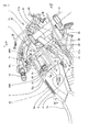
- FIG. 1 is a right side view of a motorcycle 1 according to a first embodiment of the present invention.
- the vehicle body frame 2 of the motorcycle 1 is covered by a vehicle body cover (cowl) 10 made of a synthetic resin.
- the vehicle body frame 2 of the motorcycle 1 includes: a head pipe 20 provided at a front end portion of the vehicle; a pair of left and right main frames 21 branching to left and right from a lower portion of the head pipe 20 and extending rearward while slanting rearwardly downwards; and main reinforcing frames 21 a obliquely connecting an upper portion of the head pipe 20 to the left and right main frames 21.
- the head pipe 20 steerably supports a front fork 12, which in turn supports a front wheel 11.
- Steering handlebars 13 are coupled to an upper portion of the front fork 12.
- Left and right centre frames 22 extend downwardly from the rear ends of the left and right main frames 21, and bend rearwardly.
- Left and right down frames 23 extend rearwardly and steeply downwardly from portions of the left and right main frames 21 in the vicinity of the head pipe 20. Lower end portions of the down frames 23 are connected to down reinforcing frames 23a which extend forwardly and downwardly from longitudinally middle portions of the left and right main frames 21.
- Rear frames (not shown in the Figures) which extend rearwardly from the centre frames 22 are provided to support a seat 14 for occupants.
- the left and right main frames 21, the centre frames 22, and the rear frames are coupled to each other by cross members (not shown in the Figures) to ensure rigidity of the vehicle body frame 2.
- the seat 14 for occupants is configured as a tandem type seat obtained by integrally forming a seat for a driver and a seat for a passenger.
- a fuel tank 6 is mounted in front of the seat 14 for occupants and on upper portions of the pair of left and right main frames 21, in such a manner as to be covered by the vehicle body cover 10.
- the vehicle body cover 10 has an opening to expose a refuelling portion 6a provided on an upper surface of the fuel tank 6.
- the centre frames 22 are provided with a pivot plate 22a.
- the pivot plate 22a rotatably supports a front end of a rear fork 16 via a pivot bolt 15.
- a rear wheel 17 is rotatably supported on a rear end of the rear fork 16.
- the rear fork 16 is vertically swingably supported via a rear cushion (not shown in the Figures).
- An internal combustion engine 3 of the motorcycle 1 is suspended on the vehicle body frame 2 at lower end portions of the down frames 23, connecting portions between the main frames 21 and the down reinforcing frames 23a, and upper portions of the centre frames 22.
- the internal combustion engine 3 forms a so-called power unit, which integrally includes a transmission 5 within a crankcase 4.
- a crankshaft 41 and a transmission shaft are housed in the crankcase 4.
- the internal combustion engine 3 is mounted in the motorcycle 1 with the crankshaft 41 oriented in a lateral (left-right) direction of the vehicle.
- the power of the internal combustion engine 3 is transmitted from an output shaft 42 projecting from the left of the crankcase 4 to the rear wheel 17 via a chain drive mechanism 43.
- the internal combustion engine 3 is an in-line two-cylinder water-cooled four-stroke-cycle engine, having a cylinder portion 30 extending upwardly from an upper front portion of the crankcase 4 and inclined forwardly.
- the cylinder portion 30 includes: a cylinder block 31 coupled to the upper front portion of the crankcase 4; a cylinder head 32 coupled to an upper portion of the cylinder block 31; and a cylinder head cover 33 covering an upper portion of the cylinder head 32.
- a throttle body 34 and an air cleaner (the "air cleaner device” in the present invention) 7 forming an intake system are connected in that order to a rear surface of the cylinder portion 30 of the internal combustion engine 3.
- respective intake ports extending from the two cylinders of the cylinder block 31 to the rear surface of the cylinder head 32 are integrated into one intake port by an intake manifold portion 35 provided with a fuel injection valve (not shown in the Figures) for each cylinder, and the intake port is connected to the single throttle body 34.
- the throttle body 34 is attached to the intake manifold portion 35.
- An upper end (upstream end) of the throttle body 34 is connected to the air cleaner 7 via a connecting tube 86 to be described later.
- an exhaust pipe 36 and a muffler 37 forming an exhaust system are connected in that order to a front surface of the cylinder portion 30.
- the exhaust pipe 36 is connected to outlets of respective exhaust ports extending from the two cylinders to the front surface of the cylinder head 32.
- the exhaust pipe 36 extends downwardly, bends to the rear, extends rearwardly, and is connected to the muffler 37 disposed at a rear portion of the vehicle.
- a catalyst 36a is housed in a part of the exhaust pipe 36 located in front of the engine.
- the air cleaner 7 includes: an air cleaner case 70 formed from an upper side case half body 70A and a lower side case half body 70B; a partition member 72 disposed so as to be interposed between the upper side case half body 70A and the lower side case half body 70B, and provided with a filter element 71; and a pair of left and right intake ducts 80L and 80R for introducing outside air into the air cleaner case 70.
- the lower side case half body 70B is provided with a connecting tube 86 connected to the throttle body 34 on the side of the internal combustion engine 3.
- the air cleaner case 70 is disposed between the head pipe 20 and the fuel tank 6 mounted on the main frames 21.
- the air cleaner case 70 is mounted on the vehicle body frame 2 in a state of being interposed between the left and right main frames 21 and the left and right main reinforcing frames 21 a.
- the connecting tube 86 extends upstream from a lower end thereof connected to the throttle body 34, and is attached to the lower side case half body 70B so as to penetrate the lower side case half body 70B.
- a funnel portion 87a which increases in diameter toward the filter element 71, is formed at a suction port 87 within the lower side case half body 70B.
- FIG. 2 shows the air cleaner 7 and the surrounding area of motorcycle 1 in a state in which the vehicle body cover 10 in FIG. 1 is removed.
- the lower side case half body 70B of the air cleaner 7 has a lower portion which has a relatively small width (lateral dimension), as shown in FIG. 3 .
- the lower side case half body 70B is disposed between the left and right main reinforcing frames 21 a in the vicinity of the head pipe 20, and is attached to attachment brackets 24 of the main reinforcing frames 21 a.
- An upper portion of the lower side case half body 70B has a relatively large width as compared with the lower portion of the lower side case half body 70B.
- the upper side case half body 70A which similarly has a relatively large width, is fastened above the lower side case half body 70B, with the partition member 72 interposed between the upper side case half body 70A and the lower side case half body 70B.
- the upper side case half body 70A is disposed so as to be located above the left and right main reinforcing frames 21 a and the left and right main frames 21.
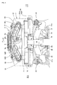
- FIG. 3 is a front view taken in the direction of arrows along line III-III in FIG. 2 with the vehicle body cover 10 and the steering handlebars 13 removed, and with the upper side case half body 70A of the air cleaner case 70 also removed.
- the left and right intake ducts 80L and 80R and an intake air temperature sensor 9 which will be described later, which are attached to the upper side case half body 70A, appear to be floating in the air in FIG. 3 .
- the lower side case half body 70B of the air cleaner case 70 extends downward between the left and right main reinforcing frames 21a, and reaches the position of the left and right main frames 21.
- the upper side case half body 70A is located above the left and right main reinforcing frames 21a, and is formed so as to be relatively wide.
- the lower side case half body 70B can be disposed in a small space between the frame members 21 and 21 a in the vicinity of the head pipe 20 forming the front portion of the vehicle body frame 2, and the frame members 21 and 21 a can protect the air cleaner 7.
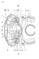
- FIG. 4 is a top view of the air cleaner case 70 and the fuel tank 6, the top view being taken in the direction of arrows along line IV-IV in FIG. 2 , with the vehicle body cover 10 removed.
- the air cleaner case 70 is formed with a generally rhombic shape, which is longer in the lateral (left-to-right) direction than in the longitudinal (front-to-back) direction.
- a plurality of intake ducts (here, a pair of left and right intake ducts 80L and 80R) are attached to the upper side case half body 70A. Of course, more than two intake ducts may be provided, as long as the left and right intake ducts form pairs.
- the filter element 71 provided on the partition member 72 which is interposed and fastened between the upper side case half body 70A and the lower side case half body 70B, has a plate-like shape, and is formed in a generally rectangular shape that is longer in the lateral direction than in the longitudinal direction of the vehicle (that is, its longer axis is parallel to the direction of width of the vehicle), so as to extend over substantially the entire area of the partition member 72.
- the left and right intake ducts 80L and 80R are attached to through holes 73 in the upper side case half body 70A at air cleaner case connecting portions 82 of the left and right intake ducts 80L and 80R, the left and right intake ducts 80L and 80R both having an intake port 81 which faces rearwardly.
- the left and right intake ducts 80L and 80R extend forwardly within the upper side case half body 70A, and bent portions 83 which are generally L-shaped lead to left and right discharge ports 84L and 84R, pointing towards the lateral centreline of the vehicle but in opposite directions from each other.
- left and right discharge ports 84L and 84R for discharging the outside air are disposed so as to be longitudinally offset from each other.
- the left discharge port 84L is located to the rear of the right discharge port 84R.
- the left and right intake ducts 80L and 80R introduce outside air into the upper side case half body 70A.
- the partition member 72 and the filter element 71 define a dirty side chamber 75, which is partitioned from the inside of the lower side case half body 70B.
- a clean side chamber 76 is defined within the lower side case half body 70B.
- the dirty side chamber 75 communicates with the clean side chamber 76 within the lower side case half body 70B via the filter element 71.
- the discharge ports 84L and 84R of the left and right intake ducts 80L and 80R are disposed so as to be longitudinally offset from each other within the dirty side chamber 75, a swirling air flow arises (counterclockwise as viewed from above in the present embodiment) within the dirty side chamber 75 during air intake.
- a swirling air flow arises (counterclockwise as viewed from above in the present embodiment) within the dirty side chamber 75 during air intake.
- an imbalance in usage range across the width of the dirty side chamber 75 can be prevented from occurring, and the filter element 71 can be made to function uniformly across its width. Because the inside of the dirty side chamber 75 can be used uniformly, intake performance can be maintained while keeping the air cleaner 7 compact.
- the intake ports 81 and 81 of the left and right intake ducts 80L and 80R are opened to the outside at a rear side portion of the air cleaner case 70, and the paths of the intake ducts 80L and 80R leading to the discharge ports 84L and 84R that discharge the intake air are disposed within the dirty side chamber 75 of the air cleaner case 70. Therefore, there are no projecting portions for the intake ducts 80L and 80R on the upper portion of the air cleaner case 70, and so the height of the air cleaner 7 is reduced, so that the air cleaner 7 can be formed in a compact manner. The height of a device covering the upper portion of the air cleaner case 70, and in particular the height of the vehicle body cover 10, can be reduced.
- the respective intake ports 81 of the left and right intake ducts 80L and 80R are located forwardly of a rear end portion 70a of the air cleaner case 70 which is formed with a generally rhombic shape in plan view, so that a gap between the intake ports 81 and the rearwardly adjacent fuel tank 6 is secured.
- the shape of the fuel tank 6 can be set relatively freely. Coupled with this, it is easy to form spaces around the intake ports 81 between the intake ports 81 and the fuel tank 6, so that intake is ensured even in longitudinally small spaces.
- the intake air introduced into the upper side case half body 70A needs to have a required flow velocity.
- lengths of the left and right intake ducts 80L and 80R need to be secured.
- the intake ports 81 cannot be positioned so as to extend a long way from the rear from the air cleaner case connecting portions 82.
- the necessary lengths of the left and right intake ducts 80L and 80R are secured by making the lengths from the air cleaner case connecting portions 82 to the left and right discharge ports 84L and 84R in the forward direction within the upper side case half body 70A longer than the lengths from the air cleaner case connecting portions 82 to the intake ports 81.
- the left and right intake ducts 80L and 80R are inclined upwardly from the air cleaner case connecting portions 82 to the respective left and right discharge ports 84L and 84R, and furthermore the discharge ports 84L and 84R are oriented downwardly.
- the discharge ports 84L and 84R are disposed in the vicinity of a ceiling 77 within the dirty side chamber 75.
- FIG. 5 is a top view of the lower side case half body 70B of the air cleaner case 70 and the fuel tank 6, the top view being taken in the direction of arrows along line V-V in FIG. 2 , with the vehicle body cover 10 removed, and with the upper side case half body 70A of the air cleaner case 70, the partition member 72, and the filter element 71 also removed.
- the left and right intake ducts 80L and 80R and an intake air temperature sensor 9 attached to the upper side case half body 70A are shown appearing to float in the air in FIG. 5 .
- a clean side chamber connecting portion 88 on the upstream side of the connecting tube 86 is attached to a through hole 79 of the lower side case half body 70B in a bottom portion 78 of the lower side case half body 70B.
- the funnel portion 87a forming the suction port 87 is open toward the filter element 71 within the lower side case half body 70B (see FIG. 1 and FIG. 2 ).
- the discharge ports 84L and 84R of the left and right intake ducts 80L and 80R partly overlap the suction port 87 of the connecting tube 86 in plan view.
- Such an arrangement of the left and right intake ducts 80L and 80R reduces the width of the air cleaner case 70 in which the left and right intake ducts 80L and 80R are placed.
- the intake air temperature sensor 9 is attached to an attachment opening 90 provided in an upper rear portion of the upper side case half body 70A of the air cleaner case 70.
- a detecting end 9a of the intake air temperature sensor 9 is inserted into the upper side case half body 70A, and extends obliquely forwardly and downwardly so as to be disposed in the vicinity of the discharge port 84L of the left intake duct 80L (see FIG. 3 ).
- the intake air temperature sensor 9 can detect the temperature of the intake air that has just been discharged from the discharge port 84L of the left intake duct 80L with little disturbance. Because the intake air temperature sensor 9 is attached in an empty space between the upper rear portion of the upper side case half body 70A and the upper portion of the fuel tank 6, the intake air temperature sensor 9 can be attached in a small space, and the maintenance of the intake air temperature sensor 9 is facilitated.
- engaging portions 89 for fixing the left and right intake ducts 80L and 80R, respectively, are formed within the dirty side chamber 75.
- FIG. 6 which shows the inner surface of the upper side case half body 70A, FIG. 6 being taken in the direction of arrows along line VI-VI in FIG. 2 , engagement receiving portions 74 are formed on the inner surface of the upper side case half body 70A, that is, the ceiling 77 of the dirty side chamber 75.
- the respective engaging portions 89 of the left and right intake ducts 80L and 80R are engaged with the engagement receiving portions 74 on the ceiling 77 of the dirty side chamber 75, whereby the left and right intake ducts 80L and 80R are fixed to the inside of the upper side case half body 70A.
- the air cleaner case connecting portions 82 and the engaging portions 89 allow the left and right intake ducts 80L and 80R to be positioned easily during assembly, and the vibration of the intake ducts 80L and 80R during air intake is suppressed, so that air can flow in the desired directions.
- the air cleaner 7 has an air cleaner case 70
- the air cleaner case 70 has a filter element 71 within it, and is partitioned into a dirty side chamber 75 and a clean side chamber 76
- a plurality of intake ducts 80L and 80R for leading outside air into the dirty side chamber 75 of the air cleaner case 70 are provided so as to form a left-right pair.
- the intake ducts 80L and 80R forming the left-right pair have intake ports 81 open to the outside at rear portions of the air cleaner case 70.
- the paths housed within the dirty side chamber 75 have bent portions 83.
- the discharge ports 84L and 84R of the intake ducts 80L and 80R forming the left-right pair are disposed so as to point towards a lateral centre of the air cleaner case 70, and are longitudinally offset from each other.
- the intake ports 81 of the plurality of intake ducts 80L and 80R forming the left-right pair are open to the outside at rear side portions of the air cleaner case 70, and the paths of the intake ducts 80L and 80R leading to the discharge ports 84L and 84R for discharging the intake air into the dirty side chamber 75 of the air cleaner case 70 are disposed within the dirty side chamber 75.
- projecting portions for the intake ducts 80L and 80R are not formed on the upper portion of the air cleaner case 70. Therefore, a reduction in height can be achieved.
- the intake ducts 80L and 80R forming the left-right pair have the bent portions 83 in the paths housed within the dirty side chamber 75, and the discharge ports 84L and 84R are disposed so as to point towards the lateral centreline of the air cleaner case 70 and are longitudinally offset from each other.
- a swirling air flow can be produced within the dirty side chamber 75 during intake, so that the inside of the dirty side chamber 75 can be used uniformly. It is therefore possible to secure an intake capacity and lengths of the intake ducts 80L and 80R, and maintain intake performance, while making the air cleaner 7 compact.
- the intake ducts 80L and 80R extend upwardly to the discharge ports 84L and 84R from the air cleaner case connecting portions 82 which are attached so as to penetrate the air cleaner case 70, and are inclined to approach a ceiling 77 of the dirty side chamber 75.
- the discharge ports 84L and 84R are oriented downwardly.
- the discharge ports 84L and 84R of the intake ducts 80L and 80R are disposed near the ceiling 77 within the dirty side chamber 75, the inside of the dirty side chamber 75 can be used uniformly. It is therefore possible to secure an intake capacity and lengths of the intake ducts 80L and 80R, and maintain intake performance, while making the air cleaner 7 compact.
- the motorcycle 1 has a fuel tank 6 mounted on an upper portion of the vehicle body frame 2.
- the air cleaner case 70 is disposed between a head pipe 20 of the vehicle body frame 2 and the fuel tank 6.
- the intake ports 81 of the intake ducts 80L and 80R open to the rear of the air cleaner case 70, and are disposed forwardly of a rear end portion 70a of the air cleaner case 70. It is thus possible to avoid interference between the fuel tank 6 (which is rearwardly adjacent to the air cleaner case 70) and the intake ports 81, and surely take in the air, with a space being formed between the fuel tank 8 and the intake ports 81.
- the air cleaner case 70 is divided into an upper side case half body 70A and a lower side case half body 70B.
- the filter element 71 is disposed between the upper side case half body 70A and the lower side case half body 70B.
- the dirty side chamber 75 is defined within the upper side case half body 70A.
- the clean side chamber 76 is defined within the lower side case half body 70B.
- the upper side case half body 70A of the air cleaner case 70 is formed so as to be larger in its lateral direction than its longitudinal direction.
- the filter element 71 has a plate shape, and is disposed such that its longer axis is parallel to the direction of width of the vehicle (the lateral direction).
- the air cleaner case 70 is divided into the upper part and the lower part and is shaped so as to be larger in the lateral direction, the air cleaner 7 becomes compact in the longitudinal direction of the vehicle.
- the filter element 71 has a plate shape, capacity can be secured while keeping the air cleaner 7 compact in a height direction.
- a connecting tube 86 for leading intake air into the internal combustion engine 3 is connected to the clean side chamber 76 of the air cleaner case 70, and the discharge ports 84L and 84R of the intake ducts 80L and 80R at least partly overlap a suction port 87 of the connecting tube 86 in plan view.
- the intake ducts 80L and 80R are formed such that the lengths of the intake ducts 80L and 80R from the air cleaner case connecting portions 82 to the discharge ports 84L and 84R are longer than the lengths of the intake ducts 80L and 80R from the air cleaner case connecting portions 82 to the intake ports 81.
- the intake ducts 80L and 80R within the air cleaner case 70 are formed so as to be long, and the intake ducts 80L and 80R outside the air cleaner case 70 are formed so as to be short, interference with parts around the air cleaner case 70 is avoided, and tube lengths of the intake ducts 80L and 80R can be secured. Thus, intake performance can be maintained while keeping the air cleaner device compact.
- engaging portions 89 are formed on the parts of the intake ducts 80L and 80R which are housed in the dirty side chamber 75.
- Engagement receiving portions 74 are formed on a ceiling 77 of the dirty side chamber 75. The engaging portions 89 are engaged with the engagement receiving portions 74, so that the intake ducts 80L and 80R are fixed.
- the intake ducts 80L and 80R are engaged with and fixed to the ceiling 77 of the dirty side chamber 75, the intake ducts 80L and 80R can be positioned easily during assembly, and vibration of the intake ducts 80L and 80R during suction of intake air is suppressed, so that an air flow can be led in targeted directions.
- An attachment opening 90 for attaching an intake air temperature sensor 9 is formed in an upper rear portion of the upper side case half body 70A of the air cleaner case 70, and the intake air temperature sensor 9 is disposed in a vicinity of the discharge port 84L of the intake duct 80L.
- the intake air temperature sensor 9 can measure the temperature of the intake air that has just been discharged from the discharge port 84L.
- the attachment opening 90 is provided in the upper rear portion of the air cleaner case 70, the intake air temperature sensor 9 can be attached in a gap between the air cleaner case 70 and the fuel tank 6 to the rear.
- the discharge port 84R of the right intake duct 80R may be disposed in the vicinity of the intake air temperature sensor 9.
- FIG. 7 and FIG. 8 An air cleaner device for a vehicle according to a second embodiment of the present invention will now be described with reference to FIG. 7 and FIG. 8 .
- the orientations and positions of attachment of intake ducts 80L and 80R in an air cleaner case 70 are different from those in the first embodiment. Otherwise, the configuration of the second embodiment is similar to that of the first embodiment.
- the functions, actions, and effects of the second embodiment are also similar to those of the first embodiment.
- corresponding members, devices, and the like are identified by the same reference numerals as in the first embodiment in the Figures, the specification, and claims. Differences from the first embodiment in the attachment orientations and positions and resulting differences in actions and effects will be mainly described with reference to FIG. 7 and FIG. 8 . Description of other common constitutions and other actions and effects will be omitted.
- a fuel tank 6 is mounted on an upper portion of a vehicle body frame 2 of a motorcycle 1 as shown in FIG. 1 , and an air cleaner case 70 is disposed between a head pipe 20 of the vehicle body frame 2 and the fuel tank 6.
- intake ports 81 of a left and a right intake duct 80L and 80R are disposed so as to open to the front of the air cleaner case 70.
- FIG. 8 is a top view of a lower side case half body 70B of the air cleaner case 70 and the fuel tank 6, the top view being taken in the direction of arrows along line VIII-VIII in FIG. 7 , with a vehicle body cover 10 removed, and with an upper side case half body 70A of the air cleaner case 70, a partition member 72, and a filter element 71 removed.
- the arrangement of the intake ducts 80L and 80R within the air cleaner case 70 is similar to that in the first embodiment except that the front and the rear are reversed.
- the intake ports 81 of the left and right intake ducts 80L and 80R are disposed so as to open to the front of the air cleaner case 70, unlike the first embodiment.
- the intake ports 81 can be disposed using a space in front of the air cleaner case 70 when a sufficient space cannot be secured at the rear of the air cleaner case 70 in the layout of the parts of the motorcycle 1.
- the positions of the engaging portions 89 of the intake ducts 81L and 80R of the second embodiment in FIG. 8 are different from those of the engaging portions 89 of the first embodiment in FIG. 5 .
- engagement receiving portions (74) in the second embodiment are similarly provided at positions different from those of the engagement receiving portions 74 of the first embodiment shown in FIG. 6 , so as to correspond to the positions of the engaging portions 89 of the second embodiment.
- the discharge port 84R of the right intake duct 80R is disposed in the vicinity of the intake air temperature sensor 9 in FIG. 8
- the discharge port 84L of the left intake duct 80L may be disposed in the vicinity of the intake air temperature sensor 9 in FIG. 8 .
- the arrangement of the left and the right of the air cleaner device according to the embodiments is an example.
- the present invention can also be applied to an arrangement in which the left and the right are reversed.
- the arrangement of the air cleaner device of the present invention can be either the arrangement in which the intake ports of the intake ducts open rearwardly (similar to the first embodiment), or the arrangement in which the intake ports of the intake ducts open forwardly (similar to the second embodiment).
Abstract
Description
- The present invention relates to an air cleaner device for a vehicle having an internal combustion engine, where the air cleaner device is mounted on a vehicle body frame.
- Japanese Patent No.
4128639 - In Japanese Patent No.
4128639 - In view of the above-described conventional technology, it is an object of at least the preferred embodiments of the present invention to provide an air cleaner device that is formed in a compact manner while securing an intake capacity, and which can improve intake performance, in a vehicle having an internal combustion engine and the air cleaner device mounted on a vehicle body frame.
- According to a first aspect of the present invention, there is provided an air cleaner device for a vehicle, the vehicle having an internal combustion engine and the air cleaner device being mounted on a vehicle body frame, the air cleaner device comprising: an air cleaner case having a filter element therein, and being partitioned into a dirty side chamber and a clean side chamber; and a plurality of intake ducts for leading outside air into the dirty side chamber of the air cleaner case, the intake ducts being provided so as to form a left-right pair, wherein the intake ducts forming the left-right pair have intake ports open to the outside of the air cleaner case, the parts of the intake ducts which are housed within the dirty side chamber and which lead to discharge ports having bent portions, and the discharge ports of the intake ducts forming the left-right pair are disposed so as to be oriented toward a lateral centre of the air cleaner case and are longitudinally offset from each other.
- With this arrangement, as the intake ports are open to the outside of the air cleaner case, and the paths of the intake ducts leading to the discharge ports for discharging intake air into the dirty side chamber of the air cleaner case are disposed within the dirty side chamber, projecting portions for the intake ducts are not formed on the upper portion of the air cleaner case, and so a reduction in height can be achieved.
- Further, the intake ducts have bent portions housed within the dirty side chamber, and the discharge ports are disposed so as to point towards the centre of the air cleaner case and are longitudinally offset from each other. Thus, a swirling air flow can be produced within the dirty side chamber during intake, so that the inside of the dirty side chamber can be used uniformly. It is therefore possible to secure an intake capacity and lengths of the intake ducts, and maintain intake performance, while making the air cleaner device compact.
- Preferably, the intake ducts extend upwardly to the discharge ports from air cleaner case connecting portions attached so as to penetrate the air cleaner case, and are inclined to approach a ceiling of the dirty side chamber, and the discharge ports are oriented downwardly.
- Because the discharge ports of the intake ducts are disposed in the vicinity of the ceiling within the dirty side chamber, the inside of the dirty side chamber can be used uniformly. It is therefore possible to secure an intake capacity and lengths of the intake ducts, and maintain intake performance, while making the air cleaner device compact.
- Preferably, a fuel tank is mounted on an upper portion of the vehicle body frame of the vehicle, and the air cleaner case is disposed between a head pipe of the vehicle body frame and the fuel tank, and the intake ports of the intake ducts are open to the rear of the air cleaner case, and are disposed forwardly of a rear end portion of the air cleaner case.
- With this arrangement, it is possible to avoid interference between the fuel tank rearwardly adjacent to the air cleaner case and the intake ports, and surely take in the air, as a space is formed between the fuel tank and the intake ports.
- In an alternative preferred form, a fuel tank is mounted on an upper portion of the vehicle body frame of the vehicle, and the air cleaner case is disposed between a head pipe of the vehicle body frame and the fuel tank, and the intake ports of the intake ducts are disposed so as to open to the front of the air cleaner case.
- With this arrangement, a space in front of the air cleaner case can be used when sufficient space cannot be secured to the rear of the air cleaner case because of the layout of the parts of the vehicle.
- Preferably, the air cleaner case is divided into an upper side case half body and a lower side case half body, the filter element is disposed between the upper side case half body and the lower side case half body, the dirty side chamber is defined within the upper side case half body, and the clean side chamber is defined within the lower side case half body, the upper side case half body of the air cleaner case is formed so as to be larger in a lateral direction of the vehicle than a longitudinal direction of the vehicle, and the filter element has a plate shape, and is disposed such its longer axis is parallel to the lateral direction of the vehicle.
- With this arrangement, the air cleaner device can be kept longitudinally compact. In addition, because the filter element is plate-shaped, capacity can be secured while the air cleaner device is made vertically compact.
- Preferably, a connecting tube for leading intake air into the internal combustion engine is connected to the clean side chamber of the air cleaner case, and the discharge ports of the intake ducts at least partly overlap a suction port of the connecting tube in plan view.
- Thus, because the positions of the discharge ports of the intake ducts are brought close to the connecting tube in the lateral direction, the lateral size of the air cleaner case can be reduced.
- Preferably, the intake ducts are formed such that the lengths of the intake ducts between air cleaner case connecting portions attached so as to penetrate the air cleaner case and the discharge ports are longer than the lengths of the intake ducts between the air cleaner case connecting portions and the intake ports.
- With this arrangement, because the intake ducts within the air cleaner case are long, and the intake ducts outside the air cleaner case are short, interference with parts around the air cleaner case is avoided, and tube lengths of the intake ducts can be secured. Thus, intake performance can be maintained while the air cleaner device is kept compact.
- Preferably, engaging portions are formed on parts of the intake ducts housed in the dirty side chamber, engagement receiving portions are formed on a ceiling of the dirty side chamber, and the engaging portions are engaged with the engagement receiving portions, whereby the intake ducts are fixed.
- Thus, the intake ducts are engaged with and fixed to the ceiling of the dirty side chamber, and so the intake ducts are easily positioned during assembly. Further, the vibration of the intake ducts during suction of the intake air is suppressed, so that an air flow can be led in targeted directions.
- In a preferred form, an attachment opening for attaching an intake air temperature sensor is formed in an upper rear portion of the upper side case half body of the air cleaner case, and the intake air temperature sensor is disposed in a vicinity of either one of the discharge ports of the intake ducts forming the left-right pair.
- Thus, the intake air temperature sensor can measure the temperature of the intake air that has just been discharged from the discharge port. In addition, because the attachment opening is provided in the upper rear portion of the air cleaner case, the intake air temperature sensor can be attached in a gap between the air cleaner case and the fuel tank.
- Preferred embodiments of the invention will now be described by way of example only and with reference to the accompanying drawings, in which:
-
FIG. 1 is a right side view of a motorcycle mounted with an air cleaner device according to a first embodiment of the present invention; -
FIG. 2 is a right side view of the air cleaner and vicinities thereof in the motorcycle ofFIG. 1 in a state in which a vehicle body cover is removed; -
FIG. 3 is a front view taken in the direction of arrows along line III-III inFIG. 2 with the vehicle body cover and steering handlebars removed, and with the upper side case half body of an air cleaner case further removed; -
FIG. 4 is a top view of the air cleaner case and a fuel tank, the top view being taken in the direction of arrows along line IV-IV inFIG. 2 , with the vehicle body cover removed; -
FIG. 5 is a top view of the lower side case half body of the air cleaner case and the fuel tank, the top view being taken in the direction of arrows along line V-V inFIG. 2 , with the vehicle body cover removed, and with the upper side case half body of the air cleaner case, a partition member, and a filter element removed; -
FIG. 6 is a bottom view of the inner surface of the upper side case half body, the bottom view being taken in the direction of arrows along line VI-VI inFIG. 2 ; -
FIG. 7 is a right side view of an air cleaner device according to a second embodiment of the present invention and vicinities thereof in a motorcycle mounted with the air cleaner device in a state in which a vehicle body cover is removed, as inFIG. 2 ; and -
FIG. 8 is a top view of the lower side case half body of an air cleaner case and a fuel tank in the second embodiment, the top view being taken in the direction of arrows along line VIII-VIII inFIG. 7 , with the vehicle body cover removed, and with the upper side case half body of the air cleaner case, a partition member, and a filter element removed, as inFIG. 5 . - An air cleaner device for a vehicle according to a first embodiment of the present invention will hereinafter be described with reference to
FIGS. 1 to 6 . - The vehicle in the present embodiment is a saddle riding type vehicle having an internal combustion engine and the air cleaner device mounted on a vehicle body frame, and is specifically a motorcycle. Terms such as forward, rearward, left, right, up, down and the like in the claims and the description of the present specification should be interpreted with reference to a rider who rides on the vehicle.
- In the Figures, arrow FR indicates the forward direction of the vehicle, arrow LH indicates the left direction of the vehicle, arrow RH indicates the right direction of the vehicle, and arrow UP indicates the upward direction of the vehicle.
-
FIG. 1 is a right side view of a motorcycle 1 according to a first embodiment of the present invention. As shown inFIG. 1 , thevehicle body frame 2 of the motorcycle 1 is covered by a vehicle body cover (cowl) 10 made of a synthetic resin. - The
vehicle body frame 2 of the motorcycle 1 includes: ahead pipe 20 provided at a front end portion of the vehicle; a pair of left and rightmain frames 21 branching to left and right from a lower portion of thehead pipe 20 and extending rearward while slanting rearwardly downwards; and mainreinforcing frames 21 a obliquely connecting an upper portion of thehead pipe 20 to the left and rightmain frames 21. - The
head pipe 20 steerably supports afront fork 12, which in turn supports afront wheel 11.Steering handlebars 13 are coupled to an upper portion of thefront fork 12. - Left and
right centre frames 22 extend downwardly from the rear ends of the left and rightmain frames 21, and bend rearwardly. - Left and right down
frames 23 extend rearwardly and steeply downwardly from portions of the left and rightmain frames 21 in the vicinity of thehead pipe 20. Lower end portions of thedown frames 23 are connected to down reinforcingframes 23a which extend forwardly and downwardly from longitudinally middle portions of the left and rightmain frames 21. - Rear frames (not shown in the Figures) which extend rearwardly from the
centre frames 22 are provided to support aseat 14 for occupants. - Incidentally, the left and right
main frames 21, thecentre frames 22, and the rear frames are coupled to each other by cross members (not shown in the Figures) to ensure rigidity of thevehicle body frame 2. - The
seat 14 for occupants is configured as a tandem type seat obtained by integrally forming a seat for a driver and a seat for a passenger. Afuel tank 6 is mounted in front of theseat 14 for occupants and on upper portions of the pair of left and rightmain frames 21, in such a manner as to be covered by thevehicle body cover 10. Thevehicle body cover 10 has an opening to expose a refuellingportion 6a provided on an upper surface of thefuel tank 6. - The
centre frames 22 are provided with apivot plate 22a. Thepivot plate 22a rotatably supports a front end of arear fork 16 via apivot bolt 15. Arear wheel 17 is rotatably supported on a rear end of therear fork 16. Therear fork 16 is vertically swingably supported via a rear cushion (not shown in the Figures). - An internal combustion engine 3 of the motorcycle 1 is suspended on the
vehicle body frame 2 at lower end portions of thedown frames 23, connecting portions between themain frames 21 and the down reinforcingframes 23a, and upper portions of thecentre frames 22. - The internal combustion engine 3 forms a so-called power unit, which integrally includes a transmission 5 within a crankcase 4. A
crankshaft 41 and a transmission shaft are housed in the crankcase 4. The internal combustion engine 3 is mounted in the motorcycle 1 with thecrankshaft 41 oriented in a lateral (left-right) direction of the vehicle. - The power of the internal combustion engine 3 is transmitted from an
output shaft 42 projecting from the left of the crankcase 4 to therear wheel 17 via achain drive mechanism 43. - In this embodiment, the internal combustion engine 3 is an in-line two-cylinder water-cooled four-stroke-cycle engine, having a
cylinder portion 30 extending upwardly from an upper front portion of the crankcase 4 and inclined forwardly. Thecylinder portion 30 includes: acylinder block 31 coupled to the upper front portion of the crankcase 4; acylinder head 32 coupled to an upper portion of thecylinder block 31; and acylinder head cover 33 covering an upper portion of thecylinder head 32. - A
throttle body 34 and an air cleaner (the "air cleaner device" in the present invention) 7 forming an intake system are connected in that order to a rear surface of thecylinder portion 30 of the internal combustion engine 3. - Specifically, respective intake ports extending from the two cylinders of the
cylinder block 31 to the rear surface of thecylinder head 32 are integrated into one intake port by anintake manifold portion 35 provided with a fuel injection valve (not shown in the Figures) for each cylinder, and the intake port is connected to thesingle throttle body 34. - The
throttle body 34 is attached to theintake manifold portion 35. An upper end (upstream end) of thethrottle body 34 is connected to theair cleaner 7 via a connectingtube 86 to be described later. - In addition, an
exhaust pipe 36 and amuffler 37 forming an exhaust system are connected in that order to a front surface of thecylinder portion 30. - Specifically, the
exhaust pipe 36 is connected to outlets of respective exhaust ports extending from the two cylinders to the front surface of thecylinder head 32. Theexhaust pipe 36 extends downwardly, bends to the rear, extends rearwardly, and is connected to themuffler 37 disposed at a rear portion of the vehicle. Incidentally, acatalyst 36a is housed in a part of theexhaust pipe 36 located in front of the engine. - The
air cleaner 7 includes: an aircleaner case 70 formed from an upper side casehalf body 70A and a lower side casehalf body 70B; apartition member 72 disposed so as to be interposed between the upper side casehalf body 70A and the lower side casehalf body 70B, and provided with afilter element 71; and a pair of left andright intake ducts air cleaner case 70. - In addition, the lower side case
half body 70B is provided with a connectingtube 86 connected to thethrottle body 34 on the side of the internal combustion engine 3. - As shown in
FIG. 1 , theair cleaner case 70 is disposed between thehead pipe 20 and thefuel tank 6 mounted on the main frames 21. Theair cleaner case 70 is mounted on thevehicle body frame 2 in a state of being interposed between the left and rightmain frames 21 and the left and right main reinforcingframes 21 a. - The connecting
tube 86 extends upstream from a lower end thereof connected to thethrottle body 34, and is attached to the lower side casehalf body 70B so as to penetrate the lower side casehalf body 70B. Afunnel portion 87a, which increases in diameter toward thefilter element 71, is formed at asuction port 87 within the lower side casehalf body 70B. -
FIG. 2 shows theair cleaner 7 and the surrounding area of motorcycle 1 in a state in which the vehicle body cover 10 inFIG. 1 is removed. - The lower side case
half body 70B of theair cleaner 7 has a lower portion which has a relatively small width (lateral dimension), as shown inFIG. 3 . The lower side casehalf body 70B is disposed between the left and right main reinforcingframes 21 a in the vicinity of thehead pipe 20, and is attached toattachment brackets 24 of the main reinforcingframes 21 a. - An upper portion of the lower side case
half body 70B has a relatively large width as compared with the lower portion of the lower side casehalf body 70B. The upper side casehalf body 70A, which similarly has a relatively large width, is fastened above the lower side casehalf body 70B, with thepartition member 72 interposed between the upper side casehalf body 70A and the lower side casehalf body 70B. The upper side casehalf body 70A is disposed so as to be located above the left and right main reinforcingframes 21 a and the left and right main frames 21. -
FIG. 3 is a front view taken in the direction of arrows along line III-III inFIG. 2 with thevehicle body cover 10 and thesteering handlebars 13 removed, and with the upper side casehalf body 70A of theair cleaner case 70 also removed. - Hence, the left and
right intake ducts half body 70A, appear to be floating in the air inFIG. 3 . - As shown in
FIG. 3 , the lower side casehalf body 70B of theair cleaner case 70 extends downward between the left and right main reinforcingframes 21a, and reaches the position of the left and right main frames 21. - In addition, the upper side case
half body 70A is located above the left and right main reinforcingframes 21a, and is formed so as to be relatively wide. - Hence, a sufficient capacity for the
air cleaner 7 can be ensured, even though the space in the longitudinal (front-to-back) direction for theair cleaner 7 is limited as theair cleaner 7 is interposed between thehead pipe 20 and thefuel tank 6. - That is, while the capacities of the upper side case
half body 70A and the lower side casehalf body 70B can be secured, the lower side casehalf body 70B can be disposed in a small space between theframe members head pipe 20 forming the front portion of thevehicle body frame 2, and theframe members air cleaner 7. -
FIG. 4 is a top view of theair cleaner case 70 and thefuel tank 6, the top view being taken in the direction of arrows along line IV-IV inFIG. 2 , with the vehicle body cover 10 removed. As shown inFIG. 4 , theair cleaner case 70 is formed with a generally rhombic shape, which is longer in the lateral (left-to-right) direction than in the longitudinal (front-to-back) direction. A plurality of intake ducts (here, a pair of left andright intake ducts half body 70A. Of course, more than two intake ducts may be provided, as long as the left and right intake ducts form pairs. - The
filter element 71 provided on thepartition member 72, which is interposed and fastened between the upper side casehalf body 70A and the lower side casehalf body 70B, has a plate-like shape, and is formed in a generally rectangular shape that is longer in the lateral direction than in the longitudinal direction of the vehicle (that is, its longer axis is parallel to the direction of width of the vehicle), so as to extend over substantially the entire area of thepartition member 72. - The left and
right intake ducts holes 73 in the upper side casehalf body 70A at air cleanercase connecting portions 82 of the left andright intake ducts right intake ducts intake port 81 which faces rearwardly. The left andright intake ducts half body 70A, andbent portions 83 which are generally L-shaped lead to left andright discharge ports - In addition, the left and
right discharge ports left discharge port 84L is located to the rear of theright discharge port 84R. - The left and
right intake ducts half body 70A. Thepartition member 72 and thefilter element 71 define adirty side chamber 75, which is partitioned from the inside of the lower side casehalf body 70B. Aclean side chamber 76 is defined within the lower side casehalf body 70B. - The
dirty side chamber 75 communicates with theclean side chamber 76 within the lower side casehalf body 70B via thefilter element 71. - Because the
discharge ports right intake ducts dirty side chamber 75, a swirling air flow arises (counterclockwise as viewed from above in the present embodiment) within thedirty side chamber 75 during air intake. Thus, an imbalance in usage range across the width of thedirty side chamber 75 can be prevented from occurring, and thefilter element 71 can be made to function uniformly across its width. Because the inside of thedirty side chamber 75 can be used uniformly, intake performance can be maintained while keeping theair cleaner 7 compact. - In addition, the
intake ports right intake ducts air cleaner case 70, and the paths of theintake ducts discharge ports dirty side chamber 75 of theair cleaner case 70. Therefore, there are no projecting portions for theintake ducts air cleaner case 70, and so the height of theair cleaner 7 is reduced, so that theair cleaner 7 can be formed in a compact manner. The height of a device covering the upper portion of theair cleaner case 70, and in particular the height of thevehicle body cover 10, can be reduced. - Incidentally, the
respective intake ports 81 of the left andright intake ducts rear end portion 70a of theair cleaner case 70 which is formed with a generally rhombic shape in plan view, so that a gap between theintake ports 81 and the rearwardlyadjacent fuel tank 6 is secured. - In addition, the shape of the
fuel tank 6 can be set relatively freely. Coupled with this, it is easy to form spaces around theintake ports 81 between theintake ports 81 and thefuel tank 6, so that intake is ensured even in longitudinally small spaces. - In addition, for effective use of the space within the
dirty side chamber 75 by a sufficient swirling air flow, the intake air introduced into the upper side casehalf body 70A needs to have a required flow velocity. In order to obtain the flow velocity of the incoming outside air, lengths of the left andright intake ducts - In order to avoid interference with the
fuel tank 6, theintake ports 81 cannot be positioned so as to extend a long way from the rear from the air cleanercase connecting portions 82. Thus, in the present embodiment, the necessary lengths of the left andright intake ducts case connecting portions 82 to the left andright discharge ports half body 70A longer than the lengths from the air cleanercase connecting portions 82 to theintake ports 81. - In addition, as shown in
FIG. 3 (and alsoFIG. 2 ), the left andright intake ducts case connecting portions 82 to the respective left andright discharge ports discharge ports discharge ports ceiling 77 within thedirty side chamber 75. Thus, a vertical imbalance in usage range within thedirty side chamber 75 can be prevented from occurring. Because the inside of thedirty side chamber 75 can be used uniformly, intake performance can be maintained while keeping theair cleaner 7 compact. -
FIG. 5 is a top view of the lower side casehalf body 70B of theair cleaner case 70 and thefuel tank 6, the top view being taken in the direction of arrows along line V-V inFIG. 2 , with the vehicle body cover 10 removed, and with the upper side casehalf body 70A of theair cleaner case 70, thepartition member 72, and thefilter element 71 also removed. The left andright intake ducts air temperature sensor 9 attached to the upper side casehalf body 70A are shown appearing to float in the air inFIG. 5 . - As shown in
FIG. 5 , a clean sidechamber connecting portion 88 on the upstream side of the connectingtube 86 is attached to a throughhole 79 of the lower side casehalf body 70B in abottom portion 78 of the lower side casehalf body 70B. Thefunnel portion 87a forming thesuction port 87 is open toward thefilter element 71 within the lower side casehalf body 70B (seeFIG. 1 andFIG. 2 ). - In addition, as shown in
FIG. 5 , thedischarge ports right intake ducts suction port 87 of the connectingtube 86 in plan view. Such an arrangement of the left andright intake ducts air cleaner case 70 in which the left andright intake ducts - Incidentally, in the present embodiment, the intake
air temperature sensor 9 is attached to anattachment opening 90 provided in an upper rear portion of the upper side casehalf body 70A of theair cleaner case 70. A detectingend 9a of the intakeair temperature sensor 9 is inserted into the upper side casehalf body 70A, and extends obliquely forwardly and downwardly so as to be disposed in the vicinity of thedischarge port 84L of theleft intake duct 80L (seeFIG. 3 ). - Therefore, the intake
air temperature sensor 9 can detect the temperature of the intake air that has just been discharged from thedischarge port 84L of theleft intake duct 80L with little disturbance. Because the intakeair temperature sensor 9 is attached in an empty space between the upper rear portion of the upper side casehalf body 70A and the upper portion of thefuel tank 6, the intakeair temperature sensor 9 can be attached in a small space, and the maintenance of the intakeair temperature sensor 9 is facilitated. - In addition, as shown in
FIG. 5 , engagingportions 89 for fixing the left andright intake ducts dirty side chamber 75. - On the other hand, as shown in
FIG. 6 , which shows the inner surface of the upper side casehalf body 70A,FIG. 6 being taken in the direction of arrows along line VI-VI inFIG. 2 ,engagement receiving portions 74 are formed on the inner surface of the upper side casehalf body 70A, that is, theceiling 77 of thedirty side chamber 75. - That is, the respective engaging
portions 89 of the left andright intake ducts engagement receiving portions 74 on theceiling 77 of thedirty side chamber 75, whereby the left andright intake ducts half body 70A. - Hence, the air cleaner
case connecting portions 82 and the engagingportions 89 allow the left andright intake ducts intake ducts - Features of the air cleaner device for a vehicle according to the present embodiment described above will be described again in the following summary.
- In a motorcycle 1 having an internal combustion engine 3 and an
air cleaner 7 mounted on avehicle body frame 2, theair cleaner 7 has an aircleaner case 70, theair cleaner case 70 has afilter element 71 within it, and is partitioned into adirty side chamber 75 and aclean side chamber 76, and a plurality ofintake ducts dirty side chamber 75 of theair cleaner case 70 are provided so as to form a left-right pair. Theintake ducts intake ports 81 open to the outside at rear portions of theair cleaner case 70. Of the paths of theintake ducts ports dirty side chamber 75, the paths housed within thedirty side chamber 75 have bentportions 83. Thedischarge ports intake ducts air cleaner case 70, and are longitudinally offset from each other. - Hence, the
intake ports 81 of the plurality ofintake ducts air cleaner case 70, and the paths of theintake ducts discharge ports dirty side chamber 75 of theair cleaner case 70 are disposed within thedirty side chamber 75. Thus, projecting portions for theintake ducts air cleaner case 70. Therefore, a reduction in height can be achieved. - The
intake ducts bent portions 83 in the paths housed within thedirty side chamber 75, and thedischarge ports air cleaner case 70 and are longitudinally offset from each other. Thus, a swirling air flow can be produced within thedirty side chamber 75 during intake, so that the inside of thedirty side chamber 75 can be used uniformly. It is therefore possible to secure an intake capacity and lengths of theintake ducts air cleaner 7 compact. - In addition, the
intake ducts discharge ports case connecting portions 82 which are attached so as to penetrate theair cleaner case 70, and are inclined to approach aceiling 77 of thedirty side chamber 75. Thedischarge ports - Hence, because the
discharge ports intake ducts ceiling 77 within thedirty side chamber 75, the inside of thedirty side chamber 75 can be used uniformly. It is therefore possible to secure an intake capacity and lengths of theintake ducts air cleaner 7 compact. - In addition, the motorcycle 1 has a
fuel tank 6 mounted on an upper portion of thevehicle body frame 2. Theair cleaner case 70 is disposed between ahead pipe 20 of thevehicle body frame 2 and thefuel tank 6. Theintake ports 81 of theintake ducts air cleaner case 70, and are disposed forwardly of arear end portion 70a of theair cleaner case 70. It is thus possible to avoid interference between the fuel tank 6 (which is rearwardly adjacent to the air cleaner case 70) and theintake ports 81, and surely take in the air, with a space being formed between the fuel tank 8 and theintake ports 81. - In addition, the
air cleaner case 70 is divided into an upper side casehalf body 70A and a lower side casehalf body 70B. Thefilter element 71 is disposed between the upper side casehalf body 70A and the lower side casehalf body 70B. Thedirty side chamber 75 is defined within the upper side casehalf body 70A. Theclean side chamber 76 is defined within the lower side casehalf body 70B. The upper side casehalf body 70A of theair cleaner case 70 is formed so as to be larger in its lateral direction than its longitudinal direction. Thefilter element 71 has a plate shape, and is disposed such that its longer axis is parallel to the direction of width of the vehicle (the lateral direction). - Therefore, because the
air cleaner case 70 is divided into the upper part and the lower part and is shaped so as to be larger in the lateral direction, theair cleaner 7 becomes compact in the longitudinal direction of the vehicle. In addition, because thefilter element 71 has a plate shape, capacity can be secured while keeping theair cleaner 7 compact in a height direction. - In addition, a connecting
tube 86 for leading intake air into the internal combustion engine 3 is connected to theclean side chamber 76 of theair cleaner case 70, and thedischarge ports intake ducts suction port 87 of the connectingtube 86 in plan view. - Therefore, because the positions of the
discharge ports intake ducts air cleaner case 70 can be reduced. - In addition, the
intake ducts intake ducts case connecting portions 82 to thedischarge ports intake ducts case connecting portions 82 to theintake ports 81. - Therefore, because the
intake ducts air cleaner case 70 are formed so as to be long, and theintake ducts air cleaner case 70 are formed so as to be short, interference with parts around theair cleaner case 70 is avoided, and tube lengths of theintake ducts - In addition, engaging
portions 89 are formed on the parts of theintake ducts dirty side chamber 75.Engagement receiving portions 74 are formed on aceiling 77 of thedirty side chamber 75. The engagingportions 89 are engaged with theengagement receiving portions 74, so that theintake ducts - Therefore, because the
intake ducts ceiling 77 of thedirty side chamber 75, theintake ducts intake ducts - An attachment opening 90 for attaching an intake
air temperature sensor 9 is formed in an upper rear portion of the upper side casehalf body 70A of theair cleaner case 70, and the intakeair temperature sensor 9 is disposed in a vicinity of thedischarge port 84L of theintake duct 80L. Thus, the intakeair temperature sensor 9 can measure the temperature of the intake air that has just been discharged from thedischarge port 84L. In addition, because the attachment opening 90 is provided in the upper rear portion of theair cleaner case 70, the intakeair temperature sensor 9 can be attached in a gap between theair cleaner case 70 and thefuel tank 6 to the rear. - Incidentally, the
discharge port 84R of theright intake duct 80R may be disposed in the vicinity of the intakeair temperature sensor 9. - An air cleaner device for a vehicle according to a second embodiment of the present invention will now be described with reference to
FIG. 7 andFIG. 8 . - Directions such as forward, rearward, left, right, up, down, and the like in the claims and the description of the present specification and the directions of arrows in the Figures are the same as in the first embodiment.
- In the second embodiment, the orientations and positions of attachment of
intake ducts cleaner case 70 are different from those in the first embodiment. Otherwise, the configuration of the second embodiment is similar to that of the first embodiment. The functions, actions, and effects of the second embodiment are also similar to those of the first embodiment. Thus, corresponding members, devices, and the like are identified by the same reference numerals as in the first embodiment in the Figures, the specification, and claims. Differences from the first embodiment in the attachment orientations and positions and resulting differences in actions and effects will be mainly described with reference toFIG. 7 andFIG. 8 . Description of other common constitutions and other actions and effects will be omitted. - As shown in
FIG. 7 , in the second embodiment (as in the first embodiment), afuel tank 6 is mounted on an upper portion of avehicle body frame 2 of a motorcycle 1 as shown inFIG. 1 , and an aircleaner case 70 is disposed between ahead pipe 20 of thevehicle body frame 2 and thefuel tank 6. However,intake ports 81 of a left and aright intake duct air cleaner case 70. -
FIG. 8 is a top view of a lower side casehalf body 70B of theair cleaner case 70 and thefuel tank 6, the top view being taken in the direction of arrows along line VIII-VIII inFIG. 7 , with a vehicle body cover 10 removed, and with an upper side casehalf body 70A of theair cleaner case 70, apartition member 72, and afilter element 71 removed. - As shown in
FIG. 8 , the arrangement of theintake ducts air cleaner case 70 is similar to that in the first embodiment except that the front and the rear are reversed. - The
intake ports 81 of the left andright intake ducts air cleaner case 70, unlike the first embodiment. - Therefore, the
intake ports 81 can be disposed using a space in front of theair cleaner case 70 when a sufficient space cannot be secured at the rear of theair cleaner case 70 in the layout of the parts of the motorcycle 1. - Incidentally, the positions of the engaging
portions 89 of theintake ducts 81L and 80R of the second embodiment inFIG. 8 are different from those of the engagingportions 89 of the first embodiment inFIG. 5 . Hence, though not shown in the Figures, engagement receiving portions (74) in the second embodiment are similarly provided at positions different from those of theengagement receiving portions 74 of the first embodiment shown inFIG. 6 , so as to correspond to the positions of the engagingportions 89 of the second embodiment. - In addition, while the
discharge port 84R of theright intake duct 80R is disposed in the vicinity of the intakeair temperature sensor 9 inFIG. 8 , thedischarge port 84L of theleft intake duct 80L may be disposed in the vicinity of the intakeair temperature sensor 9 inFIG. 8 . - The above-described embodiments only represent exemplary modes of the present invention, and can be subject to arbitrary modifications and applications without departing from the scope of the present invention. For example, in the foregoing embodiments, description has been made of a case where the present invention is applied to a motorcycle shown in
FIG. 1 . However, the invention is not limited to this, and the present invention may be applied to other vehicles (for example, other saddle riding type vehicles and the like), as long as the vehicles have a constitution corresponding to the constitution of claim 1. Incidentally, "saddle riding type vehicles" includes vehicles in general that are ridden while the vehicle bodies of the vehicles are straddled, and include not only motorcycles but also three-wheeled vehicles and four-wheeled vehicles such as buggies, ATVs and the like. - In addition, the arrangement of the left and the right of the air cleaner device according to the embodiments is an example. The present invention can also be applied to an arrangement in which the left and the right are reversed.
- Further, the arrangement of the air cleaner device of the present invention can be either the arrangement in which the intake ports of the intake ducts open rearwardly (similar to the first embodiment), or the arrangement in which the intake ports of the intake ducts open forwardly (similar to the second embodiment).
Claims (9)
- An air cleaner device for a vehicle (1), the vehicle (1) having an internal combustion engine (3) and the air cleaner device (7) being mounted on a vehicle body frame (2),
the air cleaner device (7) comprising:an air cleaner case (70) having a filter element (71) therein, and being partitioned into a dirty side chamber (75) and a clean side chamber (76); anda plurality of intake ducts (80L and 80R) for leading outside air into the dirty side chamber (75) of the air cleaner case (70), the intake ducts (80L and 80R) being provided so as to form a left-right pair, whereinthe intake ducts (80L and 80R) forming the left-right pair have intake ports (81) open to the outside of the air cleaner case (70), the parts of the intake ducts (80L and 80R) housed within the dirty side chamber (75) leading to discharge ports (84L and 84R) having bent portions (83), andthe discharge ports (84L and 84R) of the intake ducts (80L and 80R) forming the left-right pair are disposed so as to be oriented toward a lateral centre of the air cleaner case (70) and are longitudinally offset from each other. - The air cleaner device for a vehicle according to claim 1,
wherein the intake ducts (80L and 80R) extend upwardly to the discharge ports (84L and 84R) from air cleaner case connecting portions (82) attached so as to penetrate the air cleaner case (70), and are inclined to approach a ceiling (77) of the dirty side chamber (75), and the discharge ports (84L and 84R) are oriented downwardly. - The air cleaner device for a vehicle according to claim 1 or 2,
wherein a fuel tank (6) is mounted on an upper portion of the vehicle body frame (2) of the vehicle (1), and
the air cleaner case (70) is disposed between a head pipe (20) of the vehicle body frame (2) and the fuel tank (6), and the intake ports (81) of the intake ducts (80L and 80R) are open to the rear of the air cleaner case (70), and are disposed forwardly of a rear end portion (70a) of the air cleaner case (70). - The air cleaner device for a vehicle according to claim 1 or 2,
wherein a fuel tank (6) is mounted on an upper portion of the vehicle body frame (2) of the vehicle (1), and
the air cleaner case (70) is disposed between a head pipe (20) of the vehicle body frame (2) and the fuel tank (6), and the intake ports (81) of the intake ducts (80L and 80R) are disposed so as to open to the front of the air cleaner case (70). - The air cleaner device for a vehicle according to any one of claims 1 to 4,
wherein the air cleaner case (70) is divided into an upper side case half body (70A) and a lower side case half body (70B), the filter element (71) is disposed between the upper side case half body (70A) and the lower side case half body (70B), the dirty side chamber (75) is defined within the upper side case half body (70A), and the clean side chamber (76) is defined within the lower side case half body (70B),
the upper side case half body (70A) of the air cleaner case (70) is formed so as to be larger in a lateral direction of the vehicle than a longitudinal direction of the vehicle, and
the filter element (71) has a plate shape, and is disposed such its longer axis is parallel to the lateral direction of the vehicle. - The air cleaner device for a vehicle according to any one of claims 1 to 5,
wherein a connecting tube (86) for leading intake air into the internal combustion engine (3) is connected to the clean side chamber (76) of the air cleaner case (70), and the discharge ports (84L and 84R) of the intake ducts (80L and 80R) at least partly overlap a suction port (87) of the connecting tube (86) in plan view. - The air cleaner device for a vehicle according to any one of claims 1 to 6,
wherein the intake ducts (80L and 80R) are formed such that the lengths of the intake ducts (80L and 80R) between air cleaner case connecting portions (82) attached so as to penetrate the air cleaner case (70) and the discharge ports (84L and 84R) are longer than the lengths of the intake ducts (80L and 80R) between the air cleaner case connecting portions (82) and the intake ports (81). - The air cleaner device for a vehicle according to any one of claims 1 to 7,
wherein engaging portions (89) are formed on parts of the intake ducts (80L and 80R) housed in the dirty side chamber (75), engagement receiving portions (74) are formed on a ceiling (77) of the dirty side chamber (75), and the engaging portions (89) are engaged with the engagement receiving portions (74), whereby the intake ducts (80L and 80R) are fixed. - The air cleaner device for a vehicle according to claim 5,
wherein an attachment opening (90) for attaching an intake air temperature sensor (9) is formed in an upper rear portion of the upper side case half body (70A) of the air cleaner case (70), and the intake air temperature sensor (9) is disposed in a vicinity of either one of the discharge ports (84L and 84R) of the intake ducts (80L and 84R) forming the left-right pair.
Applications Claiming Priority (2)
| Application Number | Priority Date | Filing Date | Title |
|---|---|---|---|
| JP2013158560 | 2013-07-31 | ||
| JP2014016407A JP5968348B2 (en) | 2013-07-31 | 2014-01-31 | Vehicle air cleaner device |
Publications (2)
| Publication Number | Publication Date |
|---|---|
| EP2832985A1 true EP2832985A1 (en) | 2015-02-04 |
| EP2832985B1 EP2832985B1 (en) | 2015-10-28 |
Family
ID=50846805
Family Applications (1)
| Application Number | Title | Priority Date | Filing Date |
|---|---|---|---|
| EP14170076.5A Active EP2832985B1 (en) | 2013-07-31 | 2014-05-27 | Air cleaner device for vehicle |
Country Status (4)
| Country | Link |
|---|---|
| US (1) | US9347406B2 (en) |
| EP (1) | EP2832985B1 (en) |
| JP (1) | JP5968348B2 (en) |
| CA (1) | CA2852509C (en) |
Cited By (2)
| Publication number | Priority date | Publication date | Assignee | Title |
|---|---|---|---|---|
| IT202000005872A1 (en) * | 2020-03-19 | 2021-09-19 | Piaggio & C Spa | RIDING SADDLE VEHICLE WITH AIR FILTER IN AN EASILY ACCESSIBLE POSITION. |
| US20220315153A1 (en) * | 2021-03-31 | 2022-10-06 | Honda Motor Co., Ltd. | Intake system |
Families Citing this family (9)
| Publication number | Priority date | Publication date | Assignee | Title |
|---|---|---|---|---|
| JP5968348B2 (en) * | 2013-07-31 | 2016-08-10 | 本田技研工業株式会社 | Vehicle air cleaner device |
| JP6492940B2 (en) * | 2015-04-30 | 2019-04-03 | スズキ株式会社 | Saddle riding vehicle |
| JP6225401B2 (en) * | 2015-08-31 | 2017-11-08 | 本田技研工業株式会社 | Saddle riding |
| US10618404B2 (en) | 2016-01-29 | 2020-04-14 | Bombardier Recreational Products Inc. | Vehicle having dual air intake systems |
| JP6333873B2 (en) * | 2016-03-03 | 2018-05-30 | 本田技研工業株式会社 | Air cleaner structure for saddle-ride type vehicles |
| JP6615676B2 (en) * | 2016-03-31 | 2019-12-04 | 本田技研工業株式会社 | Air cleaner for vehicle |
| WO2019064568A1 (en) * | 2017-09-29 | 2019-04-04 | 本田技研工業株式会社 | Air cleaner |
| JP7065141B2 (en) * | 2020-03-31 | 2022-05-11 | 本田技研工業株式会社 | Saddle-type vehicle |
| TWI751808B (en) * | 2020-11-25 | 2022-01-01 | 宏佳騰動力科技股份有限公司 | Single air intake channel type air intake regulating structure |
Citations (6)
| Publication number | Priority date | Publication date | Assignee | Title |
|---|---|---|---|---|
| EP1081369A2 (en) * | 1999-09-02 | 2001-03-07 | Honda Giken Kogyo Kabushiki Kaisha | Intake control system for engine |
| US20050051375A1 (en) * | 2003-09-09 | 2005-03-10 | Kawasaki Jukogyo Kabushiki Kaisha | Air intake structure for motorcycle |
| US20070012274A1 (en) * | 2005-06-23 | 2007-01-18 | Honda Motor Co., Ltd. | Air cleaner in all terrain vehicle |
| JP4128639B2 (en) | 1997-09-29 | 2008-07-30 | ヤマハ発動機株式会社 | Motorcycle |
| EP2045462A2 (en) * | 2007-10-03 | 2009-04-08 | Yamaha Hatsudoki Kabushiki Kaisha | Air cleaner for vehicle and vehicle having the air cleaner |
| EP2289787A2 (en) * | 2009-08-28 | 2011-03-02 | Honda Motor Co., Ltd. | Saddle-ride type vehicle |
Family Cites Families (33)
| Publication number | Priority date | Publication date | Assignee | Title |
|---|---|---|---|---|
| US4354458A (en) * | 1979-09-14 | 1982-10-19 | David Brown Tractors, Ltd. | Tractor engine air supply means |
| JPH0320531Y2 (en) * | 1986-07-25 | 1991-05-02 | ||
| JPH01208559A (en) * | 1988-02-12 | 1989-08-22 | Suzuki Motor Co Ltd | Air cleaner device for engine of motorcycle |
| JPH087089Y2 (en) * | 1989-09-04 | 1996-02-28 | 本田技研工業株式会社 | Air cleaner device for engine |
| JPH04292566A (en) * | 1991-03-22 | 1992-10-16 | Suzuki Motor Corp | Air cleaner of engine for vehicle |
| JPH05112271A (en) * | 1991-10-21 | 1993-05-07 | Yamaha Motor Co Ltd | Air duct of motorcycle |
| US5577570A (en) * | 1992-04-09 | 1996-11-26 | Yamaha Hatsudoki Kabushiki Kaisha | Wind introducing system for motorcycle |
| JPH0647659U (en) * | 1992-11-30 | 1994-06-28 | 株式会社土屋製作所 | Air cleaner for internal combustion engine |
| JP3431946B2 (en) * | 1993-04-20 | 2003-07-28 | ヤマハ発動機株式会社 | Inlet structure of front and rear V-type two-stroke engine of motorcycle |
| JP4112701B2 (en) * | 1998-09-10 | 2008-07-02 | 本田技研工業株式会社 | Air cleaner |
| JP3862464B2 (en) * | 1999-09-07 | 2006-12-27 | 本田技研工業株式会社 | Air cleaner for motorcycles |
| DE10043532B4 (en) * | 2000-09-05 | 2010-11-04 | Dr. Ing. H.C. F. Porsche Aktiengesellschaft | Air filter device for a multi-cylinder internal combustion engine |
| US7263827B2 (en) * | 2003-04-04 | 2007-09-04 | Honda Motor Co., Ltd. | Exhaust pipe insulator attaching structure for saddle-riding vehicle |
| JP4421941B2 (en) * | 2003-07-01 | 2010-02-24 | 本田技研工業株式会社 | Intake device for vehicle engine |
| JP2006015963A (en) * | 2004-07-05 | 2006-01-19 | Yamaha Motor Co Ltd | Motorcycle |
| JP2006143082A (en) * | 2004-11-22 | 2006-06-08 | Yamaha Motor Co Ltd | Saddle riding type vehicle |
| JP4335205B2 (en) * | 2005-12-21 | 2009-09-30 | 川崎重工業株式会社 | V-type engine intake system |
| JP4630854B2 (en) * | 2006-09-04 | 2011-02-09 | 本田技研工業株式会社 | Intake device for motorcycle |
| JP4846539B2 (en) * | 2006-11-24 | 2011-12-28 | ヤマハ発動機株式会社 | vehicle |
| JP2008128154A (en) * | 2006-11-24 | 2008-06-05 | Yamaha Motor Co Ltd | Vehicle |
| JP2009046018A (en) * | 2007-08-20 | 2009-03-05 | Yamaha Motor Co Ltd | Saddle-riding type vehicle |
| JP5498777B2 (en) * | 2009-12-29 | 2014-05-21 | 川崎重工業株式会社 | Air intake duct and air intake structure |
| JP5656430B2 (en) * | 2010-03-23 | 2015-01-21 | 本田技研工業株式会社 | Air cleaner device |
| JP5624780B2 (en) * | 2010-03-23 | 2014-11-12 | 本田技研工業株式会社 | Air cleaner device |
| JP5912589B2 (en) * | 2012-01-31 | 2016-04-27 | 本田技研工業株式会社 | Air cleaner device for vehicle |
| JP5930399B2 (en) * | 2012-02-29 | 2016-06-08 | 本田技研工業株式会社 | Intake device |
| JP6078538B2 (en) * | 2012-07-11 | 2017-02-08 | 川崎重工業株式会社 | Saddle riding vehicle |
| JP5977626B2 (en) * | 2012-09-05 | 2016-08-24 | 本田技研工業株式会社 | Canister layout structure for saddle-ride type vehicles |
| JP5965270B2 (en) * | 2012-09-28 | 2016-08-03 | 本田技研工業株式会社 | Front wind guide structure in motorcycles |
| JP5913083B2 (en) * | 2012-12-26 | 2016-04-27 | 本田技研工業株式会社 | Vehicle intake passage structure |
| JP5899108B2 (en) * | 2012-12-27 | 2016-04-06 | 本田技研工業株式会社 | Vehicle intake system |
| JP5968348B2 (en) * | 2013-07-31 | 2016-08-10 | 本田技研工業株式会社 | Vehicle air cleaner device |
| JP6244266B2 (en) * | 2014-03-05 | 2017-12-06 | 本田技研工業株式会社 | Saddle riding vehicle |
-
2014
- 2014-01-31 JP JP2014016407A patent/JP5968348B2/en active Active
- 2014-05-27 EP EP14170076.5A patent/EP2832985B1/en active Active
- 2014-05-28 CA CA2852509A patent/CA2852509C/en not_active Expired - Fee Related
- 2014-07-28 US US14/444,499 patent/US9347406B2/en active Active
Patent Citations (6)
| Publication number | Priority date | Publication date | Assignee | Title |
|---|---|---|---|---|
| JP4128639B2 (en) | 1997-09-29 | 2008-07-30 | ヤマハ発動機株式会社 | Motorcycle |
| EP1081369A2 (en) * | 1999-09-02 | 2001-03-07 | Honda Giken Kogyo Kabushiki Kaisha | Intake control system for engine |
| US20050051375A1 (en) * | 2003-09-09 | 2005-03-10 | Kawasaki Jukogyo Kabushiki Kaisha | Air intake structure for motorcycle |
| US20070012274A1 (en) * | 2005-06-23 | 2007-01-18 | Honda Motor Co., Ltd. | Air cleaner in all terrain vehicle |
| EP2045462A2 (en) * | 2007-10-03 | 2009-04-08 | Yamaha Hatsudoki Kabushiki Kaisha | Air cleaner for vehicle and vehicle having the air cleaner |
| EP2289787A2 (en) * | 2009-08-28 | 2011-03-02 | Honda Motor Co., Ltd. | Saddle-ride type vehicle |
Cited By (3)
| Publication number | Priority date | Publication date | Assignee | Title |
|---|---|---|---|---|
| IT202000005872A1 (en) * | 2020-03-19 | 2021-09-19 | Piaggio & C Spa | RIDING SADDLE VEHICLE WITH AIR FILTER IN AN EASILY ACCESSIBLE POSITION. |
| US20220315153A1 (en) * | 2021-03-31 | 2022-10-06 | Honda Motor Co., Ltd. | Intake system |
| US11952068B2 (en) * | 2021-03-31 | 2024-04-09 | Honda Motor Co., Ltd. | Intake system |
Also Published As
| Publication number | Publication date |
|---|---|
| JP5968348B2 (en) | 2016-08-10 |
| EP2832985B1 (en) | 2015-10-28 |
| US9347406B2 (en) | 2016-05-24 |
| JP2015045320A (en) | 2015-03-12 |
| US20150034405A1 (en) | 2015-02-05 |
| CA2852509A1 (en) | 2015-01-31 |
| CA2852509C (en) | 2016-05-17 |
Similar Documents
| Publication | Publication Date | Title |
|---|---|---|
| EP2832985B1 (en) | Air cleaner device for vehicle | |
| EP2517953B1 (en) | Two-wheeled motor vehicle with supercharger | |
| EP2463187B1 (en) | Saddle riding type vehicle | |
| WO2011083514A1 (en) | Evaporated fuel control device for vehicles that are straddled | |
| US8707926B2 (en) | Cylinder head cover structure of miniaturized vehicle | |
| JP5546897B2 (en) | Intake air temperature sensor arrangement structure for motorcycles | |
| US9156513B2 (en) | Front cowl stay attachment structure for saddle-ride type vehicle | |
| US9556833B2 (en) | Motorcycle | |
| JP5609434B2 (en) | Exhaust gas sensor mounting structure for motorcycles | |
| US9476390B2 (en) | Intake system for a vehicle, and engine including same | |
| JP4753745B2 (en) | Intake structure of motorcycle | |
| JP2007008357A (en) | Air intake structure of motorcycle | |
| EP2289787B1 (en) | Saddle-ride type vehicle | |
| US20110074177A1 (en) | Seat cowl structure of saddle-riding type vehicle | |
| JP5227839B2 (en) | Intake device structure for saddle-ride type vehicles | |
| JP7263534B2 (en) | Straddle-type vehicle air cleaner structure | |
| JP4786466B2 (en) | Air cleaner structure | |
| JP5018164B2 (en) | Motorcycle | |
| JP6269081B2 (en) | Injector mounting structure | |
| JP5856859B2 (en) | Intake device for saddle-ride type vehicles | |
| JP2019135129A (en) | Intake device for saddle-riding type vehicle | |
| JP7324814B2 (en) | saddle-riding vehicle | |
| JP5842588B2 (en) | Intake control device | |
| JP6107025B2 (en) | Exhaust valve actuator arrangement structure for motorcycles | |
| JP6107025B6 (en) | Exhaust valve actuator arrangement structure for motorcycles |
Legal Events
| Date | Code | Title | Description |
|---|---|---|---|
| 17P | Request for examination filed |
Effective date: 20140527 |
|
| AK | Designated contracting states |
Kind code of ref document: A1 Designated state(s): AL AT BE BG CH CY CZ DE DK EE ES FI FR GB GR HR HU IE IS IT LI LT LU LV MC MK MT NL NO PL PT RO RS SE SI SK SM TR |
|
| AX | Request for extension of the european patent |
Extension state: BA ME |
|
| PUAI | Public reference made under article 153(3) epc to a published international application that has entered the european phase |
Free format text: ORIGINAL CODE: 0009012 |
|
| RIC1 | Information provided on ipc code assigned before grant |
Ipc: F02M 35/10 20060101AFI20150429BHEP Ipc: F02M 35/04 20060101ALI20150429BHEP Ipc: B62K 11/04 20060101ALI20150429BHEP Ipc: F02M 35/02 20060101ALI20150429BHEP Ipc: F02B 27/00 20060101ALI20150429BHEP Ipc: F02M 35/16 20060101ALI20150429BHEP |
|
| GRAP | Despatch of communication of intention to grant a patent |
Free format text: ORIGINAL CODE: EPIDOSNIGR1 |
|
| INTG | Intention to grant announced |
Effective date: 20150609 |
|
| GRAS | Grant fee paid |
Free format text: ORIGINAL CODE: EPIDOSNIGR3 |
|
| GRAA | (expected) grant |
Free format text: ORIGINAL CODE: 0009210 |
|
| AK | Designated contracting states |
Kind code of ref document: B1 Designated state(s): AL AT BE BG CH CY CZ DE DK EE ES FI FR GB GR HR HU IE IS IT LI LT LU LV MC MK MT NL NO PL PT RO RS SE SI SK SM TR |
|
| REG | Reference to a national code |
Ref country code: GB Ref legal event code: FG4D |
|
| REG | Reference to a national code |
Ref country code: CH Ref legal event code: EP |
|
| REG | Reference to a national code |
Ref country code: AT Ref legal event code: REF Ref document number: 758088 Country of ref document: AT Kind code of ref document: T Effective date: 20151115 |
|
| REG | Reference to a national code |
Ref country code: IE Ref legal event code: FG4D |
|
| REG | Reference to a national code |
Ref country code: DE Ref legal event code: R096 Ref document number: 602014000387 Country of ref document: DE |
|
| REG | Reference to a national code |
Ref country code: LT Ref legal event code: MG4D |
|
| REG | Reference to a national code |
Ref country code: NL Ref legal event code: MP Effective date: 20151028 |
|
| REG | Reference to a national code |
Ref country code: AT Ref legal event code: MK05 Ref document number: 758088 Country of ref document: AT Kind code of ref document: T Effective date: 20151028 |
|
| PG25 | Lapsed in a contracting state [announced via postgrant information from national office to epo] |
Ref country code: IS Free format text: LAPSE BECAUSE OF FAILURE TO SUBMIT A TRANSLATION OF THE DESCRIPTION OR TO PAY THE FEE WITHIN THE PRESCRIBED TIME-LIMIT Effective date: 20160228 Ref country code: HR Free format text: LAPSE BECAUSE OF FAILURE TO SUBMIT A TRANSLATION OF THE DESCRIPTION OR TO PAY THE FEE WITHIN THE PRESCRIBED TIME-LIMIT Effective date: 20151028 Ref country code: ES Free format text: LAPSE BECAUSE OF FAILURE TO SUBMIT A TRANSLATION OF THE DESCRIPTION OR TO PAY THE FEE WITHIN THE PRESCRIBED TIME-LIMIT Effective date: 20151028 Ref country code: LT Free format text: LAPSE BECAUSE OF FAILURE TO SUBMIT A TRANSLATION OF THE DESCRIPTION OR TO PAY THE FEE WITHIN THE PRESCRIBED TIME-LIMIT Effective date: 20151028 Ref country code: NL Free format text: LAPSE BECAUSE OF FAILURE TO SUBMIT A TRANSLATION OF THE DESCRIPTION OR TO PAY THE FEE WITHIN THE PRESCRIBED TIME-LIMIT Effective date: 20151028 Ref country code: NO Free format text: LAPSE BECAUSE OF FAILURE TO SUBMIT A TRANSLATION OF THE DESCRIPTION OR TO PAY THE FEE WITHIN THE PRESCRIBED TIME-LIMIT Effective date: 20160128 |
|
| PG25 | Lapsed in a contracting state [announced via postgrant information from national office to epo] |
Ref country code: RS Free format text: LAPSE BECAUSE OF FAILURE TO SUBMIT A TRANSLATION OF THE DESCRIPTION OR TO PAY THE FEE WITHIN THE PRESCRIBED TIME-LIMIT Effective date: 20151028 Ref country code: GR Free format text: LAPSE BECAUSE OF FAILURE TO SUBMIT A TRANSLATION OF THE DESCRIPTION OR TO PAY THE FEE WITHIN THE PRESCRIBED TIME-LIMIT Effective date: 20160129 Ref country code: AT Free format text: LAPSE BECAUSE OF FAILURE TO SUBMIT A TRANSLATION OF THE DESCRIPTION OR TO PAY THE FEE WITHIN THE PRESCRIBED TIME-LIMIT Effective date: 20151028 Ref country code: PL Free format text: LAPSE BECAUSE OF FAILURE TO SUBMIT A TRANSLATION OF THE DESCRIPTION OR TO PAY THE FEE WITHIN THE PRESCRIBED TIME-LIMIT Effective date: 20151028 Ref country code: PT Free format text: LAPSE BECAUSE OF FAILURE TO SUBMIT A TRANSLATION OF THE DESCRIPTION OR TO PAY THE FEE WITHIN THE PRESCRIBED TIME-LIMIT Effective date: 20160229 Ref country code: FI Free format text: LAPSE BECAUSE OF FAILURE TO SUBMIT A TRANSLATION OF THE DESCRIPTION OR TO PAY THE FEE WITHIN THE PRESCRIBED TIME-LIMIT Effective date: 20151028 Ref country code: SE Free format text: LAPSE BECAUSE OF FAILURE TO SUBMIT A TRANSLATION OF THE DESCRIPTION OR TO PAY THE FEE WITHIN THE PRESCRIBED TIME-LIMIT Effective date: 20151028 Ref country code: LV Free format text: LAPSE BECAUSE OF FAILURE TO SUBMIT A TRANSLATION OF THE DESCRIPTION OR TO PAY THE FEE WITHIN THE PRESCRIBED TIME-LIMIT Effective date: 20151028 |
|
| PG25 | Lapsed in a contracting state [announced via postgrant information from national office to epo] |
Ref country code: CZ Free format text: LAPSE BECAUSE OF FAILURE TO SUBMIT A TRANSLATION OF THE DESCRIPTION OR TO PAY THE FEE WITHIN THE PRESCRIBED TIME-LIMIT Effective date: 20151028 |
|
| REG | Reference to a national code |
Ref country code: DE Ref legal event code: R097 Ref document number: 602014000387 Country of ref document: DE |
|
| PG25 | Lapsed in a contracting state [announced via postgrant information from national office to epo] |
Ref country code: RO Free format text: LAPSE BECAUSE OF FAILURE TO SUBMIT A TRANSLATION OF THE DESCRIPTION OR TO PAY THE FEE WITHIN THE PRESCRIBED TIME-LIMIT Effective date: 20151028 Ref country code: SK Free format text: LAPSE BECAUSE OF FAILURE TO SUBMIT A TRANSLATION OF THE DESCRIPTION OR TO PAY THE FEE WITHIN THE PRESCRIBED TIME-LIMIT Effective date: 20151028 Ref country code: DK Free format text: LAPSE BECAUSE OF FAILURE TO SUBMIT A TRANSLATION OF THE DESCRIPTION OR TO PAY THE FEE WITHIN THE PRESCRIBED TIME-LIMIT Effective date: 20151028 Ref country code: EE Free format text: LAPSE BECAUSE OF FAILURE TO SUBMIT A TRANSLATION OF THE DESCRIPTION OR TO PAY THE FEE WITHIN THE PRESCRIBED TIME-LIMIT Effective date: 20151028 Ref country code: SM Free format text: LAPSE BECAUSE OF FAILURE TO SUBMIT A TRANSLATION OF THE DESCRIPTION OR TO PAY THE FEE WITHIN THE PRESCRIBED TIME-LIMIT Effective date: 20151028 Ref country code: BE Free format text: LAPSE BECAUSE OF NON-PAYMENT OF DUE FEES Effective date: 20160531 |
|
| PLBE | No opposition filed within time limit |
Free format text: ORIGINAL CODE: 0009261 |
|
| STAA | Information on the status of an ep patent application or granted ep patent |
Free format text: STATUS: NO OPPOSITION FILED WITHIN TIME LIMIT |
|
| 26N | No opposition filed |
Effective date: 20160729 |
|
| PG25 | Lapsed in a contracting state [announced via postgrant information from national office to epo] |
Ref country code: SI Free format text: LAPSE BECAUSE OF FAILURE TO SUBMIT A TRANSLATION OF THE DESCRIPTION OR TO PAY THE FEE WITHIN THE PRESCRIBED TIME-LIMIT Effective date: 20151028 |
|
| PG25 | Lapsed in a contracting state [announced via postgrant information from national office to epo] |
Ref country code: BE Free format text: LAPSE BECAUSE OF FAILURE TO SUBMIT A TRANSLATION OF THE DESCRIPTION OR TO PAY THE FEE WITHIN THE PRESCRIBED TIME-LIMIT Effective date: 20151028 Ref country code: LU Free format text: LAPSE BECAUSE OF FAILURE TO SUBMIT A TRANSLATION OF THE DESCRIPTION OR TO PAY THE FEE WITHIN THE PRESCRIBED TIME-LIMIT Effective date: 20160527 |
|
| REG | Reference to a national code |
Ref country code: IE Ref legal event code: MM4A |
|
| REG | Reference to a national code |
Ref country code: FR Ref legal event code: ST Effective date: 20170131 |
|
| PG25 | Lapsed in a contracting state [announced via postgrant information from national office to epo] |
Ref country code: FR Free format text: LAPSE BECAUSE OF NON-PAYMENT OF DUE FEES Effective date: 20160531 |
|
| PG25 | Lapsed in a contracting state [announced via postgrant information from national office to epo] |
Ref country code: IE Free format text: LAPSE BECAUSE OF NON-PAYMENT OF DUE FEES Effective date: 20160527 |
|
| REG | Reference to a national code |
Ref country code: CH Ref legal event code: PL |
|
| PG25 | Lapsed in a contracting state [announced via postgrant information from national office to epo] |
Ref country code: CH Free format text: LAPSE BECAUSE OF NON-PAYMENT OF DUE FEES Effective date: 20170531 Ref country code: LI Free format text: LAPSE BECAUSE OF NON-PAYMENT OF DUE FEES Effective date: 20170531 |
|
| PG25 | Lapsed in a contracting state [announced via postgrant information from national office to epo] |
Ref country code: HU Free format text: LAPSE BECAUSE OF FAILURE TO SUBMIT A TRANSLATION OF THE DESCRIPTION OR TO PAY THE FEE WITHIN THE PRESCRIBED TIME-LIMIT; INVALID AB INITIO Effective date: 20140527 |
|
| PG25 | Lapsed in a contracting state [announced via postgrant information from national office to epo] |
Ref country code: MT Free format text: LAPSE BECAUSE OF NON-PAYMENT OF DUE FEES Effective date: 20160531 Ref country code: MC Free format text: LAPSE BECAUSE OF FAILURE TO SUBMIT A TRANSLATION OF THE DESCRIPTION OR TO PAY THE FEE WITHIN THE PRESCRIBED TIME-LIMIT Effective date: 20151028 Ref country code: CY Free format text: LAPSE BECAUSE OF FAILURE TO SUBMIT A TRANSLATION OF THE DESCRIPTION OR TO PAY THE FEE WITHIN THE PRESCRIBED TIME-LIMIT Effective date: 20151028 Ref country code: MK Free format text: LAPSE BECAUSE OF FAILURE TO SUBMIT A TRANSLATION OF THE DESCRIPTION OR TO PAY THE FEE WITHIN THE PRESCRIBED TIME-LIMIT Effective date: 20151028 |
|
| PG25 | Lapsed in a contracting state [announced via postgrant information from national office to epo] |
Ref country code: BG Free format text: LAPSE BECAUSE OF FAILURE TO SUBMIT A TRANSLATION OF THE DESCRIPTION OR TO PAY THE FEE WITHIN THE PRESCRIBED TIME-LIMIT Effective date: 20151028 |
|
| PG25 | Lapsed in a contracting state [announced via postgrant information from national office to epo] |
Ref country code: AL Free format text: LAPSE BECAUSE OF FAILURE TO SUBMIT A TRANSLATION OF THE DESCRIPTION OR TO PAY THE FEE WITHIN THE PRESCRIBED TIME-LIMIT Effective date: 20151028 Ref country code: TR Free format text: LAPSE BECAUSE OF FAILURE TO SUBMIT A TRANSLATION OF THE DESCRIPTION OR TO PAY THE FEE WITHIN THE PRESCRIBED TIME-LIMIT Effective date: 20151028 |
|
| PGFP | Annual fee paid to national office [announced via postgrant information from national office to epo] |
Ref country code: IT Payment date: 20190527 Year of fee payment: 6 |
|
| PGFP | Annual fee paid to national office [announced via postgrant information from national office to epo] |
Ref country code: GB Payment date: 20190522 Year of fee payment: 6 |
|
| REG | Reference to a national code |
Ref country code: DE Ref legal event code: R084 Ref document number: 602014000387 Country of ref document: DE |
|
| REG | Reference to a national code |
Ref country code: GB Ref legal event code: 746 Effective date: 20191219 |
|
| REG | Reference to a national code |
Ref country code: DE Ref legal event code: R082 Ref document number: 602014000387 Country of ref document: DE |
|
| GBPC | Gb: european patent ceased through non-payment of renewal fee |
Effective date: 20200527 |
|
| PG25 | Lapsed in a contracting state [announced via postgrant information from national office to epo] |
Ref country code: GB Free format text: LAPSE BECAUSE OF NON-PAYMENT OF DUE FEES Effective date: 20200527 |
|
| PG25 | Lapsed in a contracting state [announced via postgrant information from national office to epo] |
Ref country code: IT Free format text: LAPSE BECAUSE OF NON-PAYMENT OF DUE FEES Effective date: 20200527 |
|
| PGFP | Annual fee paid to national office [announced via postgrant information from national office to epo] |
Ref country code: DE Payment date: 20230404 Year of fee payment: 10 |