EP2832870A1 - Method and device for manufacturing endless metal ring, and endless metal ring - Google Patents
Method and device for manufacturing endless metal ring, and endless metal ring Download PDFInfo
- Publication number
- EP2832870A1 EP2832870A1 EP12873204.7A EP12873204A EP2832870A1 EP 2832870 A1 EP2832870 A1 EP 2832870A1 EP 12873204 A EP12873204 A EP 12873204A EP 2832870 A1 EP2832870 A1 EP 2832870A1
- Authority
- EP
- European Patent Office
- Prior art keywords
- endless metal
- metal ring
- melted
- annular member
- manufacturing
- Prior art date
- Legal status (The legal status is an assumption and is not a legal conclusion. Google has not performed a legal analysis and makes no representation as to the accuracy of the status listed.)
- Withdrawn
Links
- 229910052751 metal Inorganic materials 0.000 title claims abstract description 115
- 239000002184 metal Substances 0.000 title claims abstract description 115
- 238000004519 manufacturing process Methods 0.000 title claims abstract description 61
- 238000000034 method Methods 0.000 title claims abstract description 56
- ZOKXTWBITQBERF-UHFFFAOYSA-N Molybdenum Chemical compound [Mo] ZOKXTWBITQBERF-UHFFFAOYSA-N 0.000 claims abstract description 56
- 229910052750 molybdenum Inorganic materials 0.000 claims abstract description 56
- 239000011733 molybdenum Substances 0.000 claims abstract description 56
- 229910001240 Maraging steel Inorganic materials 0.000 claims abstract description 34
- 238000010438 heat treatment Methods 0.000 claims description 56
- 238000001816 cooling Methods 0.000 claims description 40
- 239000000463 material Substances 0.000 claims description 17
- 229910000831 Steel Inorganic materials 0.000 claims description 15
- 238000005304 joining Methods 0.000 claims description 15
- 239000010959 steel Substances 0.000 claims description 15
- 238000005520 cutting process Methods 0.000 claims description 13
- 229910001339 C alloy Inorganic materials 0.000 claims description 11
- 238000001125 extrusion Methods 0.000 claims description 9
- 230000005540 biological transmission Effects 0.000 claims description 7
- 238000004093 laser heating Methods 0.000 claims description 6
- 229910001566 austenite Inorganic materials 0.000 description 61
- 230000035882 stress Effects 0.000 description 25
- 238000003466 welding Methods 0.000 description 23
- 238000002844 melting Methods 0.000 description 21
- 230000008018 melting Effects 0.000 description 17
- 229910000734 martensite Inorganic materials 0.000 description 15
- ATJFFYVFTNAWJD-UHFFFAOYSA-N Tin Chemical compound [Sn] ATJFFYVFTNAWJD-UHFFFAOYSA-N 0.000 description 13
- 238000007670 refining Methods 0.000 description 13
- 239000013078 crystal Substances 0.000 description 12
- PXHVJJICTQNCMI-UHFFFAOYSA-N nickel Substances [Ni] PXHVJJICTQNCMI-UHFFFAOYSA-N 0.000 description 10
- 238000005096 rolling process Methods 0.000 description 10
- 229910045601 alloy Inorganic materials 0.000 description 8
- 239000000956 alloy Substances 0.000 description 8
- 230000006355 external stress Effects 0.000 description 8
- 238000000137 annealing Methods 0.000 description 7
- 238000005452 bending Methods 0.000 description 7
- 238000007711 solidification Methods 0.000 description 7
- 230000008023 solidification Effects 0.000 description 7
- 230000006835 compression Effects 0.000 description 6
- 238000007906 compression Methods 0.000 description 6
- 238000011161 development Methods 0.000 description 6
- 230000018109 developmental process Effects 0.000 description 6
- 238000005121 nitriding Methods 0.000 description 6
- 239000002994 raw material Substances 0.000 description 6
- 238000005728 strengthening Methods 0.000 description 6
- 230000032683 aging Effects 0.000 description 5
- 230000007423 decrease Effects 0.000 description 5
- 230000000694 effects Effects 0.000 description 5
- 229910052759 nickel Inorganic materials 0.000 description 5
- 238000001953 recrystallisation Methods 0.000 description 5
- 230000009467 reduction Effects 0.000 description 5
- 239000010936 titanium Substances 0.000 description 5
- 238000005259 measurement Methods 0.000 description 4
- 230000000087 stabilizing effect Effects 0.000 description 4
- 238000009792 diffusion process Methods 0.000 description 3
- 239000000446 fuel Substances 0.000 description 3
- 230000006872 improvement Effects 0.000 description 3
- 230000007246 mechanism Effects 0.000 description 3
- 239000000203 mixture Substances 0.000 description 3
- 230000002829 reductive effect Effects 0.000 description 3
- 229910000851 Alloy steel Inorganic materials 0.000 description 2
- XKRFYHLGVUSROY-UHFFFAOYSA-N Argon Chemical compound [Ar] XKRFYHLGVUSROY-UHFFFAOYSA-N 0.000 description 2
- XEEYBQQBJWHFJM-UHFFFAOYSA-N Iron Chemical compound [Fe] XEEYBQQBJWHFJM-UHFFFAOYSA-N 0.000 description 2
- RTAQQCXQSZGOHL-UHFFFAOYSA-N Titanium Chemical compound [Ti] RTAQQCXQSZGOHL-UHFFFAOYSA-N 0.000 description 2
- 229910052782 aluminium Inorganic materials 0.000 description 2
- XAGFODPZIPBFFR-UHFFFAOYSA-N aluminium Chemical compound [Al] XAGFODPZIPBFFR-UHFFFAOYSA-N 0.000 description 2
- 230000008859 change Effects 0.000 description 2
- 239000010941 cobalt Substances 0.000 description 2
- 229910017052 cobalt Inorganic materials 0.000 description 2
- GUTLYIVDDKVIGB-UHFFFAOYSA-N cobalt atom Chemical compound [Co] GUTLYIVDDKVIGB-UHFFFAOYSA-N 0.000 description 2
- 239000007789 gas Substances 0.000 description 2
- 239000000155 melt Substances 0.000 description 2
- 150000004767 nitrides Chemical class 0.000 description 2
- 230000001629 suppression Effects 0.000 description 2
- 229910052719 titanium Inorganic materials 0.000 description 2
- IJGRMHOSHXDMSA-UHFFFAOYSA-N Atomic nitrogen Chemical compound N#N IJGRMHOSHXDMSA-UHFFFAOYSA-N 0.000 description 1
- OKTJSMMVPCPJKN-UHFFFAOYSA-N Carbon Chemical compound [C] OKTJSMMVPCPJKN-UHFFFAOYSA-N 0.000 description 1
- 239000002253 acid Substances 0.000 description 1
- 229910052786 argon Inorganic materials 0.000 description 1
- 229910052799 carbon Inorganic materials 0.000 description 1
- 230000015556 catabolic process Effects 0.000 description 1
- 239000011248 coating agent Substances 0.000 description 1
- 238000000576 coating method Methods 0.000 description 1
- 239000000498 cooling water Substances 0.000 description 1
- 230000003247 decreasing effect Effects 0.000 description 1
- 238000006731 degradation reaction Methods 0.000 description 1
- 229910001873 dinitrogen Inorganic materials 0.000 description 1
- 238000009661 fatigue test Methods 0.000 description 1
- 230000006698 induction Effects 0.000 description 1
- 239000011261 inert gas Substances 0.000 description 1
- 230000002401 inhibitory effect Effects 0.000 description 1
- 230000000977 initiatory effect Effects 0.000 description 1
- 229910052742 iron Inorganic materials 0.000 description 1
- 230000003647 oxidation Effects 0.000 description 1
- 238000007254 oxidation reaction Methods 0.000 description 1
- 239000002245 particle Substances 0.000 description 1
- 238000012545 processing Methods 0.000 description 1
- 230000003134 recirculating effect Effects 0.000 description 1
- 230000002441 reversible effect Effects 0.000 description 1
- 238000005204 segregation Methods 0.000 description 1
- 238000009864 tensile test Methods 0.000 description 1
- 238000012360 testing method Methods 0.000 description 1
- 230000009466 transformation Effects 0.000 description 1
- 230000001131 transforming effect Effects 0.000 description 1
Images




Classifications
-
- B—PERFORMING OPERATIONS; TRANSPORTING
- B21—MECHANICAL METAL-WORKING WITHOUT ESSENTIALLY REMOVING MATERIAL; PUNCHING METAL
- B21D—WORKING OR PROCESSING OF SHEET METAL OR METAL TUBES, RODS OR PROFILES WITHOUT ESSENTIALLY REMOVING MATERIAL; PUNCHING METAL
- B21D53/00—Making other particular articles
- B21D53/16—Making other particular articles rings, e.g. barrel hoops
-
- C—CHEMISTRY; METALLURGY
- C21—METALLURGY OF IRON
- C21D—MODIFYING THE PHYSICAL STRUCTURE OF FERROUS METALS; GENERAL DEVICES FOR HEAT TREATMENT OF FERROUS OR NON-FERROUS METALS OR ALLOYS; MAKING METAL MALLEABLE, e.g. BY DECARBURISATION OR TEMPERING
- C21D9/00—Heat treatment, e.g. annealing, hardening, quenching or tempering, adapted for particular articles; Furnaces therefor
- C21D9/40—Heat treatment, e.g. annealing, hardening, quenching or tempering, adapted for particular articles; Furnaces therefor for rings; for bearing races
-
- B—PERFORMING OPERATIONS; TRANSPORTING
- B23—MACHINE TOOLS; METAL-WORKING NOT OTHERWISE PROVIDED FOR
- B23K—SOLDERING OR UNSOLDERING; WELDING; CLADDING OR PLATING BY SOLDERING OR WELDING; CUTTING BY APPLYING HEAT LOCALLY, e.g. FLAME CUTTING; WORKING BY LASER BEAM
- B23K26/00—Working by laser beam, e.g. welding, cutting or boring
- B23K26/352—Working by laser beam, e.g. welding, cutting or boring for surface treatment
- B23K26/354—Working by laser beam, e.g. welding, cutting or boring for surface treatment by melting
-
- F—MECHANICAL ENGINEERING; LIGHTING; HEATING; WEAPONS; BLASTING
- F16—ENGINEERING ELEMENTS AND UNITS; GENERAL MEASURES FOR PRODUCING AND MAINTAINING EFFECTIVE FUNCTIONING OF MACHINES OR INSTALLATIONS; THERMAL INSULATION IN GENERAL
- F16G—BELTS, CABLES, OR ROPES, PREDOMINANTLY USED FOR DRIVING PURPOSES; CHAINS; FITTINGS PREDOMINANTLY USED THEREFOR
- F16G5/00—V-belts, i.e. belts of tapered cross-section
- F16G5/16—V-belts, i.e. belts of tapered cross-section consisting of several parts
-
- C—CHEMISTRY; METALLURGY
- C21—METALLURGY OF IRON
- C21D—MODIFYING THE PHYSICAL STRUCTURE OF FERROUS METALS; GENERAL DEVICES FOR HEAT TREATMENT OF FERROUS OR NON-FERROUS METALS OR ALLOYS; MAKING METAL MALLEABLE, e.g. BY DECARBURISATION OR TEMPERING
- C21D2211/00—Microstructure comprising significant phases
- C21D2211/001—Austenite
-
- C—CHEMISTRY; METALLURGY
- C21—METALLURGY OF IRON
- C21D—MODIFYING THE PHYSICAL STRUCTURE OF FERROUS METALS; GENERAL DEVICES FOR HEAT TREATMENT OF FERROUS OR NON-FERROUS METALS OR ALLOYS; MAKING METAL MALLEABLE, e.g. BY DECARBURISATION OR TEMPERING
- C21D2211/00—Microstructure comprising significant phases
- C21D2211/008—Martensite
-
- Y—GENERAL TAGGING OF NEW TECHNOLOGICAL DEVELOPMENTS; GENERAL TAGGING OF CROSS-SECTIONAL TECHNOLOGIES SPANNING OVER SEVERAL SECTIONS OF THE IPC; TECHNICAL SUBJECTS COVERED BY FORMER USPC CROSS-REFERENCE ART COLLECTIONS [XRACs] AND DIGESTS
- Y10—TECHNICAL SUBJECTS COVERED BY FORMER USPC
- Y10T—TECHNICAL SUBJECTS COVERED BY FORMER US CLASSIFICATION
- Y10T29/00—Metal working
- Y10T29/49—Method of mechanical manufacture
- Y10T29/4998—Combined manufacture including applying or shaping of fluent material
Definitions
- the present invention relates to a method for manufacturing an endless metal ring to be used for power transmitting of a continuously variable transmission of a vehicle and a manufacturing device thereof, and the endless metal ring.
- CVT continuously variable transmission
- a belt-type CVT arranged such that an endless metal belt consisting of a plurality of stacked endless metal rings and a plurality of elements engaged with the rings, the endless metal ring being circumferentially moveable between a drive shaft pulley and a driven shaft pulley.
- This CVT can continuously change a transmission gear ratio in stepless manner, differently from a multistage transmission that shifts gears by changing combinations of gears.
- the CVT has superior fuel efficiency.
- a gear ratio range tends to be increased for the purpose of further improving the fuel efficiency.
- such an increased gear ratio range causes an increase in load applied to the belt.
- a stronger endless metal ring than at present is demanded.
- TiN and others a factor that lowers the fatigue limit of the endless metal ring made of maraging steel in a very high cycle region (a region exceeding 10 7 cycles) is known as initiating at inner inclusions (TiN and others). Accordingly, a technique is disclosed in which raw material for Ti-containing steel (e.g., maraging steel) free from TiN inclusions is melted in a vacuum induction furnace and is cast as an electrode, and the thus obtained Ti-containing steel is re-melted by a vacuum arc melting method, thereby refining or miniaturizing the TiN inclusions (e.g., see Patent Document 3).
- raw material for Ti-containing steel e.g., maraging steel
- the present invention has been made to solve the above problems and has a purpose to provide a method for manufacturing an endless metal ring, capable of refining a non-metallic inclusion to improve fatigue strength while ensuring a predetermined residual austenite amount without impeding the productivity, a manufacturing device, and an endless metal ring.
- one aspect of the invention provides a method of manufacturing an endless metal ring by cutting an annular member made of maraging steel containing molybdenum into a ring element having a predetermined width, wherein the method includes forming a melted-solidified layer on an outer circumference of the annular member so that the melted-solidified layer is arranged to be continuous in a circumferential direction.
- molybdenum Mo having a higher melting point than other alloy elements is preferentially solidified on the melted-solidified layer, forming a segregated area.
- Molybdenum is an austenite stabilizing element and thus the molybdenum segregated area contains much residual austenite phases in portions where austenite should inherently transform into martensite.
- the ring element is formed with the molybdenum segregated area continuous in the circumferential direction. That is, the residual austenite phases left by the molybdenum segregated area are formed to be continuous in the circumferential direction of the ring element.
- Austenite partially transforms into martensite (deformation induced martensite) under pressure from outside. At that time, a crystal structure changes from a face-centered cubic lattice to a body-centered cubic lattice with an expanded volume. Thus, compression stress acts on crystal grain boundary that is likely to be cracked. This can suppress development of cracks against external stress.
- the amount of residual austenite at that time is preferably on the order of 2 to 3% by volume which is effective for fatigue property.
- the present invention can realize this.
- the endless metal ring manufactured by the above method can provide greatly increased fatigue life even when constant stress amplitude repeatedly acts on the endless metal ring.
- the melted-solidified layer is formed by locally heating and cooling the outer circumference of the annular member.
- the molybdenum segregated area can be formed without deforming the annular member.
- the melted-solidified layer is cooled immediately after it is melted. Accordingly, although the non-metallic inclusion such as TiN contained in a row material is dissolved in the course of melting, the cooling speed in the course of solidifying is fast and thus the growth of non-metallic inclusion during recrystallization is suppressed, thereby prompting refining. This refining of non-metallic inclusion enables suppression of fatigue failure which may initiate at the inclusion. The fatigue life of the endless metal ring can be further improved.
- the melted-solidified layer is formed by spirally or circularly heating and cooling the outer circumference of the annular member.
- the spiral or circular width and feed pitch are arbitrarily set so that the melted-solidified layer is formed in the annular member over the entire circumference or in the part continuous in the circumferential direction.
- the outer circumference of the ring element can be formed with the melted-solidified layer of at least one turn.
- the molybdenum segregated area can be formed on the entire circumference of the ring element or may be formed only in a part desired for strengthening. This can ensure a predetermined residual austenite amount nearly equal in a predetermined width in the circumferential direction to improve the fatigue strength of the endless metal ring.
- the melted-solidified layer is formed in an end of the ring element in an axial direction.
- the predetermined residual austenite amount in the axial end portion of the ring element can be endured nearly equal in the circumferential direction.
- the stress amplitude during use of the endless metal ring in a CVT largely acts on the axial end portion more than an axial central portion of the endless metal ring.
- the predetermined residual austenite amount can be ensured to be nearly equal in the circumferential direction in the axial end portion of the endless metal ring on which the stress amplitude will largely acts. This can effectively improve the fatigue strength of the endless metal ring.
- the melted-solidified layer is formed of a plurality of linear melted-solidified layers formed by heating and cooling the outer circumference of the annular member in an axial direction so that adjacent ones of the linear melted-solidified layers are continuous with each other.
- the melted-solidified layer is formed of a plurality of linear melted-solidified layers formed by heating and cooling the outer circumference of the annular member in the axial direction so that adjacent ones of the linear melted-solidified layers are continuous with each other.
- the predetermined residual austenite amount can be ensured to be nearly equal in the entire outer circumference of the annular member.
- the predetermined residual austenite amount can be ensured nearly equal in the entire circumference of the severed ring element having a predetermined width.
- the linear melted-solidified layers are to be formed so that adjacent ones are continuous with each other, they do not always need to be continuous on the inner circumference side of the annular member as long as they are continuous on the outer circumference side. This is because, in a case where the endless metal ring is used in a CVT, the stress amplitude more largely acts on the outer circumferential side than on the inner circumferential side of the endless metal ring.
- the forced cooling can shorten the solidification time, thereby enabling forming the melted-solidified layer while maintaining the outer shape and thickness of the annular member. Since the re-crystallization speed of TiN and others in the course of solidification is fast, the growth of non-metallic inclusion is suppressed and thus refining can be further prompted. In addition, this further prompted refining of non-metallic inclusion can suppress the fatigue failure which is likely to initiate at inclusion. This makes it possible to further improve the fatigue life of the endless metal ring.
- the heating is laser heating or plasma heating.
- the heating is laser heating or plasma heating
- alloy steel containing alloy elements e.g., molybdenum
- heat input density and high melting point melts at high speed, thereby enabling forming the melted-solidified layer in a short time on the outer circumference of the annular member made of maraging steel containing molybdenum.
- the productivity of the endless metal ring is not inhibited.
- the laser heating or plasma heating is local heating and cooling, the refining of the non-metallic inclusion is prompted, thus suppressing fatigue failure which may initiate at inclusion.
- the annular member is formed by joining end portions of a plate material made of the maraging steel.
- the annular member is formed by joining the ends of a plate material made of maraging steel.
- This annular member can be easily manufactured with an arbitrary outer diameter.
- This joining method includes diffusion joining and others as well as laser welding or plasma welding.
- the annular member is formed by extrusion-molding a billet made of the maraging steel.
- annular member is formed by extrusion molding of a billet made of maraging steel, a seamless annular member can be manufactured. Since the seamless annular member made of maraging steel containing molybdenum is formed, the residual austenite is left to be continuous in a more uniform amount in the circumferential direction in the molybdenum segregated area formed by melting and solidifying.
- another aspect of the invention provides a device of manufacturing an endless metal ring, the device being to be used in the method of manufacturing an endless metal ring according to any one of claims 1 to 9, wherein the device includes a retaining device for retaining the annular member rotatably in a circumferential direction, and a local heating device that will be placed to aim at an outer circumferential surface of the annular member.
- the retaining device for retaining the annular member rotatably in the circumferential direction and the local heating device placed to aim at the outer circumferential surface of the annular member.
- the melted-solidified layer can be formed in a short time to be continuous on the outer circumference of the annular member with a simple device.
- the retaining device is configured to continuously rotate the annular member in order to form the melted-solidified layer in spiral or circular form and to intermittently rotate the annular member in order to form a plurality of linear melted-solidified layers. Movement of the annular member in the axial direction can be performed by the retaining device. Instead of moving the annular member in the axial direction, a torch of the local heating device may be moved or swung.
- another aspect of the invention provides an endless metal ring to be used in a continuously variable transmission for a vehicle, wherein the endless metal ring is made of low carbon alloy steel containing molybdenum, and a ring element is melted and solidified over an entire circumference or in a part continuous in a circumferential direction.
- the endless metal ring to be used in a continuous variable transmission (CVT) for a vehicle is made of low carbon alloy steel containing molybdenum and the ring element is melted and solidified over the entire circumference or in a part continuous in the circumferential direction.
- the molybdenum segregated area is formed in the entire circumference or the part continuous in the circumferential direction of the endless metal ring. Since molybdenum is an austenite stabilizing element, much austenite phases are left in the molybdenum segregated area. Austenite transforms into martensite (deformation induced martensite) under external stress.
- the crystal structure changes from a face-centered cubic lattice to a body-centered cubic lattice with an expanded volume.
- compression stress acts on crystal grain boundary that is likely to be cracked. This can suppress development of cracks against external stress. Consequently, the endless metal ring can provide greatly increased fatigue life even when constant stress amplitude repeatedly acts on the endless metal ring.
- the low carbon alloy steel forms less thermally transformed martensite, and thus can avoid an increase in hardness more than necessary and maintain predetermined elongation.
- the low carbon alloy steel is maraging steel.
- the low carbon alloy steel is maraging steel, the excellent strength characteristic can be ensured by the aging treatment.
- FIG. 1 shows a manufacturing process of an endless metal ring in the present embodiment according to the invention.
- FIGs. 2 to 4 are detailed views each showing a melting-solidifying step of the manufacturing process shown in FIG. 1 .
- FIG. 5 is a schematic cross sectional view of a melted-solidified layer formed in an annular member in the melting-solidifying step shown in FIG. 1 .
- FIG. 6 is a schematic cross sectional view of the melted-solidified layer formed in end portions of a ring element in an axial direction in the melting-solidifying step shown in FIG. 1 .
- the manufacturing process of the endless metal ring includes (a) a step of forming an annular member, (b) a joining step, (c) a melting-solidifying step, (d) a first solution treatment (annealing) step, (e) a ring cutting step, (f) a rolling step, (g) a second solution treatment step, (h) a circumferential length adjustment step, and (i) an aging and nitriding step.
- the following explanation is given with a focus on the step (a) of forming an annular member, the joining step (b), and the melting-solidifying step (c), which are the distinctive features of the invention, and other remaining steps will be explained in case of necessity.
- This annular-member forming step (a) is a step to form a cylindrical body having a predetermined length in an axial direction and opening in the axial direction.
- This annular-member forming step is achieved by a cutting and bending method of cutting a coiled band steel to a sheet and then bending the cut sheet, an extrusion molding method of extrusion-molding a predetermined billet, a pipe cutting method of cutting a pipe-shaped steel pipe, or the like.
- a band-shaped maraging steel sheet or plate Z is wound off from a coil and cut into a predetermined sized sheet material ZS, and then bending the sheet so that edge ends abut on each other.
- the bending is performed by use of a roll or a die.
- a billet formed in a hollow shape is inserted in a container, a mandrel (a core rod) is inserted in the billet, and then the billet is pressed with a ram to be extruded from an opening of the die to mold an annular member.
- the billet, the ram, and others are preferably heated at on the order of 1000 to 1300°C. This is to enhance plastic flowability of the billet, thereby enabling reducing extrusion load.
- the thickness of the annular member 1 is on the order of 0.4 to 0.5 mm.
- the diameter of the annular member 1 is on the order of 100 to 200 mm.
- the maraging steel used in the present embodiment inevitably contains iron, nickel, and molybdenum and also additionally contains cobalt, titanium, aluminum, and others as needed.
- the content of nickel in the maraging steel is not limited to 18 weight% and may be on the order of 20 to 25 weight%.
- the content of molybdenum is preferably at least 3 weight% or more. If nickel is increased, the austenite phase is easily formed. However, if molybdenum higher in melting point than other alloy elements is not contained to a certain degree, the molybdenum segregated area is less likely to be formed in the course of solidification.
- the joining step (b) is a step to join the ends to each other when the annular-member forming step uses the cutting and bending method.
- This joining method includes a welding method to weld the ends to each other, a method of removing oxidation coating of the ends and diffusion joining them, and other methods.
- a welding device 2 is placed to face an abutting part 13 of the annular member 1, moving the annular member 1 or a torch of the welding device 2 in an axial direction (a direction indicated by an arrow F) to perform abutting welding.
- Suitable for the welding device 2 is for example a laser welding device or a plasma welding device capable of locally melting.
- the melting-solidifying step (c) is a step of heating and cooling from the outer circumference side of the annular member 1 by a local heating device 3 placed above the outer circumference of the annular member 1 to aim at it, hereby continuously forming melted-solidified layers 4 (41, 42, 43) on the outer circumference of the annular member 1.
- the local heating device 3 is preferably the laser welding device or plasma welding device used in the welding device 2.
- the molybdenum segregated area in the melted-solidified layers 4 can be formed to nearly equal to the weld portion 21. Thus, a segregated amount of the molybdenum segregated area can be made nearly uniform in the circumferential direction.
- the local heating device 3 includes a heating torch 31 and a cooling nozzle 32.
- the heating torch 31 is put face-to-face with and at a predetermined distance from the outer circumference of the annular member 1 in a normal direction.
- the diameter of heat input from the heating torch 31 is preferably set to be larger than that during welding. This is because since the abutting part 13 having a slight gap is melted during welding, sag or burn-through of molten metal may be caused, whereas such a trouble is less caused in the melted-solidified layers 4 and a processing time can be shortened.
- the diameter of heat input from the heating torch 31 is too large, it may deform the shape of the annular member 1 and thus it is preferable to select an appropriate heat input diameter causing no deformation due to continuous melting and solidifying.
- the local heating device 3 includes the cooling nozzle 32 adjacent to and behind the heating torch 31 in a feed direction.
- the cooling nozzle 32 is inclined so that its lower end is closer to the heating torch 31.
- the cooling nozzle 32 is arranged to inject inert gas such as compression air, nitrogen gas, and argon gas to forcibly rapidly cool a portion melted by the heating torch 31.
- the forced cooling method there is also a method of cooling the annular member 1 from the inner circumference side thereof, instead of using the above cooling nozzle 32.
- a retaining device 7 for retaining the inner circumference side of the annular member 1 is provided with a recirculation pipe (not shown) for recirculating cooling water. If the amount of heat input from the heating torch 31 is small, self-cooling may be adopted instead of forced cooling.
- the method shown in FIG. 2 is a method of forming linear melted-solidified layers 41 each extending along the axial direction of the annular member 1.
- each linear melted-solidified layer 41 is formed to extend continuously from a front end to a rear end of the annular member 1.
- Those linear melted-solidified layers 41 are formed to overlap one another so that adjacent layers 41 are continuous in the circumferential direction.
- the retaining device 7 rotates the annular member 1 by a fixed angle in the circumferential direction every time one layer 41 is formed.
- those linear melted-solidified layers 41 are formed in symmetric positions with respect to the axis of the annular member 1 (i.e., in half-turn, opposite positions), the layers 41 are less likely to be affected by the heat-input temperature in respective adjacent layers 41.
- the method shown in FIG. 3 is a method of forming a plurality of annular melted-solidified layers 42 at predetermined intervals in the axial direction.
- Each of the annular melted-solidified layers 42 is formed by rotating, one turn, a rotary shaft of the retaining device 7 retaining the annular member 1 in the circumferential direction (in the direction indicated by the arrow R).
- the layers 42 are formed to intersect with the weld portion 21 extending in the axial direction.
- the weld portion 21 is melted and solidified again, and thus the layers 42 are each formed with a molybdenum segregated area continuous in the circumferential direction.
- the layers 42 may be formed over the entire circumference so as to make adjacent layers 42 overlap each other. Alternatively, they may be formed only in a site targeted for strengthening.
- FIG. 5 (a Q-Q cross section in FIG. 3 ) schematically shows a state where the adjacent annular melted-solidified layers 42 overlap each other.
- the annular melted-solidified layers 42 are formed to penetrate from an outer circumferential surface 11 to an inner circumferential surface 12 of the annular member 1.
- the annular member 1 is heated by the local heating device 3 placed above the outer circumference of the annular member 1 to aim it, so that each layer 42 is large on an outer circumference side A1 and small on an inner circumference side A2 of the annular member 1.
- a feed pitch P is set so that a lapping margin B between the adjacent layers 42 is enough to make the layers 42 overlap at least on the outer circumference side A1. This is because, in use as the endless metal ring 10 (see FIG. 10 ), the stress amplitude acting on the outer circumference side of the endless metal ring 10 is larger than on the inner circumference side, leading to large influence on fatigue strength.
- FIG. 6 (the Q-Q cross section in FIG. 3 ) schematically shows a state where the adjacent annular melted-solidified layers 42 do not overlap and the layers 42 are formed only in the sites targeted for strengthening.
- the layers 42 are formed in end portions 53 of the ring element 5 in the axial direction mentioned later. This is because, in use as the endless metal ring 10 (see FIG. 10 ), the stress amplitude acting on the axial end portions 53 of the endless metal ring 10 is larger than on an axial central portion, leading to large influence on fatigue strength.
- each layer 42 is formed to penetrate from an outer circumference 51 to an inner circumference 52 of the ring element 5.
- the ring element 5 may be produced by cutting at the same time when the layers 42 are formed in the axial end portions 53. For instance, there is a method of simultaneously performing melting-solidifying and cutting of the axial end portions 53 while supplying assist gas to a laser welding device.
- the method shown in FIG. 4 is a method of forming a spiral melted-solidified layer 43 extending along the outer circumference of the annular member 1.
- This layer 43 is formed spirally on the outer circumference of the annular member 1 by moving the retaining device 7 retaining the annular member 1 at a feed speed V in the axial direction while rotating the rotary shaft of the retaining device 7 in the circumferential direction (the direction indicated by the arrow R).
- the spiral melted-solidified layer 43 may be formed over the entire circumference so that adjacent portions, or adjacent turns, of the layer 43 overlap each other, but instead may be formed only in a site targeted for strengthening.
- the concept of overlapping the adjacent portions of the spiral layer 43 each other is similar to in the case of the annular melted-solidified layers 42 (see FIG.
- the concept of forming the spiral melted-solidified layer 43 only in the site targeted for strengthening, without overlapping the adjacent portions of the spiral layer 43 is also basically similar to in the case of the annular melted-solidified layers 42 (see FIG. 6 ).
- the spiral melted-solidified layer 43 is to be formed in the axial end portions 53 of the ring element 5, it is necessary to irregularly feed the local heating device 3 in the axial direction so that the feed speed V in the axial direction is nearly zero in a position corresponding to each axial end portion 53 of the ring element 5.
- the first solution treatment (annealing) step shown in FIG. 1 (d) is a step of homogenizing the hardness of the annular member 1 that is partially increased in the course of welding and melting-solidifying. Thus, this first solution treatment (annealing) step has only to be performed as needed.
- the ring cutting step (e) is a step of severing the ring element 5 with a width corresponding to the endless metal ring 10 in consideration of elongation in the subsequent rolling step.
- the rolling step (f) is a step of rolling the cut ring element with the predetermined width to a predetermined length required as a rolled ring element 6. This rolling increases the hardness.
- the second solution treatment (g) is a step of recrystallizing the rolled structure of the rolled ring element 6 to restore the metal crystal particle shape deformed in the rolling.
- the circumferential length adjustment step (h) is a step of calibrating the circumferential length required as the rolled ring element 6 to enable stacking of a plurality of ring elements 6 to form the endless metal ring 10.
- the aging-nitriding step (i) is a step of performing an aging treatment to provide predetermined hardness of the rolled ring element 6 whose circumferential length has been calibrated and a nitriding treatment to form a uniform nitride layer.
- the steps from the first solution treatment (annealing) step (d) to the aging-nitriding step (i) are conventionally known and thus their details are not explained herein.
- FIG. 10 shows the endless metal ring 10 manufactured in the above manufacturing process.
- a plurality of elements 9 are engaged with the endless metal ring 10 consisting of a plurality of stacked ring elements 6 to constitute an endless metal belt 100.
- This belt 100 functions to transmit drive power between the drive shaft pulley C1 on a drive side and the driven shaft pulley C2 on a driven side.
- the endless metal ring 10 is repeatedly subjected to bending deformation in passing over each of the pulleys C1 and C2, and is subjected to repeated tensile stress.
- An explanation is given below to the mechanism of how the endless metal ring 10 manufactured in the above manufacturing process has an improved fatigue strength as compared with an endless metal ring manufactured in a conventional manufacturing process.
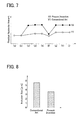
- FIG. 7 is a graph showing the residual austenite amounts in each manufacturing step shown in FIG. 1 . Signs (a) to (i) in the horizontal axis represent the above manufacturing steps. The vertical axis represents the residual austenite amounts indicated by volume percentages (%). The residual austenite amounts were measured by analysis of metal crystal structure by use of an X-ray diffractometer.
- An alloy composition ratio (weight%) of maraging steel is that nickel (Ni) is about 18%, cobalt (Co) is about 9%, molybdenum (Mo) is about 5%, titanium (Ti) is about 0.45%, aluminum (Al) is about 0.1%, and carbon (C) is 0.03% or less.
- the residual austenite amount is almost constant and no increase is detected.
- the residual austenite amount increases nearly double in the melting-solidifying step (c), decreases once in the rolling step (f), and returns to the previous increased residual austenite amount in the second solution treatment step (g), and subsequently does not vary in particular.
- FIG. 8 is a graph showing the size of non-metallic inclusion before and after the melting-solidifying step of the manufacturing process shown in FIG. 1 .
- the size of the TiN inclusion does not change.
- This measurement result is interpreted as the TiN inclusion size in the endless metal ring 10.
- the alloy composition ratio (weight %) of maraging steel is similar to that in the above measurement of the residual austenite amount.
- the TiN inclusion size is measured in such a manner that 5 gram of a material is extracted and dissolved in acid, and then the material filtered with a 3- ⁇ m filter is observed through an electronic microscope. Based on the measurement result, a maximum inclusion size is estimated by an extremal statistics method.
- a conventional inclusion size shown in FIG. 8 is the maximum inclusion size extracted from the material before the melting-solidifying step (c), which is about 5.8 ⁇ m.
- the inclusion size in the present embodiment according to the invention is the maximum inclusion size extracted from the material after the melting-solidifying step (c), which is about 3.6 ⁇ m. This reveals that the maximum inclusion size greatly decreases in the melting-solidifying step (c). It is thus clear that the effect of suppressing fatigue failure which initiate at inclusion.
- FIG. 9 is a graph (S-N curves) representing fatigue life of the endless metal ring manufactured in the manufacturing process shown in FIG 1 .
- the vertical axis represents load stress (stress amplitude) and the horizontal axis represents the number of repetitions to failure.
- the horizontal axis is a logarithmic scale.
- the fatigue life of the endless metal ring 10 manufactured in the manufacturing method of the present embodiment according to the invention is increased about two or three times longer than the conventional one. Even when the load stress (stress amplitude) is increased, that tendency remains unchanged. In recent years, therefore, the endless metal ring 10 is also very effective in increasing a gear ratio range in the CVT in order to further improve the fuel efficiency.
- the endless metal ring 10 is made of low carbon alloy steel (maraging steel) containing molybdenum.
- the ring element 5 is formed, over its entire circumference or in a part continuous in the circumferential direction, with the molybdenum segregated area in which the molybdenum with a high melting point is preferentially solidified. In the molybdenum segregated area, much austenite phases are left. Austenite transforms into martensite (deformation induced martensite) under external stress. At that time, the crystal structure changes from a face-centered cubic lattice to body-centered cubic lattice with an expanded volume.
- compression stress acts on crystal grain boundary that is likely to be cracked. This can suppress development of cracks against external stress. That is, the austenite phase left in the molybdenum segregated area formed in the melted-solidified layers 4 (41, 42, 43) provides an effect of suppressing crack growth or development.
- the non-metallic inclusion such as TiN contained in the material is refined in the course of solidification by rapid cooling. Because of refining of the non-metallic inclusion, the non-metallic inclusion which may initiate inner crack(s) is significantly decreased. Specifically, the melted-solidified layers 4 (41, 42, 43) formed by local heating can also provide an effect of reducing cracks that initiate at inclusion in a very high cycle region (a region exceeding 10 7 cycles).
- the endless metal ring 10 produced from the ring elements 5 formed with the melted-solidified layers 4 (41, 42, 43) on its entire circumference or in a part continuous in the circumferential direction is formed with the molybdenum segregated area in which much austenite phases are left and also the non-metallic inclusion which may initiate cracks is reduced, thus largely improving the fatigue strength.
- the melted-solidified layers 4 (41, 42, 43) are formed on the outer circumference of the annular member 1 made of maraging steel containing molybdenum.
- molybdenum (Mo) with a higher melting point than other alloy elements is preferentially solidified, forming a segregated area(s).
- Molybdenum is an austenite stabilizing element and therefore the molybdenum segregated area contains much residual austenite phases in portions where austenite should inherently transform into martensite.
- the ring element 5 Since the melted-solidified layers 4 (41, 42, 43) are arranged to be continuous in the circumferential direction of the ring element 5, the ring element 5 is formed with the molybdenum segregated area continuous in the circumferential direction. That is, the residual austenite phases left by the molybdenum segregated area are formed to be continuous in the circumferential direction of the ring element 5.
- Austenite partially transforms into martensite (deformation induced martensite) under pressure from outside. At that time, a crystal structure changes from a face-centered cubic lattice to a body-centered cubic lattice with an expanded volume. Thus, compression stress acts on a crystal grain boundary that is likely to be cracked. This can suppress development of cracks against external stress.
- the amount of residual austenite at that time is preferably on the order of 2 to 3% by volume which is effective for fatigue property.
- the present invention can realize this.
- the endless metal ring 10 manufactured by the above method can provide greatly increased fatigue life even when a constant stress amplitude repeatedly acts on the endless metal ring 10.
- the molybdenum segregated area can be formed without deforming the annular member 1.
- the melted-solidified layers 4 (41, 42, 43) are cooled immediately after they are melted. Accordingly, although the non-metallic inclusion such as TiN contained in a row material is dissolved in the course of melting, the cooling speed in the course of solidifying is fast and thus the growth of non-metallic inclusion during recrystallization is suppressed, thereby prompting refining. This refining of non-metallic inclusion enables suppression of fatigue failure which is apt to initiate at inclusion. Consequently, the fatigue life of the endless metal ring 10 can be further improved.
- the circular or spiral width and feed pitch are arbitrarily set so that the melted-solidified layers 42 and 43 are formed in the annular member over the entire circumference or in the part continuous in the circumferential direction.
- the outer circumference of the ring element 5 can be formed with the melted-solidified layers 42 and 43 of at least one turn.
- the molybdenum segregated area can be formed on the entire circumference of the ring element 5 or may be formed only in a part desired for strengthening. This can ensure a predetermined residual austenite amount nearly equal in a predetermined width in the circumferential direction to improve the fatigue strength of the endless metal ring 10.
- the predetermined residual austenite amount in the axial end portions 53 of the ring element 5 can be endured nearly equal in the circumferential direction.
- the stress amplitude during use of the endless metal ring 10 in a CVT largely acts on the axial end portions 53 more than an axial central portion of the endless metal ring 10.
- the predetermined residual austenite amount can be ensured to be nearly equal in the circumferential direction in the axial end portions 53 of the endless metal ring 10 on which the stress amplitude will largely acts. This can effectively improve the fatigue strength of the endless metal ring 10.
- the melted-solidified layers 4 are formed of the plurality of linear melted-solidified layers 41 formed by heating and cooling the outer circumference of the annular member 1 in the axial direction so that adjacent ones of the layers 41 are continuous with each other.
- the predetermined residual austenite amount can be ensured to be nearly equal in the entire outer circumference of the annular member.
- the predetermined residual austenite amount can be ensured nearly equal in the entire circumference of the severed ring element 5 having a predetermined width.
- the linear melted-solidified layers 41 are to be formed so that adjacent ones are continuous with each other, they do not always need to be continuous on the inner circumference side of the annular member 1 as long as the outer circumference side is continuous. This is because, in a case where the endless metal ring 10 is used in a CVT, the stress amplitude more largely acts on the outer circumferential side than on the inner circumferential side of the endless metal ring 10.
- the forced cooling can shorten the solidification time, thereby enabling forming the melted-solidified layers 4 (41, 42, 43) while maintaining the outer shape and thickness of the annular member 1. Since the re-crystallization speed of TiN and others in the course of solidification is fast, the growth of non-metallic inclusion is suppressed and thus refining can be further prompted. In addition, this further prompted refining of non-metallic inclusion can suppress the fatigue failure which is likely to initiate at inclusion. This makes it possible to further improve the fatigue life of the endless metal ring 10.
- the heating is laser heating or plasma heating
- alloy steel containing alloy elements e.g., molybdenum
- high heat input density and high melting point melts at high speed, thereby enabling forming the melted-solidified layers 4 (41, 42, 43) in a short time on the outer circumference of the annular member 1 made of maraging steel containing molybdenum.
- the productivity of the endless metal ring 10 is not inhibited.
- the laser heating or plasma heating is local heating and cooling, the refining of the non-metallic inclusion is prompted, thus suppressing fatigue failure which may initiate at inclusion.
- the annular member 1 is formed by joining the ends of a plate material made of maraging steel.
- This annular member 1 can be easily manufactured with an arbitrary outer diameter.
- This joining method includes diffusion joining and others as well as laser welding or plasma welding.
- annular member 1 is formed by extrusion molding of a billet made of maraging steel, a seamless annular member 1 can be manufactured. Since the seamless annular member 1 made of maraging steel containing molybdenum is formed, the residual austenite is left to be continuous in a more uniform amount in the circumferential direction in the molybdenum segregated area formed by melting and solidifying.
- the retaining device 7 retaining the annular member 1 rotatably in the circumferential direction and the local heating device 3 placed to aim at the outer circumferential surface of the annular member 1.
- the melted-solidified layers 4 (41, 42, 43) can be formed in a short time to be continuous on the outer circumference of the annular member with a simple device.
- the retaining device 7 is configured to continuously rotate the annular member 1 in order to form the melted-solidified layers 42 or 43 in circular or spiral form and to intermittently rotate the annular member 1 in order to form a plurality of linear melted-solidified layers 41. Movement of the annular member 1 in the axial direction can be performed by the retaining device 7. Instead of moving the annular member 1 in the axial direction, the torch 31 of the local heating device 3 may be moved or swung.
- the endless metal ring 10 to be used in a vehicle CVT is made of low carbon alloy steel containing molybdenum and the ring element is melted and solidified over the entire circumference or in the part continuous in the circumferential direction, the molybdenum segregated area is formed in the entire circumference or the part continuous in the circumferential direction of the endless metal ring 10. Since molybdenum is an austenite stabilizing element, much austenite phases are left in the molybdenum segregated area. Austenite transforms into martensite (deformation induced martensite) under external stress. At that time, the crystal structure changes from a face-centered cubic lattice to a body-centered cubic lattice with an expanded volume.
- the endless metal ring 10 can provide greatly increased fatigue life even when constant stress amplitude repeatedly acts on the endless metal ring 10.
- the low carbon alloy steel forms less thermally transformed martensite, and thus can avoid an increase in hardness more than necessary and maintain predetermined elongation.
- the low carbon alloy steel is maraging steel, the excellent strength characteristic can be ensured by the aging treatment.
- the above embodiments shows that the melted-solidified layers 4 (41, 42, 43) formed on the outer circumference of the annular member 1 are formed to penetrate from the outer circumference 11 to the inner circumference 12 of the annular member 1, they are not always necessary formed to penetrate to the inner circumference 12 of the annular member 1.
- the stress amplitude that will act on the endless metal ring 10 used in a CVT is larger on the outer circumference side of the endless metal ring 10 than on the inner circumference side.
- the melted-solidified layers 4 (41, 42, 43) can be formed in a shorter time and thus the productivity can be further improved.
- the present invention is utilizable to a method and device for manufacturing an endless metal ring that will constitute a drive belt to circularly turn between a drive shaft pulley and a driven shaft pulley of a vehicle, a manufacturing device, and an endless metal ring.
Landscapes
- Engineering & Computer Science (AREA)
- Mechanical Engineering (AREA)
- Chemical & Material Sciences (AREA)
- General Engineering & Computer Science (AREA)
- Physics & Mathematics (AREA)
- Materials Engineering (AREA)
- Crystallography & Structural Chemistry (AREA)
- Metallurgy (AREA)
- Organic Chemistry (AREA)
- Optics & Photonics (AREA)
- Plasma & Fusion (AREA)
- Thermal Sciences (AREA)
- Heat Treatment Of Articles (AREA)
Abstract
Description
- The present invention relates to a method for manufacturing an endless metal ring to be used for power transmitting of a continuously variable transmission of a vehicle and a manufacturing device thereof, and the endless metal ring.
- As a continuously variable transmission (CVT) mounted in a vehicle, for example, there is used a belt-type CVT arranged such that an endless metal belt consisting of a plurality of stacked endless metal rings and a plurality of elements engaged with the rings, the endless metal ring being circumferentially moveable between a drive shaft pulley and a driven shaft pulley. This CVT can continuously change a transmission gear ratio in stepless manner, differently from a multistage transmission that shifts gears by changing combinations of gears. Thus, the CVT has superior fuel efficiency. In recent years, a gear ratio range tends to be increased for the purpose of further improving the fuel efficiency. However, such an increased gear ratio range causes an increase in load applied to the belt. Thus, a stronger endless metal ring than at present is demanded.
- In general, as a material used for manufacturing an endless metal ring, there is known maraging steel having excellent strength characteristics. In order to increase the strength (in particular, fatigue strength) of an endless metal ring made of this maraging steel, there is disclosed a technique to generate reverse-transformed austenite phase by heating the endless metal ring in a specific range (about 500 to 750°C) of a lower temperature than an austenitizing start temperature of about 750°C (see
Patent Documents - On the other hand, a factor that lowers the fatigue limit of the endless metal ring made of maraging steel in a very high cycle region (a region exceeding 107 cycles) is known as initiating at inner inclusions (TiN and others). Accordingly, a technique is disclosed in which raw material for Ti-containing steel (e.g., maraging steel) free from TiN inclusions is melted in a vacuum induction furnace and is cast as an electrode, and the thus obtained Ti-containing steel is re-melted by a vacuum arc melting method, thereby refining or miniaturizing the TiN inclusions (e.g., see Patent Document 3).
-
- Patent Document 1:
JP-A-2002-3946 - Patent Document 2:
JP-A-2004-315875 - Patent Document 3:
JP-A-2001-214212 - However, when a large amount of the reverse-transformed austenite phase is generated (15 to 25% by volume or 25 to 35% by volume) as in the techniques in
Patent Documents - However, it is necessary to hold the aging temperature at about 480°C for 100 hours or more or at about 530°C for 7 hours or more to stably control the residual austenite amount of on the order of 2 to 3% by volume by utilizing reverse transformation. Either case results in largely deteriorated productivity. In this case, a high temperature of about 600°C is conceivable to enable a short-time treatment; however, this causes a problem that a nitride state varies or the austenite amount varies even under the same nitriding conditions, and thus stable strength could not be ensured.
- In mass-production facilities in which re-melting by the vacuum arc melting method is conducted as in the technique of
Patent Document 3, a cooling speed is generally slow and it is difficult to stably refine the size of the non-metallic inclusions to about 7 µm or less which is the size less likely to initiate fatigue failure. To increase the cooling speed in the mass-production facilities using re-melting by the vacuum arc melting method, it is preferable to reduce an amount of the material to be melted. However, this method greatly deteriorates the productivity and thus is not practical. Furthermore, in view of costs, it is not preferable to use high quality raw material free from non-metallic inclusions. - The present invention has been made to solve the above problems and has a purpose to provide a method for manufacturing an endless metal ring, capable of refining a non-metallic inclusion to improve fatigue strength while ensuring a predetermined residual austenite amount without impeding the productivity, a manufacturing device, and an endless metal ring.
- (1) To achieve the above purpose, one aspect of the invention provides a method of manufacturing an endless metal ring by cutting an annular member made of maraging steel containing molybdenum into a ring element having a predetermined width, wherein the method includes forming a melted-solidified layer on an outer circumference of the annular member so that the melted-solidified layer is arranged to be continuous in a circumferential direction.
- According to the above aspect in which the melted-solidified layer is formed on the outer circumference of the annular member made of maraging steel containing molybdenum, molybdenum (Mo) having a higher melting point than other alloy elements is preferentially solidified on the melted-solidified layer, forming a segregated area. Molybdenum is an austenite stabilizing element and thus the molybdenum segregated area contains much residual austenite phases in portions where austenite should inherently transform into martensite.
- Since the melted-solidified layer is formed to be continuous in the circumferential direction of the ring element, the ring element is formed with the molybdenum segregated area continuous in the circumferential direction. That is, the residual austenite phases left by the molybdenum segregated area are formed to be continuous in the circumferential direction of the ring element. Austenite partially transforms into martensite (deformation induced martensite) under pressure from outside. At that time, a crystal structure changes from a face-centered cubic lattice to a body-centered cubic lattice with an expanded volume. Thus, compression stress acts on crystal grain boundary that is likely to be cracked. This can suppress development of cracks against external stress. The amount of residual austenite at that time is preferably on the order of 2 to 3% by volume which is effective for fatigue property. The present invention can realize this. The endless metal ring manufactured by the above method can provide greatly increased fatigue life even when constant stress amplitude repeatedly acts on the endless metal ring.
- (2) In the method for manufacturing an endless metal ring set forth in (1), preferably, the melted-solidified layer is formed by locally heating and cooling the outer circumference of the annular member.
- According to the above configuration, since the melted-solidified layer is formed by locally heating and cooling the outer circumference of the annular member, the molybdenum segregated area can be formed without deforming the annular member.
- Because of the local heating and cooling, the melted-solidified layer is cooled immediately after it is melted. Accordingly, although the non-metallic inclusion such as TiN contained in a row material is dissolved in the course of melting, the cooling speed in the course of solidifying is fast and thus the growth of non-metallic inclusion during recrystallization is suppressed, thereby prompting refining. This refining of non-metallic inclusion enables suppression of fatigue failure which may initiate at the inclusion. The fatigue life of the endless metal ring can be further improved.
- In this case, because of the local heating and cooling, it is unnecessary to perform re-melting in a raw-material manufacturing step as in the technique of
Patent Document 3 and there is less influence on productivity. Furthermore, limitation to use only the high-pure raw material is reduced, contributing to cost reduction. The solution (annealing) heat treatment is performed after the melting-solidifying step as needed. This can uniformize molybdenum in the molybdenum segregated area. - (3) In the method for manufacturing an endless metal ring set forth in (1) or (2), preferably, the melted-solidified layer is formed by spirally or circularly heating and cooling the outer circumference of the annular member.
- According to the above configuration, since the melted-solidified layer is formed by spirally or circularly (circumferentially) heating and cooling the outer circumference of the annular member, the spiral or circular width and feed pitch are arbitrarily set so that the melted-solidified layer is formed in the annular member over the entire circumference or in the part continuous in the circumferential direction. For instance, when the spiral or circular width and feed pitch are set within the width of the ring element, the outer circumference of the ring element can be formed with the melted-solidified layer of at least one turn. Thus, the molybdenum segregated area can be formed on the entire circumference of the ring element or may be formed only in a part desired for strengthening. This can ensure a predetermined residual austenite amount nearly equal in a predetermined width in the circumferential direction to improve the fatigue strength of the endless metal ring.
- (4) In the method for manufacturing an endless metal ring set forth in (3), preferably, the melted-solidified layer is formed in an end of the ring element in an axial direction.
- According to the above configuration, since the melted-solidified layer is formed in the axial end portion of the ring element, the predetermined residual austenite amount in the axial end portion of the ring element can be endured nearly equal in the circumferential direction. The stress amplitude during use of the endless metal ring in a CVT largely acts on the axial end portion more than an axial central portion of the endless metal ring. Thus, the predetermined residual austenite amount can be ensured to be nearly equal in the circumferential direction in the axial end portion of the endless metal ring on which the stress amplitude will largely acts. This can effectively improve the fatigue strength of the endless metal ring.
- (5) In the method for manufacturing an endless metal ring set forth in (1) or (2), preferably, the melted-solidified layer is formed of a plurality of linear melted-solidified layers formed by heating and cooling the outer circumference of the annular member in an axial direction so that adjacent ones of the linear melted-solidified layers are continuous with each other.
- According to the above configuration, since the melted-solidified layer is formed of a plurality of linear melted-solidified layers formed by heating and cooling the outer circumference of the annular member in the axial direction so that adjacent ones of the linear melted-solidified layers are continuous with each other. Thus, the predetermined residual austenite amount can be ensured to be nearly equal in the entire outer circumference of the annular member. Accordingly, the predetermined residual austenite amount can be ensured nearly equal in the entire circumference of the severed ring element having a predetermined width. Herein, when the linear melted-solidified layers are to be formed so that adjacent ones are continuous with each other, they do not always need to be continuous on the inner circumference side of the annular member as long as they are continuous on the outer circumference side. This is because, in a case where the endless metal ring is used in a CVT, the stress amplitude more largely acts on the outer circumferential side than on the inner circumferential side of the endless metal ring.
- (6) In the method for manufacturing an endless metal ring set forth in any one of (2) to (5), preferably, the cooling is forcibly performed.
- According to the above configuration, the forced cooling can shorten the solidification time, thereby enabling forming the melted-solidified layer while maintaining the outer shape and thickness of the annular member. Since the re-crystallization speed of TiN and others in the course of solidification is fast, the growth of non-metallic inclusion is suppressed and thus refining can be further prompted. In addition, this further prompted refining of non-metallic inclusion can suppress the fatigue failure which is likely to initiate at inclusion. This makes it possible to further improve the fatigue life of the endless metal ring.
- (7) In the method for manufacturing an endless metal ring set forth in any one of (2) to (6), preferably, the heating is laser heating or plasma heating.
- According to the above configuration, since the heating is laser heating or plasma heating, even alloy steel containing alloy elements (e.g., molybdenum) with heat input density and high melting point melts at high speed, thereby enabling forming the melted-solidified layer in a short time on the outer circumference of the annular member made of maraging steel containing molybdenum. Thus, the productivity of the endless metal ring is not inhibited. Since the laser heating or plasma heating is local heating and cooling, the refining of the non-metallic inclusion is prompted, thus suppressing fatigue failure which may initiate at inclusion.
- (8) In the method for manufacturing an endless metal ring set forth in any one of (1) to (7), preferably, the annular member is formed by joining end portions of a plate material made of the maraging steel.
- According to the above configuration, the annular member is formed by joining the ends of a plate material made of maraging steel. This annular member can be easily manufactured with an arbitrary outer diameter. This joining method includes diffusion joining and others as well as laser welding or plasma welding.
- (9) In the method for manufacturing an endless metal ring set forth in any one of (1) to (8), preferably, the annular member is formed by extrusion-molding a billet made of the maraging steel.
- According to the above configuration, since the annular member is formed by extrusion molding of a billet made of maraging steel, a seamless annular member can be manufactured. Since the seamless annular member made of maraging steel containing molybdenum is formed, the residual austenite is left to be continuous in a more uniform amount in the circumferential direction in the molybdenum segregated area formed by melting and solidifying.
- (10) To achieve the above purpose, another aspect of the invention provides a device of manufacturing an endless metal ring, the device being to be used in the method of manufacturing an endless metal ring according to any one of
claims 1 to 9, wherein the device includes a retaining device for retaining the annular member rotatably in a circumferential direction, and a local heating device that will be placed to aim at an outer circumferential surface of the annular member. - According to the above configuration, it is sufficient to provide the retaining device for retaining the annular member rotatably in the circumferential direction and the local heating device placed to aim at the outer circumferential surface of the annular member. Thus, the melted-solidified layer can be formed in a short time to be continuous on the outer circumference of the annular member with a simple device. For instance, the retaining device is configured to continuously rotate the annular member in order to form the melted-solidified layer in spiral or circular form and to intermittently rotate the annular member in order to form a plurality of linear melted-solidified layers. Movement of the annular member in the axial direction can be performed by the retaining device. Instead of moving the annular member in the axial direction, a torch of the local heating device may be moved or swung.
- (11) To achieve the above purpose, another aspect of the invention provides an endless metal ring to be used in a continuously variable transmission for a vehicle, wherein the endless metal ring is made of low carbon alloy steel containing molybdenum, and a ring element is melted and solidified over an entire circumference or in a part continuous in a circumferential direction.
- According to the above aspect, the endless metal ring to be used in a continuous variable transmission (CVT) for a vehicle is made of low carbon alloy steel containing molybdenum and the ring element is melted and solidified over the entire circumference or in a part continuous in the circumferential direction. Thus, the molybdenum segregated area is formed in the entire circumference or the part continuous in the circumferential direction of the endless metal ring. Since molybdenum is an austenite stabilizing element, much austenite phases are left in the molybdenum segregated area. Austenite transforms into martensite (deformation induced martensite) under external stress. At that time, the crystal structure changes from a face-centered cubic lattice to a body-centered cubic lattice with an expanded volume. Thus, compression stress acts on crystal grain boundary that is likely to be cracked. This can suppress development of cracks against external stress. Consequently, the endless metal ring can provide greatly increased fatigue life even when constant stress amplitude repeatedly acts on the endless metal ring. It is to be noted that the low carbon alloy steel forms less thermally transformed martensite, and thus can avoid an increase in hardness more than necessary and maintain predetermined elongation. According to the above configuration, it is possible to make sure the predetermined residual austenite amount continuous in the circumferential direction of the endless metal ring while maintaining the predetermined hardness and elongation, and improve fatigue strength to the stress amplitude repeatedly acting in the circumferential direction.
- (12) In the endless metal ring set forth in (11), preferably, the low carbon alloy steel is maraging steel.
- According to the above configuration, since the low carbon alloy steel is maraging steel, the excellent strength characteristic can be ensured by the aging treatment.
- According to the invention, it is possible to refine non-metallic inclusions and improve fatigue strength while ensuring a predetermined residual austenite amount without inhibiting productivity.
-
-
FIG. 1 is a manufacturing process of an endless metal ring in an embodiment according to the invention; -
FIG. 2 is a detailed view of a melting-solidifying step of the manufacturing process shown inFIG. 1 ; -
FIG. 3 is a detailed view of another melting-solidifying step of the manufacturing process shown inFIG. 1 ; -
FIG. 4 is a detailed view of another melting-solidifying step of the manufacturing process shown inFIG. 1 ; -
FIG. 5 is a schematic cross sectional view of a melted-solidified layer formed in an annular member in the melting-solidifying step shown inFIG. 1 ; -
FIG. 6 is a schematic cross sectional view of the melted-solidified layer formed in end portions of a ring element in an axial direction in the melting-solidifying step shown inFIG. 1 ; -
FIG. 7 is a graph showing residual austenite amount in each step of the manufacturing process shown inFIG. 1 ; -
FIG. 8 is a graph showing non-metallic inclusion size before and after the melting-solidifying step of the manufacturing process shown inFIG. 1 ; -
FIG. 9 is a graph (S-N curves) showing fatigue life of endless metal rings manufactured in the manufacturing process shown inFIG. 1 ; and -
FIG. 10 is an overall view of the endless metal ring manufactured in the manufacturing process shown inFIG. 1 . - A detailed description of preferred embodiments of a method and a device for manufacturing an endless metal ring, and the endless metal ring, according to the present invention will now be given referring to the accompanying drawings.
FIG. 1 shows a manufacturing process of an endless metal ring in the present embodiment according to the invention.FIGs. 2 to 4 are detailed views each showing a melting-solidifying step of the manufacturing process shown inFIG. 1 .FIG. 5 is a schematic cross sectional view of a melted-solidified layer formed in an annular member in the melting-solidifying step shown inFIG. 1 .FIG. 6 is a schematic cross sectional view of the melted-solidified layer formed in end portions of a ring element in an axial direction in the melting-solidifying step shown inFIG. 1 . - As shown in
FIG. 1 , the manufacturing process of the endless metal ring includes (a) a step of forming an annular member, (b) a joining step, (c) a melting-solidifying step, (d) a first solution treatment (annealing) step, (e) a ring cutting step, (f) a rolling step, (g) a second solution treatment step, (h) a circumferential length adjustment step, and (i) an aging and nitriding step. The following explanation is given with a focus on the step (a) of forming an annular member, the joining step (b), and the melting-solidifying step (c), which are the distinctive features of the invention, and other remaining steps will be explained in case of necessity. - This annular-member forming step (a) is a step to form a cylindrical body having a predetermined length in an axial direction and opening in the axial direction. This annular-member forming step is achieved by a cutting and bending method of cutting a coiled band steel to a sheet and then bending the cut sheet, an extrusion molding method of extrusion-molding a predetermined billet, a pipe cutting method of cutting a pipe-shaped steel pipe, or the like. For instance, in the cutting and bending method shown in
FIG. 1 (a) , a band-shaped maraging steel sheet or plate Z is wound off from a coil and cut into a predetermined sized sheet material ZS, and then bending the sheet so that edge ends abut on each other. The bending is performed by use of a roll or a die. In the extrusion molding method (not shown), a billet formed in a hollow shape is inserted in a container, a mandrel (a core rod) is inserted in the billet, and then the billet is pressed with a ram to be extruded from an opening of the die to mold an annular member. At that time, the billet, the ram, and others are preferably heated at on the order of 1000 to 1300°C. This is to enhance plastic flowability of the billet, thereby enabling reducing extrusion load. - The thickness of the
annular member 1 is on the order of 0.4 to 0.5 mm. The diameter of theannular member 1 is on the order of 100 to 200 mm. The maraging steel used in the present embodiment inevitably contains iron, nickel, and molybdenum and also additionally contains cobalt, titanium, aluminum, and others as needed. The content of nickel in the maraging steel is not limited to 18 weight% and may be on the order of 20 to 25 weight%. The content of molybdenum is preferably at least 3 weight% or more. If nickel is increased, the austenite phase is easily formed. However, if molybdenum higher in melting point than other alloy elements is not contained to a certain degree, the molybdenum segregated area is less likely to be formed in the course of solidification. - The joining step (b) is a step to join the ends to each other when the annular-member forming step uses the cutting and bending method. This joining method includes a welding method to weld the ends to each other, a method of removing oxidation coating of the ends and diffusion joining them, and other methods. In the welding method shown in
FIG. 1 (b) , awelding device 2 is placed to face anabutting part 13 of theannular member 1, moving theannular member 1 or a torch of thewelding device 2 in an axial direction (a direction indicated by an arrow F) to perform abutting welding. Suitable for thewelding device 2 is for example a laser welding device or a plasma welding device capable of locally melting. In case shrinkage occurs in a boundary between aweld portion 21 and abase material 22, it causes strength degradation. Thus, such a welding condition (spot diameter, focus distance, welding speed, etc.) as not to cause shrinkage are selected. In a case where the annular-member forming step uses the extrusion molding method or the pipe cutting method, the joining step is naturally omitted. - The melting-solidifying step (c) is a step of heating and cooling from the outer circumference side of the
annular member 1 by alocal heating device 3 placed above the outer circumference of theannular member 1 to aim at it, hereby continuously forming melted-solidified layers 4 (41, 42, 43) on the outer circumference of theannular member 1. As the method of forming the melted-solidified layers, various methods are available as shown inFIGs. 2 to 4 . Thelocal heating device 3 is preferably the laser welding device or plasma welding device used in thewelding device 2. In addition to cost reduction resulting from commonality of facilities, the molybdenum segregated area in the melted-solidified layers 4 can be formed to nearly equal to theweld portion 21. Thus, a segregated amount of the molybdenum segregated area can be made nearly uniform in the circumferential direction. - As shown in
FIGs. 2 to 4 , thelocal heating device 3 includes aheating torch 31 and a coolingnozzle 32. Theheating torch 31 is put face-to-face with and at a predetermined distance from the outer circumference of theannular member 1 in a normal direction. The diameter of heat input from theheating torch 31 is preferably set to be larger than that during welding. This is because since the abuttingpart 13 having a slight gap is melted during welding, sag or burn-through of molten metal may be caused, whereas such a trouble is less caused in the melted-solidified layers 4 and a processing time can be shortened. However, if the diameter of heat input from theheating torch 31 is too large, it may deform the shape of theannular member 1 and thus it is preferable to select an appropriate heat input diameter causing no deformation due to continuous melting and solidifying. - As shown in
FIGs. 2 to 4 , thelocal heating device 3 includes the coolingnozzle 32 adjacent to and behind theheating torch 31 in a feed direction. The coolingnozzle 32 is inclined so that its lower end is closer to theheating torch 31. The coolingnozzle 32 is arranged to inject inert gas such as compression air, nitrogen gas, and argon gas to forcibly rapidly cool a portion melted by theheating torch 31. - As the forced cooling method, there is also a method of cooling the
annular member 1 from the inner circumference side thereof, instead of using theabove cooling nozzle 32. In one example of such methods, a retainingdevice 7 for retaining the inner circumference side of theannular member 1 is provided with a recirculation pipe (not shown) for recirculating cooling water. If the amount of heat input from theheating torch 31 is small, self-cooling may be adopted instead of forced cooling. - The method shown in
FIG. 2 is a method of forming linear melted-solidifiedlayers 41 each extending along the axial direction of theannular member 1. By moving the retainingdevice 7 retaining theannular member 1 in the axial direction (in a direction indicated by an arrow F), each linear melted-solidifiedlayer 41 is formed to extend continuously from a front end to a rear end of theannular member 1. Those linear melted-solidifiedlayers 41 are formed to overlap one another so thatadjacent layers 41 are continuous in the circumferential direction. To overlap theadjacent layers 41 one on another, the retainingdevice 7 rotates theannular member 1 by a fixed angle in the circumferential direction every time onelayer 41 is formed. Since those linear melted-solidifiedlayers 41 are formed in symmetric positions with respect to the axis of the annular member 1 (i.e., in half-turn, opposite positions), thelayers 41 are less likely to be affected by the heat-input temperature in respectiveadjacent layers 41. - The method shown in
FIG. 3 is a method of forming a plurality of annular melted-solidifiedlayers 42 at predetermined intervals in the axial direction. Each of the annular melted-solidifiedlayers 42 is formed by rotating, one turn, a rotary shaft of the retainingdevice 7 retaining theannular member 1 in the circumferential direction (in the direction indicated by the arrow R). In the case of using the welding method in the joining step inFIG. 1 (b) , thelayers 42 are formed to intersect with theweld portion 21 extending in the axial direction. At that time, theweld portion 21 is melted and solidified again, and thus thelayers 42 are each formed with a molybdenum segregated area continuous in the circumferential direction. Thelayers 42 may be formed over the entire circumference so as to makeadjacent layers 42 overlap each other. Alternatively, they may be formed only in a site targeted for strengthening. -
FIG. 5 (a Q-Q cross section inFIG. 3 ) schematically shows a state where the adjacent annular melted-solidifiedlayers 42 overlap each other. As shown inFIG. 5 , the annular melted-solidifiedlayers 42 are formed to penetrate from an outercircumferential surface 11 to an innercircumferential surface 12 of theannular member 1. Theannular member 1 is heated by thelocal heating device 3 placed above the outer circumference of theannular member 1 to aim it, so that eachlayer 42 is large on an outer circumference side A1 and small on an inner circumference side A2 of theannular member 1. At that time, a feed pitch P is set so that a lapping margin B between theadjacent layers 42 is enough to make thelayers 42 overlap at least on the outer circumference side A1. This is because, in use as the endless metal ring 10 (seeFIG. 10 ), the stress amplitude acting on the outer circumference side of theendless metal ring 10 is larger than on the inner circumference side, leading to large influence on fatigue strength. -
FIG. 6 (the Q-Q cross section inFIG. 3 ) schematically shows a state where the adjacent annular melted-solidifiedlayers 42 do not overlap and thelayers 42 are formed only in the sites targeted for strengthening. As shown inFIG. 6 , thelayers 42 are formed inend portions 53 of thering element 5 in the axial direction mentioned later. This is because, in use as the endless metal ring 10 (seeFIG. 10 ), the stress amplitude acting on theaxial end portions 53 of theendless metal ring 10 is larger than on an axial central portion, leading to large influence on fatigue strength. In this case, similarly, eachlayer 42 is formed to penetrate from anouter circumference 51 to aninner circumference 52 of thering element 5. Thering element 5 may be produced by cutting at the same time when thelayers 42 are formed in theaxial end portions 53. For instance, there is a method of simultaneously performing melting-solidifying and cutting of theaxial end portions 53 while supplying assist gas to a laser welding device. - The method shown in
FIG. 4 is a method of forming a spiral melted-solidifiedlayer 43 extending along the outer circumference of theannular member 1. Thislayer 43 is formed spirally on the outer circumference of theannular member 1 by moving the retainingdevice 7 retaining theannular member 1 at a feed speed V in the axial direction while rotating the rotary shaft of the retainingdevice 7 in the circumferential direction (the direction indicated by the arrow R). The spiral melted-solidifiedlayer 43 may be formed over the entire circumference so that adjacent portions, or adjacent turns, of thelayer 43 overlap each other, but instead may be formed only in a site targeted for strengthening. The concept of overlapping the adjacent portions of thespiral layer 43 each other is similar to in the case of the annular melted-solidified layers 42 (seeFIG. 5 ). Further, the concept of forming the spiral melted-solidifiedlayer 43 only in the site targeted for strengthening, without overlapping the adjacent portions of thespiral layer 43, is also basically similar to in the case of the annular melted-solidified layers 42 (seeFIG. 6 ). However, when the spiral melted-solidifiedlayer 43 is to be formed in theaxial end portions 53 of thering element 5, it is necessary to irregularly feed thelocal heating device 3 in the axial direction so that the feed speed V in the axial direction is nearly zero in a position corresponding to eachaxial end portion 53 of thering element 5. - The first solution treatment (annealing) step shown in
FIG. 1 (d) is a step of homogenizing the hardness of theannular member 1 that is partially increased in the course of welding and melting-solidifying. Thus, this first solution treatment (annealing) step has only to be performed as needed. The ring cutting step (e) is a step of severing thering element 5 with a width corresponding to theendless metal ring 10 in consideration of elongation in the subsequent rolling step. The rolling step (f) is a step of rolling the cut ring element with the predetermined width to a predetermined length required as a rolledring element 6. This rolling increases the hardness. The second solution treatment (g) is a step of recrystallizing the rolled structure of the rolledring element 6 to restore the metal crystal particle shape deformed in the rolling. The circumferential length adjustment step (h) is a step of calibrating the circumferential length required as the rolledring element 6 to enable stacking of a plurality ofring elements 6 to form theendless metal ring 10. The aging-nitriding step (i) is a step of performing an aging treatment to provide predetermined hardness of the rolledring element 6 whose circumferential length has been calibrated and a nitriding treatment to form a uniform nitride layer. The steps from the first solution treatment (annealing) step (d) to the aging-nitriding step (i) are conventionally known and thus their details are not explained herein. -
FIG. 10 shows theendless metal ring 10 manufactured in the above manufacturing process. As shown inFIG. 10 , a plurality ofelements 9 are engaged with theendless metal ring 10 consisting of a plurality of stackedring elements 6 to constitute anendless metal belt 100. Thisbelt 100 functions to transmit drive power between the drive shaft pulley C1 on a drive side and the driven shaft pulley C2 on a driven side. Accordingly, theendless metal ring 10 is repeatedly subjected to bending deformation in passing over each of the pulleys C1 and C2, and is subjected to repeated tensile stress. An explanation is given below to the mechanism of how theendless metal ring 10 manufactured in the above manufacturing process has an improved fatigue strength as compared with an endless metal ring manufactured in a conventional manufacturing process. - The endless metal rings made of the maraging steel having the following components in the above manufacturing process were subjected to measurement of the austenite amounts in each step.
FIG. 7 is a graph showing the residual austenite amounts in each manufacturing step shown inFIG. 1 . Signs (a) to (i) in the horizontal axis represent the above manufacturing steps. The vertical axis represents the residual austenite amounts indicated by volume percentages (%). The residual austenite amounts were measured by analysis of metal crystal structure by use of an X-ray diffractometer. - An alloy composition ratio (weight%) of maraging steel is that nickel (Ni) is about 18%, cobalt (Co) is about 9%, molybdenum (Mo) is about 5%, titanium (Ti) is about 0.45%, aluminum (Al) is about 0.1%, and carbon (C) is 0.03% or less.
- As shown in
FIG. 7 , in the conventional manufacturing process, the residual austenite amount is almost constant and no increase is detected. In contrast, in the manufacturing process in the present embodiment according to the invention, the residual austenite amount increases nearly double in the melting-solidifying step (c), decreases once in the rolling step (f), and returns to the previous increased residual austenite amount in the second solution treatment step (g), and subsequently does not vary in particular. - This is conceived that when segregation of the alloy compositions (mainly, molybdenum) occurs in the course of melting-solidifying, austenite is stabilized in the segregated portion, the austenite remains left without transforming into martensite even when returned to room temperature. The residual austenite amount at that time is about 3% by volume. The residual austenite amount of about 2 to 3% by volume is a value whereby remarkable improvement of fatigue strength can be expected. In the rolling step (f), the rolling is performed at a rolling reduction of about 50%, so that martensitization of metastable austenite phase advances and thus the austenite amount temporarily decreases.
- Successively, TiN which is non-metallic inclusion was measured on inclusion size before and after the melting-solidifying step (c).
FIG. 8 is a graph showing the size of non-metallic inclusion before and after the melting-solidifying step of the manufacturing process shown inFIG. 1 . In the steps from the first solution treatment (annealing) step (d) to the aging-nitriding step (i), the size of the TiN inclusion does not change. Thus, this measurement result is interpreted as the TiN inclusion size in theendless metal ring 10. The alloy composition ratio (weight %) of maraging steel is similar to that in the above measurement of the residual austenite amount. - The TiN inclusion size is measured in such a manner that 5 gram of a material is extracted and dissolved in acid, and then the material filtered with a 3-µm filter is observed through an electronic microscope. Based on the measurement result, a maximum inclusion size is estimated by an extremal statistics method.
- A conventional inclusion size shown in
FIG. 8 is the maximum inclusion size extracted from the material before the melting-solidifying step (c), which is about 5.8 µm. On the other hand, the inclusion size in the present embodiment according to the invention is the maximum inclusion size extracted from the material after the melting-solidifying step (c), which is about 3.6 µm. This reveals that the maximum inclusion size greatly decreases in the melting-solidifying step (c). It is thus clear that the effect of suppressing fatigue failure which initiate at inclusion. - The reason why the maximum inclusion size greatly decreases at that time is presumed that the non-metallic inclusion such as TiN contained in the material is dissolved during melting and rapidly cooled by self-cooling or forced cooling due to local melting in the aforementioned melting-solidifying step (c), thereby suppressing growth of the non-metallic inclusion during re-crystallization in the course of solidification.
- Next, regarding the
endless metal ring 10 fabricated in the above manufacturing process, a result of a fatigue test (a dedicated test) on a ring alone is explained below.FIG. 9 is a graph (S-N curves) representing fatigue life of the endless metal ring manufactured in the manufacturing process shown inFIG 1 . The vertical axis represents load stress (stress amplitude) and the horizontal axis represents the number of repetitions to failure. The horizontal axis is a logarithmic scale. - As shown in
FIG. 9 , the fatigue life of theendless metal ring 10 manufactured in the manufacturing method of the present embodiment according to the invention is increased about two or three times longer than the conventional one. Even when the load stress (stress amplitude) is increased, that tendency remains unchanged. In recent years, therefore, theendless metal ring 10 is also very effective in increasing a gear ratio range in the CVT in order to further improve the fuel efficiency. - From the above details, the mechanism of improving the fatigue strength of the
endless metal ring 10 is briefly explained as below. Specifically, theendless metal ring 10 is made of low carbon alloy steel (maraging steel) containing molybdenum. Thering element 5 is formed, over its entire circumference or in a part continuous in the circumferential direction, with the molybdenum segregated area in which the molybdenum with a high melting point is preferentially solidified. In the molybdenum segregated area, much austenite phases are left. Austenite transforms into martensite (deformation induced martensite) under external stress. At that time, the crystal structure changes from a face-centered cubic lattice to body-centered cubic lattice with an expanded volume. Thus, compression stress acts on crystal grain boundary that is likely to be cracked. This can suppress development of cracks against external stress. That is, the austenite phase left in the molybdenum segregated area formed in the melted-solidified layers 4 (41, 42, 43) provides an effect of suppressing crack growth or development. - When the melted-solidified layers 4 (41, 42, 43) are formed by local heating, the non-metallic inclusion such as TiN contained in the material is refined in the course of solidification by rapid cooling. Because of refining of the non-metallic inclusion, the non-metallic inclusion which may initiate inner crack(s) is significantly decreased. Specifically, the melted-solidified layers 4 (41, 42, 43) formed by local heating can also provide an effect of reducing cracks that initiate at inclusion in a very high cycle region (a region exceeding 107 cycles).
- From the above, the
endless metal ring 10 produced from thering elements 5 formed with the melted-solidified layers 4 (41, 42, 43) on its entire circumference or in a part continuous in the circumferential direction is formed with the molybdenum segregated area in which much austenite phases are left and also the non-metallic inclusion which may initiate cracks is reduced, thus largely improving the fatigue strength. - As explained above in detail, according to the manufacturing method of the
endless metal ring 10 in the present embodiment, the melted-solidified layers 4 (41, 42, 43) are formed on the outer circumference of theannular member 1 made of maraging steel containing molybdenum. Thus, in the melted-solidified layers 4 (41, 42, 43), molybdenum (Mo) with a higher melting point than other alloy elements is preferentially solidified, forming a segregated area(s). Molybdenum is an austenite stabilizing element and therefore the molybdenum segregated area contains much residual austenite phases in portions where austenite should inherently transform into martensite. - Since the melted-solidified layers 4 (41, 42, 43) are arranged to be continuous in the circumferential direction of the
ring element 5, thering element 5 is formed with the molybdenum segregated area continuous in the circumferential direction. That is, the residual austenite phases left by the molybdenum segregated area are formed to be continuous in the circumferential direction of thering element 5. Austenite partially transforms into martensite (deformation induced martensite) under pressure from outside. At that time, a crystal structure changes from a face-centered cubic lattice to a body-centered cubic lattice with an expanded volume. Thus, compression stress acts on a crystal grain boundary that is likely to be cracked. This can suppress development of cracks against external stress. The amount of residual austenite at that time is preferably on the order of 2 to 3% by volume which is effective for fatigue property. The present invention can realize this. Theendless metal ring 10 manufactured by the above method can provide greatly increased fatigue life even when a constant stress amplitude repeatedly acts on theendless metal ring 10. - According to the present embodiment, since the melted-solidified layers 4, (41, 42, 43) are formed by locally heating and cooling the outer circumference of the
annular member 1, the molybdenum segregated area can be formed without deforming theannular member 1. - Because of the local heating and cooling, the melted-solidified layers 4 (41, 42, 43) are cooled immediately after they are melted. Accordingly, although the non-metallic inclusion such as TiN contained in a row material is dissolved in the course of melting, the cooling speed in the course of solidifying is fast and thus the growth of non-metallic inclusion during recrystallization is suppressed, thereby prompting refining. This refining of non-metallic inclusion enables suppression of fatigue failure which is apt to initiate at inclusion. Consequently, the fatigue life of the
endless metal ring 10 can be further improved. - In this case, because of the local heating and cooling, it is unnecessary to perform re-melting in a raw-material manufacturing step as in the technique of
Patent Document 3 and there is less influence on productivity. Furthermore, limitation to use only high-pure raw material is reduced, contributing to cost reduction. The solution (annealing) heat treatment is performed after the melting-solidifying step as needed. This can uniformize molybdenum in the molybdenum segregated area. - According to the present embodiment, since the melted-solidified
layers annular member 1, the circular or spiral width and feed pitch are arbitrarily set so that the melted-solidifiedlayers ring element 5, the outer circumference of thering element 5 can be formed with the melted-solidifiedlayers ring element 5 or may be formed only in a part desired for strengthening. This can ensure a predetermined residual austenite amount nearly equal in a predetermined width in the circumferential direction to improve the fatigue strength of theendless metal ring 10. - According to the present embodiment, since the melted-solidified
layers axial end portions 53 of thering element 5, the predetermined residual austenite amount in theaxial end portions 53 of thering element 5 can be endured nearly equal in the circumferential direction. The stress amplitude during use of theendless metal ring 10 in a CVT largely acts on theaxial end portions 53 more than an axial central portion of theendless metal ring 10. Thus, the predetermined residual austenite amount can be ensured to be nearly equal in the circumferential direction in theaxial end portions 53 of theendless metal ring 10 on which the stress amplitude will largely acts. This can effectively improve the fatigue strength of theendless metal ring 10. - According to the present embodiment, the melted-solidified layers 4 are formed of the plurality of linear melted-solidified
layers 41 formed by heating and cooling the outer circumference of theannular member 1 in the axial direction so that adjacent ones of thelayers 41 are continuous with each other. Thus, the predetermined residual austenite amount can be ensured to be nearly equal in the entire outer circumference of the annular member. Accordingly, the predetermined residual austenite amount can be ensured nearly equal in the entire circumference of the severedring element 5 having a predetermined width. Herein, when the linear melted-solidifiedlayers 41 are to be formed so that adjacent ones are continuous with each other, they do not always need to be continuous on the inner circumference side of theannular member 1 as long as the outer circumference side is continuous. This is because, in a case where theendless metal ring 10 is used in a CVT, the stress amplitude more largely acts on the outer circumferential side than on the inner circumferential side of theendless metal ring 10. - According to the present embodiment, the forced cooling can shorten the solidification time, thereby enabling forming the melted-solidified layers 4 (41, 42, 43) while maintaining the outer shape and thickness of the
annular member 1. Since the re-crystallization speed of TiN and others in the course of solidification is fast, the growth of non-metallic inclusion is suppressed and thus refining can be further prompted. In addition, this further prompted refining of non-metallic inclusion can suppress the fatigue failure which is likely to initiate at inclusion. This makes it possible to further improve the fatigue life of theendless metal ring 10. - According to the present embodiment, since the heating is laser heating or plasma heating, even alloy steel containing alloy elements (e.g., molybdenum) with high heat input density and high melting point melts at high speed, thereby enabling forming the melted-solidified layers 4 (41, 42, 43) in a short time on the outer circumference of the
annular member 1 made of maraging steel containing molybdenum. Thus, the productivity of theendless metal ring 10 is not inhibited. Since the laser heating or plasma heating is local heating and cooling, the refining of the non-metallic inclusion is prompted, thus suppressing fatigue failure which may initiate at inclusion. - According to the present embodiment, the
annular member 1 is formed by joining the ends of a plate material made of maraging steel. Thisannular member 1 can be easily manufactured with an arbitrary outer diameter. This joining method includes diffusion joining and others as well as laser welding or plasma welding. - According to the present embodiment, since the
annular member 1 is formed by extrusion molding of a billet made of maraging steel, a seamlessannular member 1 can be manufactured. Since the seamlessannular member 1 made of maraging steel containing molybdenum is formed, the residual austenite is left to be continuous in a more uniform amount in the circumferential direction in the molybdenum segregated area formed by melting and solidifying. - According to another embodiment, it is sufficient to provide the
retaining device 7 retaining theannular member 1 rotatably in the circumferential direction and thelocal heating device 3 placed to aim at the outer circumferential surface of theannular member 1. Thus, the melted-solidified layers 4 (41, 42, 43) can be formed in a short time to be continuous on the outer circumference of the annular member with a simple device. For instance, the retainingdevice 7 is configured to continuously rotate theannular member 1 in order to form the melted-solidifiedlayers annular member 1 in order to form a plurality of linear melted-solidified layers 41. Movement of theannular member 1 in the axial direction can be performed by the retainingdevice 7. Instead of moving theannular member 1 in the axial direction, thetorch 31 of thelocal heating device 3 may be moved or swung. - According to another embodiment of the invention, since the
endless metal ring 10 to be used in a vehicle CVT is made of low carbon alloy steel containing molybdenum and the ring element is melted and solidified over the entire circumference or in the part continuous in the circumferential direction, the molybdenum segregated area is formed in the entire circumference or the part continuous in the circumferential direction of theendless metal ring 10. Since molybdenum is an austenite stabilizing element, much austenite phases are left in the molybdenum segregated area. Austenite transforms into martensite (deformation induced martensite) under external stress. At that time, the crystal structure changes from a face-centered cubic lattice to a body-centered cubic lattice with an expanded volume. Thus, compression stress acts on crystal grain boundary that is likely to be cracked. This can suppress development of cracks against external stress. Consequently, theendless metal ring 10 can provide greatly increased fatigue life even when constant stress amplitude repeatedly acts on theendless metal ring 10. It is to be noted that the low carbon alloy steel forms less thermally transformed martensite, and thus can avoid an increase in hardness more than necessary and maintain predetermined elongation. According to the configuration of another embodiment of the invention, it is possible to make sure the predetermined residual austenite amount continuous in the circumferential direction of theendless metal ring 10 while maintaining the predetermined hardness and elongation, and improve fatigue strength to the stress amplitude repeatedly acting in the circumferential direction. - According to another embodiment, since the low carbon alloy steel is maraging steel, the excellent strength characteristic can be ensured by the aging treatment.
- The aforementioned embodiments may be changed without departing from the essential characteristics of the invention.
- For instance, although the above embodiments shows that the melted-solidified layers 4 (41, 42, 43) formed on the outer circumference of the
annular member 1 are formed to penetrate from theouter circumference 11 to theinner circumference 12 of theannular member 1, they are not always necessary formed to penetrate to theinner circumference 12 of theannular member 1. This is because the stress amplitude that will act on theendless metal ring 10 used in a CVT is larger on the outer circumference side of theendless metal ring 10 than on the inner circumference side. In this case, the melted-solidified layers 4 (41, 42, 43) can be formed in a shorter time and thus the productivity can be further improved. - The present invention is utilizable to a method and device for manufacturing an endless metal ring that will constitute a drive belt to circularly turn between a drive shaft pulley and a driven shaft pulley of a vehicle, a manufacturing device, and an endless metal ring.
-
- 1
- Annular member
- 2
- Welding device
- 3
- Local heating device
- 4
- Melted-solidified layer
- 5
- Ring element
- 6
- Rolled ring element
- 7
- Retaining device
- 9
- Element
- 10
- Endless metal ring
- 11
- Outer circumferential surface of annular member
- 12
- Inner circumferential surface of annular member
- 31
- Heating torch
- 32
- Cooling nozzle
- 41
- Linear melted-solidified layer
- 42
- Circular melted-solidified layer
- 43
- Spiral melted-solidified layer
- 53
- Axial end of ring element
- 100
- Endless metal belt
Claims (12)
- A method of manufacturing an endless metal ring by cutting an annular member made of maraging steel containing molybdenum into a ring element having a predetermined width,
wherein the method includes forming a melted-solidified layer on an outer circumference of the annular member so that the melted-solidified layer is arranged to be continuous in a circumferential direction. - The method of manufacturing an endless metal ring according to claim 1, wherein the melted-solidified layer is formed by locally heating and cooling the outer circumference of the annular member.
- The method of manufacturing an endless metal ring according to claim 1 or 2, wherein the melted-solidified layer is formed by spirally or circularly heating and cooling the outer circumference of the annular member.
- The method of manufacturing an endless metal ring according to claim 3, wherein the melted-solidified layer is formed in an end of the ring element in an axial direction.
- The method of manufacturing an endless metal ring according to claim 1 or 2, wherein the melted-solidified layer is formed of a plurality of linear melted-solidified layers formed by heating and cooling the outer circumference of the annular member in an axial direction so that adjacent ones of the linear melted-solidified layers are continuous with each other.
- The method of manufacturing an endless metal ring according to any one of claims 2 to 5, wherein the cooling is forcibly performed.
- The method of manufacturing an endless metal ring according to any one of claims 2 to 6, wherein the heating is laser heating or plasma heating.
- The method of manufacturing an endless metal ring according to any one of claims 1 to 7, wherein the annular member is formed by joining end portions of a plate material made of the maraging steel.
- The method of manufacturing an endless metal ring according to any one of claims 1 to 7, wherein the annular member is formed by extrusion-molding a billet made of the maraging steel.
- A device of manufacturing an endless metal ring, the device being to be used in the method of manufacturing an endless metal ring according to any one of claims 1 to 9,
wherein the device includes a retaining device for retaining the annular member rotatably in a circumferential direction, and
a local heating device that will be placed to aim at an outer circumferential surface of the annular member. - An endless metal ring to be used in a continuously variable transmission for a vehicle,
wherein the endless metal ring is made of low carbon alloy steel containing molybdenum, and
a ring element is melted and solidified over an entire circumference or in a part continuous in a circumferential direction. - The endless metal ring according to claim 11, wherein the low carbon alloy steel is maraging steel.
Applications Claiming Priority (1)
| Application Number | Priority Date | Filing Date | Title |
|---|---|---|---|
| PCT/JP2012/058124 WO2013145149A1 (en) | 2012-03-28 | 2012-03-28 | Method and device for manufacturing endless metal ring, and endless metal ring |
Publications (2)
| Publication Number | Publication Date |
|---|---|
| EP2832870A1 true EP2832870A1 (en) | 2015-02-04 |
| EP2832870A4 EP2832870A4 (en) | 2015-11-25 |
Family
ID=49258515
Family Applications (1)
| Application Number | Title | Priority Date | Filing Date |
|---|---|---|---|
| EP12873204.7A Withdrawn EP2832870A4 (en) | 2012-03-28 | 2012-03-28 | METHOD AND DEVICE FOR MANUFACTURING AN ENDLESS METAL RING AND AN ENDLESS METAL RING |
Country Status (5)
| Country | Link |
|---|---|
| US (1) | US20150031486A1 (en) |
| EP (1) | EP2832870A4 (en) |
| JP (1) | JP5817921B2 (en) |
| CN (1) | CN104220608A (en) |
| WO (1) | WO2013145149A1 (en) |
Cited By (1)
| Publication number | Priority date | Publication date | Assignee | Title |
|---|---|---|---|---|
| NL1041998B1 (en) * | 2016-07-27 | 2018-02-01 | Bosch Gmbh Robert | Flexible steel ring made from maraging steel and provided with a nitrided surface layer |
Families Citing this family (4)
| Publication number | Priority date | Publication date | Assignee | Title |
|---|---|---|---|---|
| WO2018062549A1 (en) * | 2016-09-30 | 2018-04-05 | アイシン・エィ・ダブリュ株式会社 | Method of cleaning portion to be welded, welding system, and method of manufacturing ring |
| CN110280592B (en) * | 2019-07-19 | 2020-09-11 | 大冶特殊钢有限公司 | Seamless tube rolling method for ultrahigh-strength alloy |
| CN116065008B (en) * | 2021-11-04 | 2025-09-16 | 宝武特种冶金有限公司 | Method for eliminating annular pattern of austenitic stainless steel |
| CN114367592A (en) * | 2021-12-06 | 2022-04-19 | 中国航空制造技术研究院 | Annular brazing filler metal manufacturing tool and annular brazing filler metal manufacturing method |
Family Cites Families (11)
| Publication number | Priority date | Publication date | Assignee | Title |
|---|---|---|---|---|
| US4249408A (en) * | 1978-07-12 | 1981-02-10 | Robert Lovell | Process for extruding maraging steel |
| JP3690774B2 (en) * | 1998-04-14 | 2005-08-31 | 日立金属株式会社 | Maraging steel strip |
| JP2001214212A (en) | 2000-01-28 | 2001-08-07 | Daido Steel Co Ltd | Method for producing Ti-containing steel for making TiN-based inclusions fine |
| JP3784618B2 (en) | 2000-06-26 | 2006-06-14 | 本田技研工業株式会社 | Manufacturing method of laminated ring |
| US20050247375A1 (en) * | 2002-09-24 | 2005-11-10 | Teiji Suzuki | Method of nitriding metal ring and apparatus therefor |
| JP4213503B2 (en) | 2003-04-15 | 2009-01-21 | 本田技研工業株式会社 | Heat treatment method for maraging steel |
| JP2005155755A (en) * | 2003-11-25 | 2005-06-16 | Toyota Motor Corp | Manufacturing apparatus and manufacturing method of endless metal ring used for continuously variable transmission |
| WO2010002240A1 (en) * | 2008-06-30 | 2010-01-07 | Robert Bosch Gmbh | Heat treatment process for a drive belt metal ring component |
| JP5302036B2 (en) * | 2009-02-10 | 2013-10-02 | 本田技研工業株式会社 | Cylindrical workpiece cutting device |
| EA024314B1 (en) * | 2010-01-06 | 2016-09-30 | Сумитомо Метал Индастриз, Лтд. | Induction heating coil, and an apparatus and method for manufacturing a worked member |
| JP5146597B2 (en) * | 2010-04-28 | 2013-02-20 | トヨタ自動車株式会社 | Metal ring and manufacturing method thereof |
-
2012
- 2012-03-28 JP JP2014507117A patent/JP5817921B2/en not_active Expired - Fee Related
- 2012-03-28 US US14/376,576 patent/US20150031486A1/en not_active Abandoned
- 2012-03-28 CN CN201280071941.3A patent/CN104220608A/en active Pending
- 2012-03-28 EP EP12873204.7A patent/EP2832870A4/en not_active Withdrawn
- 2012-03-28 WO PCT/JP2012/058124 patent/WO2013145149A1/en not_active Ceased
Cited By (2)
| Publication number | Priority date | Publication date | Assignee | Title |
|---|---|---|---|---|
| NL1041998B1 (en) * | 2016-07-27 | 2018-02-01 | Bosch Gmbh Robert | Flexible steel ring made from maraging steel and provided with a nitrided surface layer |
| WO2018019435A1 (en) | 2016-07-27 | 2018-02-01 | Robert Bosch Gmbh | Flexible steel ring made from maraging steel and provided with a nitrided surface layer |
Also Published As
| Publication number | Publication date |
|---|---|
| EP2832870A4 (en) | 2015-11-25 |
| WO2013145149A1 (en) | 2013-10-03 |
| JPWO2013145149A1 (en) | 2015-08-03 |
| JP5817921B2 (en) | 2015-11-18 |
| CN104220608A (en) | 2014-12-17 |
| US20150031486A1 (en) | 2015-01-29 |
Similar Documents
| Publication | Publication Date | Title |
|---|---|---|
| EP2832870A1 (en) | Method and device for manufacturing endless metal ring, and endless metal ring | |
| EP1819461B1 (en) | Method of producing austentic iron/carbon/manganese steel sheets having very high strength and elongation characteristics and excellent homogeneity | |
| EP2038445B1 (en) | Duplex stainless steel | |
| EP2591134B1 (en) | Austenitic-ferritic stainless steel with improved machinability | |
| AU2015280111A1 (en) | Flowforming corrosion resistant alloy tubes and tube manufactured thereby | |
| JP2008519160A (en) | Method for producing high strength steel strip or sheet having TWIP characteristics, component and method for producing high strength steel strip or sheet | |
| WO2011126154A1 (en) | High-strength steel sheet having excellent hot rolling workability, and process for production thereof | |
| KR20160113153A (en) | Method for manufacturing a strip having a variable thickness and associated strip | |
| KR20160048991A (en) | Wire rod, hypereutectoid bainite steel wire, and method for manufacturing same | |
| WO2010002240A1 (en) | Heat treatment process for a drive belt metal ring component | |
| Chen et al. | Heterogeneous microstructure and anisotropic mechanical properties of reduced activation ferritic/martensitic steel fabricated by wire arc additive manufacturing | |
| CN110788141B (en) | Seamless steel pipe, manufacturing method and high pressure gas cylinder | |
| CN105814226A (en) | Ring member for CVT and method for producing same | |
| EP2257652B1 (en) | Method of manufacturing sheets of austenitic stainless steel with high mechanical properties | |
| EP2656931B1 (en) | PRODUCTION METHOD FOR ROUND STEEL BAR FOR SEAMLESS PIPE COMPRISING HIGH Cr-Ni ALLOY, AND PRODUCTION METHOD FOR SEAMLESS PIPE USING ROUND STEEL BAR | |
| WO2015097296A1 (en) | Method for manufacturing a carrier ring suitable for use in a drive belt for a continuously variable transmission | |
| JP5973244B2 (en) | Manufacturing method of endless metal ring | |
| TWI523958B (en) | Method for manufacturing steel and method for manufacturing pipe | |
| WO2007145502A1 (en) | Manufacturing method for making thin metal rings | |
| JP2003236610A (en) | Method for manufacturing metallic endless ring material, and metallic endless ring material | |
| JP2014505790A (en) | Heat treatment process for manufacturing drive belt metal ring components | |
| JP2024131339A (en) | Manufacturing method for high strength coils | |
| EP3546601B1 (en) | Method of producing endless metal ring | |
| JP2024131337A (en) | Manufacturing method for high strength coils | |
| JP2012115890A (en) | Spiral steel pipe having varied diametric sections in longitudinal direction and method and device for manufacturing the same |
Legal Events
| Date | Code | Title | Description |
|---|---|---|---|
| PUAI | Public reference made under article 153(3) epc to a published international application that has entered the european phase |
Free format text: ORIGINAL CODE: 0009012 |
|
| 17P | Request for examination filed |
Effective date: 20140812 |
|
| AK | Designated contracting states |
Kind code of ref document: A1 Designated state(s): AL AT BE BG CH CY CZ DE DK EE ES FI FR GB GR HR HU IE IS IT LI LT LU LV MC MK MT NL NO PL PT RO RS SE SI SK SM TR |
|
| AX | Request for extension of the european patent |
Extension state: BA ME |
|
| DAX | Request for extension of the european patent (deleted) | ||
| RA4 | Supplementary search report drawn up and despatched (corrected) |
Effective date: 20151023 |
|
| RIC1 | Information provided on ipc code assigned before grant |
Ipc: F16G 5/16 20060101ALI20151019BHEP Ipc: C21D 9/40 20060101AFI20151019BHEP |
|
| STAA | Information on the status of an ep patent application or granted ep patent |
Free format text: STATUS: THE APPLICATION IS DEEMED TO BE WITHDRAWN |
|
| 18D | Application deemed to be withdrawn |
Effective date: 20160521 |