EP2832709B1 - Process for producing inorganic-fiber-bonded ceramic material - Google Patents
Process for producing inorganic-fiber-bonded ceramic material Download PDFInfo
- Publication number
- EP2832709B1 EP2832709B1 EP13768590.5A EP13768590A EP2832709B1 EP 2832709 B1 EP2832709 B1 EP 2832709B1 EP 13768590 A EP13768590 A EP 13768590A EP 2832709 B1 EP2832709 B1 EP 2832709B1
- Authority
- EP
- European Patent Office
- Prior art keywords
- inorganic fiber
- inorganic
- pressing
- temperature
- laminate
- Prior art date
- Legal status (The legal status is an assumption and is not a legal conclusion. Google has not performed a legal analysis and makes no representation as to the accuracy of the status listed.)
- Active
Links
Images


Classifications
-
- C—CHEMISTRY; METALLURGY
- C04—CEMENTS; CONCRETE; ARTIFICIAL STONE; CERAMICS; REFRACTORIES
- C04B—LIME, MAGNESIA; SLAG; CEMENTS; COMPOSITIONS THEREOF, e.g. MORTARS, CONCRETE OR LIKE BUILDING MATERIALS; ARTIFICIAL STONE; CERAMICS; REFRACTORIES; TREATMENT OF NATURAL STONE
- C04B35/00—Shaped ceramic products characterised by their composition; Ceramics compositions; Processing powders of inorganic compounds preparatory to the manufacturing of ceramic products
- C04B35/622—Forming processes; Processing powders of inorganic compounds preparatory to the manufacturing of ceramic products
- C04B35/64—Burning or sintering processes
- C04B35/645—Pressure sintering
-
- B—PERFORMING OPERATIONS; TRANSPORTING
- B29—WORKING OF PLASTICS; WORKING OF SUBSTANCES IN A PLASTIC STATE IN GENERAL
- B29C—SHAPING OR JOINING OF PLASTICS; SHAPING OF MATERIAL IN A PLASTIC STATE, NOT OTHERWISE PROVIDED FOR; AFTER-TREATMENT OF THE SHAPED PRODUCTS, e.g. REPAIRING
- B29C43/00—Compression moulding, i.e. applying external pressure to flow the moulding material; Apparatus therefor
- B29C43/02—Compression moulding, i.e. applying external pressure to flow the moulding material; Apparatus therefor of articles of definite length, i.e. discrete articles
- B29C43/10—Isostatic pressing, i.e. using non-rigid pressure-exerting members against rigid parts or dies
-
- B—PERFORMING OPERATIONS; TRANSPORTING
- B29—WORKING OF PLASTICS; WORKING OF SUBSTANCES IN A PLASTIC STATE IN GENERAL
- B29C—SHAPING OR JOINING OF PLASTICS; SHAPING OF MATERIAL IN A PLASTIC STATE, NOT OTHERWISE PROVIDED FOR; AFTER-TREATMENT OF THE SHAPED PRODUCTS, e.g. REPAIRING
- B29C43/00—Compression moulding, i.e. applying external pressure to flow the moulding material; Apparatus therefor
- B29C43/02—Compression moulding, i.e. applying external pressure to flow the moulding material; Apparatus therefor of articles of definite length, i.e. discrete articles
- B29C43/14—Compression moulding, i.e. applying external pressure to flow the moulding material; Apparatus therefor of articles of definite length, i.e. discrete articles in several steps
-
- B—PERFORMING OPERATIONS; TRANSPORTING
- B32—LAYERED PRODUCTS
- B32B—LAYERED PRODUCTS, i.e. PRODUCTS BUILT-UP OF STRATA OF FLAT OR NON-FLAT, e.g. CELLULAR OR HONEYCOMB, FORM
- B32B18/00—Layered products essentially comprising ceramics, e.g. refractory products
-
- C—CHEMISTRY; METALLURGY
- C04—CEMENTS; CONCRETE; ARTIFICIAL STONE; CERAMICS; REFRACTORIES
- C04B—LIME, MAGNESIA; SLAG; CEMENTS; COMPOSITIONS THEREOF, e.g. MORTARS, CONCRETE OR LIKE BUILDING MATERIALS; ARTIFICIAL STONE; CERAMICS; REFRACTORIES; TREATMENT OF NATURAL STONE
- C04B35/00—Shaped ceramic products characterised by their composition; Ceramics compositions; Processing powders of inorganic compounds preparatory to the manufacturing of ceramic products
- C04B35/01—Shaped ceramic products characterised by their composition; Ceramics compositions; Processing powders of inorganic compounds preparatory to the manufacturing of ceramic products based on oxide ceramics
- C04B35/10—Shaped ceramic products characterised by their composition; Ceramics compositions; Processing powders of inorganic compounds preparatory to the manufacturing of ceramic products based on oxide ceramics based on aluminium oxide
-
- C—CHEMISTRY; METALLURGY
- C04—CEMENTS; CONCRETE; ARTIFICIAL STONE; CERAMICS; REFRACTORIES
- C04B—LIME, MAGNESIA; SLAG; CEMENTS; COMPOSITIONS THEREOF, e.g. MORTARS, CONCRETE OR LIKE BUILDING MATERIALS; ARTIFICIAL STONE; CERAMICS; REFRACTORIES; TREATMENT OF NATURAL STONE
- C04B35/00—Shaped ceramic products characterised by their composition; Ceramics compositions; Processing powders of inorganic compounds preparatory to the manufacturing of ceramic products
- C04B35/515—Shaped ceramic products characterised by their composition; Ceramics compositions; Processing powders of inorganic compounds preparatory to the manufacturing of ceramic products based on non-oxide ceramics
- C04B35/56—Shaped ceramic products characterised by their composition; Ceramics compositions; Processing powders of inorganic compounds preparatory to the manufacturing of ceramic products based on non-oxide ceramics based on carbides or oxycarbides
- C04B35/565—Shaped ceramic products characterised by their composition; Ceramics compositions; Processing powders of inorganic compounds preparatory to the manufacturing of ceramic products based on non-oxide ceramics based on carbides or oxycarbides based on silicon carbide
-
- C—CHEMISTRY; METALLURGY
- C04—CEMENTS; CONCRETE; ARTIFICIAL STONE; CERAMICS; REFRACTORIES
- C04B—LIME, MAGNESIA; SLAG; CEMENTS; COMPOSITIONS THEREOF, e.g. MORTARS, CONCRETE OR LIKE BUILDING MATERIALS; ARTIFICIAL STONE; CERAMICS; REFRACTORIES; TREATMENT OF NATURAL STONE
- C04B35/00—Shaped ceramic products characterised by their composition; Ceramics compositions; Processing powders of inorganic compounds preparatory to the manufacturing of ceramic products
- C04B35/515—Shaped ceramic products characterised by their composition; Ceramics compositions; Processing powders of inorganic compounds preparatory to the manufacturing of ceramic products based on non-oxide ceramics
- C04B35/58—Shaped ceramic products characterised by their composition; Ceramics compositions; Processing powders of inorganic compounds preparatory to the manufacturing of ceramic products based on non-oxide ceramics based on borides, nitrides, i.e. nitrides, oxynitrides, carbonitrides or oxycarbonitrides or silicides
- C04B35/584—Shaped ceramic products characterised by their composition; Ceramics compositions; Processing powders of inorganic compounds preparatory to the manufacturing of ceramic products based on non-oxide ceramics based on borides, nitrides, i.e. nitrides, oxynitrides, carbonitrides or oxycarbonitrides or silicides based on silicon nitride
- C04B35/593—Shaped ceramic products characterised by their composition; Ceramics compositions; Processing powders of inorganic compounds preparatory to the manufacturing of ceramic products based on non-oxide ceramics based on borides, nitrides, i.e. nitrides, oxynitrides, carbonitrides or oxycarbonitrides or silicides based on silicon nitride obtained by pressure sintering
-
- C—CHEMISTRY; METALLURGY
- C04—CEMENTS; CONCRETE; ARTIFICIAL STONE; CERAMICS; REFRACTORIES
- C04B—LIME, MAGNESIA; SLAG; CEMENTS; COMPOSITIONS THEREOF, e.g. MORTARS, CONCRETE OR LIKE BUILDING MATERIALS; ARTIFICIAL STONE; CERAMICS; REFRACTORIES; TREATMENT OF NATURAL STONE
- C04B35/00—Shaped ceramic products characterised by their composition; Ceramics compositions; Processing powders of inorganic compounds preparatory to the manufacturing of ceramic products
- C04B35/622—Forming processes; Processing powders of inorganic compounds preparatory to the manufacturing of ceramic products
- C04B35/626—Preparing or treating the powders individually or as batches ; preparing or treating macroscopic reinforcing agents for ceramic products, e.g. fibres; mechanical aspects section B
- C04B35/62605—Treating the starting powders individually or as mixtures
- C04B35/62645—Thermal treatment of powders or mixtures thereof other than sintering
- C04B35/6268—Thermal treatment of powders or mixtures thereof other than sintering characterised by the applied pressure or type of atmosphere, e.g. in vacuum, hydrogen or a specific oxygen pressure
-
- C—CHEMISTRY; METALLURGY
- C04—CEMENTS; CONCRETE; ARTIFICIAL STONE; CERAMICS; REFRACTORIES
- C04B—LIME, MAGNESIA; SLAG; CEMENTS; COMPOSITIONS THEREOF, e.g. MORTARS, CONCRETE OR LIKE BUILDING MATERIALS; ARTIFICIAL STONE; CERAMICS; REFRACTORIES; TREATMENT OF NATURAL STONE
- C04B35/00—Shaped ceramic products characterised by their composition; Ceramics compositions; Processing powders of inorganic compounds preparatory to the manufacturing of ceramic products
- C04B35/622—Forming processes; Processing powders of inorganic compounds preparatory to the manufacturing of ceramic products
- C04B35/626—Preparing or treating the powders individually or as batches ; preparing or treating macroscopic reinforcing agents for ceramic products, e.g. fibres; mechanical aspects section B
- C04B35/628—Coating the powders or the macroscopic reinforcing agents
- C04B35/62844—Coating fibres
- C04B35/62847—Coating fibres with oxide ceramics
- C04B35/62849—Silica or silicates
-
- C—CHEMISTRY; METALLURGY
- C04—CEMENTS; CONCRETE; ARTIFICIAL STONE; CERAMICS; REFRACTORIES
- C04B—LIME, MAGNESIA; SLAG; CEMENTS; COMPOSITIONS THEREOF, e.g. MORTARS, CONCRETE OR LIKE BUILDING MATERIALS; ARTIFICIAL STONE; CERAMICS; REFRACTORIES; TREATMENT OF NATURAL STONE
- C04B35/00—Shaped ceramic products characterised by their composition; Ceramics compositions; Processing powders of inorganic compounds preparatory to the manufacturing of ceramic products
- C04B35/622—Forming processes; Processing powders of inorganic compounds preparatory to the manufacturing of ceramic products
- C04B35/626—Preparing or treating the powders individually or as batches ; preparing or treating macroscopic reinforcing agents for ceramic products, e.g. fibres; mechanical aspects section B
- C04B35/628—Coating the powders or the macroscopic reinforcing agents
- C04B35/62897—Coatings characterised by their thickness
-
- C—CHEMISTRY; METALLURGY
- C04—CEMENTS; CONCRETE; ARTIFICIAL STONE; CERAMICS; REFRACTORIES
- C04B—LIME, MAGNESIA; SLAG; CEMENTS; COMPOSITIONS THEREOF, e.g. MORTARS, CONCRETE OR LIKE BUILDING MATERIALS; ARTIFICIAL STONE; CERAMICS; REFRACTORIES; TREATMENT OF NATURAL STONE
- C04B35/00—Shaped ceramic products characterised by their composition; Ceramics compositions; Processing powders of inorganic compounds preparatory to the manufacturing of ceramic products
- C04B35/71—Ceramic products containing macroscopic reinforcing agents
- C04B35/78—Ceramic products containing macroscopic reinforcing agents containing non-metallic materials
- C04B35/80—Fibres, filaments, whiskers, platelets, or the like
-
- B—PERFORMING OPERATIONS; TRANSPORTING
- B29—WORKING OF PLASTICS; WORKING OF SUBSTANCES IN A PLASTIC STATE IN GENERAL
- B29C—SHAPING OR JOINING OF PLASTICS; SHAPING OF MATERIAL IN A PLASTIC STATE, NOT OTHERWISE PROVIDED FOR; AFTER-TREATMENT OF THE SHAPED PRODUCTS, e.g. REPAIRING
- B29C43/00—Compression moulding, i.e. applying external pressure to flow the moulding material; Apparatus therefor
- B29C43/02—Compression moulding, i.e. applying external pressure to flow the moulding material; Apparatus therefor of articles of definite length, i.e. discrete articles
- B29C43/10—Isostatic pressing, i.e. using non-rigid pressure-exerting members against rigid parts or dies
- B29C2043/106—Isostatic pressing, i.e. using non-rigid pressure-exerting members against rigid parts or dies using powder material
-
- B—PERFORMING OPERATIONS; TRANSPORTING
- B29—WORKING OF PLASTICS; WORKING OF SUBSTANCES IN A PLASTIC STATE IN GENERAL
- B29C—SHAPING OR JOINING OF PLASTICS; SHAPING OF MATERIAL IN A PLASTIC STATE, NOT OTHERWISE PROVIDED FOR; AFTER-TREATMENT OF THE SHAPED PRODUCTS, e.g. REPAIRING
- B29C43/00—Compression moulding, i.e. applying external pressure to flow the moulding material; Apparatus therefor
- B29C43/32—Component parts, details or accessories; Auxiliary operations
- B29C2043/3205—Particular pressure exerting means for making definite articles
-
- C—CHEMISTRY; METALLURGY
- C04—CEMENTS; CONCRETE; ARTIFICIAL STONE; CERAMICS; REFRACTORIES
- C04B—LIME, MAGNESIA; SLAG; CEMENTS; COMPOSITIONS THEREOF, e.g. MORTARS, CONCRETE OR LIKE BUILDING MATERIALS; ARTIFICIAL STONE; CERAMICS; REFRACTORIES; TREATMENT OF NATURAL STONE
- C04B2235/00—Aspects relating to ceramic starting mixtures or sintered ceramic products
- C04B2235/02—Composition of constituents of the starting material or of secondary phases of the final product
- C04B2235/30—Constituents and secondary phases not being of a fibrous nature
- C04B2235/32—Metal oxides, mixed metal oxides, or oxide-forming salts thereof, e.g. carbonates, nitrates, (oxy)hydroxides, chlorides
- C04B2235/3231—Refractory metal oxides, their mixed metal oxides, or oxide-forming salts thereof
- C04B2235/3232—Titanium oxides or titanates, e.g. rutile or anatase
-
- C—CHEMISTRY; METALLURGY
- C04—CEMENTS; CONCRETE; ARTIFICIAL STONE; CERAMICS; REFRACTORIES
- C04B—LIME, MAGNESIA; SLAG; CEMENTS; COMPOSITIONS THEREOF, e.g. MORTARS, CONCRETE OR LIKE BUILDING MATERIALS; ARTIFICIAL STONE; CERAMICS; REFRACTORIES; TREATMENT OF NATURAL STONE
- C04B2235/00—Aspects relating to ceramic starting mixtures or sintered ceramic products
- C04B2235/02—Composition of constituents of the starting material or of secondary phases of the final product
- C04B2235/30—Constituents and secondary phases not being of a fibrous nature
- C04B2235/34—Non-metal oxides, non-metal mixed oxides, or salts thereof that form the non-metal oxides upon heating, e.g. carbonates, nitrates, (oxy)hydroxides, chlorides
- C04B2235/3418—Silicon oxide, silicic acids, or oxide forming salts thereof, e.g. silica sol, fused silica, silica fume, cristobalite, quartz or flint
-
- C—CHEMISTRY; METALLURGY
- C04—CEMENTS; CONCRETE; ARTIFICIAL STONE; CERAMICS; REFRACTORIES
- C04B—LIME, MAGNESIA; SLAG; CEMENTS; COMPOSITIONS THEREOF, e.g. MORTARS, CONCRETE OR LIKE BUILDING MATERIALS; ARTIFICIAL STONE; CERAMICS; REFRACTORIES; TREATMENT OF NATURAL STONE
- C04B2235/00—Aspects relating to ceramic starting mixtures or sintered ceramic products
- C04B2235/02—Composition of constituents of the starting material or of secondary phases of the final product
- C04B2235/30—Constituents and secondary phases not being of a fibrous nature
- C04B2235/38—Non-oxide ceramic constituents or additives
- C04B2235/3817—Carbides
- C04B2235/3839—Refractory metal carbides
- C04B2235/3843—Titanium carbides
-
- C—CHEMISTRY; METALLURGY
- C04—CEMENTS; CONCRETE; ARTIFICIAL STONE; CERAMICS; REFRACTORIES
- C04B—LIME, MAGNESIA; SLAG; CEMENTS; COMPOSITIONS THEREOF, e.g. MORTARS, CONCRETE OR LIKE BUILDING MATERIALS; ARTIFICIAL STONE; CERAMICS; REFRACTORIES; TREATMENT OF NATURAL STONE
- C04B2235/00—Aspects relating to ceramic starting mixtures or sintered ceramic products
- C04B2235/02—Composition of constituents of the starting material or of secondary phases of the final product
- C04B2235/50—Constituents or additives of the starting mixture chosen for their shape or used because of their shape or their physical appearance
- C04B2235/52—Constituents or additives characterised by their shapes
- C04B2235/5208—Fibers
- C04B2235/5216—Inorganic
- C04B2235/524—Non-oxidic, e.g. borides, carbides, silicides or nitrides
- C04B2235/5244—Silicon carbide
-
- C—CHEMISTRY; METALLURGY
- C04—CEMENTS; CONCRETE; ARTIFICIAL STONE; CERAMICS; REFRACTORIES
- C04B—LIME, MAGNESIA; SLAG; CEMENTS; COMPOSITIONS THEREOF, e.g. MORTARS, CONCRETE OR LIKE BUILDING MATERIALS; ARTIFICIAL STONE; CERAMICS; REFRACTORIES; TREATMENT OF NATURAL STONE
- C04B2235/00—Aspects relating to ceramic starting mixtures or sintered ceramic products
- C04B2235/02—Composition of constituents of the starting material or of secondary phases of the final product
- C04B2235/50—Constituents or additives of the starting mixture chosen for their shape or used because of their shape or their physical appearance
- C04B2235/52—Constituents or additives characterised by their shapes
- C04B2235/5208—Fibers
- C04B2235/5252—Fibers having a specific pre-form
- C04B2235/5256—Two-dimensional, e.g. woven structures
-
- C—CHEMISTRY; METALLURGY
- C04—CEMENTS; CONCRETE; ARTIFICIAL STONE; CERAMICS; REFRACTORIES
- C04B—LIME, MAGNESIA; SLAG; CEMENTS; COMPOSITIONS THEREOF, e.g. MORTARS, CONCRETE OR LIKE BUILDING MATERIALS; ARTIFICIAL STONE; CERAMICS; REFRACTORIES; TREATMENT OF NATURAL STONE
- C04B2235/00—Aspects relating to ceramic starting mixtures or sintered ceramic products
- C04B2235/02—Composition of constituents of the starting material or of secondary phases of the final product
- C04B2235/50—Constituents or additives of the starting mixture chosen for their shape or used because of their shape or their physical appearance
- C04B2235/52—Constituents or additives characterised by their shapes
- C04B2235/5208—Fibers
- C04B2235/5264—Fibers characterised by the diameter of the fibers
-
- C—CHEMISTRY; METALLURGY
- C04—CEMENTS; CONCRETE; ARTIFICIAL STONE; CERAMICS; REFRACTORIES
- C04B—LIME, MAGNESIA; SLAG; CEMENTS; COMPOSITIONS THEREOF, e.g. MORTARS, CONCRETE OR LIKE BUILDING MATERIALS; ARTIFICIAL STONE; CERAMICS; REFRACTORIES; TREATMENT OF NATURAL STONE
- C04B2235/00—Aspects relating to ceramic starting mixtures or sintered ceramic products
- C04B2235/65—Aspects relating to heat treatments of ceramic bodies such as green ceramics or pre-sintered ceramics, e.g. burning, sintering or melting processes
- C04B2235/658—Atmosphere during thermal treatment
- C04B2235/6587—Influencing the atmosphere by vaporising a solid material, e.g. by using a burying of sacrificial powder
-
- C—CHEMISTRY; METALLURGY
- C04—CEMENTS; CONCRETE; ARTIFICIAL STONE; CERAMICS; REFRACTORIES
- C04B—LIME, MAGNESIA; SLAG; CEMENTS; COMPOSITIONS THEREOF, e.g. MORTARS, CONCRETE OR LIKE BUILDING MATERIALS; ARTIFICIAL STONE; CERAMICS; REFRACTORIES; TREATMENT OF NATURAL STONE
- C04B2235/00—Aspects relating to ceramic starting mixtures or sintered ceramic products
- C04B2235/65—Aspects relating to heat treatments of ceramic bodies such as green ceramics or pre-sintered ceramics, e.g. burning, sintering or melting processes
- C04B2235/66—Specific sintering techniques, e.g. centrifugal sintering
- C04B2235/661—Multi-step sintering
-
- C—CHEMISTRY; METALLURGY
- C04—CEMENTS; CONCRETE; ARTIFICIAL STONE; CERAMICS; REFRACTORIES
- C04B—LIME, MAGNESIA; SLAG; CEMENTS; COMPOSITIONS THEREOF, e.g. MORTARS, CONCRETE OR LIKE BUILDING MATERIALS; ARTIFICIAL STONE; CERAMICS; REFRACTORIES; TREATMENT OF NATURAL STONE
- C04B2235/00—Aspects relating to ceramic starting mixtures or sintered ceramic products
- C04B2235/70—Aspects relating to sintered or melt-casted ceramic products
- C04B2235/96—Properties of ceramic products, e.g. mechanical properties such as strength, toughness, wear resistance
-
- C—CHEMISTRY; METALLURGY
- C04—CEMENTS; CONCRETE; ARTIFICIAL STONE; CERAMICS; REFRACTORIES
- C04B—LIME, MAGNESIA; SLAG; CEMENTS; COMPOSITIONS THEREOF, e.g. MORTARS, CONCRETE OR LIKE BUILDING MATERIALS; ARTIFICIAL STONE; CERAMICS; REFRACTORIES; TREATMENT OF NATURAL STONE
- C04B2237/00—Aspects relating to ceramic laminates or to joining of ceramic articles with other articles by heating
- C04B2237/30—Composition of layers of ceramic laminates or of ceramic or metallic articles to be joined by heating, e.g. Si substrates
- C04B2237/32—Ceramic
- C04B2237/36—Non-oxidic
- C04B2237/365—Silicon carbide
-
- C—CHEMISTRY; METALLURGY
- C04—CEMENTS; CONCRETE; ARTIFICIAL STONE; CERAMICS; REFRACTORIES
- C04B—LIME, MAGNESIA; SLAG; CEMENTS; COMPOSITIONS THEREOF, e.g. MORTARS, CONCRETE OR LIKE BUILDING MATERIALS; ARTIFICIAL STONE; CERAMICS; REFRACTORIES; TREATMENT OF NATURAL STONE
- C04B2237/00—Aspects relating to ceramic laminates or to joining of ceramic articles with other articles by heating
- C04B2237/30—Composition of layers of ceramic laminates or of ceramic or metallic articles to be joined by heating, e.g. Si substrates
- C04B2237/32—Ceramic
- C04B2237/38—Fiber or whisker reinforced
-
- C—CHEMISTRY; METALLURGY
- C04—CEMENTS; CONCRETE; ARTIFICIAL STONE; CERAMICS; REFRACTORIES
- C04B—LIME, MAGNESIA; SLAG; CEMENTS; COMPOSITIONS THEREOF, e.g. MORTARS, CONCRETE OR LIKE BUILDING MATERIALS; ARTIFICIAL STONE; CERAMICS; REFRACTORIES; TREATMENT OF NATURAL STONE
- C04B2237/00—Aspects relating to ceramic laminates or to joining of ceramic articles with other articles by heating
- C04B2237/50—Processing aspects relating to ceramic laminates or to the joining of ceramic articles with other articles by heating
- C04B2237/70—Forming laminates or joined articles comprising layers of a specific, unusual thickness
Definitions
- the present invention relates to a method for producing an inorganic fiber-bonded ceramic material, which can produce, at a high yield, an inorganic fiber-bonded ceramic material with fewer defects, and with an end and a central part equivalent to each other in microstructure and mechanical properties, and also makes it possible to increase the ceramic material in size.
- Candidate materials therefor include inorganic fiber-bonded ceramic materials as an example.
- the inorganic fiber-bonded ceramic materials are insensitive to defects and high in fracture resistance, as compared with simple ceramics.
- the inorganic fiber-bonded ceramic materials are highly dense as compared with ceramic fiber-reinforced ceramic-matrix composites (CMC) produced by chemical vapor infiltration methods (CVI methods) or polymer infiltration and pyrolysis methods (PIP methods), and subjected to machining to provide high surface smoothness.
- CMC ceramic fiber-reinforced ceramic-matrix composites
- Patent Literature 1 Such an inorganic fiber-bonded ceramic material is disclosed in, for example, Patent Literature 1.
- the inorganic fiber-bonded ceramic material described in Patent Literature 1 is obtained by applying hot pressing under high temperature and pressure to a laminate of ceramic fibers containing, as their main constituent, Si-M-C-O (M represents Ti or Zr) covered with a surface layer containing SiO 2 as its main constituent, and in the hot press process, some C in the Si-M-C-O fiber is produced on the fiber surface, and further, M in the Si-M-C-O fiber reacts with C to provide a structure including fine particles of MC dispersed in the inorganic substance.
- Si-M-C-O M represents Ti or Zr
- Patent Literature 2 discloses a method for manufacturing laminated ceramic cutting tools including the step of pressing a laminate comprising a tape formed by ceramic whiskers or particles. Other methods involving pressing of ceramic objects in powder material are disclosed in Patent Literature 5 to 8.
- the inorganic fiber-bonded ceramic materials are excellent in heat resistance, and high in both heat insulation property and mechanical property, but have the following problems because of the need to rigorously control the pyrolysis reaction.
- an inorganic fiber-bonded ceramic material which is stable in quality with an end and a central part equivalent to each other in microstructure and mechanical properties, while the pyrolysis in the hot press process is rigorously controlled, and in order to promote the increased size of the inorganic fiber-bonded ceramic material, the prior method for producing an inorganic fiber bonded ceramic is not able to be considered always sufficient.
- the present invention has been achieved in view of the problems mentioned above, and an object of the present invention is to provide a method for producing an inorganic fiber-bonded ceramic material, which can produce, at a high yield, an inorganic fiber-bonded ceramic material with fewer defects, and with an end and a central part equivalent to each other in microstructure and mechanical properties, and also makes it possible to increase the ceramic material in size.
- a ceramic powder is arranged around a laminate, and two-stage hot pressing is carried out such that the ceramic powder is brought into a hermetically sealed condition in advance to such an extent that the emission of pyrolysis gas from the inorganic fiber can be reduced in the first-stage pressing of the two-stage hot pressing to make the pyrolysis reaction of the inorganic fiber in the second-stage press process homogeneous throughout the entire shaped product, thereby making it possible to produce, at a high yield, an inorganic fiber-bonded ceramic material with fewer defects, and with an end and a central part equivalent to each other in microstructure and mechanical properties, and also making it possible to increase the ceramic material in size.
- the present invention provides a method for producing an in organic fiber-bonded ceramic material, comprising: a first pressing step of setting a laminate in a carbon die so as to be surrounded on all sides by a ceramic powder, the laminate being obtained by stacking a shaped product of a coated inorganic fiber, the shaped product including an inorganic fiber part formed of inorganic fibers having a pyrolysis initiation temperature of 1900°C or lower and a surface layer formed of an inorganic substance for bonding the inorganic fibers to each other, and pressing the laminate at a temperature of 1000 to 1800°C and a pressure of 5 to 50 MPa in an inert gas atmosphere; and a second pressing step of pressing the ceramic coated laminate obtained in the first pressing step at a temperature of 1600 to 1900°C, which is higher than that in the first pressing step, and at a pressure of 5 to 100 MPa in an inert gas atmosphere to pyrolyze the inorganic fiber homogeneously throughout the entire shaped product, wherein the inorganic fiber part is
- the ceramic powder is either an alumina powder or a mixture of an inorganic substance, which melts at 1800°C or lower, and an inorganic substance having a higher melting temperature than the pressing temperature in the second pressing step, wherein the inorganic substance, which melts at 1800°C or lower, has glass containing SiO 2 as its main constituent, and the inorganic substance having a higher melting temperature than the pressing temperature in the second pressing step is carbon or BN.
- an ambient pressure in the first pressing step and the second pressing step can range 0.01 to 1 MPa.
- a method for producing an inorganic fiber-bonded ceramic material can be provided, which can produce, at a high yield, an inorganic fiber-bonded ceramic material with fewer defects, and with an end and a central part equivalent to each other in microstructure and mechanical properties, and also makes it possible to increase the ceramic material in size.
- the method for producing an inorganic fiber-bonded ceramic material includes: a first pressing step of setting a laminate as a raw material in a carbon die so as to be surrounded on all sides with a ceramic powder, the laminate being obtained by stacking a shaped product of a coated inorganic powder, the shaped product including an inorganic fiber part formed of inorganic fibers having a pyrolysis initiation temperature of 1900°C or lower and a surface layer formed of an inorganic substance for bonding the inorganic fibers to each other, and pressing the laminate at a temperature of 1000 to 1800°C and a pressure of 5 to 50 MPa in an inert gas atmosphere; and a second pressing step of pressing the ceramic coated laminate obtained in the first pressing step at a temperature of 1600 to 1900°C, which is higher than that in the first pressing step, and at a pressure of 5 to 100 MPa in an inert gas atmosphere to pyrolyze the inorganic fiber homogeneously throughout the entire shaped product, wherein the inorganic fiber part
- the laminate as a raw material for the inorganic fiber-bonded ceramic material can be obtained by laminating a shaped product of a coated inorganic fiber including: an inorganic fiber part of inorganic fibers having a pyrolysis initiation temperature of 1900°C or lower; and a surface layer of an inorganic substance for bonding the inorganic fibers to each other.
- the shaped product of the coated inorganic fiber is not particularly limited in terms of form, but can be a continuous fiber, a chopped short fiber obtained by cutting a continuous fiber, or a sheet-like fiber or fabric obtained by unidirectionally stretching a continuous fiber.
- the shaped product of the coated inorganic fiber can be prepared by heating the following inorganic fiber to a temperature in the range of 500 to 1600°C under an oxidizing atmosphere in accordance with the method described in, for example, JP 62-289641 A , so as to include: an inorganic fiber part of inorganic fibers having a pyrolysis initiation temperature of 1900°C or lower; and a surface layer of an inorganic substance for bonding the inorganic fibers to each other.
- the inorganic fiber for use as a raw material for the shaped product of the coated inorganic fiber is a fibrous matter of an inorganic substance, and examples of the fiber include Si 3 N 4 based fibers and SiC based fibers, but in particular, SiC based fibers are preferred which are excellent in strength at elevated temperature.
- SiC based fibers SIC based ceramic fibers can be used which are commonly marketed, and typical examples include Tyranno Fiber (registered trademark) sold by Ube Industries, Ltd. and Nicalon (registered trademark) fibers sold by Nippon Carbon Co., Ltd. In particular, Tyranno Fiber (registered trademark) is preferred which is sold by Ube Industries, Ltd.
- the shaped product of the coated inorganic fiber includes the inner inorganic fiber part and the surface layer outside the inorganic fiber part.
- the inorganic fiber part is formed of an inorganic substance containing: (a) an amorphous substance containing Si, M, C and O (M represents Ti or Zr; the same shall apply hereafter); (b) an aggregate of a crystalline ultrafine particle containing ⁇ -SiC, MC and C, and an amorphous substance containing SiO 2 and MO 2 ; or (c) a mixture of the (a) amorphous substance and (b) aggregate mentioned above, whereas the surface layer is preferably formed of an inorganic substance containing: (d) an amorphous substance containing Si, O and possibly M; (e) a crystalline substance containing crystalline SiO 2 and/or MO 2 ; or (f) a mixture of the (d) amorphous substance and (e) crystalline substance mentioned above.
- the respective elements of the inorganic fiber constituting the inorganic fiber part preferably have typical proportions of Si: 30 to 60 mass%, M: 0.5 to 35 mass%, preferably 1 to 10 mass%, C: 25 to 40 mass%, and O: 0.01 to 30 mass%.
- the equivalent diameter of the coated inorganic fiber is not particularly limited, but preferably 5 to 20 ⁇ m.
- the surface layer of the coated inorganic fiber is preferably mainly formed of SiO 2 .
- the thickness of the surface layer of the coated inorganic fiber makes it possible to further stabilize properties of the inorganic fiber-bonded ceramic material.
- the thickness T ⁇ m of the surface layer preferably falls within the range of 0.023D to 0.090D.
- the surface layer effect of suppressing pyrolysis of the inorganic fiber is decreased as the thickness of the surface layer is smaller than 0.023D.
- the thickness of the surface layer is larger than 0.090D, there is a tendency for the proportion of the inorganic fiber part of the coated inorganic fiber in the fiber-bonded ceramic material to be lowered to degrade properties at elevated temperature.
- the method for producing an inorganic fiber-bonded ceramic material includes: a first pressing step of setting the laminate obtained in the way described above in a carbon die so as to be surrounded with a ceramic powder, and pressing the laminate at a temperature of 1000 to 1800°C and a pressure of 5 to 50 MPa in an inert gas atmosphere; and a second pressing step of pressing the ceramic coated laminate obtained in the first step at a temperature of 1600 to 1900°C, which is higher than that in the first pressing step, and a pressure of 5 to 100 MPa in an inert gas atmosphere.
- the pyrolysis reaction of the inorganic fiber in the second-stage second pressing step can be made homogeneous throughout the entire shaped product.
- the ceramic powder surrounding the laminate which is a feature of the present embodiment.
- the ceramic powder in order to obtain the structure of the inorganic fiber-bonded ceramic material, the ceramic powder is used in order to cover the laminate by heating at a temperature lower than the pressing temperature in the second pressing step to such an extent that the emission of pyrolysis gas from the inorganic fiber can be reduced in the first pressing step. Therefore, it is difficult to rigorously control gas in the shaped product just by simply covering with the ceramic powder, because the gas generated by pyrolysis reaction is emitted through voids within the ceramic powder.
- the condition hermetically sealed to such an extent that the emission of pyrolysis gas can be reduced does not have to be a condition sealed to such an extent that the pyrolysis gas is completely blocked, but preferably a hermetically sealed condition that can maintain the composition for the structure of the inorganic fiber-bonded ceramic material. Properties of the inorganic fiber-bonded ceramic material such as yield and strength vary depending on the hermetically sealed condition, and the hermetically sealed condition may be thus managed depending on purposes and requests.
- the gas generated by pyrolysis needs to be appropriately released to the outside of the die in some cases.
- the release and suppression of the pyrolysis gas can be controlled.
- the temperature at which the ceramic powder is brought into a hermetically sealed condition is lowered so that no pyrolysis gas is released to the outside of the die.
- the temperature is increased at which the ceramic powder is brought into a hermetically sealed condition.
- the release and suppression of the pyrolysis gas can be controlled by varying the type and composition of the ceramic powder and controlling the temperature at which the ceramic powder is brought into a hermetically sealed condition, depending on the situation of the pyrolysis reaction of the inorganic fiber.
- the ceramic powder is alumina powder sintered and brought into a hermetically sealed condition in the range of 1300 to 1500°C.
- the alumina powders are preferred for use, because the powders are relatively inexpensive, easily available, and excellent in stability at elevated temperature.
- the ceramic powder is a mixture of an inorganic substance which melts at 1800°C or lower and an inorganic substance which has a higher melting temperature than the pressing temperature of the second pressing step.
- a combination of glass containing SiO 2 as its main constituent as the inorganic substance melted at 1800°C or lower, and BN as the inorganic substance which has a higher melting temperature than the pressing temperature of the second pressing step is used.
- the use of the mixture of the glass containing SiO 2 at its main constituent and the BN powder hermetically seals voids within the BN powder with the softened or melted SiO 2 to cover the laminate with the densified ceramic material which can suppress pyrolysis gas emission in the range of 1300 to 1500°C, thereby making it possible to control the pyrolysis gas.
- one of the points in the present embodiment is that the laminate surrounded with the ceramic powder in the first pressing step is heated at a temperature equal to or lower than the pressing temperature of the second pressing step to bring the periphery of the laminate into a hermetically sealed condition with the ceramic material to such an extent that the emission of pyrolysis gas can be suppressed.
- the first problem is the lifetime of the carbon die.
- the inorganic fiber-bonded ceramic material achieves its fine and complex structure by controlling pyrolysis of the raw fiber in the process of hot pressing.
- the composition in the raw fiber is controlled while releasing gas (SiO, CO, etc.) derived from the elements constituting the fiber, which is generated by pyrolysis reaction, through the gap between the dies to the outside.
- the reaction of the carbon die with the released gas produces a carbide or oxide containing Si as its main constituent on the surface of the carbon die. Therefore, when the carbon die is used several times, the produced carbide or the like will be deposited to produce a gap between mating surfaces of the dies.
- the carbon die when an attempt is made to remove the carbide or the like, a portion of the carbon die will be chipped off along with the carbide or the like, and a gap will be likewise produced between the mating surfaces of the dies.
- the dimensional accuracy of the gap between the dies is reduced to increase the amount of pyrolysis gas emissions from the gap between the dies, and an end part of the ceramic material near the carbon die fails to have the normal structure of the inorganic fiber-bonded ceramic material, thereby failing to achieve any high mechanical properties.
- the reduced dimensional accuracy may deteriorate the mechanical properties of the entire material in some cases.
- the second problem is that even if the dimensional accuracy of the die is kept constant, unless the laminate of the coated inorganic fiber is shaped with accuracy of external dimensions, the variation in gap between the dice and the laminate like the first problem leads to an unequal amount of pyrolysis gas emissions, resulting in failure to rigorously control the pyrolysis reaction.
- the coated inorganic fiber varies in cutting dimension because of its significantly poor workability, and when this variation is increased, an end part of the material near the carbon die fails to have the normal structure of the inorganic fiber-bonded ceramic material, thereby failing to achieve any high mechanical properties.
- the reduced dimensional accuracy may deteriorate the mechanical properties of the entire material in some cases. Therefore, there is a need to prepare a laminate with a high degree of dimensional accuracy, which requires time.
- the inorganic fiber-bonded ceramic material achieves its fine microstructure by controlling the composition in the raw fiber while releasing gas (SiO, CO, etc.) derived from the elements constituting the fiber, which is generated by pyrolysis reaction in the process of the hot pressing process, through the gap between the dies.
- the inorganic fiber-bonded ceramic material undergoes an increase in size, structure heterogeneity is produced between the end part and central part of the shaped product, due to the difference in holding time at the target temperature, as well as ease of releasing pyrolysis gas, etc.
- the molding temperature and the holding time are respectively set to 1800°C and 1 hour
- the end part of the shaped product reaches the target temperature earlier as compared with the central part thereof.
- a difference in temperature may be produced between the end part and the central part.
- the amount and timing of pyrolysis gas generation vary depending on differences in molding temperature and holding time between the end part and the central part.
- the ceramic powder is brought in advance into a condition hermetically sealed to such an extent that the emission of pyrolysis gas from the inorganic fiber can be reduced in the first pressing step to equalize pyrolysis reaction of the inorganic fiber in the second pressing step through the entire shaped product.
- the ceramic powder is preferably a flowable powder. This powder can solve even the fourth problem at the same time.
- the fourth problem is sudden breakage of the die or upper and lower punching bars. It is extremely difficult to equalize the fiber volume fraction as the volume percentage of the fiber per unit volume in the raw fiber laminate before the hot pressing, and the laminate is partially sparse or dense. For this reason, in the application of pressure in the hot pressing, a non-uniform load is put on the laminate. Then, a load larger than expected one will be put on a section of the laminate which is higher in fiber volume fraction, as compared with a section of the laminate which is lower in fiber volume fraction. This non-uniform load may suddenly break the carbon die. Moreover, the shock may be also propagated to the upper and lower punching bars made of carbon to break the punching bars.
- the use of the flowable powder as the ceramic powder can reduce the sparsity or density of the laminate in fiber volume fraction, the uneven application of pressure is resolved in the hot pressing, and the partially concentrated load can be prevented from suddenly breaking the carbon die.
- it is also effective to, for example, make particles of the powder spherical with the use of a spray dryer or the like and use the powder of the spherical particles.
- the laminate is put into a carbon die for use in pressing so as to be covered with the ceramic powder, with punching bars for pressing set thereon, and put into a pressing device.
- the carbon die may be sprayed with BN in order to improve the mold release property between the carbon die and the ceramic powder.
- sandwiching a carbon sheet between the carbon die and the ceramic powder is also an effective measure for improving the mold release property.
- sandwiching a carbon sheet between the ceramic powder and the laminate can facilitate the removal of the shaped product of the inorganic fiber-bonded ceramic material after hot press molding.
- the atmosphere is substituted with an inert atmosphere.
- the laminate is covered with a ceramic material of the densified ceramic powder, and the temperature is increased up to the temperature set in the first pressing step in the range of 1000 to 1800°C to provide a condition hermetically sealed to such an extent that the emission of pyrolysis gas from the laminate is suppressed.
- the rate of temperature increase in this case is not particularly specified, but a rate of temperature increase is preferred which results in a small difference in temperature between the periphery and central part of the laminate.
- a period of time for maintaining a temperature may be set before the pressing at a temperature equal to or lower than the pressing temperature in the first pressing step. Then, a pressure load of 5 to 50 MPa is applied at the pressing temperature in the first pressing step. This pressing may be carried out with the temperature maintained, or while rising the temperature. After the pressing in the first pressing step, in succession, the temperature can be increased up to a predetermined temperature in the range of 1600 to 1900°C, which is higher than the pressing temperature in the first pressing step, and a pressure load of 5 to 100 MPa can be applied to perform the pressing in the second pressing step.
- the rate of temperature increase from the first pressing step to the second pressing step is desirably a rate of temperature increase, which results in a small difference in temperature between the periphery and central part of the laminate as in the case of the first pressing step, and a period of time for maintaining a temperature may be set in order to equalize the temperature at the periphery and central part of the laminate.
- the pressing in the first pressing step and the pressing in the second pressing step may be carried out at an interval, or carried out continuously.
- the ceramic material in the hermetically sealed condition may be cracked to release, from the crack, pyrolysis gas from the inorganic fiber in some cases before increasing the temperature up to the pressing temperature in the second pressing step.
- the pressing in the first pressing step and the pressing in the second pressing step may be preferably carried out continuously.
- the atmospheres in the first pressing step and second pressing step are an inert gas atmosphere, typically, preferably an argon gas atmosphere.
- it is also effective to increase the atmosphere pressures, as a method for increasing the effect when the ceramic powder is sintered to control the gas generated by pyrolysis.
- the increased atmosphere pressure in the hot pressing device has the effect of reducing the emission of the gas generated by pyrolysis reaction.
- the increase in atmosphere pressure is an effective measure for preventing the emission of pyrolysis gas due to variation in the hermetically sealed condition of the ceramic powder.
- the atmosphere pressure increased from the start of the temperature increase can also inhibit pyrolysis before the ceramic powder is sintered.
- the atmosphere pressure typically falls within the range of 0.01 to 1 MPa, in particular, the range of 0.1 to 1 MPa preferably. However, in order to keep voids from being involved in the inorganic fiber-bonded ceramic material, the atmosphere pressure needs to be equal to or lower than the pressing pressure.
- Fluorescent penetrant inspections for use in inspection of precision machinery components were carried out in order to examine surface defect states at ends and central parts of the inorganic fiber-bonded ceramic materials molded.
- the method for the fluorescent penetrant inspections First, the surfaces of the shaped inorganic fiber-bonded ceramic materials were subjected to grinding to remove a thickness of about 0.5 to 1 mm by means of a surface grinder, then cleaned with ethanol to wash out contaminations, etc. such as adherent matters and oil and fats which disturb penetration of penetrants, and dried at 70°C.
- a penetrant (Super Glow fluorescent penetrant agents, OD-2800 III) was applied by brush coating, left as it was for about 10 minutes, and lightly washed with running water, and a minute amount of developer (Super Glow, DN-600P) was sprayed. Then, after leaving out for about 5 minutes, an ultraviolet irradiator with a degree of ultraviolet intensity (800 ⁇ W/cm 2 or more) capable of clearly identifying a specified pattern was used to immediately conduct ultraviolet irradiation with a wavelength of 330 to 360 nm in a dark place, and the surfaces were visually observed, and photographed.
- a degree of ultraviolet intensity 800 ⁇ W/cm 2 or more
- a satin fabric was prepared using Tyranno Fiber (registered trademark: from Ube Industries, Ltd.) of 8.5 ⁇ m in fiber diameter as the inorganic fiber, cut into squares of 80 mm ⁇ 80 mm, and retained for 20 hours in air at 1000°C to obtain fabric sheets of coated inorganic fiber including an inorganic fiber part and a surface layer.
- a uniform surface layer having an average thickness of 510 nm, which corresponds to a 0.06, was formed on the surface of the coated inorganic fiber.
- the inorganic fiber part of the coated inorganic fiber in the laminate was composed of a mixture of: an amorphous substance containing mainly Si, Ti, C and 0; and an aggregate of crystalline ultrafine particles containing ⁇ -SiC, TiC and C, and an amorphous substance containing SiO 2 and TiO 2 , whereas the surface layer was mainly composed of an amorphous substance containing Si, O and Ti.
- the prepared laminate was set in a carbon die.
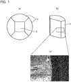
- FIG. 1 shows a photograph of a die used in the pressing in the first pressing step and second pressing step according to the present example.
- Fig. 1(a) is an plan view of a die including four parts
- Fig. 1(b) is a perspective view of one part when the die is separated
- Fig. 1(c) is a magnified photograph of a dotted line region of the part in the perspective view of Fig. 1(b) .
- One die is formed of four parts as shown in Fig. 1(a) , and can be separated into the four parts.
- Fig. 1(b) is a perspective view of one of the parts, and the inside of the part has an inner surface, which is brought into contact with the punching bars, laminate, ceramic powder, etc.
- the die used in the present example is a square carbon die of 90 mm ⁇ 90 mm in inner dimension, which normally presents difficulty to production of inorganic fiber-bonded ceramic shaped products, and has a damaged die surface. An uneven appearance, which was formed under the influence of gas generated by pyrolysis, is observed on the inner surface of the die.
- a method for setting the laminate on the carbon die will be described with reference to Fig. 2(a) .
- carbon sheets 6 were arranged on side surfaces of a carbon die 1 (carbon mold) with a lower punching bar 10 set thereon.
- a CC composite material spacer 5 of 5 mm in thickness was placed on the lower punching bar 10 set, a carbon sheet 6 of 0.2 mm in thickness was laid thereon, and an alumina powder 8 was packed by 120 g, and the surface was adjusted to be flat.
- a carbon sheet 6 was laid on the alumina powder 8, and a laminate 7 was placed.
- the gaps between the laminate 7 (80 mm ⁇ 80 mm) and the die 1 (90 mm ⁇ 90 mm) were filled with the alumina powder 8 by 30 g, furthermore, a carbon sheet 6 was laid on the laminate 7, and the alumina powder 8 was also packed thereon by 120 g, and the surface was adjusted to be flat.
- the laminate 7 is surrounded by the alumina powder 8.
- a carbon sheet 6 was laid on the alumina powder 8, a CC composite material spacer 5 was arranged thereon, and finally, an upper punching bar 4 was set.
- Fig. 2(a) shows the laminate set in the carbon die. It is to be noted that though the carbon sheets 6 are highlighted because Fig. 2(a) is a schematic diagram, it is extremely unusual that pyrolysis gas is released to the outside of the die from the gaps between the alumina powder 8 and the carbon sheets 6 because the carbon sheets 6 are 0.2 mm in thickness and further reduced in thickness by the application of pressure, with the alumina powder 8 closely attached on the surfaces of the carbon sheets 6.
- the pressing in the first pressing step was carried out at a temperature of 1400°C and a pressure of 40 MPa under an argon atmosphere. Subsequently, with the pressure maintained, the temperature was increased to 1750°C, and maintained for 1 hour to carry out the pressing in the second pressing step, thereby providing an inorganic fiber-bonded ceramic material according to Example 1.
- Example 2 a laminate was set in a carbon die in accordance with the same procedure as in Example 1, subjected to the pressing in the first pressing step at a temperature of 1400°C and a pressure of 40 MPa, and subsequently subjected to the pressing in the second pressing step by increasing the temperature to 1850°C with the pressure maintained and maintaining the temperature for 1 hour, thereby providing an inorganic fiber-bonded ceramic material according to Example 2.
- the other condition is the same as in Example 1.
- the alumina surrounding the laminate was able to be easily removed by lightly tapping corners of the alumina with a plastic hammer, because it was cracked at room temperature resulting from cooling after the second pressing step due to a difference in thermal expansion between the fiber-bonded ceramic material and the alumina, and the carbon sheets were sandwiched between the alumina powder and the laminate.
- Figs. 3(a) and 3(b) show photographs after the fluorescent penetrant inspections on the obtained inorganic fiber-bonded ceramic materials according to Examples 1 and 2.
- the inorganic fiber-bonded ceramic material according to Example 1 with the low molding temperature somewhat tends to have a smaller defective region (white region in the black and white photograph of Fig. 3 ) in the end part, while the detective region is small in each case.
- the white region in Fig. 3 indicates that there are voids at side surfaces of the inorganic fiber-bonded ceramic materials. These voids are believed to be produced because pyrolysis gas generated by pyrolysis reaction was excessively released to the outside of the die. The voids were confirmed, although described later, by observing side surfaces of the test pieces after the bending test under an electron microscope. It is to be noted that stripe patterns observed over the entire inorganic fiber-boned ceramic materials are weave patterns of the fibers, but not defects in the photographs after the fluorescent penetrant inspections.
- Fig. 4 shows results of four-point bending tests from end parts to central parts of the inorganic fiber-bonded ceramic materials.
- Examples 1 and 2 both maintained stable four-point bending strength from the end parts to the central parts.
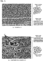
- the result is shown in Fig. 5 .
- the gaps between the fibers are filled with the surface layer of the raw fiber, and there is no void observed. It has been determined that even the end part is equivalent to the central part in both microstructure and mechanical properties in the case of the inorganic fiber-bonded ceramic materials according to Examples 1 and 2.
- a satin fabric of Tyranno Fiber (registered trademark: from Ube Industries, Ltd.) of 8.5 ⁇ m in fiber diameter was cut into squares of 180 mm ⁇ 180 mm, and a laminate was then prepared by stacking 500 sheets of stain fabric in the same way as in Example 1.
- As the carbon die a large-size square carbon die of 190 mm ⁇ 190 mm in inside dimension was used, which normally presents difficulty to preparation of inorganic fiber-bonded ceramic shaped products and has a damaged die surface.
- the alumina powder was put by 500 g under the laminate, by 80 g in the gaps between the laminate (180 mm ⁇ 180 mm) and the die (190 mm ⁇ 190 mm), and by 500 g on the laminate, because the gap volume was larger as compared with that in Example 1.
- the pressing in the first pressing step was carried out at a temperature of 1400°C and a pressure of 40 MPa under an argon atmosphere.
- the pressing in the second pressing step was carried out under the conditions of temperature: 1750°C and holding time: 2 hours to obtain an inorganic fiber-bonded ceramic material according to Example 3, which was larger than that in Example 1.
- a satin fabric of Tyranno Fiber (registered trademark: from Ube Industries, Ltd.) of 8.5 ⁇ m in fiber diameter was cut into squares of 89 mm ⁇ 89 mm, and then treated for 20 hours in air at 1000°C to obtain fabric sheets of coated inorganic fiber including an inorganic fiber part and a surface layer.
- a uniform surface layer having an average thickness of 510 nm, which corresponds to a 0.06, was formed on the surface of the coated inorganic fiber as in the examples.
- hot pressing was carried out with the use of a square carbon die of 90 mm ⁇ 90 mm in inside dimension, which normally presents difficulty to the preparation of inorganic fiber-bonded ceramic shaped products, and has a damaged die surface as in the case of Example 1.
- Fig. 2(b) shows the laminate set in the carbon die. Then, hot press molding was carried out under the conditions of pressure: 40 MPa, temperature: 1750°C, and holding time: 1 hour under an argon atmosphere as in the case of Example 1 to obtain an inorganic fiber-bonded ceramic material according to Comparative Example 1.
- Fig. 3 shows photographs after the fluorescent penetrant inspections on the obtained two types of inorganic fiber-bonded ceramic materials according to Comparative Examples 1 and 2.
- Figs. 3(c) and 3(d) respectively show the results of Comparative Examples 1 and 2.
- the (c) Comparative Example 1 with the molding temperature of 1750°C has a white region reaching the central part in the black and white photograph. This indicates that the surface has defects (cracks).
- the (d) Comparative Example 2 with the molding temperature of 1850°C has a slightly larger white region at the end, as compared with Comparative Example 1.
- Comparative Examples 1 and 2 both vary significantly in four-point bending strength from the end part to the central part, and for every point, all represent lower values as compared with the four-point bending strength in the examples.
- Fig. 5(b) shows the result of observing, under an electron microscope, a side surface of the four-point bending test piece collected from the end part. The end part of the inorganic fiber-bonded ceramic material has a large number of voids observed. This result well agrees with the result of the fluorescent penetrant inspection.
- the inorganic fiber-bonded ceramic material obtained by the method for producing an inorganic fiber-bonded ceramic material according to the present invention can be used under harsh environments at high temperature, including oxidizing atmospheres at 1000°C or higher in air, excellent in heat resistance, and high in both heat insulation property and mechanical properties.
Description
- The present invention relates to a method for producing an inorganic fiber-bonded ceramic material, which can produce, at a high yield, an inorganic fiber-bonded ceramic material with fewer defects, and with an end and a central part equivalent to each other in microstructure and mechanical properties, and also makes it possible to increase the ceramic material in size.
- In recent years, in aerospace fields and environmental and energy fields, highly reliable materials have been desired which are excellent in heat resistance and high in both heat insulation property and mechanical properties, in order to achieve higher efficiency and higher energy. Candidate materials therefor include inorganic fiber-bonded ceramic materials as an example. The inorganic fiber-bonded ceramic materials are insensitive to defects and high in fracture resistance, as compared with simple ceramics. In addition, the inorganic fiber-bonded ceramic materials are highly dense as compared with ceramic fiber-reinforced ceramic-matrix composites (CMC) produced by chemical vapor infiltration methods (CVI methods) or polymer infiltration and pyrolysis methods (PIP methods), and subjected to machining to provide high surface smoothness.
- Such an inorganic fiber-bonded ceramic material is disclosed in, for example,
Patent Literature 1. Briefly, the inorganic fiber-bonded ceramic material described inPatent Literature 1 is obtained by applying hot pressing under high temperature and pressure to a laminate of ceramic fibers containing, as their main constituent, Si-M-C-O (M represents Ti or Zr) covered with a surface layer containing SiO2 as its main constituent, and in the hot press process, some C in the Si-M-C-O fiber is produced on the fiber surface, and further, M in the Si-M-C-O fiber reacts with C to provide a structure including fine particles of MC dispersed in the inorganic substance. Accordingly, the structure of the inorganic fiber-bonded ceramic material is created in the hot press process under high temperature and pressure with the use of a pyrolysis reaction of the raw fiber. In other words, in order to obtain a favorable inorganic fiber-bonded ceramic structure, it is necessary to rigorously control the pyrolysis reaction in the hot pressing process. Further hot pressing processes with laminates comprising ceramic fibers are disclosed inPatent Literature Patent Literature 4 discloses a method for manufacturing laminated ceramic cutting tools including the step of pressing a laminate comprising a tape formed by ceramic whiskers or particles. Other methods involving pressing of ceramic objects in powder material are disclosed inPatent Literature 5 to 8. -
- Patent Literature 1:
JP 9-52776 A - Patent Literature 2:
CA 2 794 693 A1 - Patent Literature 3:
US 2004/029704 A1 - Patent Literature 4:
US 5 855 997 A - Patent Literature 5:
GB 2 200 317 A - Patent Literature 6:
GB 1 497 990 A - Patent Literature 7:
US 4 242 294 A - Patent Literature 8:
US 4 478 626 A - As described above, the inorganic fiber-bonded ceramic materials are excellent in heat resistance, and high in both heat insulation property and mechanical property, but have the following problems because of the need to rigorously control the pyrolysis reaction.
- (1) A carbon die for use in the hot press process produces, when used several times, a gap between surfaces for mating dies to reduce the dimensional accuracy of the gap between the dies, and increase the amount of pyrolysis gas emissions from the gap between the dies. Therefore, the end of a material close to the carbon die fails to have the original structure of the inorganic fiber-bonded ceramic material, and fails to achieve the high mechanical properties.
- (2) Unless the laminate of the coated inorganic fiber is molded to have accurate external dimensions, the end of a material close to the carbon die fails to have the original structure of the inorganic fiber-bonded ceramic material, and fails to achieve the high mechanical properties as in the case of the (1) mentioned above, and moreover, the mechanical properties are degraded over the entire material. Therefore, it is necessary to prepare a laminate with high dimensional accuracy, which requires much time.
- (3) When an attempt is made to increase the inorganic fiber-bonded ceramic material in size, the size of the laminate has to be increased, and the load put on punching bars and the carbon die is increased to more frequently cause sudden breakage of the die or upper or lower punching bars.
- (4) When an attempt is made to increase the inorganic fiber-bonded ceramic material in size, heterogeneity in structure will be produced due to a difference in the amount of pyrolysis gas emissions between an end of and a central part of the laminate.
- As just described, in order to produce, at a high yield and at a reduced cost, an inorganic fiber-bonded ceramic material which is stable in quality with an end and a central part equivalent to each other in microstructure and mechanical properties, while the pyrolysis in the hot press process is rigorously controlled, and in order to promote the increased size of the inorganic fiber-bonded ceramic material, the prior method for producing an inorganic fiber bonded ceramic is not able to be considered always sufficient.
- The present invention has been achieved in view of the problems mentioned above, and an object of the present invention is to provide a method for producing an inorganic fiber-bonded ceramic material, which can produce, at a high yield, an inorganic fiber-bonded ceramic material with fewer defects, and with an end and a central part equivalent to each other in microstructure and mechanical properties, and also makes it possible to increase the ceramic material in size.
- In order to achieve the object mentioned above, the inventors have found, as a result of earnest studies, that a ceramic powder is arranged around a laminate, and two-stage hot pressing is carried out such that the ceramic powder is brought into a hermetically sealed condition in advance to such an extent that the emission of pyrolysis gas from the inorganic fiber can be reduced in the first-stage pressing of the two-stage hot pressing to make the pyrolysis reaction of the inorganic fiber in the second-stage press process homogeneous throughout the entire shaped product, thereby making it possible to produce, at a high yield, an inorganic fiber-bonded ceramic material with fewer defects, and with an end and a central part equivalent to each other in microstructure and mechanical properties, and also making it possible to increase the ceramic material in size.
- More specifically, the present invention provides a method for producing an in organic fiber-bonded ceramic material, comprising: a first pressing step of setting a laminate in a carbon die so as to be surrounded on all sides by a ceramic powder, the laminate being obtained by stacking a shaped product of a coated inorganic fiber, the shaped product including an inorganic fiber part formed of inorganic fibers having a pyrolysis initiation temperature of 1900°C or lower and a surface layer formed of an inorganic substance for bonding the inorganic fibers to each other, and pressing the laminate at a temperature of 1000 to 1800°C and a pressure of 5 to 50 MPa in an inert gas atmosphere; and a second pressing step of pressing the ceramic coated laminate obtained in the first pressing step at a temperature of 1600 to 1900°C, which is higher than that in the first pressing step, and at a pressure of 5 to 100 MPa in an inert gas atmosphere to pyrolyze the inorganic fiber homogeneously throughout the entire shaped product, wherein the inorganic fiber part is formed of an inorganic substance containing: (a) an amorphous substance containing Si, M, C, and O (M represents Ti or Zr); (b) an aggregate of a crystalline ultrafine particle containing β-SiC, MC, and C and an amorphous substance containing SiO2 and MO2 (M is the same as in (a)); or (c) a mixture of the (a) amorphous substance and the (b) aggregate, and the surface layer includes an inorganic substance containing: (d) an amorphous substance containing Si, O, and possibly M (M represents Ti or Zr); (e) a crystalline substance containing crystalline SiO2 and/or MO2 (M is the same as in (d)); or (f) a mixture of the (d) amorphous substance and the (e) crystalline substance.
- In addition, in the method for producing an inorganic fiber-bonded ceramic material according to the present invention, the surface layer can be adapted to have a thickness T (µm) from T = aD in which a is a numerical value in a range of 0.023 to 0.090, and D denotes a fiber diameter (µm) of the coated inorganic fiber.
- In addition, in the method for producing an inorganic fiber-bonded ceramic material according to the present invention, the ceramic powder is either an alumina powder or a mixture of an inorganic substance, which melts at 1800°C or lower, and an inorganic substance having a higher melting temperature than the pressing temperature in the second pressing step, wherein the inorganic substance, which melts at 1800°C or lower, has glass containing SiO2 as its main constituent, and the inorganic substance having a higher melting temperature than the pressing temperature in the second pressing step is carbon or BN. Furthermore, an ambient pressure in the first pressing step and the second pressing step can range 0.01 to 1 MPa.
- As just described, according to the present invention, a method for producing an inorganic fiber-bonded ceramic material can be provided, which can produce, at a high yield, an inorganic fiber-bonded ceramic material with fewer defects, and with an end and a central part equivalent to each other in microstructure and mechanical properties, and also makes it possible to increase the ceramic material in size.
-
-
Fig. 1(a) is a top view of a die including four parts for use in the present examples,Fig. 1(b) is a perspective view of one part after the die is separated,Fig. 1(c) is a magnified photograph of a dotted line region ofFig. 1(b) , and these figures are a photograph showing a typical die with an inner surface damaged by the influence of gas generated by pyrolysis, and schematic diagrams indicating the location of the die photographed. -
Fig. 2(a) is a conceptual diagram showing arrangement of a laminate surrounded by a ceramic powder in a die, andFig. 2(b) is a conceptual diagram showing arrangement of a laminate in a die without the use of any ceramic powder. -
Fig. 3 shows photographs of visual observation results after fluorescent penetrant inspections for inorganic fiber-bonded ceramic materials obtained in Examples 1 and 2 and Comparative Examples 1 and 2. -
Fig. 4 is a diagram showing changes in four-point bending strength from ends to central parts of the inorganic fiber-bonded ceramic materials obtained in Examples 1 and 2 and Comparative Examples 1 and 2. -
Fig. 5 shows photographs of results of observing, under an electron microscope, side surfaces of test pieces after carrying out a bending test on the inorganic fiber-bonded ceramic materials obtained in Example 2 and Comparative Example 2. -
Fig. 6 is a diagram showing changes in four-point bending strength at an end and a central part of an inorganic fiber-bonded ceramic material obtained in Example 3. - A preferred embodiment of a method for producing an inorganic fiber-bonded ceramic material according to the present invention will be described in detail below.
- The method for producing an inorganic fiber-bonded ceramic material according to the present embodiment includes: a first pressing step of setting a laminate as a raw material in a carbon die so as to be surrounded on all sides with a ceramic powder, the laminate being obtained by stacking a shaped product of a coated inorganic powder, the shaped product including an inorganic fiber part formed of inorganic fibers having a pyrolysis initiation temperature of 1900°C or lower and a surface layer formed of an inorganic substance for bonding the inorganic fibers to each other, and pressing the laminate at a temperature of 1000 to 1800°C and a pressure of 5 to 50 MPa in an inert gas atmosphere; and a second pressing step of pressing the ceramic coated laminate obtained in the first pressing step at a temperature of 1600 to 1900°C, which is higher than that in the first pressing step, and at a pressure of 5 to 100 MPa in an inert gas atmosphere to pyrolyze the inorganic fiber homogeneously throughout the entire shaped product,
wherein the inorganic fiber part is formed of an inorganic substance containing: - (a) an amorphous substance containing Si, M, C, and O (M represents Ti or Zr);
- (b) an aggregate of a crystalline ultrafine particle containing β-SiC, MC, and C and an amorphous substance containing SiO2 and MO2 (M is the same as in (a)); or
- (c) a mixture of the (a) amorphous substance and the (b) aggregate, and
- (d) an amorphous substance containing Si, O, and possibly M (M represents Ti or Zr);
- (e) a crystalline substance containing crystalline SiO2 and/or MO2 (M is the same as in (d)); or
- (f) a mixture of the (d) amorphous substance and the (e) crystalline substance;
- In the present embodiment, the laminate as a raw material for the inorganic fiber-bonded ceramic material can be obtained by laminating a shaped product of a coated inorganic fiber including: an inorganic fiber part of inorganic fibers having a pyrolysis initiation temperature of 1900°C or lower; and a surface layer of an inorganic substance for bonding the inorganic fibers to each other. The shaped product of the coated inorganic fiber is not particularly limited in terms of form, but can be a continuous fiber, a chopped short fiber obtained by cutting a continuous fiber, or a sheet-like fiber or fabric obtained by unidirectionally stretching a continuous fiber.
- In the present embodiment, the shaped product of the coated inorganic fiber can be prepared by heating the following inorganic fiber to a temperature in the range of 500 to 1600°C under an oxidizing atmosphere in accordance with the method described in, for example,
JP 62-289641 A - The shaped product of the coated inorganic fiber includes the inner inorganic fiber part and the surface layer outside the inorganic fiber part. The inorganic fiber part is formed of an inorganic substance containing: (a) an amorphous substance containing Si, M, C and O (M represents Ti or Zr; the same shall apply hereafter); (b) an aggregate of a crystalline ultrafine particle containing β-SiC, MC and C, and an amorphous substance containing SiO2 and MO2; or (c) a mixture of the (a) amorphous substance and (b) aggregate mentioned above, whereas the surface layer is preferably formed of an inorganic substance containing: (d) an amorphous substance containing Si, O and possibly M; (e) a crystalline substance containing crystalline SiO2 and/or MO2; or (f) a mixture of the (d) amorphous substance and (e) crystalline substance mentioned above. The respective elements of the inorganic fiber constituting the inorganic fiber part preferably have typical proportions of Si: 30 to 60 mass%, M: 0.5 to 35 mass%, preferably 1 to 10 mass%, C: 25 to 40 mass%, and O: 0.01 to 30 mass%. The equivalent diameter of the coated inorganic fiber is not particularly limited, but preferably 5 to 20 µm. In addition, the surface layer of the coated inorganic fiber is preferably mainly formed of SiO2.
- Furthermore, varying the thickness of the surface layer of the coated inorganic fiber depending on the fiber diameter of the inorganic fiber part (the diameter of the inorganic fiber) makes it possible to further stabilize properties of the inorganic fiber-bonded ceramic material. When the fiber diameter is denoted by D µm, the thickness T µm of the surface layer preferably falls within the range of 0.023D to 0.090D. There is a tendency for the surface layer effect of suppressing pyrolysis of the inorganic fiber to be decreased as the thickness of the surface layer is smaller than 0.023D. On the other hand, as the thickness of the surface layer is larger than 0.090D, there is a tendency for the proportion of the inorganic fiber part of the coated inorganic fiber in the fiber-bonded ceramic material to be lowered to degrade properties at elevated temperature.
- The method for producing an inorganic fiber-bonded ceramic material according to the present embodiment includes: a first pressing step of setting the laminate obtained in the way described above in a carbon die so as to be surrounded with a ceramic powder, and pressing the laminate at a temperature of 1000 to 1800°C and a pressure of 5 to 50 MPa in an inert gas atmosphere; and a second pressing step of pressing the ceramic coated laminate obtained in the first step at a temperature of 1600 to 1900°C, which is higher than that in the first pressing step, and a pressure of 5 to 100 MPa in an inert gas atmosphere.
- In the present embodiment, when the ceramic powder placed around the laminate is brought into a hermetically sealed condition in advance to such an extent that the emission of pyrolysis gas from the inorganic fiber can be reduced in the first-stage first pressing step of two-stage hot pressing step, the pyrolysis reaction of the inorganic fiber in the second-stage second pressing step can be made homogeneous throughout the entire shaped product.
- There will be described below the ceramic powder surrounding the laminate which is a feature of the present embodiment. In the present embodiment, in order to obtain the structure of the inorganic fiber-bonded ceramic material, the ceramic powder is used in order to cover the laminate by heating at a temperature lower than the pressing temperature in the second pressing step to such an extent that the emission of pyrolysis gas from the inorganic fiber can be reduced in the first pressing step. Therefore, it is difficult to rigorously control gas in the shaped product just by simply covering with the ceramic powder, because the gas generated by pyrolysis reaction is emitted through voids within the ceramic powder. In order to rigorously control gas, there is a need for heating at a temperature lower than the pressing temperature in the second pressing step to provide a condition hermetically sealed to such an extent that the emission of pyrolysis gas can be reduced. The condition hermetically sealed to such an extent that the emission of pyrolysis gas can be reduced does not have to be a condition sealed to such an extent that the pyrolysis gas is completely blocked, but preferably a hermetically sealed condition that can maintain the composition for the structure of the inorganic fiber-bonded ceramic material. Properties of the inorganic fiber-bonded ceramic material such as yield and strength vary depending on the hermetically sealed condition, and the hermetically sealed condition may be thus managed depending on purposes and requests.
- The gas generated by pyrolysis needs to be appropriately released to the outside of the die in some cases. As long as the temperature can be controlled at which the ceramic powder is brought into a hermetically sealed condition, the release and suppression of the pyrolysis gas can be controlled. For example, where the composition of the inorganic fiber-bonded ceramic material is rigorously controlled at the stage of a raw fiber, the temperature at which the ceramic powder is brought into a hermetically sealed condition is lowered so that no pyrolysis gas is released to the outside of the die. Alternatively, where it is desirable to reversely increase the release of pyrolysis gas, the temperature is increased at which the ceramic powder is brought into a hermetically sealed condition. The release and suppression of the pyrolysis gas can be controlled by varying the type and composition of the ceramic powder and controlling the temperature at which the ceramic powder is brought into a hermetically sealed condition, depending on the situation of the pyrolysis reaction of the inorganic fiber.
- In one embodiment of the present invention, the ceramic powder is alumina powder sintered and brought into a hermetically sealed condition in the range of 1300 to 1500°C. The alumina powders are preferred for use, because the powders are relatively inexpensive, easily available, and excellent in stability at elevated temperature.
- In an alternative embodiment, the ceramic powder is a mixture of an inorganic substance which melts at 1800°C or lower and an inorganic substance which has a higher melting temperature than the pressing temperature of the second pressing step.
In particular, a combination of glass containing SiO2 as its main constituent as the inorganic substance melted at 1800°C or lower, and BN as the inorganic substance which has a higher melting temperature than the pressing temperature of the second pressing step is used. The use of the mixture of the glass containing SiO2 at its main constituent and the BN powder hermetically seals voids within the BN powder with the softened or melted SiO2 to cover the laminate with the densified ceramic material which can suppress pyrolysis gas emission in the range of 1300 to 1500°C, thereby making it possible to control the pyrolysis gas. - As just described, one of the points in the present embodiment is that the laminate surrounded with the ceramic powder in the first pressing step is heated at a temperature equal to or lower than the pressing temperature of the second pressing step to bring the periphery of the laminate into a hermetically sealed condition with the ceramic material to such an extent that the emission of pyrolysis gas can be suppressed. This can solve the following three problems.
- The first problem is the lifetime of the carbon die. As described above, typically, the inorganic fiber-bonded ceramic material achieves its fine and complex structure by controlling pyrolysis of the raw fiber in the process of hot pressing. In the process of hot pressing, the composition in the raw fiber is controlled while releasing gas (SiO, CO, etc.) derived from the elements constituting the fiber, which is generated by pyrolysis reaction, through the gap between the dies to the outside. In this case, the reaction of the carbon die with the released gas produces a carbide or oxide containing Si as its main constituent on the surface of the carbon die. Therefore, when the carbon die is used several times, the produced carbide or the like will be deposited to produce a gap between mating surfaces of the dies. Furthermore, when an attempt is made to remove the carbide or the like, a portion of the carbon die will be chipped off along with the carbide or the like, and a gap will be likewise produced between the mating surfaces of the dies. Thus, the dimensional accuracy of the gap between the dies is reduced to increase the amount of pyrolysis gas emissions from the gap between the dies, and an end part of the ceramic material near the carbon die fails to have the normal structure of the inorganic fiber-bonded ceramic material, thereby failing to achieve any high mechanical properties. Moreover, the reduced dimensional accuracy may deteriorate the mechanical properties of the entire material in some cases. Thus, there is a need for the carbon die to be frequently exchanged, though the frequency of exchange varies depending on the hot pressing condition. Therefore, there is a need to reduce the cost of the die because the die is costly.
- The second problem is that even if the dimensional accuracy of the die is kept constant, unless the laminate of the coated inorganic fiber is shaped with accuracy of external dimensions, the variation in gap between the dice and the laminate like the first problem leads to an unequal amount of pyrolysis gas emissions, resulting in failure to rigorously control the pyrolysis reaction. However, the coated inorganic fiber varies in cutting dimension because of its significantly poor workability, and when this variation is increased, an end part of the material near the carbon die fails to have the normal structure of the inorganic fiber-bonded ceramic material, thereby failing to achieve any high mechanical properties. Moreover, the reduced dimensional accuracy may deteriorate the mechanical properties of the entire material in some cases. Therefore, there is a need to prepare a laminate with a high degree of dimensional accuracy, which requires time.
- Moreover, as the third problem, structure heterogeneity is listed which is caused by the difference in the amount of pyrolysis gas emissions between an end part and a central part of the laminate, with the increase in size of inorganic fiber-bonded ceramic material. As also mentioned in association with the first problem, the inorganic fiber-bonded ceramic material achieves its fine microstructure by controlling the composition in the raw fiber while releasing gas (SiO, CO, etc.) derived from the elements constituting the fiber, which is generated by pyrolysis reaction in the process of the hot pressing process, through the gap between the dies. Therefore, when the inorganic fiber-bonded ceramic material undergoes an increase in size, structure heterogeneity is produced between the end part and central part of the shaped product, due to the difference in holding time at the target temperature, as well as ease of releasing pyrolysis gas, etc. For example, when the molding temperature and the holding time are respectively set to 1800°C and 1 hour, the end part of the shaped product reaches the target temperature earlier as compared with the central part thereof. In some cases, a difference in temperature may be produced between the end part and the central part. In such a case, the amount and timing of pyrolysis gas generation vary depending on differences in molding temperature and holding time between the end part and the central part. In order to increase the size of the shaped inorganic fiber-bonded ceramic material, there is a need to equalize the amounts of pyrolysis gas generation and release between the end part and central part of the shaped product.
- According to the present embodiment, the ceramic powder is brought in advance into a condition hermetically sealed to such an extent that the emission of pyrolysis gas from the inorganic fiber can be reduced in the first pressing step to equalize pyrolysis reaction of the inorganic fiber in the second pressing step through the entire shaped product. As a result, it is possible to solve the three problems mentioned above, to produce, at a high yield, an inorganic fiber-bonded ceramic material with fewer defects, and with an end and a central part equivalent to each other in microstructure and mechanical properties, and also to increase the ceramic material in size.
- Furthermore, the ceramic powder is preferably a flowable powder. This powder can solve even the fourth problem at the same time.
- The fourth problem is sudden breakage of the die or upper and lower punching bars. It is extremely difficult to equalize the fiber volume fraction as the volume percentage of the fiber per unit volume in the raw fiber laminate before the hot pressing, and the laminate is partially sparse or dense. For this reason, in the application of pressure in the hot pressing, a non-uniform load is put on the laminate. Then, a load larger than expected one will be put on a section of the laminate which is higher in fiber volume fraction, as compared with a section of the laminate which is lower in fiber volume fraction. This non-uniform load may suddenly break the carbon die. Moreover, the shock may be also propagated to the upper and lower punching bars made of carbon to break the punching bars. These types of sudden breakage of the die and punching bars may cause damage to a heater of and an insulator of the hot pressing device in some cases. Furthermore, this sudden breakage is expected to occur with further increased frequency as the size of the laminate and the load put on the punching bars and the carbon die are increased. It is effective to sandwich a high-toughness ceramic composite material or a carbon fiber-reinforced carbon composite (CC composite) between the laminate and the die in order to prevent the sudden breakage of the die and the propagation of the shock to the upper and lower punching bars, but this is not a fundamental solution in itself. In order to increase the size of the shaped inorganic fiber-bonded ceramic material in the future, there is a need to prevent the sudden damage.
- In the present embodiment, because the use of the flowable powder as the ceramic powder can reduce the sparsity or density of the laminate in fiber volume fraction, the uneven application of pressure is resolved in the hot pressing, and the partially concentrated load can be prevented from suddenly breaking the carbon die. In order to increase the flowability of the ceramic powder, it is also effective to, for example, make particles of the powder spherical with the use of a spray dryer or the like and use the powder of the spherical particles.
- Next, the pressing in the first pressing step and second pressing step will be specifically described. First, the laminate is put into a carbon die for use in pressing so as to be covered with the ceramic powder, with punching bars for pressing set thereon, and put into a pressing device. In this case, the carbon die may be sprayed with BN in order to improve the mold release property between the carbon die and the ceramic powder. In addition, sandwiching a carbon sheet between the carbon die and the ceramic powder is also an effective measure for improving the mold release property. Likewise, as for the mold release property between the ceramic powder and the laminate, sandwiching a carbon sheet between the ceramic powder and the laminate can facilitate the removal of the shaped product of the inorganic fiber-bonded ceramic material after hot press molding.
- After setting the die in the hot pressing device, the atmosphere is substituted with an inert atmosphere. Then, the laminate is covered with a ceramic material of the densified ceramic powder, and the temperature is increased up to the temperature set in the first pressing step in the range of 1000 to 1800°C to provide a condition hermetically sealed to such an extent that the emission of pyrolysis gas from the laminate is suppressed. The rate of temperature increase in this case is not particularly specified, but a rate of temperature increase is preferred which results in a small difference in temperature between the periphery and central part of the laminate. In addition, in order to equalize the temperature at the periphery and central part of the laminate, a period of time for maintaining a temperature may be set before the pressing at a temperature equal to or lower than the pressing temperature in the first pressing step. Then, a pressure load of 5 to 50 MPa is applied at the pressing temperature in the first pressing step. This pressing may be carried out with the temperature maintained, or while rising the temperature. After the pressing in the first pressing step, in succession, the temperature can be increased up to a predetermined temperature in the range of 1600 to 1900°C, which is higher than the pressing temperature in the first pressing step, and a pressure load of 5 to 100 MPa can be applied to perform the pressing in the second pressing step. The rate of temperature increase from the first pressing step to the second pressing step is desirably a rate of temperature increase, which results in a small difference in temperature between the periphery and central part of the laminate as in the case of the first pressing step, and a period of time for maintaining a temperature may be set in order to equalize the temperature at the periphery and central part of the laminate.
- The pressing in the first pressing step and the pressing in the second pressing step may be carried out at an interval, or carried out continuously. However, where after completing the pressing in the first step, once the temperature is lowered, the ceramic material in the hermetically sealed condition may be cracked to release, from the crack, pyrolysis gas from the inorganic fiber in some cases before increasing the temperature up to the pressing temperature in the second pressing step. In addition, also from the perspective of making the pressing steps more efficient, the pressing in the first pressing step and the pressing in the second pressing step may be preferably carried out continuously.
- The atmospheres in the first pressing step and second pressing step are an inert gas atmosphere, typically, preferably an argon gas atmosphere. In addition, it is also effective to increase the atmosphere pressures, as a method for increasing the effect when the ceramic powder is sintered to control the gas generated by pyrolysis. The increased atmosphere pressure in the hot pressing device has the effect of reducing the emission of the gas generated by pyrolysis reaction. In addition, the increase in atmosphere pressure is an effective measure for preventing the emission of pyrolysis gas due to variation in the hermetically sealed condition of the ceramic powder. The atmosphere pressure increased from the start of the temperature increase can also inhibit pyrolysis before the ceramic powder is sintered. The atmosphere pressure typically falls within the range of 0.01 to 1 MPa, in particular, the range of 0.1 to 1 MPa preferably. However, in order to keep voids from being involved in the inorganic fiber-bonded ceramic material, the atmosphere pressure needs to be equal to or lower than the pressing pressure.
- The present invention will be described below with reference to examples and comparative examples. First, examinations and characteristic evaluations were carried out on inorganic fiber-bonded ceramic materials according to the examples and comparative examples as follows.
- Fluorescent penetrant inspections for use in inspection of precision machinery components were carried out in order to examine surface defect states at ends and central parts of the inorganic fiber-bonded ceramic materials molded. Here is the method for the fluorescent penetrant inspections. First, the surfaces of the shaped inorganic fiber-bonded ceramic materials were subjected to grinding to remove a thickness of about 0.5 to 1 mm by means of a surface grinder, then cleaned with ethanol to wash out contaminations, etc. such as adherent matters and oil and fats which disturb penetration of penetrants, and dried at 70°C. Next, a penetrant (Super Glow fluorescent penetrant agents, OD-2800 III) was applied by brush coating, left as it was for about 10 minutes, and lightly washed with running water, and a minute amount of developer (Super Glow, DN-600P) was sprayed. Then, after leaving out for about 5 minutes, an ultraviolet irradiator with a degree of ultraviolet intensity (800 µW/cm2 or more) capable of clearly identifying a specified pattern was used to immediately conduct ultraviolet irradiation with a wavelength of 330 to 360 nm in a dark place, and the surfaces were visually observed, and photographed.
- From the inorganic fiber-bonded ceramic material subjected to the second pressing step, four-point bending test pieces of 4 mm in width, 3 mm in height, and 40 mm in length were collected, and subjected to a four-point bending test at a distance of 10 mm between upper supports, a distance of 30 mm between lower supports, and a crosshead speed of 0.5 mm/min with the use of a material tester to measure the bending strength from an end to a central part for the shaped inorganic fiber-bonded ceramic materials.
- A satin fabric was prepared using Tyranno Fiber (registered trademark: from Ube Industries, Ltd.) of 8.5 µm in fiber diameter as the inorganic fiber, cut into squares of 80 mm × 80 mm, and retained for 20 hours in air at 1000°C to obtain fabric sheets of coated inorganic fiber including an inorganic fiber part and a surface layer. A uniform surface layer having an average thickness of 510 nm, which corresponds to a = 0.06, was formed on the surface of the coated inorganic fiber. The symbol "a" herein refers to a = T/D when the thickness of the surface layer of the coated inorganic fiber and the diameter of the inorganic fiber thereof are respectively denoted by T µm and D µm. Then, 100 sheets of satin fabric were stacked to prepare a laminate in which the sheets are fixed with an organic binder. The inorganic fiber part of the coated inorganic fiber in the laminate was composed of a mixture of: an amorphous substance containing mainly Si, Ti, C and 0; and an aggregate of crystalline ultrafine particles containing β-SiC, TiC and C, and an amorphous substance containing SiO2 and TiO2, whereas the surface layer was mainly composed of an amorphous substance containing Si, O and Ti.
- Next, the prepared laminate was set in a carbon die.
-
FIG. 1 shows a photograph of a die used in the pressing in the first pressing step and second pressing step according to the present example.Fig. 1(a) is an plan view of a die including four parts,Fig. 1(b) is a perspective view of one part when the die is separated, andFig. 1(c) is a magnified photograph of a dotted line region of the part in the perspective view ofFig. 1(b) . One die is formed of four parts as shown inFig. 1(a) , and can be separated into the four parts.Fig. 1(b) is a perspective view of one of the parts, and the inside of the part has an inner surface, which is brought into contact with the punching bars, laminate, ceramic powder, etc. when used for the pressing, and is damaged by the influence of gas generated by pyrolysis. A typical example of the damaged die is shown inFig. 1(c) . The die used in the present example is a square carbon die of 90 mm × 90 mm in inner dimension, which normally presents difficulty to production of inorganic fiber-bonded ceramic shaped products, and has a damaged die surface. An uneven appearance, which was formed under the influence of gas generated by pyrolysis, is observed on the inner surface of the die. - A method for setting the laminate on the carbon die will be described with reference to
Fig. 2(a) . First,carbon sheets 6 were arranged on side surfaces of a carbon die 1 (carbon mold) with alower punching bar 10 set thereon. Next, a CCcomposite material spacer 5 of 5 mm in thickness was placed on thelower punching bar 10 set, acarbon sheet 6 of 0.2 mm in thickness was laid thereon, and analumina powder 8 was packed by 120 g, and the surface was adjusted to be flat. Then, acarbon sheet 6 was laid on thealumina powder 8, and alaminate 7 was placed. Next, the gaps between the laminate 7 (80 mm × 80 mm) and the die 1 (90 mm × 90 mm) were filled with thealumina powder 8 by 30 g, furthermore, acarbon sheet 6 was laid on thelaminate 7, and thealumina powder 8 was also packed thereon by 120 g, and the surface was adjusted to be flat. Thus, thelaminate 7 is surrounded by thealumina powder 8. Thereafter, acarbon sheet 6 was laid on thealumina powder 8, a CCcomposite material spacer 5 was arranged thereon, and finally, anupper punching bar 4 was set. -
Fig. 2(a) shows the laminate set in the carbon die. It is to be noted that though thecarbon sheets 6 are highlighted becauseFig. 2(a) is a schematic diagram, it is extremely unusual that pyrolysis gas is released to the outside of the die from the gaps between thealumina powder 8 and thecarbon sheets 6 because thecarbon sheets 6 are 0.2 mm in thickness and further reduced in thickness by the application of pressure, with thealumina powder 8 closely attached on the surfaces of thecarbon sheets 6. In this condition, the pressing in the first pressing step was carried out at a temperature of 1400°C and a pressure of 40 MPa under an argon atmosphere. Subsequently, with the pressure maintained, the temperature was increased to 1750°C, and maintained for 1 hour to carry out the pressing in the second pressing step, thereby providing an inorganic fiber-bonded ceramic material according to Example 1. - Next, a laminate was set in a carbon die in accordance with the same procedure as in Example 1, subjected to the pressing in the first pressing step at a temperature of 1400°C and a pressure of 40 MPa, and subsequently subjected to the pressing in the second pressing step by increasing the temperature to 1850°C with the pressure maintained and maintaining the temperature for 1 hour, thereby providing an inorganic fiber-bonded ceramic material according to Example 2. The other condition is the same as in Example 1. The alumina surrounding the laminate was able to be easily removed by lightly tapping corners of the alumina with a plastic hammer, because it was cracked at room temperature resulting from cooling after the second pressing step due to a difference in thermal expansion between the fiber-bonded ceramic material and the alumina, and the carbon sheets were sandwiched between the alumina powder and the laminate.
-
Figs. 3(a) and 3(b) show photographs after the fluorescent penetrant inspections on the obtained inorganic fiber-bonded ceramic materials according to Examples 1 and 2. - In comparison between the two inorganic fiber bonded ceramic materials, the inorganic fiber-bonded ceramic material according to Example 1 with the low molding temperature somewhat tends to have a smaller defective region (white region in the black and white photograph of
Fig. 3 ) in the end part, while the detective region is small in each case. The white region inFig. 3 indicates that there are voids at side surfaces of the inorganic fiber-bonded ceramic materials. These voids are believed to be produced because pyrolysis gas generated by pyrolysis reaction was excessively released to the outside of the die. The voids were confirmed, although described later, by observing side surfaces of the test pieces after the bending test under an electron microscope. It is to be noted that stripe patterns observed over the entire inorganic fiber-boned ceramic materials are weave patterns of the fibers, but not defects in the photographs after the fluorescent penetrant inspections. - Next,
Fig. 4 shows results of four-point bending tests from end parts to central parts of the inorganic fiber-bonded ceramic materials. In spite of the use of the damaged die, Examples 1 and 2 both maintained stable four-point bending strength from the end parts to the central parts. In addition, a side surface of the four-point bending test piece, which was collected from the end part, was observed with an electron microscope. The result is shown inFig. 5 . The gaps between the fibers are filled with the surface layer of the raw fiber, and there is no void observed. It has been determined that even the end part is equivalent to the central part in both microstructure and mechanical properties in the case of the inorganic fiber-bonded ceramic materials according to Examples 1 and 2. This result has demonstrated that the die which has been ever disposed of can be used, and determined that the lifetime of the die can be extended. Furthermore, the use of the laminate (80 mm × 80 mm) which was 10 mm smaller with respect to the dimensions (90 mm × 90 mm) of the die has succeeded in the previously described results in spite of the extremely large clearance between the die and the laminate. - A satin fabric of Tyranno Fiber (registered trademark: from Ube Industries, Ltd.) of 8.5 µm in fiber diameter was cut into squares of 180 mm × 180 mm, and a laminate was then prepared by stacking 500 sheets of stain fabric in the same way as in Example 1. As the carbon die, a large-size square carbon die of 190 mm × 190 mm in inside dimension was used, which normally presents difficulty to preparation of inorganic fiber-bonded ceramic shaped products and has a damaged die surface. Though the laminate was set in the carbon die in the same manner as in Example 1, the alumina powder was put by 500 g under the laminate, by 80 g in the gaps between the laminate (180 mm × 180 mm) and the die (190 mm × 190 mm), and by 500 g on the laminate, because the gap volume was larger as compared with that in Example 1. In this condition, the pressing in the first pressing step was carried out at a temperature of 1400°C and a pressure of 40 MPa under an argon atmosphere. Subsequently, with the pressure maintained, the pressing in the second pressing step was carried out under the conditions of temperature: 1750°C and holding time: 2 hours to obtain an inorganic fiber-bonded ceramic material according to Example 3, which was larger than that in Example 1.
- From each of an end part and a central part of the 180 mm × 180 mm surface of the obtained inorganic fiber-bonded ceramic material of 180 mm × 180 mm surface and about 60 mm thickness according to Example 3, fifteen bending test pieces were collected in the thickness direction to measure the four-point bending strength of the end part and central part. The measurement results are shown in
Fig. 6 . In spite of the use of the damaged die, and of the large size as compared with that in Example 1, there is no variation in strength between the end part and central part of the inorganic fiber-bonded ceramic material according to Example 3. This result has demonstrated that the die which has been ever disposed of can be used, and it has been found that the lifetime of the die can be extended. In addition, the use of the laminate (180 mm × 180 mm) which was 10 mm smaller with respect to the dimensions (190 mm × 190 mm) of the die has succeeded in the previously described results in spite of the extremely large clearance between the die and the laminate. Moreover, in spite of being larger in form with the sparser or denser laminate as compared with Example 1, this example has succeeded in molding the inorganic fiber-bonded ceramic material, without sudden breakage of the die, etc., or without any variation in strength between the central part and the end part. - A satin fabric of Tyranno Fiber (registered trademark: from Ube Industries, Ltd.) of 8.5 µm in fiber diameter was cut into squares of 89 mm × 89 mm, and then treated for 20 hours in air at 1000°C to obtain fabric sheets of coated inorganic fiber including an inorganic fiber part and a surface layer. A uniform surface layer having an average thickness of 510 nm, which corresponds to a = 0.06, was formed on the surface of the coated inorganic fiber as in the examples. Next, hot pressing was carried out with the use of a square carbon die of 90 mm × 90 mm in inside dimension, which normally presents difficulty to the preparation of inorganic fiber-bonded ceramic shaped products, and has a damaged die surface as in the case of Example 1. The method for setting the laminate in the die will be described with reference to
Fig. 2(b) . First,carbon sheets 6 were arranged on side surfaces of a carbon die 1 (carbon mold) with alower punching bar 10 set. Next, a CCcomposite material spacer 5 of 5 mm in thickness was placed on thelower punching bar 10 set, acarbon sheet 6 of 0.2 mm in thickness was laid thereon, and alaminate 7 was placed thereon. Thelaminate 7 was composed of 100 sheets of fabric stacked and fixed with an organic binder. Then, acarbon sheet 6 was laid thereon, furthermore, a CCcomposite material spacer 5 was placed on thecarbon sheet 6, and finally, anupper punching bar 4 was set.Fig. 2(b) shows the laminate set in the carbon die. Then, hot press molding was carried out under the conditions of pressure: 40 MPa, temperature: 1750°C, and holding time: 1 hour under an argon atmosphere as in the case of Example 1 to obtain an inorganic fiber-bonded ceramic material according to Comparative Example 1. - Next, a laminate was set in a carbon die in accordance with the same procedure as in Comparative Example 1, and subjected to hot press molding at a temperature of 1850°C to obtain an inorganic fiber-bonded ceramic material according to Comparative Example 2. The other condition is the same as in Comparative Example 1.
-
Fig. 3 shows photographs after the fluorescent penetrant inspections on the obtained two types of inorganic fiber-bonded ceramic materials according to Comparative Examples 1 and 2.Figs. 3(c) and 3(d) respectively show the results of Comparative Examples 1 and 2. The (c) Comparative Example 1 with the molding temperature of 1750°C has a white region reaching the central part in the black and white photograph. This indicates that the surface has defects (cracks). Moreover, the (d) Comparative Example 2 with the molding temperature of 1850°C has a slightly larger white region at the end, as compared with Comparative Example 1. This indicates that the end part has a large number of defects (voids located from the side surface toward the central part of the inorganic fiber-bonded ceramic material), and the area of the defects is extended with the increase in molding temperature. When both the inorganic fiber-bonded ceramic materials in obtained Comparative Examples 1 and 2 are compared with the inorganic fiber-bonded ceramic materials obtained in Examples 1 and 2, Comparative Example 1 has cracks, and Comparative Example 2 has defects (voids) extended toward the surface at the end. Next,Fig. 4 shows results of four-point bending tests from end parts to central parts of the inorganic fiber-bonded ceramic materials according to Comparative Examples 1 and 2. Because of the use of the damaged die, Comparative Examples 1 and 2 both vary significantly in four-point bending strength from the end part to the central part, and for every point, all represent lower values as compared with the four-point bending strength in the examples. In addition,Fig. 5(b) shows the result of observing, under an electron microscope, a side surface of the four-point bending test piece collected from the end part. The end part of the inorganic fiber-bonded ceramic material has a large number of voids observed. This result well agrees with the result of the fluorescent penetrant inspection. - From the foregoing, it is determined that according to the present invention, even the use of a damaged die with poor dimensional accuracy, which ever has difficulty with control of gas generated by pyrolysis in the hot press process, can achieve a dense inorganic fiber-bonded ceramic material without any voids even at an end part, which maintains a high mechanical properties from a central part to the end part.
- The inorganic fiber-bonded ceramic material obtained by the method for producing an inorganic fiber-bonded ceramic material according to the present invention can be used under harsh environments at high temperature, including oxidizing atmospheres at 1000°C or higher in air, excellent in heat resistance, and high in both heat insulation property and mechanical properties.
-
- 1
- carbon die (parts)
- 3
- position for setting laminate
- 4
- upper punching bar
- 5
- CC composite spacer
- 6
- carbon sheet
- 7
- laminate
- 8
- alumina powder
- 9
- CC composite mold
- 10
- lower punching bar
- 12
- void
Claims (3)
- A method for producing an inorganic fiber-bonded ceramic material, comprising:a first pressing step of setting a laminate in a carbon die so as to be surrounded on all sides by a ceramic powder, the laminate being obtained by stacking a coated shaped product of a coated inorganic fiber, the shaped product including an inorganic fiber part formed of inorganic fibers having a pyrolysis initiation temperature of 1900°C or lower and a surface layer formed of an inorganic substance for bonding the inorganic fibers to each other, and pressing the laminate at a temperature of 1000 to 1800°C and a pressure of 5 to 50 MPa in an inert gas atmosphere; anda second pressing step of pressing the ceramic coated laminate obtained in the first pressing step at a temperature of 1600 to 1900°C, which is higher than that in the first pressing step, and at a pressure of 5 to 100 MPa in an inert gas atmosphere to pyrolyze the inorganic fiber homogeneously throughout the entire shaped product,wherein the inorganic fiber part is formed of an inorganic substance containing:(a) an amorphous substance containing Si, M, C, and O (M represents Ti or Zr);(b) an aggregate of a crystalline ultrafine particle containing β-SiC, MC, and C and an amorphous substance containing SiO2 and MO2 (M is the same as in (a)); or(c) a mixture of the (a) amorphous substance and the (b) aggregate, andthe surface layer is formed of an inorganic substance containing:(d) an amorphous substance containing Si, O, and possibly M (M represents Ti or Zr);(e) a crystalline substance containing crystalline SiO2 and/or MO2 (M is the same as in (d)); or(f) a mixture of the (d) amorphous substance and the (e) crystalline substance:wherein the ceramic powder is an alumina powder, orwherein the ceramic powder includes a mixture of an inorganic substance which melts at 1800°C or lower and an inorganic substance having a higher melting temperature than the pressing temperature in the second pressing step, and the inorganic substance which melts at 1800°C or lower is glass containing SiO2 as its main constituent, and the inorganic substance having a higher melting temperature than the pressing temperature in the second pressing step is carbon or BN.
- The method for producing an inorganic fiber-bonded ceramic material according to claim 1, wherein the surface layer has a thickness T (µm) from T = aD in which a is a numerical value in a range of 0.023 to 0.090, and D denotes a fiber diameter (µm) of the inorganic fiber part.
- The method for producing an Inorganic fiber-bonded ceramic material according to claim 1, wherein an ambient pressure in the first pressing step and the second pressing step ranges from 0.01 to 1 MPa,
Applications Claiming Priority (2)
| Application Number | Priority Date | Filing Date | Title |
|---|---|---|---|
| JP2012075315 | 2012-03-29 | ||
| PCT/JP2013/058016 WO2013146514A1 (en) | 2012-03-29 | 2013-03-21 | Process for producing inorganic-fiber-bonded ceramic material |
Publications (3)
| Publication Number | Publication Date |
|---|---|
| EP2832709A1 EP2832709A1 (en) | 2015-02-04 |
| EP2832709A4 EP2832709A4 (en) | 2015-03-25 |
| EP2832709B1 true EP2832709B1 (en) | 2019-05-08 |
Family
ID=49259771
Family Applications (1)
| Application Number | Title | Priority Date | Filing Date |
|---|---|---|---|
| EP13768590.5A Active EP2832709B1 (en) | 2012-03-29 | 2013-03-21 | Process for producing inorganic-fiber-bonded ceramic material |
Country Status (4)
| Country | Link |
|---|---|
| US (1) | US9701587B2 (en) |
| EP (1) | EP2832709B1 (en) |
| JP (1) | JP5910728B2 (en) |
| WO (1) | WO2013146514A1 (en) |
Families Citing this family (2)
| Publication number | Priority date | Publication date | Assignee | Title |
|---|---|---|---|---|
| US10753884B2 (en) | 2016-06-14 | 2020-08-25 | Rolls-Royce Corporation | Nondestructive inspection of composite materials |
| CN107234551A (en) * | 2017-06-30 | 2017-10-10 | 福建瑞祺新材料有限公司 | A kind of high-temperature-resistant high cube nitrification borax wheel ceramic combination agent and preparation method thereof |
Citations (5)
| Publication number | Priority date | Publication date | Assignee | Title |
|---|---|---|---|---|
| GB1497990A (en) * | 1975-11-10 | 1978-01-12 | Tokyo Shibaura Electric Co | Composite ceramic articles and a method of manufacturing the same |
| US4242294A (en) * | 1977-08-18 | 1980-12-30 | Motoren- Und Turbinen-Union Munchen Gmbh | Method for encapsulating a molded ceramic member |
| US4478626A (en) * | 1981-09-01 | 1984-10-23 | Kabushiki Kaisha Kobe Seiko Sho | Method of hot isostatic pressing treatment |
| GB2200317A (en) * | 1987-01-27 | 1988-08-03 | Ae Plc | Isostatic moulding |
| US5855997A (en) * | 1996-02-14 | 1999-01-05 | The Penn State Research Foundation | Laminated ceramic cutting tool |
Family Cites Families (11)
| Publication number | Priority date | Publication date | Assignee | Title |
|---|---|---|---|---|
| US4428906A (en) * | 1982-04-28 | 1984-01-31 | Kelsey-Hayes Company | Pressure transmitting medium and method for utilizing same to densify material |
| JPS616180A (en) * | 1984-06-16 | 1986-01-11 | 工業技術院長 | Thermal hydrostatic pressure treatment for ceramic |
| JPH0819592B2 (en) | 1986-06-06 | 1996-02-28 | 旭化成工業株式会社 | Interlining |
| US5348694A (en) * | 1988-12-20 | 1994-09-20 | Superior Graphite Co. | Method for electroconsolidation of a preformed particulate workpiece |
| JP2579854B2 (en) | 1991-08-14 | 1997-02-12 | 宇部興産株式会社 | Inorganic fiber sintered body and method for producing the same |
| JP2792595B2 (en) * | 1993-09-03 | 1998-09-03 | 宇部興産株式会社 | Inorganic fiber sintered body and method for producing the same |
| JP3134729B2 (en) | 1995-08-17 | 2001-02-13 | 宇部興産株式会社 | Fiber-bonded ceramics and manufacturing method thereof |
| JP3739853B2 (en) | 1996-04-16 | 2006-01-25 | 松下電器産業株式会社 | Manufacturing method of ceramic sintered body |
| JP4239684B2 (en) | 2002-08-09 | 2009-03-18 | 宇部興産株式会社 | High heat resistant inorganic fiber bonded ceramic member and method for manufacturing the same |
| JP4426245B2 (en) * | 2003-10-07 | 2010-03-03 | 中部電力株式会社 | Method for producing metal oxide sintered body, and metal oxide sintered body |
| WO2011122219A1 (en) * | 2010-03-31 | 2011-10-06 | 宇部興産株式会社 | CERAMIC MATERIAL COATED WITH SiC AND HAVING SiC FIBERS BOUND THERETO |
-
2013
- 2013-03-21 WO PCT/JP2013/058016 patent/WO2013146514A1/en active Application Filing
- 2013-03-21 US US14/387,713 patent/US9701587B2/en active Active
- 2013-03-21 EP EP13768590.5A patent/EP2832709B1/en active Active
- 2013-03-21 JP JP2014507775A patent/JP5910728B2/en active Active
Patent Citations (5)
| Publication number | Priority date | Publication date | Assignee | Title |
|---|---|---|---|---|
| GB1497990A (en) * | 1975-11-10 | 1978-01-12 | Tokyo Shibaura Electric Co | Composite ceramic articles and a method of manufacturing the same |
| US4242294A (en) * | 1977-08-18 | 1980-12-30 | Motoren- Und Turbinen-Union Munchen Gmbh | Method for encapsulating a molded ceramic member |
| US4478626A (en) * | 1981-09-01 | 1984-10-23 | Kabushiki Kaisha Kobe Seiko Sho | Method of hot isostatic pressing treatment |
| GB2200317A (en) * | 1987-01-27 | 1988-08-03 | Ae Plc | Isostatic moulding |
| US5855997A (en) * | 1996-02-14 | 1999-01-05 | The Penn State Research Foundation | Laminated ceramic cutting tool |
Non-Patent Citations (1)
| Title |
|---|
| ANONYMOUS: "Hot pressing - Wikipedia", 9 August 2016 (2016-08-09), XP055314308, Retrieved from the Internet <URL:https://en.wikipedia.org/wiki/Hot_pressing> [retrieved on 20161026] * |
Also Published As
| Publication number | Publication date |
|---|---|
| EP2832709A4 (en) | 2015-03-25 |
| JP5910728B2 (en) | 2016-04-27 |
| JPWO2013146514A1 (en) | 2015-12-14 |
| EP2832709A1 (en) | 2015-02-04 |
| US9701587B2 (en) | 2017-07-11 |
| WO2013146514A1 (en) | 2013-10-03 |
| US20150137411A1 (en) | 2015-05-21 |
Similar Documents
| Publication | Publication Date | Title |
|---|---|---|
| Colombo et al. | Joining of reaction-bonded silicon carbide using a preceramic polymer | |
| Colombo et al. | Joining of SiC/SiCf ceramic matrix composites for fusion reactor blanket applications | |
| Dong et al. | Microstructural evolution and mechanical performances of SiC/SiC composites by polymer impregnation/microwave pyrolysis (PIMP) process | |
| US10406640B2 (en) | Method for repairing ceramic matrix composite (CMC) articles | |
| CA2616475C (en) | Method of forming cmc component | |
| Yin et al. | The effects of SiC precursors on the microstructures and mechanical properties of SiCf/SiC composites prepared via polymer impregnation and pyrolysis process | |
| Dev et al. | Mechanical and thermal characterization of a ceramic/glass composite seal for solid oxide fuel cells | |
| US11325867B2 (en) | Hybrid multifunctional composite material | |
| JP2014094855A (en) | Silicon carbide ceramic joined body, and manufacturing method for the same | |
| Sayano et al. | Development of a reaction-sintered silicon carbide matrix composite | |
| Fu et al. | SiC–MoSi2/ZrO2–MoSi2 coating to protect C/C composites against oxidation | |
| Bhatt et al. | Thermal stability of CVI and MI SiC/SiC composites with Hi-Nicalon™-S fibers | |
| WO2014137478A1 (en) | Methods for reducing the process-induced shrinkage in a laminated ceramic matrix composite, and articles made therefrom | |
| Tang et al. | Preparation of carbon fiber-reinforced SiC ceramics by stereolithography and secondary silicon infiltration | |
| Fan et al. | Mechanical and electromagnetic interference shielding behavior of C/SiC composite containing Ti3SiC2 | |
| Shimoda et al. | Effect of carbon nanofibers (CNFs) content on thermal and mechanical properties of CNFs/SiC nanocomposites | |
| EP2832709B1 (en) | Process for producing inorganic-fiber-bonded ceramic material | |
| Badini et al. | High temperature oxidation of multilayered SiC processed by tape casting and sintering | |
| Su et al. | SiOC modified carbon‐bonded carbon fiber composite with SiC nanowires enhanced interfibrous junctions | |
| Sun et al. | Laminated biomorphous SiC/Si porous ceramics made from wood veneer | |
| Jackson et al. | Use of interphase in geopolymer matrix composites for improved toughness | |
| Kim et al. | Mechanical properties of C f/SiC composite using a combined process of chemical vapor infiltration and precursor infiltration pyrolysis | |
| Sun et al. | Thermal shock resistance of the porous boron nitride/silicon oxynitride ceramic composites | |
| Choy et al. | The mechanical behaviour of glass and glass–ceramic matrix composites | |
| Watanabe et al. | Multilayer composites in Al2O3/MoSi2 system |
Legal Events
| Date | Code | Title | Description |
|---|---|---|---|
| PUAI | Public reference made under article 153(3) epc to a published international application that has entered the european phase |
Free format text: ORIGINAL CODE: 0009012 |
|
| 17P | Request for examination filed |
Effective date: 20141023 |
|
| AK | Designated contracting states |
Kind code of ref document: A1 Designated state(s): AL AT BE BG CH CY CZ DE DK EE ES FI FR GB GR HR HU IE IS IT LI LT LU LV MC MK MT NL NO PL PT RO RS SE SI SK SM TR |
|
| AX | Request for extension of the european patent |
Extension state: BA ME |
|
| A4 | Supplementary search report drawn up and despatched |
Effective date: 20150224 |
|
| RIC1 | Information provided on ipc code assigned before grant |
Ipc: C04B 35/645 20060101ALI20150218BHEP Ipc: B32B 18/00 20060101ALI20150218BHEP Ipc: C04B 35/80 20060101AFI20150218BHEP Ipc: C04B 35/628 20060101ALI20150218BHEP |
|
| DAX | Request for extension of the european patent (deleted) | ||
| STAA | Information on the status of an ep patent application or granted ep patent |
Free format text: STATUS: EXAMINATION IS IN PROGRESS |
|
| 17Q | First examination report despatched |
Effective date: 20161104 |
|
| GRAP | Despatch of communication of intention to grant a patent |
Free format text: ORIGINAL CODE: EPIDOSNIGR1 |
|
| STAA | Information on the status of an ep patent application or granted ep patent |
Free format text: STATUS: GRANT OF PATENT IS INTENDED |
|
| GRAJ | Information related to disapproval of communication of intention to grant by the applicant or resumption of examination proceedings by the epo deleted |
Free format text: ORIGINAL CODE: EPIDOSDIGR1 |
|
| GRAP | Despatch of communication of intention to grant a patent |
Free format text: ORIGINAL CODE: EPIDOSNIGR1 |
|
| INTG | Intention to grant announced |
Effective date: 20181116 |
|
| INTG | Intention to grant announced |
Effective date: 20181130 |
|
| RIN1 | Information on inventor provided before grant (corrected) |
Inventor name: MATSUNAGA, KENJI Inventor name: KAJII, SHINJI Inventor name: SUIZU, SHOHEI Inventor name: KODAMA, TSUTOMU |
|
| GRAS | Grant fee paid |
Free format text: ORIGINAL CODE: EPIDOSNIGR3 |
|
| GRAA | (expected) grant |
Free format text: ORIGINAL CODE: 0009210 |
|
| STAA | Information on the status of an ep patent application or granted ep patent |
Free format text: STATUS: THE PATENT HAS BEEN GRANTED |
|
| AK | Designated contracting states |
Kind code of ref document: B1 Designated state(s): AL AT BE BG CH CY CZ DE DK EE ES FI FR GB GR HR HU IE IS IT LI LT LU LV MC MK MT NL NO PL PT RO RS SE SI SK SM TR |
|
| REG | Reference to a national code |
Ref country code: GB Ref legal event code: FG4D |
|
| REG | Reference to a national code |
Ref country code: CH Ref legal event code: EP Ref country code: AT Ref legal event code: REF Ref document number: 1129905 Country of ref document: AT Kind code of ref document: T Effective date: 20190515 |
|
| REG | Reference to a national code |
Ref country code: DE Ref legal event code: R096 Ref document number: 602013055073 Country of ref document: DE Ref country code: IE Ref legal event code: FG4D |
|
| REG | Reference to a national code |
Ref country code: NL Ref legal event code: MP Effective date: 20190508 |
|
| REG | Reference to a national code |
Ref country code: LT Ref legal event code: MG4D |
|
| PG25 | Lapsed in a contracting state [announced via postgrant information from national office to epo] |
Ref country code: FI Free format text: LAPSE BECAUSE OF FAILURE TO SUBMIT A TRANSLATION OF THE DESCRIPTION OR TO PAY THE FEE WITHIN THE PRESCRIBED TIME-LIMIT Effective date: 20190508 Ref country code: LT Free format text: LAPSE BECAUSE OF FAILURE TO SUBMIT A TRANSLATION OF THE DESCRIPTION OR TO PAY THE FEE WITHIN THE PRESCRIBED TIME-LIMIT Effective date: 20190508 Ref country code: SE Free format text: LAPSE BECAUSE OF FAILURE TO SUBMIT A TRANSLATION OF THE DESCRIPTION OR TO PAY THE FEE WITHIN THE PRESCRIBED TIME-LIMIT Effective date: 20190508 Ref country code: HR Free format text: LAPSE BECAUSE OF FAILURE TO SUBMIT A TRANSLATION OF THE DESCRIPTION OR TO PAY THE FEE WITHIN THE PRESCRIBED TIME-LIMIT Effective date: 20190508 Ref country code: NO Free format text: LAPSE BECAUSE OF FAILURE TO SUBMIT A TRANSLATION OF THE DESCRIPTION OR TO PAY THE FEE WITHIN THE PRESCRIBED TIME-LIMIT Effective date: 20190808 Ref country code: PT Free format text: LAPSE BECAUSE OF FAILURE TO SUBMIT A TRANSLATION OF THE DESCRIPTION OR TO PAY THE FEE WITHIN THE PRESCRIBED TIME-LIMIT Effective date: 20190908 Ref country code: AL Free format text: LAPSE BECAUSE OF FAILURE TO SUBMIT A TRANSLATION OF THE DESCRIPTION OR TO PAY THE FEE WITHIN THE PRESCRIBED TIME-LIMIT Effective date: 20190508 Ref country code: ES Free format text: LAPSE BECAUSE OF FAILURE TO SUBMIT A TRANSLATION OF THE DESCRIPTION OR TO PAY THE FEE WITHIN THE PRESCRIBED TIME-LIMIT Effective date: 20190508 Ref country code: NL Free format text: LAPSE BECAUSE OF FAILURE TO SUBMIT A TRANSLATION OF THE DESCRIPTION OR TO PAY THE FEE WITHIN THE PRESCRIBED TIME-LIMIT Effective date: 20190508 |
|
| PG25 | Lapsed in a contracting state [announced via postgrant information from national office to epo] |
Ref country code: RS Free format text: LAPSE BECAUSE OF FAILURE TO SUBMIT A TRANSLATION OF THE DESCRIPTION OR TO PAY THE FEE WITHIN THE PRESCRIBED TIME-LIMIT Effective date: 20190508 Ref country code: BG Free format text: LAPSE BECAUSE OF FAILURE TO SUBMIT A TRANSLATION OF THE DESCRIPTION OR TO PAY THE FEE WITHIN THE PRESCRIBED TIME-LIMIT Effective date: 20190808 Ref country code: LV Free format text: LAPSE BECAUSE OF FAILURE TO SUBMIT A TRANSLATION OF THE DESCRIPTION OR TO PAY THE FEE WITHIN THE PRESCRIBED TIME-LIMIT Effective date: 20190508 Ref country code: GR Free format text: LAPSE BECAUSE OF FAILURE TO SUBMIT A TRANSLATION OF THE DESCRIPTION OR TO PAY THE FEE WITHIN THE PRESCRIBED TIME-LIMIT Effective date: 20190809 |
|
| REG | Reference to a national code |
Ref country code: AT Ref legal event code: MK05 Ref document number: 1129905 Country of ref document: AT Kind code of ref document: T Effective date: 20190508 |
|
| PG25 | Lapsed in a contracting state [announced via postgrant information from national office to epo] |
Ref country code: SK Free format text: LAPSE BECAUSE OF FAILURE TO SUBMIT A TRANSLATION OF THE DESCRIPTION OR TO PAY THE FEE WITHIN THE PRESCRIBED TIME-LIMIT Effective date: 20190508 Ref country code: EE Free format text: LAPSE BECAUSE OF FAILURE TO SUBMIT A TRANSLATION OF THE DESCRIPTION OR TO PAY THE FEE WITHIN THE PRESCRIBED TIME-LIMIT Effective date: 20190508 Ref country code: DK Free format text: LAPSE BECAUSE OF FAILURE TO SUBMIT A TRANSLATION OF THE DESCRIPTION OR TO PAY THE FEE WITHIN THE PRESCRIBED TIME-LIMIT Effective date: 20190508 Ref country code: AT Free format text: LAPSE BECAUSE OF FAILURE TO SUBMIT A TRANSLATION OF THE DESCRIPTION OR TO PAY THE FEE WITHIN THE PRESCRIBED TIME-LIMIT Effective date: 20190508 Ref country code: RO Free format text: LAPSE BECAUSE OF FAILURE TO SUBMIT A TRANSLATION OF THE DESCRIPTION OR TO PAY THE FEE WITHIN THE PRESCRIBED TIME-LIMIT Effective date: 20190508 Ref country code: CZ Free format text: LAPSE BECAUSE OF FAILURE TO SUBMIT A TRANSLATION OF THE DESCRIPTION OR TO PAY THE FEE WITHIN THE PRESCRIBED TIME-LIMIT Effective date: 20190508 |
|
| REG | Reference to a national code |
Ref country code: DE Ref legal event code: R097 Ref document number: 602013055073 Country of ref document: DE |
|
| PG25 | Lapsed in a contracting state [announced via postgrant information from national office to epo] |
Ref country code: SM Free format text: LAPSE BECAUSE OF FAILURE TO SUBMIT A TRANSLATION OF THE DESCRIPTION OR TO PAY THE FEE WITHIN THE PRESCRIBED TIME-LIMIT Effective date: 20190508 Ref country code: IT Free format text: LAPSE BECAUSE OF FAILURE TO SUBMIT A TRANSLATION OF THE DESCRIPTION OR TO PAY THE FEE WITHIN THE PRESCRIBED TIME-LIMIT Effective date: 20190508 |
|
| PLBE | No opposition filed within time limit |
Free format text: ORIGINAL CODE: 0009261 |
|
| STAA | Information on the status of an ep patent application or granted ep patent |
Free format text: STATUS: NO OPPOSITION FILED WITHIN TIME LIMIT |
|
| PG25 | Lapsed in a contracting state [announced via postgrant information from national office to epo] |
Ref country code: TR Free format text: LAPSE BECAUSE OF FAILURE TO SUBMIT A TRANSLATION OF THE DESCRIPTION OR TO PAY THE FEE WITHIN THE PRESCRIBED TIME-LIMIT Effective date: 20190508 |
|
| 26N | No opposition filed |
Effective date: 20200211 |
|
| PG25 | Lapsed in a contracting state [announced via postgrant information from national office to epo] |
Ref country code: PL Free format text: LAPSE BECAUSE OF FAILURE TO SUBMIT A TRANSLATION OF THE DESCRIPTION OR TO PAY THE FEE WITHIN THE PRESCRIBED TIME-LIMIT Effective date: 20190508 |
|
| PG25 | Lapsed in a contracting state [announced via postgrant information from national office to epo] |
Ref country code: SI Free format text: LAPSE BECAUSE OF FAILURE TO SUBMIT A TRANSLATION OF THE DESCRIPTION OR TO PAY THE FEE WITHIN THE PRESCRIBED TIME-LIMIT Effective date: 20190508 |
|
| REG | Reference to a national code |
Ref country code: DE Ref legal event code: R119 Ref document number: 602013055073 Country of ref document: DE |
|
| PG25 | Lapsed in a contracting state [announced via postgrant information from national office to epo] |
Ref country code: MC Free format text: LAPSE BECAUSE OF FAILURE TO SUBMIT A TRANSLATION OF THE DESCRIPTION OR TO PAY THE FEE WITHIN THE PRESCRIBED TIME-LIMIT Effective date: 20190508 |
|
| REG | Reference to a national code |
Ref country code: CH Ref legal event code: PL |
|
| REG | Reference to a national code |
Ref country code: BE Ref legal event code: MM Effective date: 20200331 |
|
| PG25 | Lapsed in a contracting state [announced via postgrant information from national office to epo] |
Ref country code: LU Free format text: LAPSE BECAUSE OF NON-PAYMENT OF DUE FEES Effective date: 20200321 |
|
| PG25 | Lapsed in a contracting state [announced via postgrant information from national office to epo] |
Ref country code: CH Free format text: LAPSE BECAUSE OF NON-PAYMENT OF DUE FEES Effective date: 20200331 Ref country code: DE Free format text: LAPSE BECAUSE OF NON-PAYMENT OF DUE FEES Effective date: 20201001 Ref country code: LI Free format text: LAPSE BECAUSE OF NON-PAYMENT OF DUE FEES Effective date: 20200331 Ref country code: IE Free format text: LAPSE BECAUSE OF NON-PAYMENT OF DUE FEES Effective date: 20200321 |
|
| PG25 | Lapsed in a contracting state [announced via postgrant information from national office to epo] |
Ref country code: BE Free format text: LAPSE BECAUSE OF NON-PAYMENT OF DUE FEES Effective date: 20200331 |
|
| GBPC | Gb: european patent ceased through non-payment of renewal fee |
Effective date: 20200321 |
|
| PG25 | Lapsed in a contracting state [announced via postgrant information from national office to epo] |
Ref country code: GB Free format text: LAPSE BECAUSE OF NON-PAYMENT OF DUE FEES Effective date: 20200321 |
|
| PG25 | Lapsed in a contracting state [announced via postgrant information from national office to epo] |
Ref country code: MT Free format text: LAPSE BECAUSE OF FAILURE TO SUBMIT A TRANSLATION OF THE DESCRIPTION OR TO PAY THE FEE WITHIN THE PRESCRIBED TIME-LIMIT Effective date: 20190508 Ref country code: CY Free format text: LAPSE BECAUSE OF FAILURE TO SUBMIT A TRANSLATION OF THE DESCRIPTION OR TO PAY THE FEE WITHIN THE PRESCRIBED TIME-LIMIT Effective date: 20190508 |
|
| PG25 | Lapsed in a contracting state [announced via postgrant information from national office to epo] |
Ref country code: MK Free format text: LAPSE BECAUSE OF FAILURE TO SUBMIT A TRANSLATION OF THE DESCRIPTION OR TO PAY THE FEE WITHIN THE PRESCRIBED TIME-LIMIT Effective date: 20190508 Ref country code: IS Free format text: LAPSE BECAUSE OF FAILURE TO SUBMIT A TRANSLATION OF THE DESCRIPTION OR TO PAY THE FEE WITHIN THE PRESCRIBED TIME-LIMIT Effective date: 20190908 |
|
| PGFP | Annual fee paid to national office [announced via postgrant information from national office to epo] |
Ref country code: FR Payment date: 20230208 Year of fee payment: 11 |
|
| P01 | Opt-out of the competence of the unified patent court (upc) registered |
Effective date: 20230522 |