EP2832394A2 - Multishape-Katheter - Google Patents
Multishape-Katheter Download PDFInfo
- Publication number
- EP2832394A2 EP2832394A2 EP14179230.9A EP14179230A EP2832394A2 EP 2832394 A2 EP2832394 A2 EP 2832394A2 EP 14179230 A EP14179230 A EP 14179230A EP 2832394 A2 EP2832394 A2 EP 2832394A2
- Authority
- EP
- European Patent Office
- Prior art keywords
- tube
- probe
- tubular modules
- expander
- flexible
- Prior art date
- Legal status (The legal status is an assumption and is not a legal conclusion. Google has not performed a legal analysis and makes no representation as to the accuracy of the status listed.)
- Granted
Links
Images


Classifications
-
- A—HUMAN NECESSITIES
- A61—MEDICAL OR VETERINARY SCIENCE; HYGIENE
- A61M—DEVICES FOR INTRODUCING MEDIA INTO, OR ONTO, THE BODY; DEVICES FOR TRANSDUCING BODY MEDIA OR FOR TAKING MEDIA FROM THE BODY; DEVICES FOR PRODUCING OR ENDING SLEEP OR STUPOR
- A61M25/00—Catheters; Hollow probes
- A61M25/0009—Making of catheters or other medical or surgical tubes
-
- A—HUMAN NECESSITIES
- A61—MEDICAL OR VETERINARY SCIENCE; HYGIENE
- A61M—DEVICES FOR INTRODUCING MEDIA INTO, OR ONTO, THE BODY; DEVICES FOR TRANSDUCING BODY MEDIA OR FOR TAKING MEDIA FROM THE BODY; DEVICES FOR PRODUCING OR ENDING SLEEP OR STUPOR
- A61M25/00—Catheters; Hollow probes
- A61M25/0043—Catheters; Hollow probes characterised by structural features
- A61M25/0045—Catheters; Hollow probes characterised by structural features multi-layered, e.g. coated
-
- A—HUMAN NECESSITIES
- A61—MEDICAL OR VETERINARY SCIENCE; HYGIENE
- A61B—DIAGNOSIS; SURGERY; IDENTIFICATION
- A61B5/00—Measuring for diagnostic purposes; Identification of persons
- A61B5/06—Devices, other than using radiation, for detecting or locating foreign bodies ; Determining position of diagnostic devices within or on the body of the patient
- A61B5/061—Determining position of a probe within the body employing means separate from the probe, e.g. sensing internal probe position employing impedance electrodes on the surface of the body
- A61B5/062—Determining position of a probe within the body employing means separate from the probe, e.g. sensing internal probe position employing impedance electrodes on the surface of the body using magnetic field
-
- A—HUMAN NECESSITIES
- A61—MEDICAL OR VETERINARY SCIENCE; HYGIENE
- A61B—DIAGNOSIS; SURGERY; IDENTIFICATION
- A61B5/00—Measuring for diagnostic purposes; Identification of persons
- A61B5/24—Detecting, measuring or recording bioelectric or biomagnetic signals of the body or parts thereof
- A61B5/25—Bioelectric electrodes therefor
- A61B5/279—Bioelectric electrodes therefor specially adapted for particular uses
- A61B5/28—Bioelectric electrodes therefor specially adapted for particular uses for electrocardiography [ECG]
- A61B5/283—Invasive
- A61B5/287—Holders for multiple electrodes, e.g. electrode catheters for electrophysiological study [EPS]
-
- A—HUMAN NECESSITIES
- A61—MEDICAL OR VETERINARY SCIENCE; HYGIENE
- A61M—DEVICES FOR INTRODUCING MEDIA INTO, OR ONTO, THE BODY; DEVICES FOR TRANSDUCING BODY MEDIA OR FOR TAKING MEDIA FROM THE BODY; DEVICES FOR PRODUCING OR ENDING SLEEP OR STUPOR
- A61M25/00—Catheters; Hollow probes
- A61M25/0021—Catheters; Hollow probes characterised by the form of the tubing
- A61M25/0023—Catheters; Hollow probes characterised by the form of the tubing by the form of the lumen, e.g. cross-section, variable diameter
-
- A—HUMAN NECESSITIES
- A61—MEDICAL OR VETERINARY SCIENCE; HYGIENE
- A61M—DEVICES FOR INTRODUCING MEDIA INTO, OR ONTO, THE BODY; DEVICES FOR TRANSDUCING BODY MEDIA OR FOR TAKING MEDIA FROM THE BODY; DEVICES FOR PRODUCING OR ENDING SLEEP OR STUPOR
- A61M25/00—Catheters; Hollow probes
- A61M25/0021—Catheters; Hollow probes characterised by the form of the tubing
- A61M25/0041—Catheters; Hollow probes characterised by the form of the tubing pre-formed, e.g. specially adapted to fit with the anatomy of body channels
-
- A—HUMAN NECESSITIES
- A61—MEDICAL OR VETERINARY SCIENCE; HYGIENE
- A61M—DEVICES FOR INTRODUCING MEDIA INTO, OR ONTO, THE BODY; DEVICES FOR TRANSDUCING BODY MEDIA OR FOR TAKING MEDIA FROM THE BODY; DEVICES FOR PRODUCING OR ENDING SLEEP OR STUPOR
- A61M25/00—Catheters; Hollow probes
- A61M25/01—Introducing, guiding, advancing, emplacing or holding catheters
- A61M25/0102—Insertion or introduction using an inner stiffening member, e.g. stylet or push-rod
-
- A—HUMAN NECESSITIES
- A61—MEDICAL OR VETERINARY SCIENCE; HYGIENE
- A61M—DEVICES FOR INTRODUCING MEDIA INTO, OR ONTO, THE BODY; DEVICES FOR TRANSDUCING BODY MEDIA OR FOR TAKING MEDIA FROM THE BODY; DEVICES FOR PRODUCING OR ENDING SLEEP OR STUPOR
- A61M25/00—Catheters; Hollow probes
- A61M25/01—Introducing, guiding, advancing, emplacing or holding catheters
- A61M25/0105—Steering means as part of the catheter or advancing means; Markers for positioning
- A61M25/0133—Tip steering devices
- A61M25/0152—Tip steering devices with pre-shaped mechanisms, e.g. pre-shaped stylets or pre-shaped outer tubes
-
- A—HUMAN NECESSITIES
- A61—MEDICAL OR VETERINARY SCIENCE; HYGIENE
- A61M—DEVICES FOR INTRODUCING MEDIA INTO, OR ONTO, THE BODY; DEVICES FOR TRANSDUCING BODY MEDIA OR FOR TAKING MEDIA FROM THE BODY; DEVICES FOR PRODUCING OR ENDING SLEEP OR STUPOR
- A61M25/00—Catheters; Hollow probes
- A61M25/01—Introducing, guiding, advancing, emplacing or holding catheters
- A61M25/0105—Steering means as part of the catheter or advancing means; Markers for positioning
- A61M25/0133—Tip steering devices
- A61M25/0155—Tip steering devices with hydraulic or pneumatic means, e.g. balloons or inflatable compartments
-
- A—HUMAN NECESSITIES
- A61—MEDICAL OR VETERINARY SCIENCE; HYGIENE
- A61M—DEVICES FOR INTRODUCING MEDIA INTO, OR ONTO, THE BODY; DEVICES FOR TRANSDUCING BODY MEDIA OR FOR TAKING MEDIA FROM THE BODY; DEVICES FOR PRODUCING OR ENDING SLEEP OR STUPOR
- A61M25/00—Catheters; Hollow probes
- A61M25/0021—Catheters; Hollow probes characterised by the form of the tubing
- A61M25/0023—Catheters; Hollow probes characterised by the form of the tubing by the form of the lumen, e.g. cross-section, variable diameter
- A61M2025/0024—Expandable catheters or sheaths
-
- Y—GENERAL TAGGING OF NEW TECHNOLOGICAL DEVELOPMENTS; GENERAL TAGGING OF CROSS-SECTIONAL TECHNOLOGIES SPANNING OVER SEVERAL SECTIONS OF THE IPC; TECHNICAL SUBJECTS COVERED BY FORMER USPC CROSS-REFERENCE ART COLLECTIONS [XRACs] AND DIGESTS
- Y10—TECHNICAL SUBJECTS COVERED BY FORMER USPC
- Y10T—TECHNICAL SUBJECTS COVERED BY FORMER US CLASSIFICATION
- Y10T29/00—Metal working
- Y10T29/49—Method of mechanical manufacture
- Y10T29/49002—Electrical device making
Definitions
- the present invention relates generally to probes or catheters, and specifically to probes having a variable shape.
- U. S. Patent 8,323,171, to Lebovic, et al. whose disclosure is incorporated herein by reference, describes a flexible implantable brachytherapy treatment device for delivering brachytherapy to a target tissue region of a human or other mammalian body.
- the device may include one or more one or more radiation sources fixed relative to a non-dissolving casing.
- a catheter arrangement includes an elongated structure supporting a fixation mechanism used to attach the arrangement to heart tissue.
- a catheter includes a stylet having a shaped distal part received within a catheter sheath.
- the catheter includes a stylet carrier displaceably carried by a handle and a shape adjuster in the form of a collar rotatable about the handle.
- An embodiment of the present invention provides a probe, including:
- the mutual alignment of the tubular modules forms a predetermined shape for the probe.
- the flexible insertion tube includes channels configured to accommodate at least one of cabling and fluid.
- the probe has at least one electrode, configured to acquire signals from the body of the subject, formed on the flexible insertion tube.
- the respective preset shape includes at least one of a right cylinder and an elbow.
- the respective preset shape has an axis, and is terminated by a pair of plane faces orthogonal to the axis.
- the expansion element includes a wire.
- the expansion element includes a fluid.
- a method for forming a probe including:
- An embodiment of the present invention provides a system whereby a probe, typically the distal end of the probe, may be formed into substantially any two or three-dimensional predetermined shape.
- the probe is formed of a sequence of rigid tubular modules having preset shapes, typically right cylinders and/or elbows of differing angles. Each module has internal grooves on the internal surface of the module.
- the modules act as the "skeleton" of the probe, and a sequence of the modules may be threaded onto a flexible expander tube, in an unexpanded state, which has external grooves on an external surface of the tube.
- the threaded sequence of modules is then inserted into a flexible insertion tube, which acts as an outer sleeve of the probe. At this stage the modules may move with respect to each other, since the expander tube is in its unexpanded state.
- an expansion element typically a wire
- the insertion causes the tube to expand, so that the external grooves of the tube engage with internal grooves of the modules.
- the engagement causes the modules to lock, or be held, in mutual alignment with each other, and during the insertion the alignment between adjacent modules, which typically butt against each other, may be adjusted to achieve the predetermined shape.
- adjacent modules may be moved out of alignment by "unexpanding" the expander tube, after which a new mutual alignment may be achieved by reengaging the two sets of grooves by re-expanding the insertion tube.
- Embodiments of the present invention enable substantially any shape for a probe to be constructed by selection of an appropriate sequence of rigid tubular modules.
- modules While the modules are rigid, they are typically sufficiently flexible, or bendable, to enable insertion of the constructed probe into a lumen of a patient. Once free of the lumen, for example within a body cavity such as a chamber of the heart, the modules return or "spring back" to their initial unbent shape, so that the predetermined shape of the probe is recovered.
- Fig. 1 is a schematic illustration of an invasive medical procedure using a multishape catheter 10, according to an embodiment of the present invention embodiments of the present invention.
- catheter 10 also referred to herein as probe 10
- the medical procedure comprises measurements of electropotentials of the heart at multiple locations 20, locations 20A, 20B, ... , of the myocardium.
- professional 14 inserts probe 10 into a lumen of the patient, so that a distal end 24 of the probe enters the heart of the patient.
- distal end 24 comprises electrodes 26 mounted on the outside of catheter 10, the electrodes contacting respective regions of the myocardium.
- Catheter 10 has a proximal end 28.
- Apparatus 12 is controlled by a system processor 46, which is located in an operating console 48 of the apparatus.
- processor 46 typically tracks a location and an orientation of distal end 24 of the catheter, using any method known in the art.
- processor 46 may use a magnetic tracking method, wherein magnetic transmitters external to patient 18 generate signals in coils positioned in the distal end.
- the Carto® system produced by Biosense Webster, of Diamond Bar, CA, uses such a tracking method.
- Signals derived from electropotentials acquired by electrodes 26, due to electrode contact with the heart, are transferred back via cabling 30 in catheter 10 to processor 46.
- the processor may analyze the received signals, and may present results of the analysis on a screen 50 attached to the console.
- the results derived from the analysis typically include maps of electrical characteristics of the heart such as local activation times, numerical displays, and/or graphs of the electropotentials vs. time.
- the software for processor 46 may be downloaded to the processor in electronic form, over a network, for example.
- the software may be provided on non-transitory tangible media, such as optical, magnetic, or electronic storage media.
- distal end 24 Prior to inserting distal end 24 into patient 18, professional 14 assembles distal end 24 into a preset configuration required by the professional.
- the assembly uses elements incorporated into the distal end that are described in detail below.
- the construction of distal end 24 enables the distal end to be configured to follow substantially any three-dimensional (3D) linear path. Examples of such paths include a "C” path, an "S” path, a “W” path, deformations of these paths into 3D paths, and other 3D paths such as a helix.
- the preset configuration selected by the professional typically depends on the available access to the heart of patient 18, as well as depending on the regions of myocardium 16 the professional desires to measure.
- the scope of the present invention includes construction of substantially any section of catheter 10 into a preset configuration, the sections including proximal end 28 and sections intermediate the proximal and distal ends of the catheter.
- Fig. 2 shows schematic views of portions of distal end 24, according to an embodiment of the present invention.
- distal end 24 is assembled prior to being introduced into the heart of patient 18, and the assembled distal end is comprised of a number of separate parts, illustrated in Fig. 2 .
- distal end 24 is composed of a multiplicity of tubular modules 100, which are rigid tube segments having a number of different preset shapes.
- tubular modules 100 are preset into the form of right cylinders and elbows.
- an elbow is assumed to be a "bent" right cylinder, i.e., a right cylinder which has been deformed so that its axis is no longer a straight line.
- the axis of an elbow is a section of a circle.
- Each tubular module has a respective axis 102, the axis of the right cylinders corresponding to an axis of symmetry of the cylinder, and the axis of a particular elbow corresponds to the axis of the corresponding right cylinder after the cylinder, with its axis, has been bent.
- Typical angles of the elbows are 90°, although angles such as 45° or 60°, or any other convenient value are included within the scope of the present invention.
- Each tubular module 100 has a circular outer cross-section, as measured orthogonally to the respective axis of the element, so that external walls of each element are smooth.
- internal walls of each tubular module are grooved with grooves 104, the grooves being parallel to the axis of the element.
- grooves 104 are symmetrically distributed with respect to the axis, so that an inner cross-section of each tubular element has the shape of a symmetrical reentrant polygon or star.
- Each tubular module 100 terminates in a pair of plane faces 106, 108, that are orthogonal to the element axis.
- tubular modules are formed from polyimide plastic.
- tubular modules 100 may have different preset shapes. Illustrated in Fig. 2 , as examples of modules 100, are:
- Distal end 24 comprises a flexible expander tube 200, which has an axis of symmetry 202 and an inner cross-section measured orthogonal to the axis that is circular. (In this case an inner wall 204 of the tubing is relatively smooth.) As described in more detail below, in construction of catheter 10, tube 200 is threaded through a sequence of tubular modules 100. An outer wall of the tubing has grooves 206 parallel to axis 202.
- the grooves of expander tube are configured to mate, when tube 200 is expanded, with the grooves of modules 100, so that in its expanded or unexpanded state a cross-section of grooves 206 taken orthogonally to axis 202 is a symmetrical reentrant polygon similar to the reentrant polygon of the tubular modules.
- expander tube 200 is formed from nylon.
- Distal end 24 comprises a flexible insertion tube 300, which has an axis of symmetry 302, and which is biocompatible so as to be insertable into patient 18.
- Tube 300 acts as a containing sleeve for tubular modules 100.
- Tube 300 has channels 304 within the tube, the channels being configured to accommodate cabling for transferring signals between distal end 24 and proximal end 28 of catheter 10. Alternatively or additionally, channels 304 may transfer fluid, such as irrigation fluid, between the proximal and distal ends of catheter 10.
- tube 300 has electrodes 26 on the outside of the tube. The electrodes are connected to conductive cabling within channels 304, and signals acquired from the myocardium of patient 18 by the electrodes are conveyed via the cabling to processor 46.
- distal end 24 comprises an expansion wire 400 which on insertion into flexible expander tube 200 causes the tube to expand.
- Other systems for expanding tube 200 are described below.
- the expansion of tube 200 from its unexpanded state causes grooves 206 of tube 200 to engage with grooves 102 of tubular modules 100.
- the engagement causes an alignment of modules 100 to be held or locked in place, so that when implemented in forming probe 10, the engagement transfers the probe from an unlocked to a locked state.
- return of tube to its unexpanded state disengages grooves 206 from grooves 102, so causing the modules to unlock and move out of their alignment.
- Fig. 3 is a flowchart 500 showing steps performed in constructing probe 10, according to an embodiment of the present invention.
- the description of the flowchart assumes for simplicity that probe 10 is inserted into patient 18 to measure electrical signals in the heart of the patient, and those having ordinary skill in the art will be able to adapt the description for other types of probe insertion into the patient.
- tubular modules 100 selects tubular modules 100 so that the modules, when butted together at their respective plane faces, form a shape desired by the professional.
- the desired shape also herein termed the predetermined shape, corresponds to the shape of the completed probe, and is typically chosen by the professional according to the access available to the heart of patient 18, as well as according to the locations within the heart where the professional desires to make measurements.
- the tubular modules are threaded sequentially onto flexible expander tube 200.
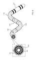
- Fig. 4 is a schematic exploded view illustrating an example of modules 100 that have been sequentially threaded onto tube 200, according to an embodiment of the present invention. For clarity, only sections of tube 200 are drawn in the figure; however, it will be understood that tube 200 is one element.
- cylindrical module 100A, 90° elbow module 100B, cylindrical module 100E, 90° elbow module 100C, and 60° elbow module 100D have been threaded onto tube 200. It will be understood that the modules butt against each other at their plane faces. For example, face 106C of module 100C butts against face 108E of module 100E.
- step 504 the assembled structure from step 502 is introduced into flexible insertion tube 300.
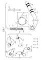
- Fig. 5 is a schematic exploded view of distal end 24 illustrating the insertion of modules 100, together with tube 200, into tube 300, so that the modules are contained within the insertion tube
- Fig. 6 is a schematic assembled view of the distal end after step 504 has been performed, according to embodiments of the present invention. While the grooves of tube 200 may match the grooves of the module the two sets of grooves are different in size, as is illustrated in the call-out showing face 106D and tube 200. The difference in size means that the assembly at this stage is unlocked.
- an expansion element herein assumed to comprise expansion wire 400, is inserted into expander tube 200 causing the tube to expand.
- Wire 400 acts as an expansion element for tube 200 by having a wire diameter larger than an unexpanded internal diameter of the tube.
- modules 100 that are in proximity to the end of wire 400 may be rotated to achieve a desired mutual alignment between adjacent modules, so as to achieve the shape desired by the professional (step 502). The rotation is possible since the modules terminate in plane faces, so that adjacent modules that butt against each other are able to rotate with respect to each other.
- the end of wire 400 may be partially withdrawn from tube 200, so allowing modules in proximity to the end to move out of alignment, enabling realignment of the modules by reintroduction of the wire into tube 200.
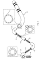
- Fig. 7 is a schematic exploded view of the beginning of insertion of expansion wire 400 into expander tube 200
- Fig. 8 is a schematic assembled view of distal end 24, after the expansion wire has been completely inserted into tube 200, according to embodiments of the present invention.
- flowchart 500 is but one example of the assembly of distal end 24, and that other methods for assembly, which will be apparent to those having ordinary skill in the art, may be used.
- tubing 300 may be slid over modules 100 after they have been locked in position by expansion of tube 200. All such methods are assumed to be comprised within the scope of the present invention.
- wire 400 is inserted into tube 200 so as to effect expansion of the tube by virtue of the different diameters of the wire and the internal diameter of the tube.
- wire 400 is initially cooled so as to have a diameter less than that of tube 200, so that upon heating up the wire expands to act as the required expansion element.
- the expansion element may comprise liquid, such as saline solution, or gas; either of these may be injected into tube 200 to expand the tube.
- liquid such as saline solution, or gas
- an expansion element that is solid, liquid, or gas is assumed to be comprised within the scope of the present invention.
- proximal end 28 sections intermediate the distal and proximal ends, and a section, such as a distal tip of distal end 24.
- proximal end 28 sections intermediate the distal and proximal ends
- a section such as a distal tip of distal end 24.
- the proximal and intermediate sections of probe 10 may be formed of a single tubular element which is inserted into tube 300 so as to contact a proximal module 100 of the distal end.
- the single tubular element is typically generally similar in cross-section dimensions to right cylindrical module 100A, so that it can accommodate passage of tube 200 to distal end 24.
- a single tubular element may only be grooved at its distal end.
- a distal tip of distal end 24 may be formed of a single tubular element, which may only be grooved at its proximal end.
Landscapes
- Health & Medical Sciences (AREA)
- Life Sciences & Earth Sciences (AREA)
- Engineering & Computer Science (AREA)
- Veterinary Medicine (AREA)
- Biomedical Technology (AREA)
- Heart & Thoracic Surgery (AREA)
- Animal Behavior & Ethology (AREA)
- General Health & Medical Sciences (AREA)
- Public Health (AREA)
- Biophysics (AREA)
- Pulmonology (AREA)
- Anesthesiology (AREA)
- Hematology (AREA)
- Surgery (AREA)
- Physics & Mathematics (AREA)
- Pathology (AREA)
- Medical Informatics (AREA)
- Molecular Biology (AREA)
- Cardiology (AREA)
- Human Computer Interaction (AREA)
- Physiology (AREA)
- Media Introduction/Drainage Providing Device (AREA)
- Measurement And Recording Of Electrical Phenomena And Electrical Characteristics Of The Living Body (AREA)
- Ultra Sonic Daignosis Equipment (AREA)
Applications Claiming Priority (1)
| Application Number | Priority Date | Filing Date | Title |
|---|---|---|---|
| US13/956,621 US9526867B2 (en) | 2013-08-01 | 2013-08-01 | Multishape catheter |
Publications (3)
| Publication Number | Publication Date |
|---|---|
| EP2832394A2 true EP2832394A2 (de) | 2015-02-04 |
| EP2832394A3 EP2832394A3 (de) | 2015-03-18 |
| EP2832394B1 EP2832394B1 (de) | 2016-06-08 |
Family
ID=51257359
Family Applications (1)
| Application Number | Title | Priority Date | Filing Date |
|---|---|---|---|
| EP14179230.9A Not-in-force EP2832394B1 (de) | 2013-08-01 | 2014-07-31 | Multishape-Katheter |
Country Status (7)
| Country | Link |
|---|---|
| US (2) | US9526867B2 (de) |
| EP (1) | EP2832394B1 (de) |
| JP (1) | JP6362951B2 (de) |
| CN (1) | CN104337512B (de) |
| AU (1) | AU2014208207B2 (de) |
| CA (1) | CA2857784A1 (de) |
| IL (1) | IL233698B (de) |
Families Citing this family (3)
| Publication number | Priority date | Publication date | Assignee | Title |
|---|---|---|---|---|
| US10357631B2 (en) | 2015-05-29 | 2019-07-23 | Covidien Lp | Catheter with tapering outer diameter |
| CA2987819C (en) * | 2015-05-29 | 2021-05-04 | Covidien Lp | Catheter with tapering outer diameter |
| US11219740B2 (en) | 2015-05-29 | 2022-01-11 | Covidien Lp | Catheter including tapering coil member |
Citations (6)
| Publication number | Priority date | Publication date | Assignee | Title |
|---|---|---|---|---|
| US4935017A (en) | 1988-04-29 | 1990-06-19 | C. R. Bard, Inc. | Variable shaped catheter system and method for catheterization |
| US7419477B2 (en) | 2002-03-22 | 2008-09-02 | Cardiac Pacemakers, Inc. | Catheterization method using proximal articulation and pre-formed distal end |
| US20120109079A1 (en) | 2010-10-29 | 2012-05-03 | Medtronic, Inc. | Telescoping Catheter Delivery System for Left Heart Endocardial Device Placement |
| US8313478B2 (en) | 2001-06-07 | 2012-11-20 | Cardiac Pacemakers, Inc. | Method for manipulating an adjustable shape guide catheter |
| US8323171B2 (en) | 2002-09-10 | 2012-12-04 | Cianna Medical, Inc. | Brachytherapy apparatus and methods for using same |
| US8326423B2 (en) | 2004-12-20 | 2012-12-04 | Cardiac Pacemakers, Inc. | Devices and methods for steering electrical stimulation in cardiac rhythm management |
Family Cites Families (8)
| Publication number | Priority date | Publication date | Assignee | Title |
|---|---|---|---|---|
| US6730105B2 (en) * | 1988-07-29 | 2004-05-04 | Samuel Shiber | Clover leaf shaped tubular medical device |
| US5569221A (en) | 1994-07-07 | 1996-10-29 | Ep Technologies, Inc. | Catheter component bond and method |
| WO1998050098A1 (en) | 1997-05-08 | 1998-11-12 | Microvena Corporation | Improved multi-durometer catheter |
| US6671533B2 (en) * | 2001-10-11 | 2003-12-30 | Irvine Biomedical Inc. | System and method for mapping and ablating body tissue of the interior region of the heart |
| US9974887B2 (en) | 2005-10-04 | 2018-05-22 | Clph, Llc | Catheters with lubricious linings and methods for making and using them |
| US20080077165A1 (en) * | 2006-02-24 | 2008-03-27 | National University Of Ireland, Galway | Minimally Invasive Intravascular Treatment Device |
| US8114144B2 (en) | 2007-10-17 | 2012-02-14 | Abbott Cardiovascular Systems Inc. | Rapid-exchange retractable sheath self-expanding delivery system with incompressible inner member and flexible distal assembly |
| US9314591B2 (en) | 2010-05-11 | 2016-04-19 | Cathrx Ltd | Catheter shape adjustment mechanism |
-
2013
- 2013-08-01 US US13/956,621 patent/US9526867B2/en not_active Expired - Fee Related
-
2014
- 2014-07-17 IL IL233698A patent/IL233698B/en active IP Right Grant
- 2014-07-24 CA CA2857784A patent/CA2857784A1/en not_active Abandoned
- 2014-07-30 AU AU2014208207A patent/AU2014208207B2/en not_active Ceased
- 2014-07-31 EP EP14179230.9A patent/EP2832394B1/de not_active Not-in-force
- 2014-07-31 JP JP2014156037A patent/JP6362951B2/ja not_active Expired - Fee Related
- 2014-08-01 CN CN201410378159.7A patent/CN104337512B/zh not_active Expired - Fee Related
-
2016
- 2016-09-21 US US15/271,608 patent/US9993611B2/en active Active
Patent Citations (6)
| Publication number | Priority date | Publication date | Assignee | Title |
|---|---|---|---|---|
| US4935017A (en) | 1988-04-29 | 1990-06-19 | C. R. Bard, Inc. | Variable shaped catheter system and method for catheterization |
| US8313478B2 (en) | 2001-06-07 | 2012-11-20 | Cardiac Pacemakers, Inc. | Method for manipulating an adjustable shape guide catheter |
| US7419477B2 (en) | 2002-03-22 | 2008-09-02 | Cardiac Pacemakers, Inc. | Catheterization method using proximal articulation and pre-formed distal end |
| US8323171B2 (en) | 2002-09-10 | 2012-12-04 | Cianna Medical, Inc. | Brachytherapy apparatus and methods for using same |
| US8326423B2 (en) | 2004-12-20 | 2012-12-04 | Cardiac Pacemakers, Inc. | Devices and methods for steering electrical stimulation in cardiac rhythm management |
| US20120109079A1 (en) | 2010-10-29 | 2012-05-03 | Medtronic, Inc. | Telescoping Catheter Delivery System for Left Heart Endocardial Device Placement |
Also Published As
| Publication number | Publication date |
|---|---|
| AU2014208207A1 (en) | 2015-02-19 |
| EP2832394A3 (de) | 2015-03-18 |
| US20170043121A1 (en) | 2017-02-16 |
| US9993611B2 (en) | 2018-06-12 |
| JP6362951B2 (ja) | 2018-07-25 |
| CN104337512B (zh) | 2019-04-23 |
| US20150038900A1 (en) | 2015-02-05 |
| AU2014208207B2 (en) | 2019-04-04 |
| IL233698B (en) | 2018-01-31 |
| EP2832394B1 (de) | 2016-06-08 |
| CN104337512A (zh) | 2015-02-11 |
| US9526867B2 (en) | 2016-12-27 |
| JP2015029912A (ja) | 2015-02-16 |
| CA2857784A1 (en) | 2015-02-01 |
Similar Documents
| Publication | Publication Date | Title |
|---|---|---|
| US20230173224A1 (en) | Drug Delivery Systems and Methods | |
| US11457974B2 (en) | Catheter having flexible tip with multiple flexible segments | |
| US20170281268A1 (en) | Basket catheter structural elements | |
| RU2542088C2 (ru) | Катетер с регулируемой дугообразной дистальной секцией | |
| EP3052176B1 (de) | Radial- und transendokardialer freisetzungskatheter | |
| EP3222209A1 (de) | Dispergierte bewässerungskonfiguration für katheterspitzenentwurf | |
| US20150342532A1 (en) | High electrode density basket catheter | |
| CN106999211B (zh) | 卵圆窝穿透 | |
| CN105879197A (zh) | 血管成形术导丝 | |
| CN105919589B (zh) | 带传感器的头端具有盘状螺旋结构的磁定位环状标测电极导管 | |
| US9993611B2 (en) | Multishape catheter | |
| US20140228831A1 (en) | Ablation applicator with a matrix filled with particles | |
| US20170071661A1 (en) | Dual node multiray electrode catheter | |
| US20250195126A1 (en) | Near-critical argon based loop catheter for circumferential ablation of nerve fibers | |
| AU2016200681B2 (en) | Navigation of an angioplasty guidewire | |
| US11883092B2 (en) | Radiofrequency ablation catheter apparatus with meshed carrier having stabilized shape, system thereof and methods thereof | |
| US20170071660A1 (en) | Dual node multiray electrode catheter | |
| CN118141503A (zh) | 导管、磁场发生器、磁导航系统及医疗系统 |
Legal Events
| Date | Code | Title | Description |
|---|---|---|---|
| 17P | Request for examination filed |
Effective date: 20140731 |
|
| AK | Designated contracting states |
Kind code of ref document: A2 Designated state(s): AL AT BE BG CH CY CZ DE DK EE ES FI FR GB GR HR HU IE IS IT LI LT LU LV MC MK MT NL NO PL PT RO RS SE SI SK SM TR |
|
| AX | Request for extension of the european patent |
Extension state: BA ME |
|
| PUAI | Public reference made under article 153(3) epc to a published international application that has entered the european phase |
Free format text: ORIGINAL CODE: 0009012 |
|
| PUAL | Search report despatched |
Free format text: ORIGINAL CODE: 0009013 |
|
| AK | Designated contracting states |
Kind code of ref document: A3 Designated state(s): AL AT BE BG CH CY CZ DE DK EE ES FI FR GB GR HR HU IE IS IT LI LT LU LV MC MK MT NL NO PL PT RO RS SE SI SK SM TR |
|
| AX | Request for extension of the european patent |
Extension state: BA ME |
|
| RIC1 | Information provided on ipc code assigned before grant |
Ipc: A61M 25/00 20060101AFI20150209BHEP |
|
| R17P | Request for examination filed (corrected) |
Effective date: 20150827 |
|
| RBV | Designated contracting states (corrected) |
Designated state(s): AL AT BE BG CH CY CZ DE DK EE ES FI FR GB GR HR HU IE IS IT LI LT LU LV MC MK MT NL NO PL PT RO RS SE SI SK SM TR |
|
| GRAP | Despatch of communication of intention to grant a patent |
Free format text: ORIGINAL CODE: EPIDOSNIGR1 |
|
| INTG | Intention to grant announced |
Effective date: 20160315 |
|
| RAP1 | Party data changed (applicant data changed or rights of an application transferred) |
Owner name: BIOSENSE WEBSTER (ISRAEL) LTD. |
|
| GRAS | Grant fee paid |
Free format text: ORIGINAL CODE: EPIDOSNIGR3 |
|
| GRAA | (expected) grant |
Free format text: ORIGINAL CODE: 0009210 |
|
| AK | Designated contracting states |
Kind code of ref document: B1 Designated state(s): AL AT BE BG CH CY CZ DE DK EE ES FI FR GB GR HR HU IE IS IT LI LT LU LV MC MK MT NL NO PL PT RO RS SE SI SK SM TR |
|
| REG | Reference to a national code |
Ref country code: GB Ref legal event code: FG4D |
|
| REG | Reference to a national code |
Ref country code: FR Ref legal event code: PLFP Year of fee payment: 3 |
|
| REG | Reference to a national code |
Ref country code: CH Ref legal event code: EP |
|
| REG | Reference to a national code |
Ref country code: IE Ref legal event code: FG4D |
|
| REG | Reference to a national code |
Ref country code: AT Ref legal event code: REF Ref document number: 804768 Country of ref document: AT Kind code of ref document: T Effective date: 20160715 |
|
| REG | Reference to a national code |
Ref country code: DE Ref legal event code: R096 Ref document number: 602014002237 Country of ref document: DE |
|
| REG | Reference to a national code |
Ref country code: NL Ref legal event code: FP |
|
| REG | Reference to a national code |
Ref country code: LT Ref legal event code: MG4D |
|
| PG25 | Lapsed in a contracting state [announced via postgrant information from national office to epo] |
Ref country code: NO Free format text: LAPSE BECAUSE OF FAILURE TO SUBMIT A TRANSLATION OF THE DESCRIPTION OR TO PAY THE FEE WITHIN THE PRESCRIBED TIME-LIMIT Effective date: 20160908 Ref country code: FI Free format text: LAPSE BECAUSE OF FAILURE TO SUBMIT A TRANSLATION OF THE DESCRIPTION OR TO PAY THE FEE WITHIN THE PRESCRIBED TIME-LIMIT Effective date: 20160608 Ref country code: LT Free format text: LAPSE BECAUSE OF FAILURE TO SUBMIT A TRANSLATION OF THE DESCRIPTION OR TO PAY THE FEE WITHIN THE PRESCRIBED TIME-LIMIT Effective date: 20160608 |
|
| REG | Reference to a national code |
Ref country code: AT Ref legal event code: MK05 Ref document number: 804768 Country of ref document: AT Kind code of ref document: T Effective date: 20160608 |
|
| PG25 | Lapsed in a contracting state [announced via postgrant information from national office to epo] |
Ref country code: RS Free format text: LAPSE BECAUSE OF FAILURE TO SUBMIT A TRANSLATION OF THE DESCRIPTION OR TO PAY THE FEE WITHIN THE PRESCRIBED TIME-LIMIT Effective date: 20160608 Ref country code: LV Free format text: LAPSE BECAUSE OF FAILURE TO SUBMIT A TRANSLATION OF THE DESCRIPTION OR TO PAY THE FEE WITHIN THE PRESCRIBED TIME-LIMIT Effective date: 20160608 Ref country code: GR Free format text: LAPSE BECAUSE OF FAILURE TO SUBMIT A TRANSLATION OF THE DESCRIPTION OR TO PAY THE FEE WITHIN THE PRESCRIBED TIME-LIMIT Effective date: 20160909 Ref country code: ES Free format text: LAPSE BECAUSE OF FAILURE TO SUBMIT A TRANSLATION OF THE DESCRIPTION OR TO PAY THE FEE WITHIN THE PRESCRIBED TIME-LIMIT Effective date: 20160608 Ref country code: SE Free format text: LAPSE BECAUSE OF FAILURE TO SUBMIT A TRANSLATION OF THE DESCRIPTION OR TO PAY THE FEE WITHIN THE PRESCRIBED TIME-LIMIT Effective date: 20160608 Ref country code: HR Free format text: LAPSE BECAUSE OF FAILURE TO SUBMIT A TRANSLATION OF THE DESCRIPTION OR TO PAY THE FEE WITHIN THE PRESCRIBED TIME-LIMIT Effective date: 20160608 |
|
| PG25 | Lapsed in a contracting state [announced via postgrant information from national office to epo] |
Ref country code: RO Free format text: LAPSE BECAUSE OF FAILURE TO SUBMIT A TRANSLATION OF THE DESCRIPTION OR TO PAY THE FEE WITHIN THE PRESCRIBED TIME-LIMIT Effective date: 20160608 Ref country code: EE Free format text: LAPSE BECAUSE OF FAILURE TO SUBMIT A TRANSLATION OF THE DESCRIPTION OR TO PAY THE FEE WITHIN THE PRESCRIBED TIME-LIMIT Effective date: 20160608 Ref country code: SK Free format text: LAPSE BECAUSE OF FAILURE TO SUBMIT A TRANSLATION OF THE DESCRIPTION OR TO PAY THE FEE WITHIN THE PRESCRIBED TIME-LIMIT Effective date: 20160608 Ref country code: CZ Free format text: LAPSE BECAUSE OF FAILURE TO SUBMIT A TRANSLATION OF THE DESCRIPTION OR TO PAY THE FEE WITHIN THE PRESCRIBED TIME-LIMIT Effective date: 20160608 Ref country code: IS Free format text: LAPSE BECAUSE OF FAILURE TO SUBMIT A TRANSLATION OF THE DESCRIPTION OR TO PAY THE FEE WITHIN THE PRESCRIBED TIME-LIMIT Effective date: 20161008 |
|
| PG25 | Lapsed in a contracting state [announced via postgrant information from national office to epo] |
Ref country code: PT Free format text: LAPSE BECAUSE OF FAILURE TO SUBMIT A TRANSLATION OF THE DESCRIPTION OR TO PAY THE FEE WITHIN THE PRESCRIBED TIME-LIMIT Effective date: 20161010 Ref country code: PL Free format text: LAPSE BECAUSE OF FAILURE TO SUBMIT A TRANSLATION OF THE DESCRIPTION OR TO PAY THE FEE WITHIN THE PRESCRIBED TIME-LIMIT Effective date: 20160608 Ref country code: SM Free format text: LAPSE BECAUSE OF FAILURE TO SUBMIT A TRANSLATION OF THE DESCRIPTION OR TO PAY THE FEE WITHIN THE PRESCRIBED TIME-LIMIT Effective date: 20160608 Ref country code: AT Free format text: LAPSE BECAUSE OF FAILURE TO SUBMIT A TRANSLATION OF THE DESCRIPTION OR TO PAY THE FEE WITHIN THE PRESCRIBED TIME-LIMIT Effective date: 20160608 |
|
| REG | Reference to a national code |
Ref country code: DE Ref legal event code: R097 Ref document number: 602014002237 Country of ref document: DE |
|
| PG25 | Lapsed in a contracting state [announced via postgrant information from national office to epo] |
Ref country code: MC Free format text: LAPSE BECAUSE OF FAILURE TO SUBMIT A TRANSLATION OF THE DESCRIPTION OR TO PAY THE FEE WITHIN THE PRESCRIBED TIME-LIMIT Effective date: 20160608 |
|
| PLBE | No opposition filed within time limit |
Free format text: ORIGINAL CODE: 0009261 |
|
| STAA | Information on the status of an ep patent application or granted ep patent |
Free format text: STATUS: NO OPPOSITION FILED WITHIN TIME LIMIT |
|
| REG | Reference to a national code |
Ref country code: IE Ref legal event code: MM4A |
|
| 26N | No opposition filed |
Effective date: 20170309 |
|
| PG25 | Lapsed in a contracting state [announced via postgrant information from national office to epo] |
Ref country code: DK Free format text: LAPSE BECAUSE OF FAILURE TO SUBMIT A TRANSLATION OF THE DESCRIPTION OR TO PAY THE FEE WITHIN THE PRESCRIBED TIME-LIMIT Effective date: 20160608 Ref country code: SI Free format text: LAPSE BECAUSE OF FAILURE TO SUBMIT A TRANSLATION OF THE DESCRIPTION OR TO PAY THE FEE WITHIN THE PRESCRIBED TIME-LIMIT Effective date: 20160608 |
|
| REG | Reference to a national code |
Ref country code: FR Ref legal event code: PLFP Year of fee payment: 4 |
|
| PG25 | Lapsed in a contracting state [announced via postgrant information from national office to epo] |
Ref country code: IE Free format text: LAPSE BECAUSE OF NON-PAYMENT OF DUE FEES Effective date: 20160731 |
|
| PG25 | Lapsed in a contracting state [announced via postgrant information from national office to epo] |
Ref country code: LU Free format text: LAPSE BECAUSE OF NON-PAYMENT OF DUE FEES Effective date: 20160731 |
|
| REG | Reference to a national code |
Ref country code: CH Ref legal event code: PL |
|
| PG25 | Lapsed in a contracting state [announced via postgrant information from national office to epo] |
Ref country code: CH Free format text: LAPSE BECAUSE OF NON-PAYMENT OF DUE FEES Effective date: 20170731 Ref country code: LI Free format text: LAPSE BECAUSE OF NON-PAYMENT OF DUE FEES Effective date: 20170731 |
|
| PG25 | Lapsed in a contracting state [announced via postgrant information from national office to epo] |
Ref country code: HU Free format text: LAPSE BECAUSE OF FAILURE TO SUBMIT A TRANSLATION OF THE DESCRIPTION OR TO PAY THE FEE WITHIN THE PRESCRIBED TIME-LIMIT; INVALID AB INITIO Effective date: 20140731 |
|
| REG | Reference to a national code |
Ref country code: FR Ref legal event code: PLFP Year of fee payment: 5 |
|
| PG25 | Lapsed in a contracting state [announced via postgrant information from national office to epo] |
Ref country code: CY Free format text: LAPSE BECAUSE OF FAILURE TO SUBMIT A TRANSLATION OF THE DESCRIPTION OR TO PAY THE FEE WITHIN THE PRESCRIBED TIME-LIMIT Effective date: 20160608 Ref country code: MK Free format text: LAPSE BECAUSE OF FAILURE TO SUBMIT A TRANSLATION OF THE DESCRIPTION OR TO PAY THE FEE WITHIN THE PRESCRIBED TIME-LIMIT Effective date: 20160608 Ref country code: MT Free format text: LAPSE BECAUSE OF NON-PAYMENT OF DUE FEES Effective date: 20160731 |
|
| PG25 | Lapsed in a contracting state [announced via postgrant information from national office to epo] |
Ref country code: BG Free format text: LAPSE BECAUSE OF FAILURE TO SUBMIT A TRANSLATION OF THE DESCRIPTION OR TO PAY THE FEE WITHIN THE PRESCRIBED TIME-LIMIT Effective date: 20160608 |
|
| PG25 | Lapsed in a contracting state [announced via postgrant information from national office to epo] |
Ref country code: TR Free format text: LAPSE BECAUSE OF FAILURE TO SUBMIT A TRANSLATION OF THE DESCRIPTION OR TO PAY THE FEE WITHIN THE PRESCRIBED TIME-LIMIT Effective date: 20160608 Ref country code: AL Free format text: LAPSE BECAUSE OF FAILURE TO SUBMIT A TRANSLATION OF THE DESCRIPTION OR TO PAY THE FEE WITHIN THE PRESCRIBED TIME-LIMIT Effective date: 20160608 |
|
| PGFP | Annual fee paid to national office [announced via postgrant information from national office to epo] |
Ref country code: BE Payment date: 20200617 Year of fee payment: 7 |
|
| REG | Reference to a national code |
Ref country code: BE Ref legal event code: MM Effective date: 20210731 |
|
| PG25 | Lapsed in a contracting state [announced via postgrant information from national office to epo] |
Ref country code: BE Free format text: LAPSE BECAUSE OF NON-PAYMENT OF DUE FEES Effective date: 20210731 |
|
| PGFP | Annual fee paid to national office [announced via postgrant information from national office to epo] |
Ref country code: NL Payment date: 20220615 Year of fee payment: 9 Ref country code: IT Payment date: 20220613 Year of fee payment: 9 Ref country code: GB Payment date: 20220609 Year of fee payment: 9 |
|
| PGFP | Annual fee paid to national office [announced via postgrant information from national office to epo] |
Ref country code: FR Payment date: 20220609 Year of fee payment: 9 |
|
| PGFP | Annual fee paid to national office [announced via postgrant information from national office to epo] |
Ref country code: DE Payment date: 20220608 Year of fee payment: 9 |
|
| REG | Reference to a national code |
Ref country code: DE Ref legal event code: R119 Ref document number: 602014002237 Country of ref document: DE |
|
| REG | Reference to a national code |
Ref country code: NL Ref legal event code: MM Effective date: 20230801 |
|
| GBPC | Gb: european patent ceased through non-payment of renewal fee |
Effective date: 20230731 |
|
| PG25 | Lapsed in a contracting state [announced via postgrant information from national office to epo] |
Ref country code: NL Free format text: LAPSE BECAUSE OF NON-PAYMENT OF DUE FEES Effective date: 20230801 |
|
| PG25 | Lapsed in a contracting state [announced via postgrant information from national office to epo] |
Ref country code: NL Free format text: LAPSE BECAUSE OF NON-PAYMENT OF DUE FEES Effective date: 20230801 Ref country code: DE Free format text: LAPSE BECAUSE OF NON-PAYMENT OF DUE FEES Effective date: 20240201 Ref country code: GB Free format text: LAPSE BECAUSE OF NON-PAYMENT OF DUE FEES Effective date: 20230731 |
|
| PG25 | Lapsed in a contracting state [announced via postgrant information from national office to epo] |
Ref country code: FR Free format text: LAPSE BECAUSE OF NON-PAYMENT OF DUE FEES Effective date: 20230731 |
|
| PG25 | Lapsed in a contracting state [announced via postgrant information from national office to epo] |
Ref country code: IT Free format text: LAPSE BECAUSE OF NON-PAYMENT OF DUE FEES Effective date: 20230731 |